1. Introduction
Research on regenerative suspension systems has gained increasing interest in recent years for the potential energy savings achievable in implementing active control strategies that ensure enhanced dynamic performance and the ability to convert wasted kinetic energy in electrical power for both energy harvesting and self-powered implementation. The state-of-the-art in the field has been recently reviewed in [
1,
2].
In a typical regenerative setup the viscous shock absorber is usually replaced by an electrical actuator that can be regulated to mimic a standard shock absorber (virtual shock absorber) or to provide a more general dynamical behavior in order to better trade-off between the conflicting requirements of harvesting large amounts of energy and ensuring good road handling and ride comfort performance.
In [
3] a multiobjective
control design methodology has been recently proposed for actively regulating regenerative suspension systems and it was shown to be much more flexible in trading-off among conflicting requirements and capable to dramatically improve the amount of harvested energy with respect to PI controllers implementing virtual shock absorbers where the only design knob is the dumping parameter.
The specificity of the control strategy proposed in [
3], there referred to as Maximum Induced Power Control (MIPC) strategy, is that it may directly consider the amount of energy to be harvested amongst its objectives. This is done by imposing a model-reference prescription in closed-loop to the kinetic energy coming from the road that makes it arbitrarily large and sign-defined. The rationale is that, in the average, the amount of harvested electrical energy cannot be greater than the energy drained into the system from the road unevenness. Thus, maximizing the energy induced by the road and making it sign-defined may be a more effective control design objective in order to increase the amount of harvestable energy. Simulations and comparisons undertaken in [
3] have confirmed the flexibility and the potentiality of the MIPC approach. A gain-scheduling version based on a LPV system formulation can be found in [
4]. Similar conclusions on the superiority of the MIPC approach in terms of energy requirements for implementing the control strategy in comparison with standard passive control strategies were also drawn out in [
5], where experimental comparisons of several control laws were undertaken on a lab regenerative shock absorber prototype.
One of the limitations of the MIPC approach described in [
3] is that it is based on a quarter-car model and is limited to regulate the behavior of the regenerative suspension system of a single wheel. This approach obviously produces sub-optimal results because the four MIPC control laws are individually applied to the four wheels of the vehicles in a decentralized way, and the pitch and roll motions have not directly been taken into account in the design phase. As a consequence, each regulated suspension has the same dynamic behavior and provides the same amount of energy. Then, the total amount is simply given by four times the energy harvested by a single wheel. This approach, although suboptimal, is anyway of interest here because it will be used as a baseline solution for comparison purposes.
The main contribution of this paper is to present complete multivariable centralized MIPC approach is presented for the four wheels of a vehicle based on a full-car model of the regenerative suspension system. Both multi-objective and state-feedback control strategies are presented based on standard LMI control design formulations. Dynamical output feedback control syntheses are also possible but the details are not presented here for space limitation.
A final example is provided where comparisons among the decentralized state-feedback
solution of [
3], and the centralized state-feedback
and
solutions presented here are reported. From these simulations, as expected, it clearly results that the multivariable centralized
and
MIPC approaches proposed here overcome the decentralized implementation because of the better system description, the coordinated implementation of the four controllers and the extra degrees of freedom available for the optimization. Moreover, it is also found that the centralized
approach allows one to harvest larger amount of energy for the same ride comfort requirement than the
MIPC approaches.
2. The Model and the Overall Control Architecture
2.1. The Full-Car Regenerative Suspension Model
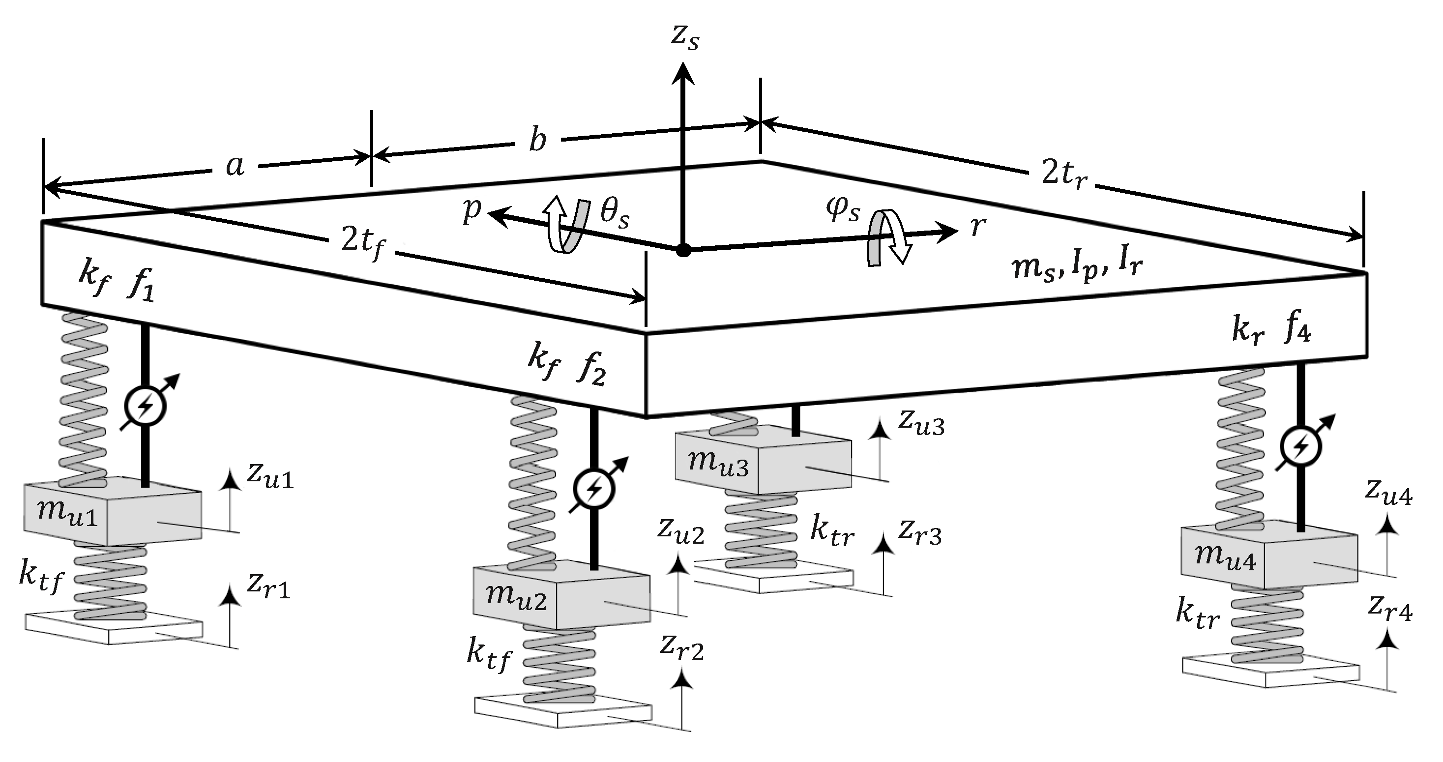
The full-car regenerative suspension schematic under consideration is depicted in
Figure 1. In such a system, the passive viscous dampers, usually present in any passive suspension systems for all four wheels, are here replaced by electromechanical actuators that generate forces
so as to suitably dampen the vertical, pitch and roll motions of the car body.
The 7DOF mathematical model proposed in [
6] is used here to describe the pitch
and roll
rotational motions (with
and
the corresponding moments of inertia) and the vertical motion of the sprung mass
along its center of mass
. They consist of the following coupled linear differential equations (the dependance on the time is omitted for simplicity)
where
denote the vertical motions of the four unsprung masses described by
In the above equations
and
represent the front wheels whereas
and
the rear ones, whose coupling with the road is simply modeled by the elastic stiffnesses
and
(for the front and rear couples of tires respectively). Moreover,
and
are the front and rear suspension stiffnesses respectively. Notice in particular that
represent the vertical motions of the car body corners that, under a usual small pitch and roll angles assumption, are related to
,
and
via the following linear expressions
Finally, the parameters a, b, and characterize geometrically the car body, denote the road profiles, the suspension strokes and the tire deflections.
2.2. Power Flow Analysis
In order to arrive to consistent guidelines on how to maximize the harvested electrical power, a power flows analysis of the regenerative suspension system is accomplished in this subsection. To this end, with reference to
Figure 1, one notes that the only exogenous signals that provide power to the regenerative suspension system are the four road profiles
and no dissipative units, like viscous shock absorbers are present.
Then, by writing down the total energy
of the system, as the sum of the kinetic energy
K of the masses and the potential energy
V of the springs, one has
Because power cannot be dissipated within the suspension system of
Figure 1, it can only be exchanged with the road via its irregularities
and with the electromagnetic devices via the exchanged forces
. In particular, such an exchanged power can be positive or negative. In fact, the road can introduce kinetic energy via the irregularities and absorbs part of the potential energy of the suspension during their discharging. On the other hand, the electromagnetic devices can act either as motors or generators by introducing or absorbing energy from the system.
Then, it makes sense to consider the power exchanged with the road
and the mechanical power exchanged with the actuators
and express the total instantaneous power
in terms of the above two terms
By exploiting (
1)–(7) and after direct mathematical manipulations one arrives to
and, on the basis of the above considerations, one can recognize that the power contribution from the road profiles and the actuators are clearly indetifiable
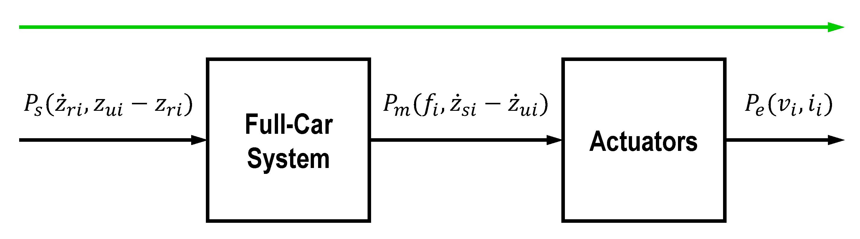
As a result, as far as the exchanged power flows are concerned, the system can be considered as a series of two-port subsystems, as depicted in
Figure 2, where the power
exchanged with the road acts at one terminal of the first subsystem, the mechanical power
is then exchanged with the electromechanical actuators that provide/request the electrical power
. In all terminals of the two-port systems we adopt the convention that the power is entering into the system when positive.
The above expressions for
and
generalized the ones achieved in [
3] for a single regenerative suspension system derived from a quarter-car model and the same considerations can be drawn out here, briefly recalled hereafter for the reader convenience:
Ideally one would like to dispose of a control action capable to make both quantities large and sign defined for all time:
If this were possible it would imply , which would ensure that the system has a perfect transfer of energy from the road to the electrical batteries.
Because
are directly manipulable variables, it is quite easy to make
sign-defined. However,
expresses an obvious constraint on the energy that can be harvested in any interval
of interest, which cannot be larger than the energy provided by the road. Thus, it might make nonsense to try to maximize
by suitably design the control actions if
were small without disposing of any control degree of freedom to increase its amount any further.
Observe first that is zero when the road profiles are all completely flat () or when the tire deflections are all zero, . Thus, high levels of energy harvesting on flat roads are incompatible with good road handling performance. From a control perspective, observe also that depends on the regulated variables . Thus, if were made sign-defined and as large as possible, viz. via a suitable control law this would increase the harvested energy regardless of the behavior (the sign) of . Roughly speaking, making it would provide a barrier for the internal energy of the system from flowing back towards the road.
The above considerations were at the basis of the Maximum Induced Power Control (MIPC) decentralized design approach of [
3] that will be extended here to the multivariable centralized case. It is expected that the more degrees of freedom arising in driving all four electromagnetic actuators by a single multivariable centralized controllers make easier the achievement of the above control requirements with respect to the use of four decentralized and no coordinated control actions.
2.3. Electromechanical Actuator Model
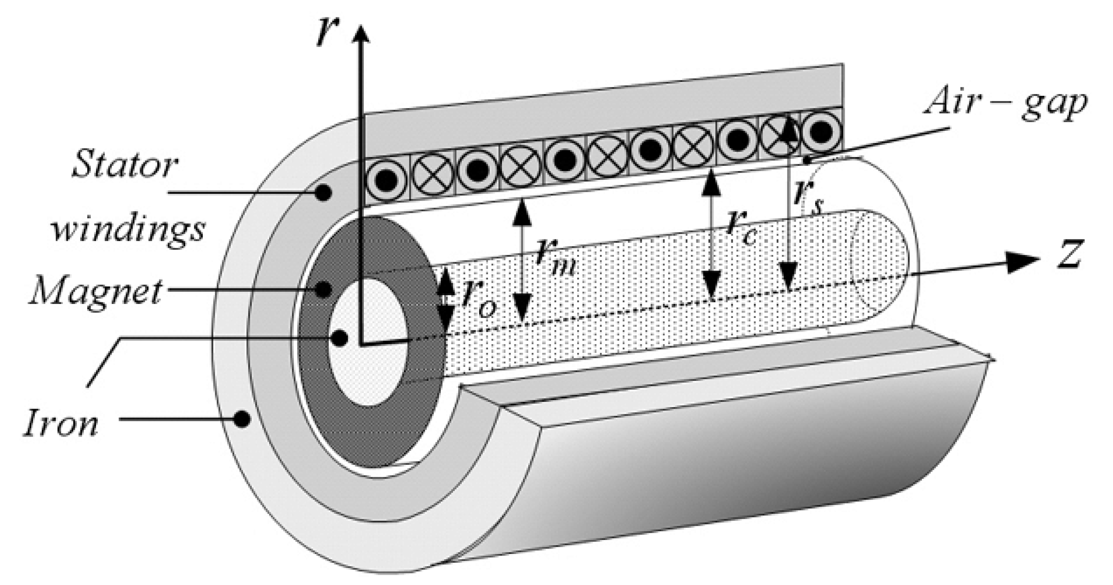
In this paper we consider four identical linear permanent-magnets electromechanical devices depicted in
Figure 3 as a force actuators (LPMA) for the four wheels. Simple linear models of the generic LPMA actuator are given by
for
where
are the damping forces,
the armature currents,
the armature voltages and
the speed of the suspension stroke. The parameters
and
represent respectively the armature resistances and inductances while
are the force constants. The terms
represent the back EMF voltages whereas the forces are proportional to the corresponding armature currents. The electrical power
results to be given by
where:
represents the power dissipated by the Joule effect,
the electrical power stored in the inductance
and
the mechanical power acting on the
i-th actuators. For a more accurate analysis of the dynamics of electromechanical devices well suited for energy harvesting purposes and their models see e.g., [
7], where a discussion of the validity of assuming constant the coupling coefficients between the electrical and mechanical parts of the device is reported.
Thus, Equation (
23) suggests to work with electrical machines characterized by high voltages and low currents, in order to have small Joule losses and, in turn, a good efficiency. This requires actuators with large values of force constants
and small values for
. Other losses are relevant only for high currents and are here neglected for simplicity.
2.4. The Overall Control Architecture
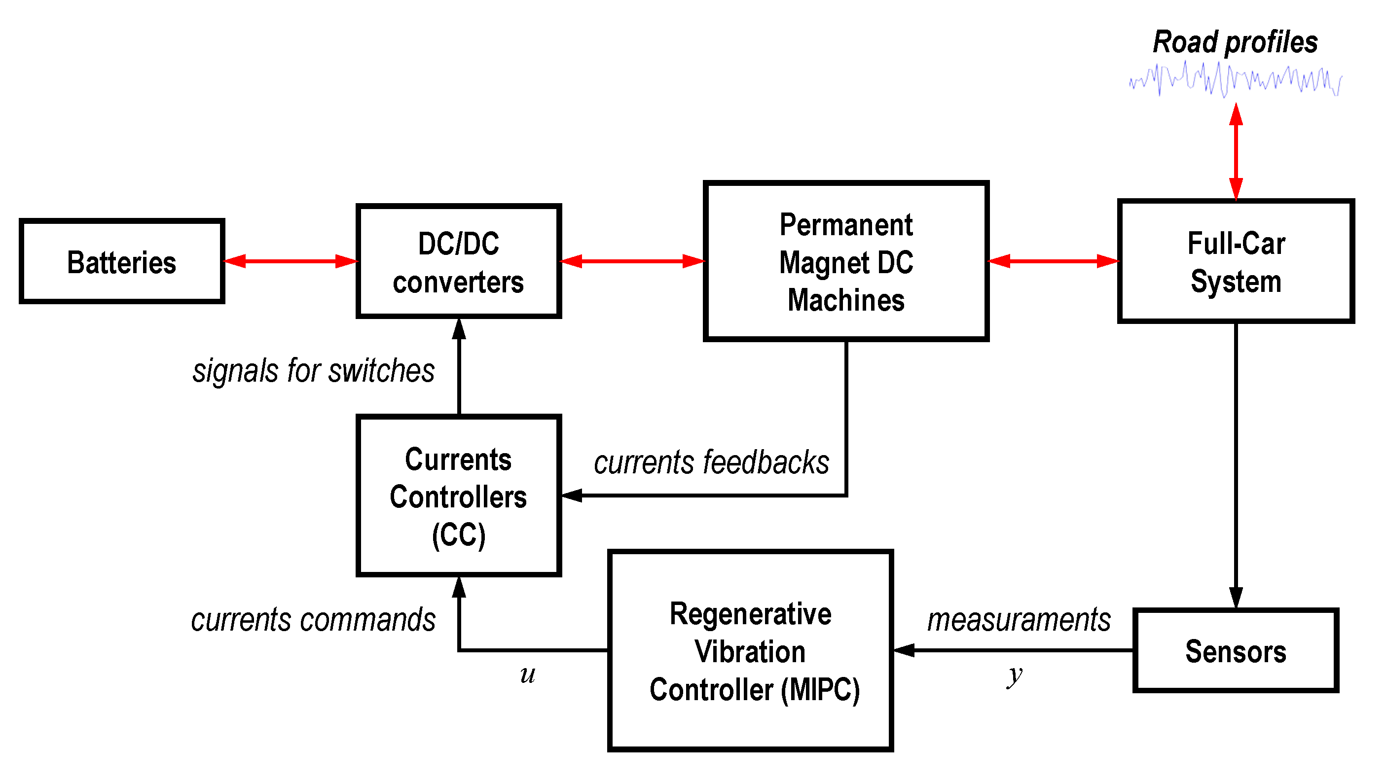
Figure 4 depicts the overall control architecture where two nested control loops are present. The inner one is governed by the
Current Controller (CC) while the outer controller is termed
Regenerative Vibration Controller (RVC) and it is in charge to provide the currents set-points to the inner CC controller.
The CC controller aims at regulating the armature current loops in the bank of four bidirectional DC-DC converters which establish the bidirectional electrical power flows between the battery and the four actuators. Its design is not considered here while we focus on the design of the RVC controller which is expected to provide the usual control performance of standard active suspension systems plus the ability to harvest as much energy as possibile. Among many, for brevity, only optimal and centralized and decentralized static state-feedback control actions will be considered for the design of the RVC controller. Dynamic output feedback approaches will be considered in a future work.
3. RVC Control Design Specifications and LMI Based Designs
3.1. Ride Comfort and Road Handling Control Specifications
Traditional control specifications in classical passive and active suspension systems mainly consists of finding a suitable trade-off between the
ride comfort and
road handling requirements, see e.g., [
8,
9].
Ride comfort is related to the passengers perception of vibrations at various frequency (0.5–80 Hz) that greatly depends on the capability of the suspension systems to attenuate the perceived acceleration levels as much as possibile, especially at those frequencies more dangerous for the human body (0.5–5 Hz). Studies have shown that ride comfort may be directly related to sprung mass vertical accelerations and/or .
In order to avoid subjectivity, the ISO-2631 standard (see [
10]) defines an index, referred to as the
Ride Index (RI), that quantifies the human exposure to vibration by weighting the perceived acceleration by a human sensitivity curve defined by a band-pass filter:
where
is the acceleration along the
i-th axis weighed by the following filter:
Lower values of the ride index imply better vibrations attenuation.
Road handling is another important objective, related to vehicle and passengers’ safety. It becomes extremely important in sportive/racing cars. It can usually be represented by the tire deflection that has to be minimized in some norm.
3.2. Energy Harvesting Control Specification
A further requirement of a regenerative suspension system is that to harvest energy from the road unevenness. Based on the above considerations, this requirements is here optimized by making sign-defined and as larger as possible.
This condition could be achieved by trying to enforce the following conditions on the tire deflections in closed-loop
where
is a free constant design parameter. If all such conditions were satisfied for all time instants, the power
would result
In this way, in principle, would be always positive (the power would always flow from the road to the suspension system) and large as desired by choosing a suitable large . However, it is worth pointing out that making the tire deflections large is in contrast with good road handling performance. Moreover, high levels of harvested energy require high armature currents that increase the electrical losses in the actuators. Then, depending on the application at hands, a suitable trade-off among the above conflicting control specifications has to be addressed in the design the RVC controller that can naturally formulated as a multi-objective optimal control design problem.
In fact, conditions (
27) can be reformulated as the following model reference errors
to be minimized
3.3. State-Space Realization for the RVC Control Synthesis
Because the need of having a system description which uses the derivatives
instead of
as exogenous signals for causally realizing
in (
29) we extend to the full-car case the alternative state-space representations used in [
11,
12] for the quarter-car model. The following state-space representation results
corresponding to the following system vectors
for certain matrices
A,
B and
C detailed in [
13].
It is worth pointing out that the above state-space realization is not minimal in that the state has dimension 15 while the 7DOF full-car model (
1)–(7) could be realized by a state of dimension 14. This choice is dictated by the greater easiness in specifying the various control objectives for the design of the controller that this realization offers.
The extra dimension has as a consequence that
. In fact, it can be observed that
A has one dominant real eigenvalue in zero and seven couple of pure imaginary coniugate eigenvalues. The eigenvalue in zero expresses the fact a linear combinations of state components remains constant during the free evolutions of the systems. In particular, it is found that the following linear dependence arises
along all the free evolutions of the system (
). This condition trivially results by considering (
8)–(
11) and expresses the fact that in a rigid body the positions of three points are sufficient to characterize the positions of all other points of the body.
The state-space realization (
30) is fully controllable. Thus, if the state is fully measurable (
) linear state-feedback control laws can be freely designed. On the contrary, if only an output is available
it is also full observable for many choices of sensors. For example, in [
13] it is shown that the pair
corresponding to the following output
is full observable. In this second case, one has full freedom in designing any form of dynamic output feedback control laws.
Finally, for control design purposes it is convenient to introduce the following performance vector
where all conflicting objective variables of interest are considered. In particular,
collects the four vertical accelerations
accounting for the drive comfort requirements, the four control actions
used to moderate the control energy so as to mitigate the electrical losses and the four variables
defined in (
29) related to the energy harvesting specifications. Again, details on the
C,
D and
F matrices can be found in [
13].
3.4. Frequency Shaping of the State-Space Realization
A common practice in the design of optimal control laws is that of shaping the control objectives in frequency in order to penalize/enhance the performance in certain frequency bands of interest. This can be done by filtering the signals of the control systems.
By denoting with
the scalar, stable and proper filter shaping the vertical acceleration of the body corner
and with
the one related to the current
, the objective vector
results filtered by the diagonal multivariable filter
defined as:
In particular, the aggregate filters
e
have the following structure
and for simplicity are assumed identical
It is convenient to select the
filters according to the ISO-2641 recommendations and using (
26) to shape the accelerations in order to have the objectives directly related to the Ride Index. On the contrary,
are usually selected as high-pass filters in order to penalize the control actions at high frequency.
The energy of the road profiles are optionally shaped by a suitable bank of filters as well
Thus, by denoting with (
) e (
) the state-space representations of the filters
and
, with
and
the corresponding states, on the basis of the following extended state
one gets the extended state-space representation
with
3.5. and Optimal State Feedback Designs
We assume hereafter that the state is measurable and that the system (
43) is fully controllable. This happens to be true when no loss of controllability arises from the introduction of the shaping filters (poles/zeros cancellations). Thus, state-feedback control laws of the form
can be arbitrarily designed. In particular, the following closed-loop system results
with
being the closed-loop transfer matrix between
and
.
3.5.1. Optimal Control Synthesis
The
optimal state-feedback control law
that minimizes the
norm of (
47), that is
can be achieved by solving the following LMI optimization problem [
14]
where
. If the problem is feasible, the optimal
state-feedback gain is given by
3.5.2. Optimal Control Synthesis
The
optimal state-feedback control law
that minimizes the
norm of (
47), that is
can be achieved by solving the following LMI optimization problem [
14]
where
. If the problem is feasible, the optimal
state-feedback gain is given by
4. Simulation Results
Several Matlab/Simulink simulations have been undertaken for assessing the full-car
and
MIPC approaches presented here and compare them with the quarter-car
state-feedback solution described in [
3]. The latter control law, designed for the suspension systems of a single wheel, will be then applied to all four suspension systems in a decentralized way.
The three control approaches, namely decentralized, centralized and centralized, will be compared on the same car, actuators and driving scenario with the available design knobs tuned to achieve the same Ride Index for the three control strategies.
In particular, three values of the Ride Index will be considered: RI = 0.25, RI = 0.47 and RI = 0.70 that, according to the ISO 2631 RI classification, correspond respectively to not uncomfortable, a little uncomfortable and fairly uncomfortable likely passengers reactions.
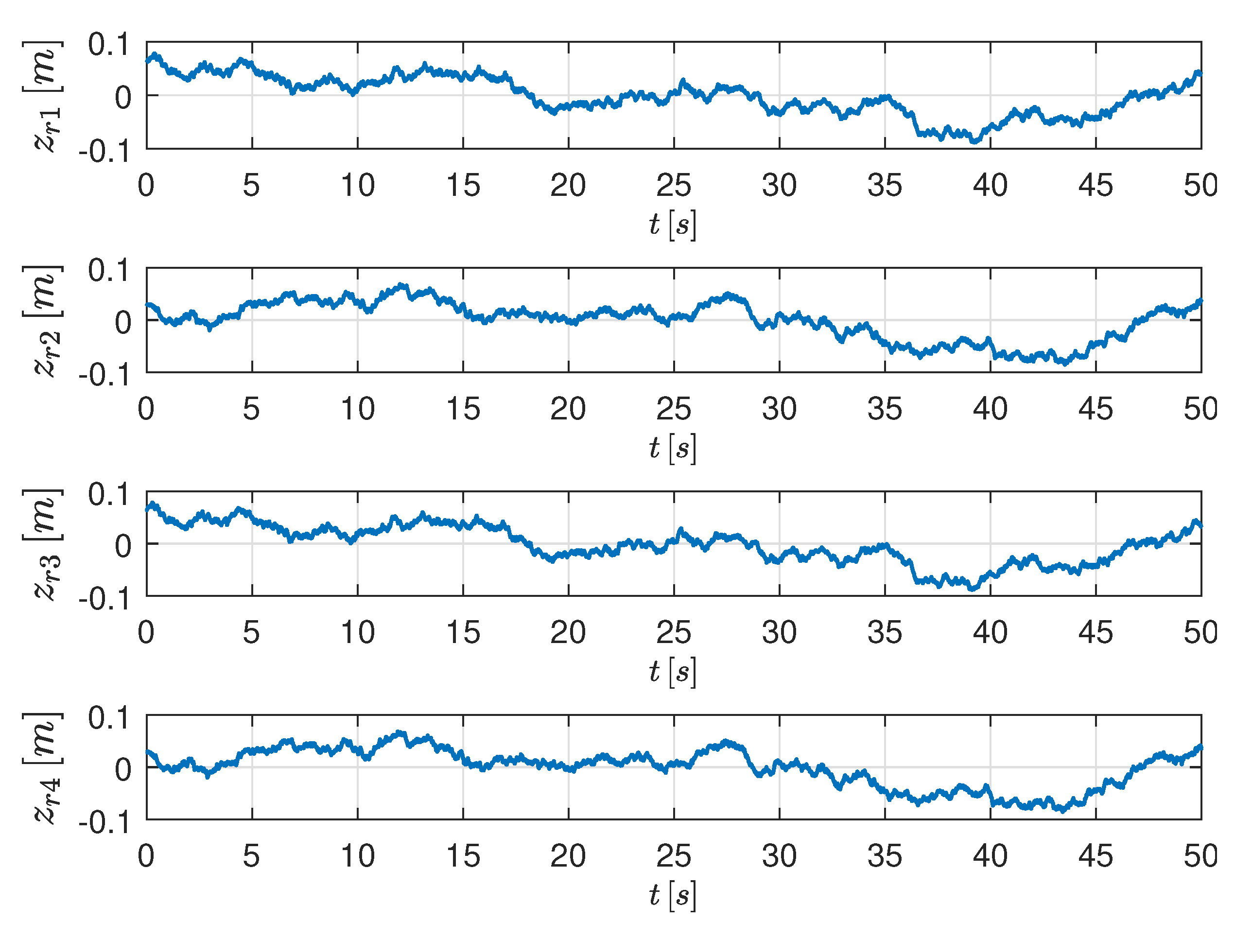
Road’s profiles complying with the ISO-8608 standard [
15] have been used in the simulations. In particular, all simulations have been undertaken by assuming to drive on a
C straight road at 70 Km/h.
Figure 5 depicts the corresponding profiles.
The same standard class-C vehicle and actuator considered in [
3] (where all relevant parameters are listed) is used here.
The following dynamical weights have been used in the three control strategies
with
,
,
and
in (
29) as free design knobs. The fact that the regulation of the Ride Index can be simply achieved by tuning the few control design knobs testifies favorably on the flexibility of the proposed MIPC approach.
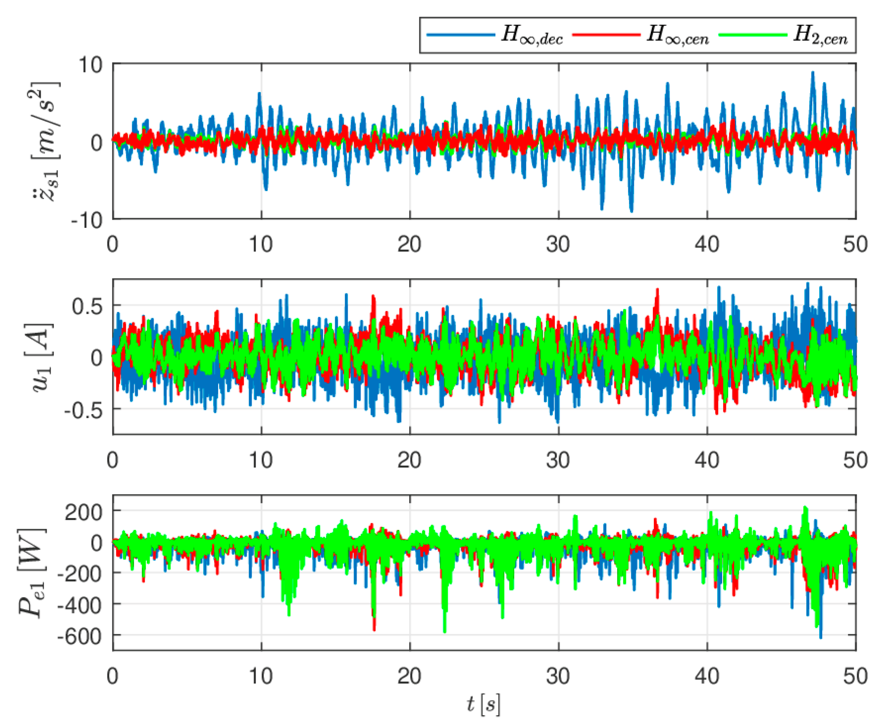
4.1. Simulations for Ride Index = 0.25
The values of design knobs values used in the RI =
simulations are reported in
Table 1 whereas the plots of the acceleration
, actuation current
and the harvested electrical power
under the three control laws are reported in
Figure 6 4.2. Simulations for Ride Index = 0.47
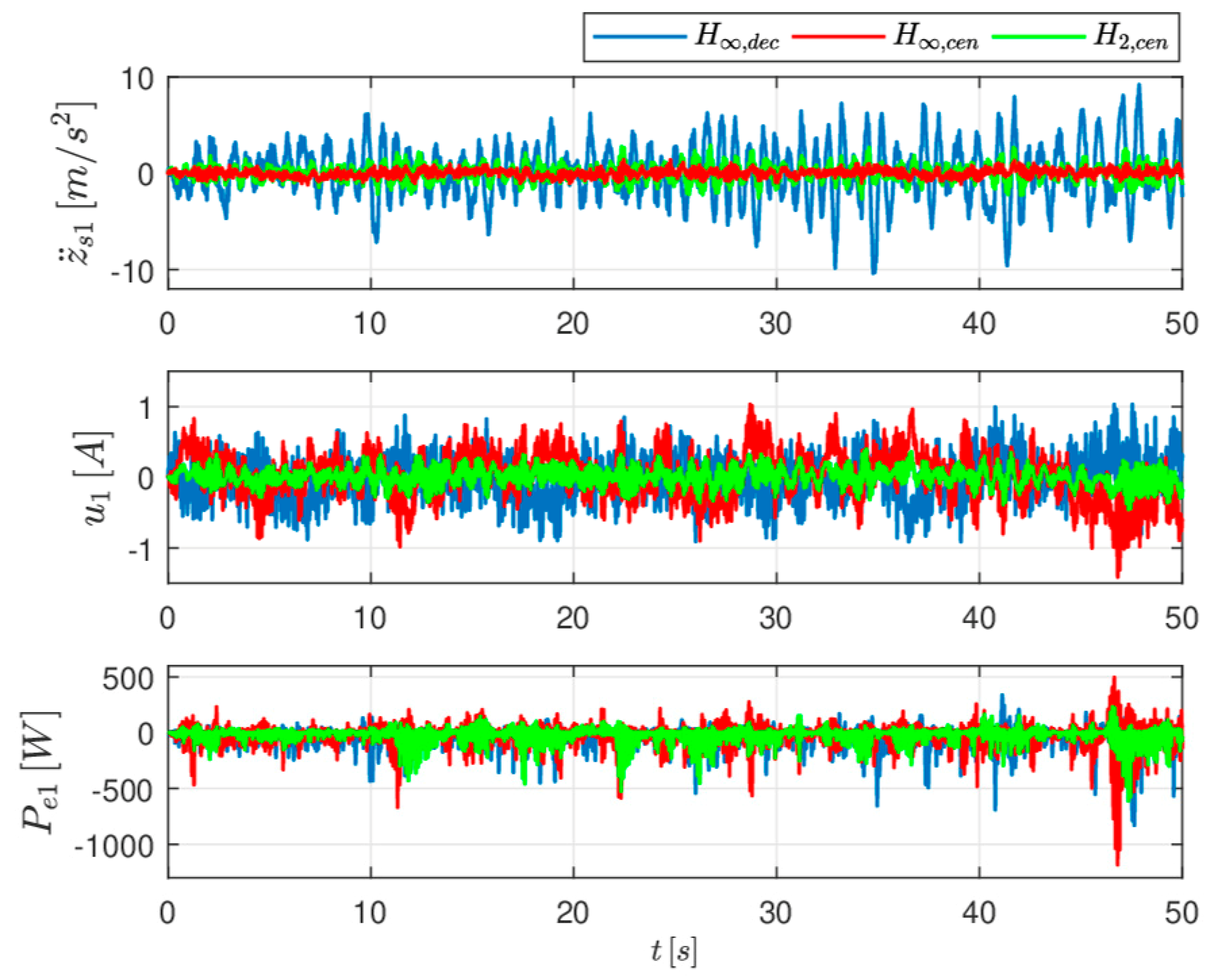
In
Table 2 the design knobs values used in the RI =
simulations are reported while the plots of the corresponding acceleration
, actuation current
and the electrical power
under the three control laws are reported in
Figure 7.
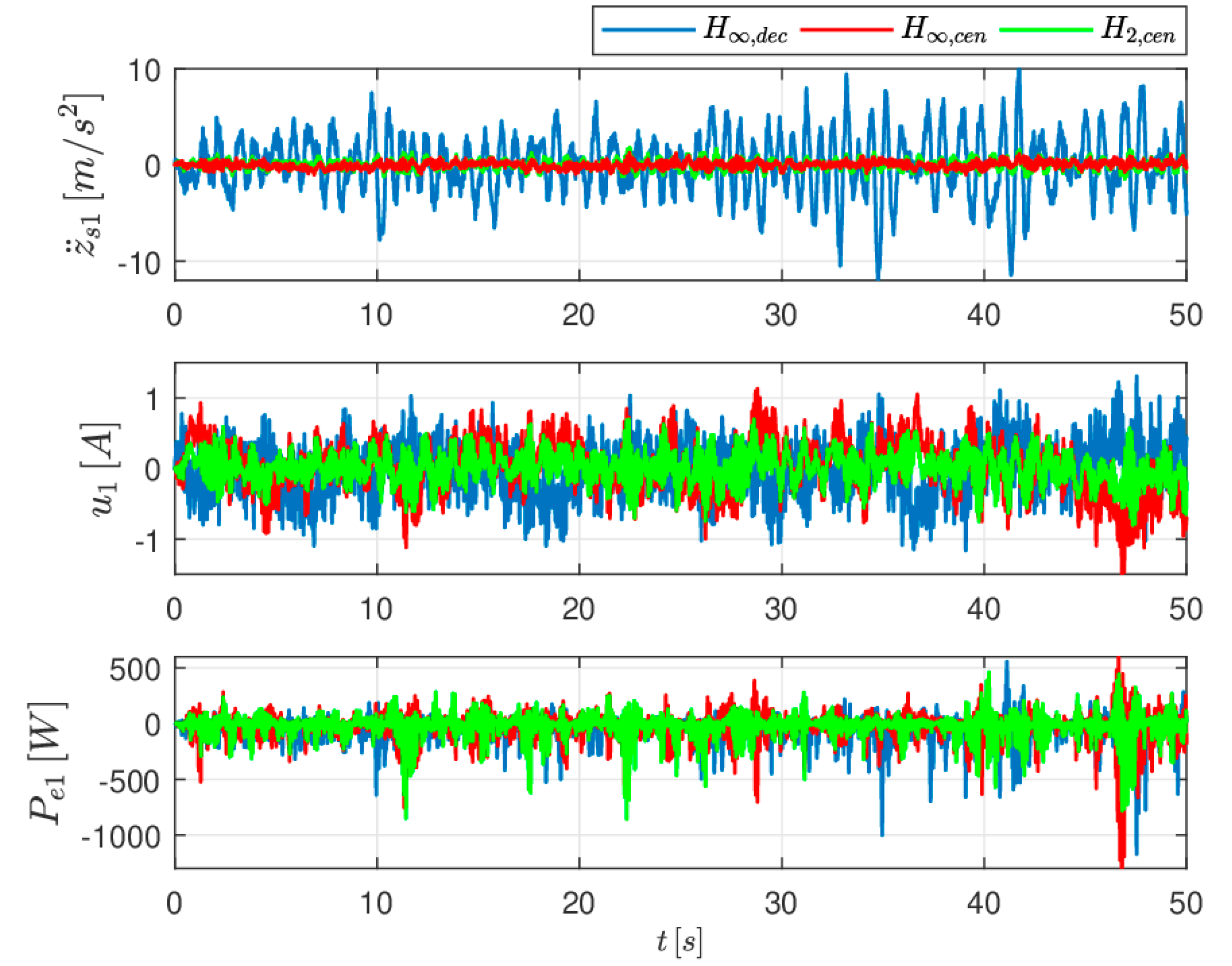
4.3. Simulations for Ride Index = 0.70
Finally, in
Table 3 the values of the design knobs used for the case RI =
are reported while the plots of the acceleration
, actuation current
and the harvested electrical power
under the three control laws are reported in
Figure 8.
4.4. Average Harvested Electrical Power
Finally, next
Table 4 summarize the average harvest electrical power during the simulations.
From the simulation it results that the H
and H
regulators, designated on the basis of the full-car suspension model, guarantee good rider performance and higher levels of harvested energy with respect to the H
controller in all the situations tested. Moreover, the ride comfort performance of the H
regulator, designated on the basis of the quarter-car suspension model and implemented in a decentralized way, degrades remarkably at the increase of the energy harvesting requirements. This can be seen from the accelerations
plots but similar conclusions can be drawn out by observing the sprung mass accelerations
and the pitch and roll angles evolutions (non reported here for space limitations but available in [
13]).
As far as the amount of harvested energy during the simulations,
Table 4 allows one to observe that the centralized H
and H
regulators always are able to recover more energy than the decentralized H
controller, the more at lower values of the RI index. Moreover, it can be seen that the H
regulator recovers the largest amount of electric power, while the H
regulator is more robust in rejecting the exogenous signals acting to the system.
5. Conclusions
The usage of regenerative suspension systems in modern electrical/hybrid cars could contribute to the vehicle’s autonomy with a modest degradation to the usual ride comfort and road handling performance. The integration of such systems with other existing energy harvesting devices, such as regenerative brakes, may help the diffusion of this kind of cars, providing together a total amount of many tens/hundreds watts.
This paper has complemented the results achieved in [
3] on the design of active control laws for the regulation of regenerative suspension systems by extending the scalar MIPC approach there presented for a quarter-car system to the general multivariable solution achieved on the basis of a full-car model. Moreover, both the
and
state-feedback solutions have been considered based on a novel and
ad-hoc state-space realization and have been shown to be enough flexible and powerful to easily trade-off amongst conflicting energetic and dynamic requirements.
From the simulations it results that the centralized solutions have to be preferred with respect to the decentralized one. In fact, from
Table 4 it results that the improvements on the harvested energy are increasingly higher (up to
for the centralized
and up to
for the centralized
optimal controllers) as the ride index RI decreases. This is especially important in the large part of cars usage, where maintaining low values of the ride index is of paramount importance for ensuring a good ride comfort. It is also found that the centralized
control is able to gain the double of the energy harvested by the centralized
control for the same value of the ride index.
An important contribution of this work is the demonstration that the coordination of the control actions achievable by a multivariable design has to be preferred than a simpler decentralized implementation. The usage of modern and multi-objective control design methodologies make the extra numerical complexity for the multivariable design negligible.
Author Contributions
Methodology, supervision and writing-review and editing A.C.; Investigation and formal analysis F.T.; Software, data curation, visualization and writing-original draft preparation P.V. All authors have read and agreed to the published version of the manuscript.
Funding
This research received no external funding.
Conflicts of Interest
The authors declare no conflict of interest.
References
- Abdelkareema, M.A.A.; Xua, L.; Alia, M.K.A.; Elagouza, A.; Mia, J.; Guoa, S.; Liuc, Y.; Zuoc, L. Vibration energy harvesting in automotive suspension system: A detailed review. Appl. Energy 2018, 229, 672–699. [Google Scholar] [CrossRef]
- Zhang, R.; Wang, X.; John, S. A Comprehensive Review of the Techniques on Regenerative Shock Absorber Systems. Energies 2018, 11, 1167. [Google Scholar] [CrossRef]
- Casavola, A.; di Iorio, F.; Tedesco, F.; Multiobjective, A. H∞ Control Strategy for Energy Harvesting in Regenerative Vehicle Suspension Systems. Int. J. Control 2018, 91, 741–754. [Google Scholar] [CrossRef]
- Casavola, A.; di Iorio, F.; Tedesco, F. Gain-scheduling control of electromagnetic regenerative shock absorbers for energy harvesting by road unevenness. In Proceedings of the 2014 IEEE American Control Conference, Portland, OR, USA, 4–6 June 2014. [Google Scholar]
- Sultoni, A.I.; Sutantra, I.N.; Pramono, A.S. H∞ Multi-Objective Implementation for Energy Control of Electromagnetic Suspension. Int. Rev. Mech. Eng. 2015, 9, 542–547. [Google Scholar] [CrossRef]
- Kim, C.; Ro, P.I. An Accurate Full Car Ride Model Using Model Reducing Techniques. J. Mech. Des. 2002, 124, 697–705. [Google Scholar] [CrossRef]
- Kecik, K.; Mitura, A.; Lenci, S.; Warminski, J. Energy harvesting from a magnetic levitation system. Int. J. Non-Linear Mech. 2017, 94, 200–206. [Google Scholar] [CrossRef]
- Sammier, D.; Sename, O.; Dugard, L. Control of Active Vehicle Suspensions. In Proceedings of the IEEE International Conference on Control Applications, Anchorage, AK, USA, 25–27 September 2000. [Google Scholar]
- Poussot-Vassal, C.; Sename, O.; Dugard, L.; Gáspár, P.; Szabó, Z.; Bokor, J. A new semi-active suspension control strategy through LPV technique. Control Eng. Pract. 2008, 16, 1519–1534. [Google Scholar] [CrossRef]
- ISO. ISO 2631-4: Human Exposure to Mechanical Vibration and Shock. Part 4: Guidelines for the Evaluation of the Effects of Vibration and Rotational Motion on Passenger and Crew Comfort in Fixed-Guideway Transport Systems; International Organization for Standardization: Geneva, Switzerland, 2001. [Google Scholar]
- Chen, H.; Guo, K.H. Constrained Control of Active Suspensions: An LMI Approach. IEEE Trans. Control Syst. Technol. 2005, 13, 412–421. [Google Scholar] [CrossRef]
- Rajamani, R. Vehicle Dynamics and Control, 2nd ed.; Springer: Berlin, Germany, 2012. [Google Scholar]
- Vaglica, P. Modeling and Control of Regenerative Suspension Systems for Automobiles. Master’s Thesis, University of Calabria, Rende, Italy, 2019. [Google Scholar]
- Boyd, S.; El Ghaoui, L.; Feron, E.; Balakrishnan, V. Linear Matrix Inequalities in System and Control Theory; Society for Industrial and Applied Mathematics: Philadelphia, PA, USA, 1994; Volume 15. [Google Scholar]
- ISO. ISO 8608:1995(E): Mechanical Vibration—Road Surface Profiles—Reporting of Measured Data; International Organization for Standardization: Geneva, Switzerland, 1995. [Google Scholar]
© 2020 by the authors. Licensee MDPI, Basel, Switzerland. This article is an open access article distributed under the terms and conditions of the Creative Commons Attribution (CC BY) license (http://creativecommons.org/licenses/by/4.0/).


