1. Introduction
Transmission loss (TL) is an acoustic parameter which is widely used throughout industry and research applications. It is a measure of the ratio of incident to transmitted acoustic sound power levels, as described in Equation (1) [
1]:
The frequent use of TL over other measurement parameters such as insertion loss (IL) or level difference (LD) is due to the independence of the source impedance and end conditions of the setup. Naturally, TL is a common measurement parameter used for validation purposes as it will characterize the damping device exclusively. However, this paper will highlight that the assumption of source and system independence should be taken with caution, considering that the effect of incident acoustic pressure amplitudes on the transmission loss of damping devices can be easily overlooked. The effect of incident acoustic pressure amplitude may be crucial when attempting to extrapolate the transmission loss measured in an experimental setup to that which is estimated for an industrial setting.
This paper focuses on the TL of the Helmholtz resonator (HR), a device that is ubiquitous in research because of its geometric simplicity and ability to target low frequencies while maintaining relatively small dimensions [
2,
3,
4]. The HR consists of an enclosed cavity with a protruding neck that connects it to the system of interest. The HR is often understood using a lumped-parameter method, which draws an analogy between the HR and a dynamic vibration absorber. At its resonant frequency, the mass of fluid in the neck oscillates while the fluid in the cavity volume compresses and rarefies, acting as a spring. Damping within the HR consists of radiation losses from the neck and viscothermal losses at the walls of the neck [
5]. Additionally, “jet-flow” occurs at the neck during high-amplitude excitation, which results in increased energy losses due to viscothermal effects, providing an additional source of damping [
6]. Excitation amplitude and the resulting jet-flow have been considered with respect to their effects on the acoustic resistance of an HR [
7]. However, the effects of the additional damping at high amplitudes have not been considered from the perspective of transmission loss. Therefore, this paper focuses on clarifying the effects of pressure amplitude on the transmission loss of HRs with various geometries. Accordingly, the use of transmission loss as a measurement parameter may not necessarily be the best method to quantify the acoustic performance for all damping devices.
2. Experimental Setup and Methodology
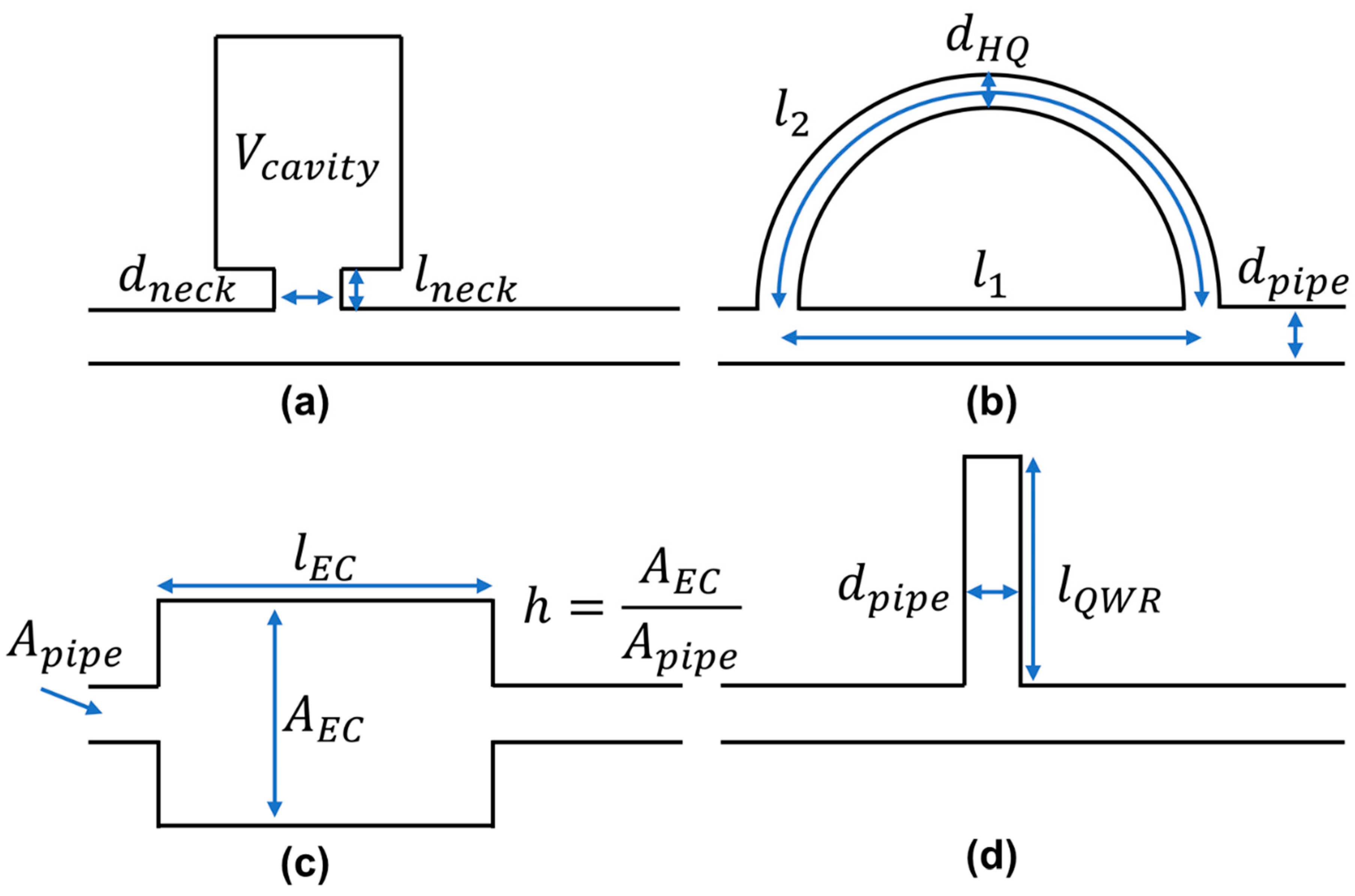
The experimental setup and methodology utilized here will be described in this section. The transmission loss is measured for various passive damping devices such as a Helmholtz resonator (HR), Herschel–Quincke (HQ) tube [
8,
9], expansion chamber (EC), and a quarter wave resonator (QWR) [
10] under no-flow conditions. A schematic of the formerly mentioned damping devices are illustrated in
Figure 1. The experimental setup was constructed to study a variety of parameters related to using passive damping devices for a specific nuclear application [
11,
12,
13,
14,
15,
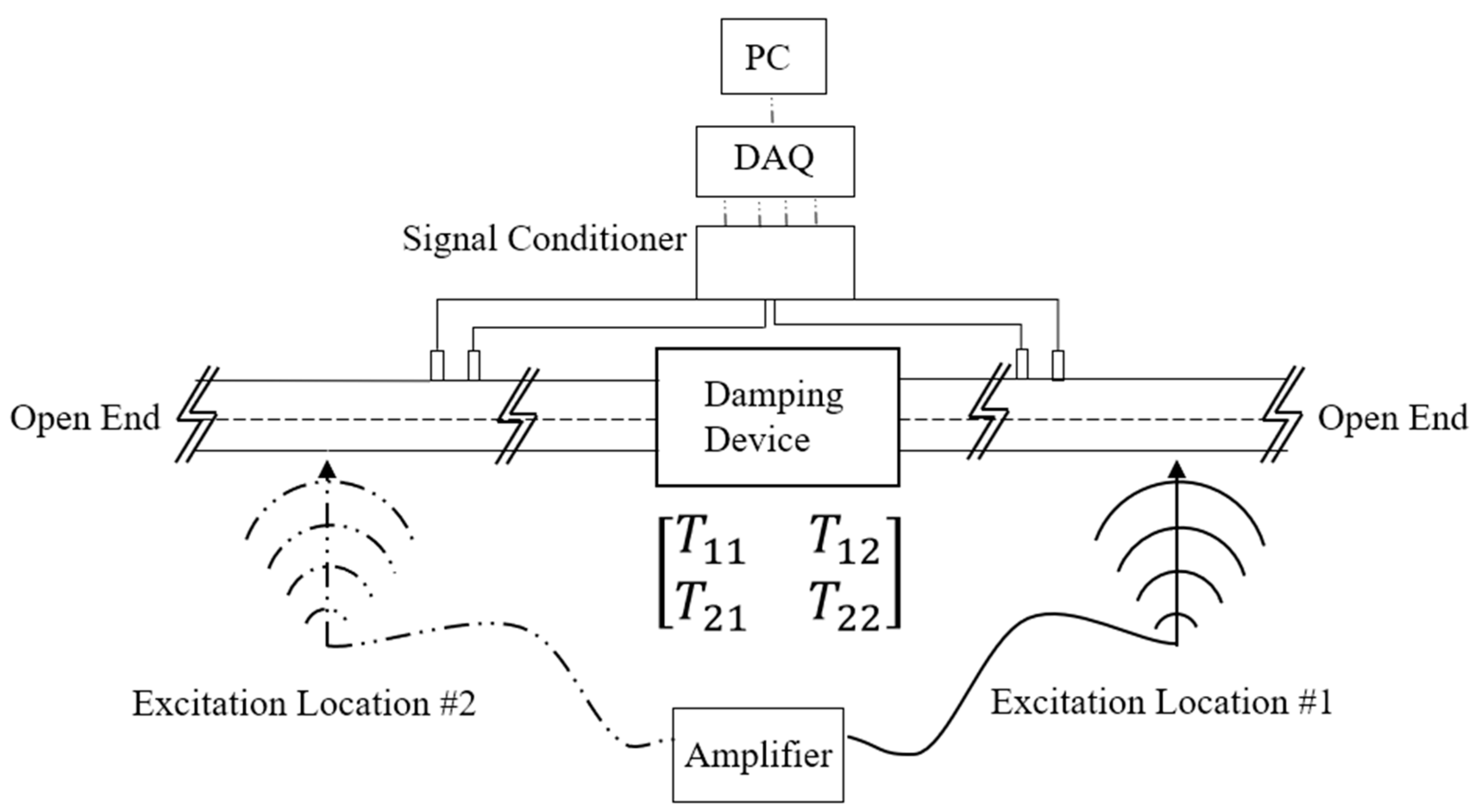
16]. The current paper will highlight the measurement of transmission loss of passive damping devices applied to a piping system with a simplified schematic presented in
Figure 2. The incident acoustic pressure amplitude and the damping device geometric parameters (e.g., HR neck length) are the control variables. The piping system is 101.5 mm (4”) in diameter with a total pipeline length of 5.03 m (198 inches). The reflections at the end terminations of the pipeline are considered as open ends. The damping devices are tuned for 150 Hz which is one of the anti-resonant frequencies of the piping system. However, additional experiments were conducted for a resonant piping system where the piping system length was changed to 5.59 m (220 inches) corresponding to a frequency of resonance of 150 Hz for the 5th acoustic mode. The results for the transmission loss measurements were nearly identical for both the travelling wave system and resonant system tests. The acoustic pressure was captured using four ¼” pressure microphones distributed in two pairs on either end of the damping device. The microphone spacing of each pair is 196.85 mm (7.75 inches) which corresponds to a cut-off frequency of approximately 873 Hz. This is less than that of the cut-off frequency determined by the plane-wave limit which is defined by the largest diameter pipe within the pipeline (1980 Hz) [
17]. The measurement range for the current work focuses on the frequency range of 50–500 Hz.
Transmission loss is obtained in this work by experimentally determining the acoustic transformation matrix. The two-source location method developed by Munjal [
18] is utilized here whereby two separate pairs of acoustic pressure microphones are placed on either end of the damping device as shown in
Figure 2. An initial trial with a white noise excitation source is conducted at location #1 and a second trial is conducted with the excitation source moved to location #2. The processing of the two datasets consists of obtaining an array of transfer functions for each excitation source configuration. These two sets of transfer functions are utilized concurrently to calculate the four elements of the transformation matrix. The transfer matrix elements define the relationship between the upstream and downstream acoustic pressure and volume velocity. Equation (2) illustrates this mathematically by describing the state variables in matrix format where
and
represent the acoustic pressure and volume velocity while subscripts
u and
d represent the locations upstream and downstream of the test element, respectively. For example,
relates the upstream acoustic pressure to the downstream acoustic pressure while
relates the upstream volume velocity to the downstream volume velocity.
Finally, the transmission loss of the damping device is calculated using Equation (3) below:
where
ρ is the fluid density,
is the speed of sound,
is the cross-sectional area of the pipe. This procedure is performed for several different damping devices with the aim of understanding the response when varying the excitation source electrical power. The change in input power supplied to the source will control the incident acoustic pressure amplitude.
3. Results and Discussion
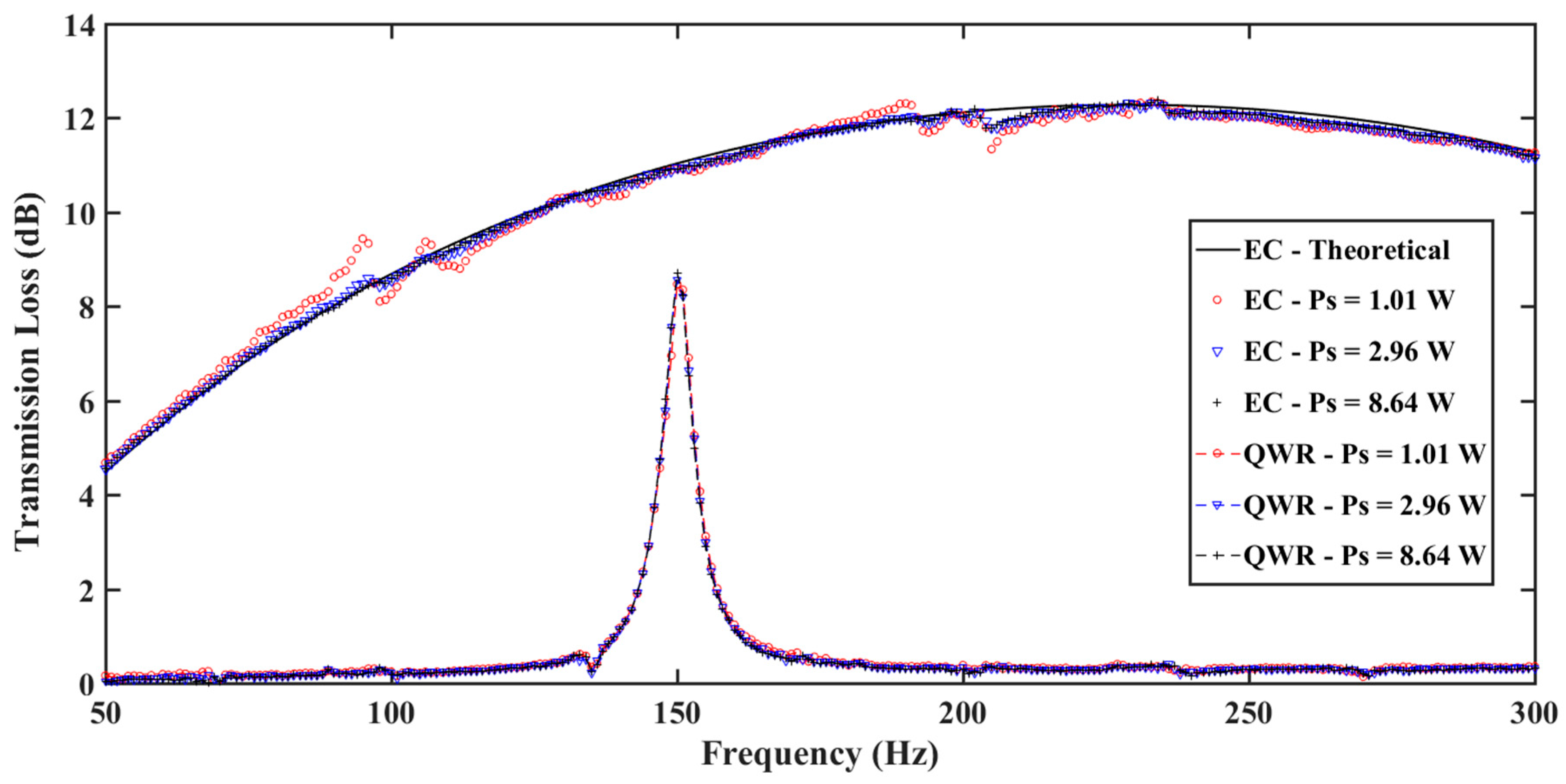
It is quite commonly assumed in the literature that transmission loss is a parameter which is source independent. This implies that regardless to the power of the acoustic source, the transmission loss measurement will remain constant. To begin clarification of this behaviour, the experimental measurement of the transmission loss spectra was first conducted for three reactive damping devices: an expansion chamber (EC), a quarter wave resonator (QWR) and a Herschel–Quincke (HQ) device.
Figure 3 illustrates the transmission loss spectra for the EC and the QWR while
Figure 4 shows the transmission loss spectra for an HQ device. As a form of validation, the transmission loss spectra for the EC is also compared to that which is theoretically defined in Equation (4) [
19]. Here,
is the ratio of cross-sectional area of the EC,
is the length of the EC, and
is the wavenumber. A good agreement is present between the measured and theoretically obtained values.
In both
Figure 3 and
Figure 4, the power of the source was varied from 1.01 W to 8.64 W. For all variations of the source power, it is clear that there is minimal to no effect on the transmission loss peak value. It is clear that the behaviour is consistent with the current understanding of the nature of the transmission loss parameter. That is, that the transmission loss spectra is independent of the incident acoustic pressure amplitude.
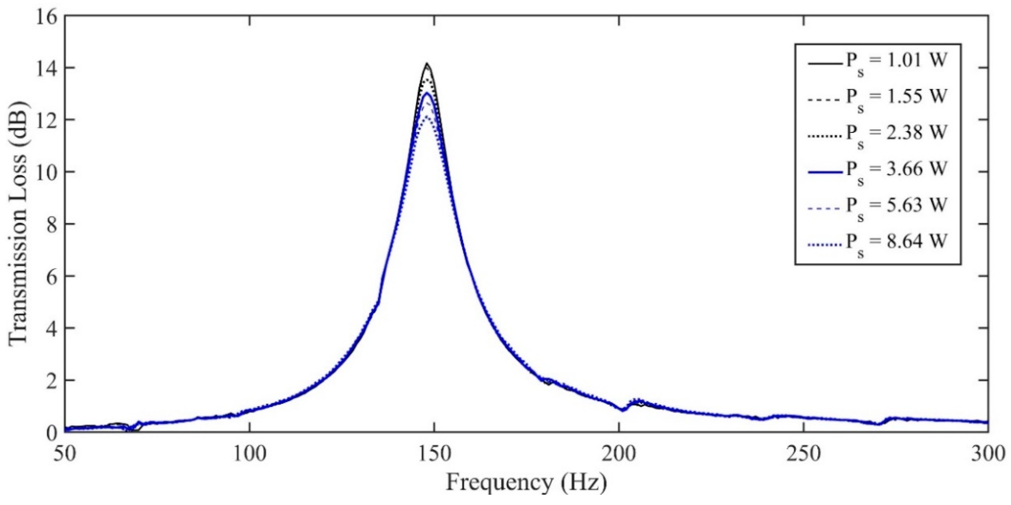
However, as
Figure 5 shows, the transmission loss peak for a 1 L volume Helmholtz resonator (HR), with a neck length of 1.5”, is dependent upon the power supplied to the source. It is interesting to note that the peak frequency of transmission loss is unaffected, but that the magnitude of the peak changes with input power. As the input source power increases from 1.01 W to 8.64 W, the transmission loss peak decreases from over 14 to nearly 12 dB. This is attributed to the jet-flow effect at the neck, which becomes prominent at high pressure amplitudes and increases the acoustic resistance of the HR. The increased damping within the HR at high incident pressure amplitudes results in a reduction in its effectiveness on the main system. This can be understood considering the analogy between an HR and a vibration absorber. At its resonant frequency, an undamped vibration absorber will provide maximal damping for the main system. The presence of damping within the absorber decreases its effectiveness at this frequency, but increases the frequency range over which it is effective. Similarly, the increase in energy losses caused by jet-flows at high pressure amplitudes results in a decrease in the effectiveness of the HR for attenuating noise within a pipeline at its natural frequency.
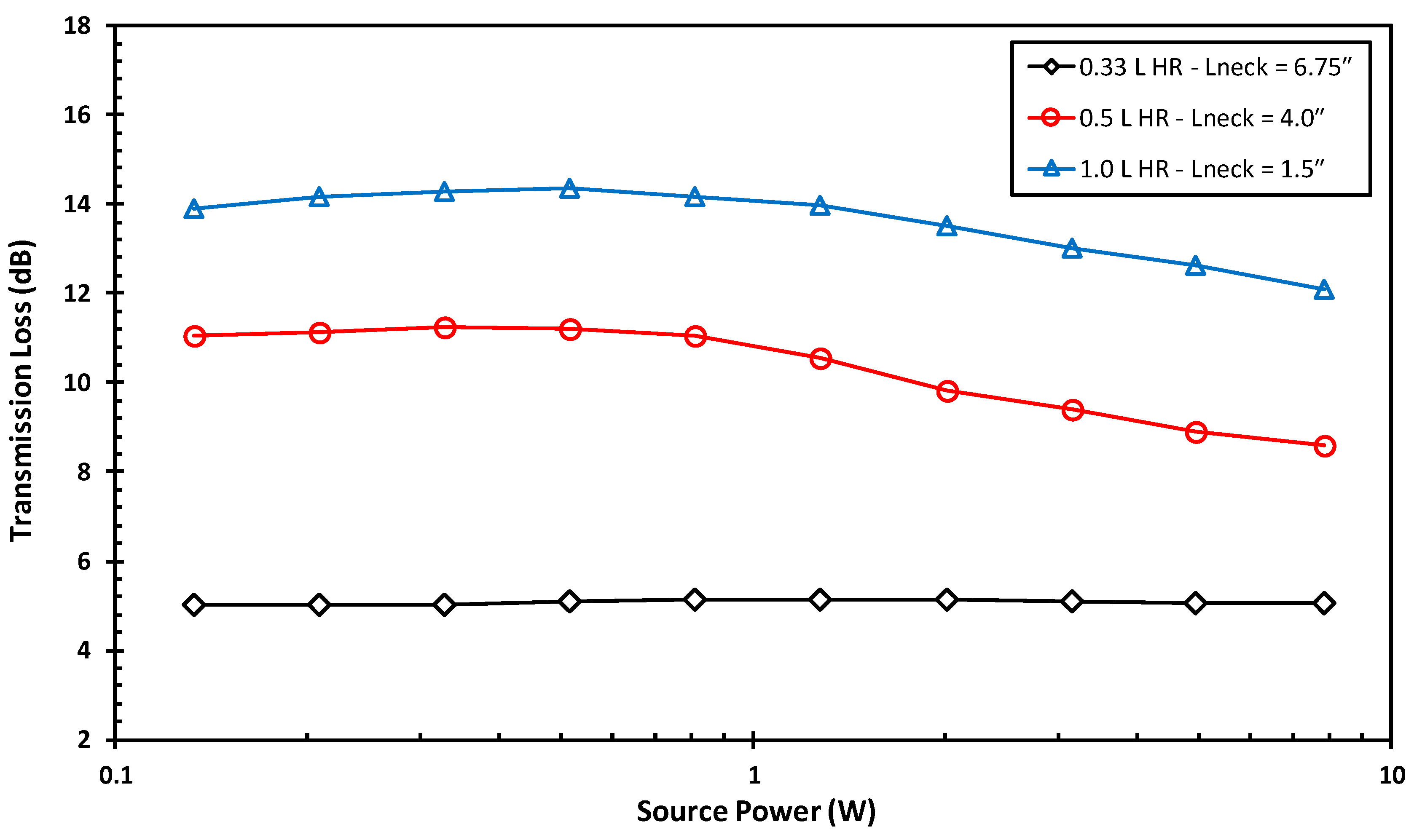
Additional TL measurements were taken for 0.33 L and 0.5 L volume HRs, which have neck lengths of 6.75” and 4”, respectively. For the sake of comparison, the neck diameter of all HR devices was kept constant and all resonators were tuned to target the same frequency of 150 Hz. The transmission loss peaks for the different HR sizes were extracted at various source power levels, as shown in
Figure 6. It can be seen that for source power levels up to approximately 1 W, the transmission loss is relatively constant. However, as the source power is further increased, the TL of the HRs with 1.5” and 4” neck lengths decrease with increasing source power. Both experience a reduction of approximately 2 dB in peak attenuation over the tested range of input power. Notably, the HR with a 6.75” neck length maintains a nearly constant peak attenuation of close to 5 dB. This is because longer neck lengths are less prone to the jet-flow effect and the increased losses that arise therefrom. Accordingly, it can be said that the peak TL of HRs with short to intermediate neck lengths is sensitive to the magnitudes of acoustic source excitation. This has implications regarding the “source independence” of transmission loss as a measurement technique, especially for scaling the performance of an HR from a test setup to its system of intended application.
The change in peak attenuation for HRs with relatively short necks shows that transmission loss is not entirely source independent. Accordingly, it is important to consider the effects of source excitation amplitude when evaluating the acoustic damping of an HR, especially those with short to intermediate neck lengths. In fact, excitation amplitude should be considered for any device that consists of one or more orifices, since it will be prone to jet-flows and the associated losses at high pressure amplitudes. It is therefore recommended to evaluate the transmission loss for these damping devices at acoustic pressure levels similar to those in the system for which the device is intended. Alternatively, the TL can be measured at multiple excitation amplitudes, so that a plot similar to that of
Figure 6 is obtained. The TL at an excitation level outside of the tested range can then be approximated.
4. Conclusions
The effect of incident acoustic pressure amplitudes on the transmission loss of several different passive damping devices was studied. Experimental measurements were conducted to determine the transmission loss of the damping devices with various input power levels to the acoustic source. For Helmholtz resonators with sufficiently short necks, a “jet flow” effect is present at high acoustic pressures which causes a change in the observed transmission loss as the source power is varied. For research and application purposes, it is advised that an HR should be tested at the acoustic pressure amplitudes which are expected in the system which is targeted for implementation. Furthermore, the use of any acoustic damping devices comprising of one or more orifices will be sensitive to the effects of acoustic pressure amplitude. The assumption of the source independence of transmission loss measurements must therefore be taken with caution, considering that varying the input power level of the acoustic source may, in fact, affect the acoustic response of a device.
