Study on Dynamic Interaction of Railway Pantograph–Catenary Including Reattachment Momentum Impact


1
National Rail Transit Electrification and Automation Engineering Technique Research Center, Southwest Jiaotong University, Chengdu 611756, China
2
Department of Structural Engineering, Norwegian University of Science and Technology, 7491 Trondheim, Norway
*
Author to whom correspondence should be addressed.
Vibration 2020, 3(1), 18-33; https://doi.org/10.3390/vibration3010003
Submission received: 17 August 2019
/
Revised: 29 January 2020
/
Accepted: 6 February 2020
/
Published: 11 February 2020
Abstract
:The pantograph–catenary system is responsible for the electric transmission to the locomotive via the sliding contact between the pantograph head and the contact wire. The separation of the pantograph head from the contact wire is the main source of arcing, which challenges the normal operation of an electrified railway. To properly describe the contact loss procedure using simulation tools, a mathematical model of the reattachment momentum impact between the pantograph head and the contact wire is proposed in this paper. The Euler–Bernoulli beam is adopted to model the contact and messenger wires, which are connected by lumped mass-spring droppers. The Lagrange multiplier method is utilised to describe the contact between the pantograph head and the contact wire. The momentum impact generated during the reattachment process is derived based on the principle of momentum conservation. Through several numerical simulations, the contact wire uplift and the contact force are evaluated with the reattachment impact. The analysis result indicated that the velocities of the contact wire and the pantograph head experience a sudden jump at the time instant of reattachment, which leads to a sudden increase of the contact force. When the reattachment impact is included, the maximum value and the standard deviation of contact forces show a significant increase. The effect of reattachment impact is more significant with the increase of the pantograph mass and stiffness.
1. Introduction
In electrified railway industries, the catenary and pantograph are widely used for transmitting the electrical energy to the locomotives. With the increase of the train speed, the vibration of the catenary–pantograph becomes stronger, which increases the fluctuation of the contact force. The frequent contact loss between the pantograph head and the contact wire has been one of the technical issues challenging the current collection quality, as it is the main source of electric arcing and the interruption of the power transmission. Normally, the contact loss is caused by inadequate contact force. Thus, the contact force should be stable, and the contact loss should be avoided to ensure continuous contact of the pantograph and the catenary.
To improve the current collection quality of the pantograph–catenary, many scholars have made significant contributions to improving the understanding of the pantograph–catenary dynamics. The relevant study has been reviewed in [1], in which an overview of the mathematical methods of modelling the catenary–pantograph system has been given. Various internal and external disturbances (such as the wind load [2,3], the vehicle vibration [4], the wave propagation [5] and the aerodynamic instability [6]) to the pantograph–catenary system have also been investigated to improve the robustness of the system. The methods of modelling the pantograph–catenary contact have been briefly reviewed in [7], in which the influence of different contact models on the catenary–pantograph dynamic response has been revealed. In [8], the results of nine pantograph–catenary models are compared to establish a world benchmark for the validation of simulation tools. At present, the most prevalent method to model the sliding contact of the pantograph and the catenary is the “penalty function method”, in which, the contact between the pantograph head and the contact wire is defined through an assumption of “contact stiffness”. The contact force is calculated based on the interpenetration between the pantograph head and the contact wire. This method is first introduced to model the pantograph–catenary contact by Collina and Bruni [9]. The penalty function method is developed and gradually becomes the dominant approach to model the contact of pantograph–catenary, as it is convenient to be included in the stiffness matrix [10]. Ambrósio et al. [11] present a modified penalty function method using the relative velocities of the two contact bodies. Based on this model, a co-simulation of finite element and rigid multi-body dynamic codes is performed, and the influence of the environmental wind on the pantograph–catenary current collection is investigated in [12,13]. In [14], the ACNF (absolute nodal coordinate formulation) method is adopted to model the catenary. The interface between the contact wire and the pantograph is described as a spring-damper model, in which the contact loss is assumed by the compression force. In [15], the non-linearity of the catenary is considered by a non-linear finite element approach, and its interaction with the pantograph is developed by the penalty function method. A moving mesh method is developed to improve computational efficiency [16]. However, the penalty function method may not describe the realistic contact condition between the pantograph head and the contact wire, because an assumption is defined that the two contact bodies can penetrate each other. Therefore Seo et al. [17] and Lee [18] use the Lagrange multiplier method to model the interaction between the pantograph and the catenary, which excludes the penetration assumption and obtained more reasonable results.
The Lagrange multiplier method is widely used in studies of moving load problems [19]. Lee [20,21] firstly proposes a method to describe the separation between the moving mass and the beam. Subsequently, Ouyang et al. [22,23], Dahlberg [24], Cheng et al. [25] and Lee et al. [26,27] expand this idea to different application backgrounds. According to [25], after the separation between a mass and a beam, the reattachment may produce a momentum impact on the beam, which may result in a sudden jump of the velocity of the beam. Stăncioiu et al. [22] develop a simple model for the reattachment impact and investigate its influence on the dynamic behaviour of the moving mass-beam system. The results show that in some numerical examples, the impact on reattachment has a significant effect on the dynamic response.
As is well known, the contact loss of the pantograph and the catenary is the main source of the deterioration of the current collection quality. To properly describe the separation and reattachment of the pantograph head and the contact wire is of great importance for understanding the pantograph–catenary dynamics. To the authors’ best knowledge, no studies have ever been undertaken to describe the separation and the reattachment for the pantograph–catenary. This shortcoming is tackled in this paper. A contact model of the pantograph–catenary is presented based on the Lagrange multiplier method. The contact is described in terms of constraint equations so that the contact loss can be fully described. The impact of the pantograph head on the contact wire at the reattachment point is considered by introducing additional velocity into the contact wire. Then, some numerical simulations at higher speed are performed to analyse the pantograph–catenary interaction considering the reattachment impact.
2. Modelling of Pantograph–Catenary with Reattachment Impact
Normally, a railway catenary is comprised of two tensioned cables called messenger wire and contact wire. The contact wire directly contacts with the pantograph head to transmit electricity to the locomotive. The messenger wire is used to hang the contact wire to keep it level. The two wires are connected via several droppers. In this section, the equation of motion for the pantograph–catenary is derived. To properly describe the high-frequencies behaviour, the beam element with bending stiffness is adopted to model the contact and messenger wires [28]. Then a contact model is developed including the momentum impact during the reattachment process.
2.1. Equation of Motion for Catenary
The description of the catenary with a moving contact force is shown in Figure 1. v denotes the speed of the contact force traversing along the contact wire. and represent the tensions of the messenger wire (the upper beam) and the contact wire (the lower beam), respectively. The equation of motion for the messenger wire can be described by:
Similarly, the equation of motion for the contact wire can be expressed by:
In Equations (1) and (2), and denote the linear densities of the messenger and contact wires, respectively. and denote the flexural rigidities of both wires. and are the corresponding damping for both wires. L denotes the total length of one section. is the Dirac delta function. and are the deflections of the messenger wire and the contact wire, respectively. and are the forces of the ith dropper acting on both wires at the point . is the force of the jth steady arm acting on the messenger wire at the point . is the force of the jth registration arm acting on the contact wire at the point . and are the mass and stiffness of the ith dropper, which can only work in the traction condition. and are the mass and stiffness of the jth steady arm, respectively. is the mass of the jth steady arm. nd, nt and nr are the total numbers of droppers, messenger wire supports and steady arms, respectively. The last equations in Equations (1) and (2) define the constraint conditions for each wire.
In this work, the modal superposition method is adopted to solve Equations (1) and (2). The beam deflection can be represented in a modal expansion as [5]:
where, and are the modal coordinates for the nth modal function of the messenger/contact wire , which is determined by the constraint conditions. The general solution for the Euler–Bernoulli beam is:
in which, , , , , and are determined by the boundary conditions. As the messenger and contact wires can be assumed to be simply-supported beams [29], it is obtained that,
Thus (n = 1, 2, 3, ……). Substituting Equation (3) into Equations (1) and (2) yields the equation of motion for the catenary concerning the generalised coordinates and .
2.2. Contact Model of Pantograph–Catenary
As shown in Figure 2, the pantograph is considered as a three-stage oscillator with three lumped masses (, , ) connected by three springs with specific stiffness (, , ) and damps (, , ), respectively. The corresponding uplifts of the three masses are , and respectively. F0 is the uplift forces including the aerodynamic effect. The equation of motion for the pantograph is described by:
When the pantograph head contacts with the contact wire, the catenary and pantograph interact with each other by the contact force. However, when the contact loss occurs, the motion of the catenary and the pantograph are independent of each other. The criterion for contact and separation can be governed by the gap of the contact surface as expressed by:
When , the pantograph is separated from the contact wire. If , the pantograph contacts with the contact wire. When the contact occurs, the motion of the contact wire is governed by the following equation:
It can be observed that when the contact occurs, the deflection of the contact wire at the contact point is equal to the displacement of the pantograph head. The contact force is acting on a moving coordinate. The relationship of the acceleration, velocity and displacement at the contact point can be described by:
When the pantograph separates from the contact wire (), the vibrations of the catenary and the pantograph are independent of each other. The equation of motion for the contact wire and the pantograph can be expressed by:
If changes from a positive value to zero, the reattachment occurs, and the pantograph starts to contact with the contact wire. However, as the description in [22], the momentum impact between a mass and a beam during reattachment has a noticeable influence on the dynamic response of the beam. This reattachment impact is modelled in Section 2.3 by introducing an additional velocity in the contact wire during the reattachment.
2.3. Modelling of Reattachment Impact
Consider that the pantograph separates from the contact wire at time instant and reattaches to the contact wire at time instant . During the period , the contact force between the pantograph and catenary is zero. When the reattachment occurs, the equation of motion for the contact wire at time instant due to the reattachment impact is described by:
where, is the impulse caused by the impact of the pantograph head. The equation of motion for the pantograph head (the first mass) can be expressed by:
The influence of the impact is the jump of the velocity of the contact wire at the time instant . By substituting Equation (3) into Equation (11), the contribution of and to the nth mode of the contact wire is expressed by:
Substituting Equation (13) into Equation (11), the equation of motion for the contact wire can be obtained as:
According to the distribution theory [30], the incremental velocities of the pantograph head and the contact wire are determined by the total mass. The velocity jump of the contact wire and the pantograph head from the to can be derived by:
At the reattachment point, the relationship of the velocities of the pantograph head and the contact wire can be expressed by:
in which the high-order term that is neglected in [22] is taken into account here. During the period from to , the assumption is made that the deflection of the contact wire is not changed (namely ). So the following equation can be obtained:
The velocity jump of the contact wire in each mode is:
Solving Equations (14)–(16), p can be derived explicitly as:
Substituting Equation (18) into Equation (17) yields:
The equation of motion for the messenger wire is similar to the contact wire, which can be written by:
Implementing the Lagrange multiplier method, the equation of motion for the pantograph–catenary interaction can be written by:
in which, is the displacement vector of the pantograph–catenary system. and are the corresponding velocity and acceleration vectors. is the restrained displacement vector on the contact surface. is the external force vector excluding the contact force. The constraint condition for Equation (21) is:
which can be extended to:
Equations (21) and (22) can be solved by the direct integration method. Considering a second-order integration through time, the following incremental equation of motion can be obtained as [31]:
where, is the contact force on both of the contact wire and pantograph head. , and are differential operators of second order:
and
in which, and are the coefficients in the integration algorithm. In this paper, a linear acceleration method with and is adopted. At the reattachment point, Equation (18) is adopted to govern the reattachment impact.
3. Analysis with Reattachment Impact
The pantograph–catenary model is established using the parameters in Table 1 and Table 2. The maximum speed is 350 km/h. Higher speeds are adopted in the simulation to reproduce the separation and reattachment between the contact wire and the pantograph head. The influence of the reattachment impact on the pantograph–catenary interaction is investigated. The electromagnetic force caused by the arcing during the separation process is neglected in this work, as it is only a small magnitude of the contact force [32]. Then at different speeds, the separation and reattachment between the pantograph head and the contact wire are analysed. Finally, the influence of the pantograph head parameters on the interaction performance is analysed.
3.1. Analysis with 380 km/h
To reproduce the contact loss between the catenary and the pantograph, the higher speed v = 380 km/h is adopted. The separation between the pantograph and the catenary firstly appears at 42.5 m, (close to the fifth dropper in the first span). The uplift and the velocity of the pantograph head are presented in Figure 3a,b. It is seen that the reattachment impact causes a significant increase of the uplift and the velocity of the pantograph head when the pantograph head re-contacts the contact wire. The velocity of the contact wire at the contact point are shown in Figure 4. As the Lagrange multiplier method is implemented, the uplift of the pantograph head matches the displacement of the contact point in the contact wire. It is seen that the reattachment causes a jump of the velocity of the contact wire. The contact forces are shown in Figure 5. It is also seen that due to the reattachment impact, the contact force experiences a sudden increase from 0 to 400 N within a short time. The impact produces almost excessive 100 N at the peak of the contact force during the reattachment. The overlarge contact force may exceed the safety criterion and damage the contact wire.
3.2. Analysis at Different Operating Speeds
According to the current standard [33], the maximum contact force and the standard deviation of the contact force are the most important indicators to evaluate the current collection quality of the pantograph–catenary system. The maximum contact force should be limited to avoid the potential damage to the catenary. The standard deviation directly describes the fluctuation dispersion of the contact force around its mean value. Figure 6a–c show the maximum contact force, contact force standard deviation and the contact loss percentage at different speeds, respectively. It is found that with the increase of the operating speed, the maximum contact force, the contact force standard deviation and the contact loss rate increase sharply. When the reattachment impact is included, the maximum contact force and the contact force standard deviation are generally larger than the results without the reattachment impact. More contact loss can be observed when the reattachment is included. It is worthwhile noting that the contact force is not filtered with 0~20 Hz to fully describe the contact loss. That is why the standard deviation in Figure 6b is significantly larger than previous works [34]. The presence of the reattachment impact introduces more disturbance to the pantograph–catenary interaction, which increases the maximum contact force, and accordingly increases the fluctuation of the contact force. These also result in more contact losses of the pantograph–catenary interaction.
3.3. Analysis with Different Pantograph Head Parameters
In order to understand the effect of pantograph head parameters on the reattachment impact, a set of simulations is performed with different mass and stiffness of the pantograph head. The contact forces with different M1 are presented in Figure 7 and Figure 8 at 370 km/h and 380 km/h, respectively. In Figure 7a, the contact forces remain unchanged when the reattachment impact is included, as no contact loss occurs. However, with the increase of the pantograph head mass, more contact loss appears, and the difference of the contact forces evaluated by two methods becomes more significant. The similar trend is also observed in Figure 8. When M1 reaches 11 kg, the reattachment impact causes big fluctuations of contact forces. The maximum contact force, the contact force standard deviation and the contact loss with different M1 at 370 km/h and 380 km/h are shown in Figure 9a–c, respectively. It is seen that all these indexes increase when the reattachment impact is included. Equation (18) shows that the increase of the pantograph head mass directly leads to an increase of the reattachment impact. Also, the previous study has revealed that a big pantograph head mass aggravates the current collection quality. The reattachment impact makes this negative effect even bigger.
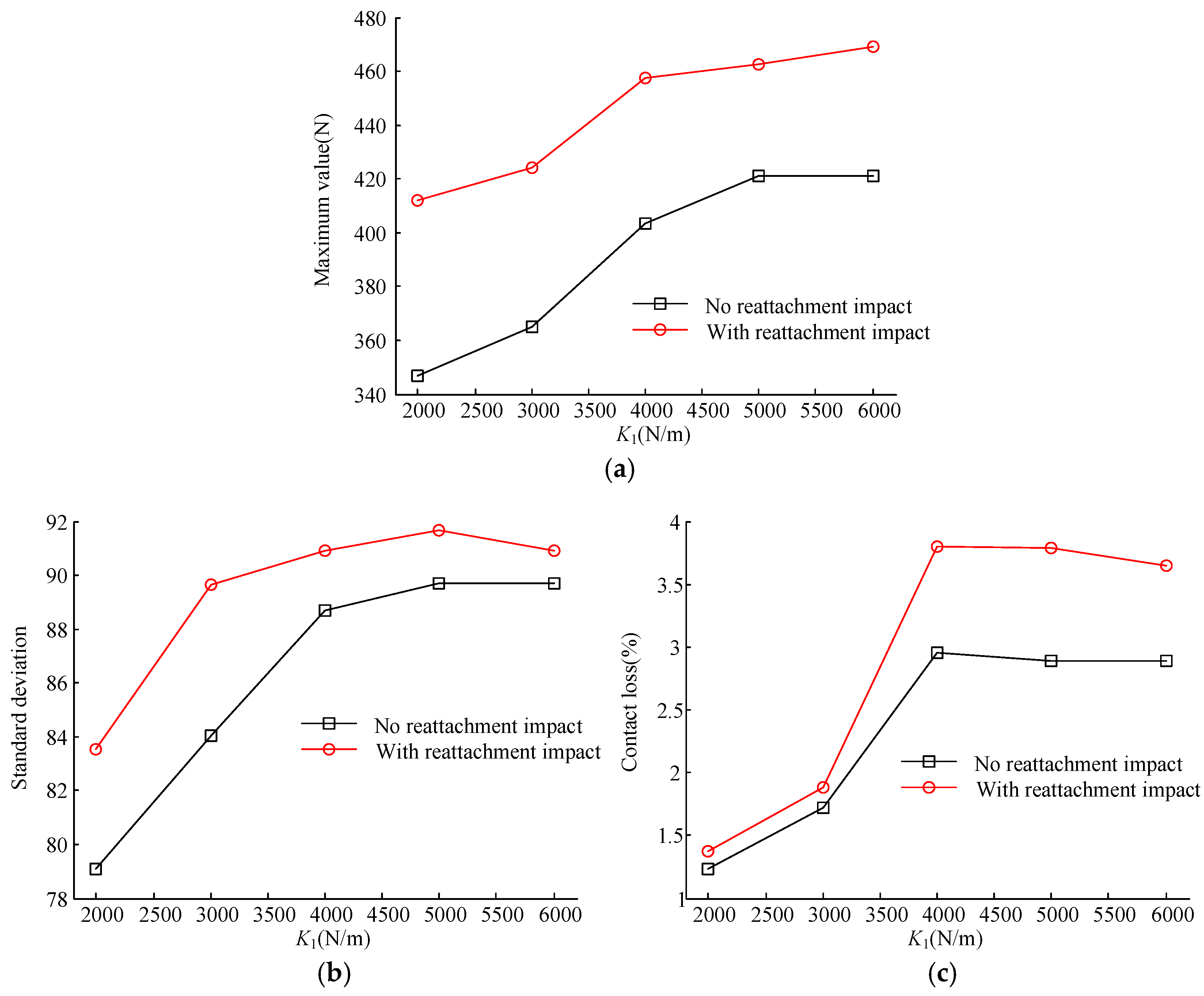
The contact forces with different pantograph head stiffness at 380 km/h are shown in Figure 10. The corresponding statistics are presented in Figure 11. Similar to the influence of M1, when the reattachment impact is presented, the fluctuation in contact force becomes larger and more contact loss can be observed.
4. Conclusions
In this work, the analysis of the interaction of the catenary–pantograph is performed, including the effect of reattachment impact. The additional velocity of the contact wire in each mode caused by the reattachment impact is derived, and its effect is taken into account in the simulation of pantograph–catenary interaction. The effect of the reattachment impact on the interaction performance is investigated with different speeds and pantograph head parameters. The analysis results show that the reattachment impact of the pantograph head can lead to a sudden increase of the velocity for both the contact wire and the pantograph head, which increases the contact force at the reattachment point. It is necessary to consider the reattachment impact in simulating the contact loss procedure. Otherwise, the results of the maximum contact force, the contact force standard deviation and the contact loss rate may be too conservative. A low pantograph head mass is also suggested to reduce the reattachment impact.
It should be pointed out that the analysis in this paper only focuses on the mechanical interaction performance. The arcing occurring in the separation process may cause electromagnetic forces, the effect of which on the interaction performance will be discussed in the future.
Author Contributions
Conceptualization, Y.S.; methodology, Y.S.; formal analysis, W.C.; investigation, W.C.; writing—Original draft preparation, W.C.; writing—Review and editing, Y.S.; visualization, W.C.; supervision, Y.S.; project administration, Y.S.; funding acquisition, Y.S. All authors have read and agreed to the published version of the manuscript.
Funding
This research was funded by the National Natural Science Foundation of China (U1734202 U51977182) and the Funding of Chengdu Guojia Electrical Engineering Co. Ltd. (No. NEEC-2018-A02).
Conflicts of Interest
The authors declare no conflict of interest. The funders had no role in the design of the study; in the collection, analyses, or interpretation of data; in the writing of the manuscript, or in the decision to publish the results.
References
- Poetsch, G.; Evans, J.; Meisinger, R.; Kortüm, W.; Baldauf, W.; Veitl, A.; Wallaschek, J. Pantograph/catenary dynamics and control. Veh. Syst. Dyn. 1997, 28, 159–195. [Google Scholar] [CrossRef]
- Song, Y.; Liu, Z.; Wang, H.; Lu, X.; Zhang, J. Nonlinear analysis of wind-induced vibration of high-speed railway catenary and its influence on pantograph–catenary interaction. Veh. Syst. Dyn. 2016, 54, 723–747. [Google Scholar] [CrossRef]
- Song, Y.; Liu, Z.; Duan, F.; Lu, X.; Wang, H. Study on wind-induced vibration behavior of railway catenary in spatial stochastic wind field based on nonlinear finite element procedure. J. Vib. Acoust. Trans. ASME 2018, 140, 011010. [Google Scholar] [CrossRef]
- Wang, Z.; Song, Y.; Yin, Z.; Wang, R.; Zhang, W. Random response analysis of axle-box bearing of a high-speed train excited by crosswinds and track irregularities. IEEE Trans. Veh. Technol. 2019, 68, 10607–10617. [Google Scholar] [CrossRef] [Green Version]
- Song, Y.; Liu, Z.; Duan, F.; Xu, Z.; Lu, X. Wave propagation analysis in high-speed railway catenary system subjected to a moving pantograph. Appl. Math. Model. 2018, 59, 20–38. [Google Scholar] [CrossRef]
- Song, Y.; Liu, Z.; Wang, H.; Zhang, J.; Lu, X.; Duan, F. Analysis of the galloping behaviour of an electrified railway overhead contact line using the non-linear finite element method. Proc. Inst. Mech. Eng. Part F J. Rail Rapid Transit 2018, 232, 2339–2352. [Google Scholar] [CrossRef]
- Lopez-Garcia, O.; Carnicero, A.; Maroño, J.L. Influence of stiffness and contact modelling on catenary-pantograph system dynamics. J. Sound Vib. 2007, 299, 806–821. [Google Scholar] [CrossRef]
- Bruni, S.; Ambrosio, J.; Carnicero, A.; Cho, Y.H.; Finner, L.; Ikeda, M.; Kwon, S.Y.; Massat, J.P.; Stichel, S.; Tur, M.; et al. The results of the pantograph-catenary interaction benchmark. Veh. Syst. Dyn. 2015, 53, 412–435. [Google Scholar] [CrossRef]
- Collina, A.; Bruni, S. Numerical simulation of pantograph-overhead equipment interaction. Veh. Syst. Dyn. 2002, 38, 261–291. [Google Scholar] [CrossRef]
- Song, Y.; Liu, Z.; Wang, H.; Lu, X.; Zhang, J. Nonlinear modelling of high-speed catenary based on analytical expressions of cable and truss elements. Veh. Syst. Dyn. 2015, 53, 1455–1479. [Google Scholar] [CrossRef]
- Ambrósio, J.; Pombo, J.; Pereira, M.; Antunes, P.; Mósca, A. A computational procedure for the dynamic analysis of the catenary-pantograph interaction in high-speed trains. J. Theor. Appl. Mech. 2012, 50, 681–699. [Google Scholar]
- Pombo, J.; Ambrosio, J. Environmental and track perturbations on multiple pantograph interaction with catenaries in high-speed trains. Comput. Struct. 2013, 124, 88–101. [Google Scholar] [CrossRef] [Green Version]
- Pombo, J.; Ambrsio, J. Multiple pantograph interaction with catenaries in high-speed trains. J. Comput. Nonlinear Dyn. 2012, 7, 041008. [Google Scholar] [CrossRef]
- Seo, J.H.; Kim, S.W.; Jung, I.H.; Park, T.W.; Mok, J.Y.; Kim, Y.G.; Chai, J.B. Dynamic analysis of a pantograph-catenary system using absolute nodal coordinates. Veh. Syst. Dyn. 2006, 44, 615–630. [Google Scholar] [CrossRef]
- Song, Y.; Ouyang, H.; Liu, Z.; Mei, G.; Wang, H.; Lu, X. Active control of contact force for high-speed railway pantograph-catenary based on multi-body pantograph model. Mech. Mach. Theory 2017, 115, 35–59. [Google Scholar] [CrossRef]
- Song, Y.; Liu, Z.; Xu, Z.; Zhang, J. Developed moving mesh method for high-speed railway pantograph-catenary interaction based on nonlinear finite element procedure. Int. J. Rail Transp. 2019, 7, 173–190. [Google Scholar] [CrossRef]
- Seo, J.H.; Sugiyama, H.; Shabana, A.A. Three-dimensional large deformation analysis of the multibody pantograph/catenary systems. Nonlinear Dyn. 2005, 42, 199–215. [Google Scholar] [CrossRef]
- Lee, K. Analysis of dynamic contact between overhead wire and pantograph of a high-speed electric train. Proc. Inst. Mech. Eng. Part F J. Rail Rapid Transit 2007, 221, 157–166. [Google Scholar] [CrossRef]
- Ouyang, H. Moving-load dynamic problems: A tutorial (with a brief overview). Mech. Syst. Signal Process. 2011, 25, 2039–2060. [Google Scholar] [CrossRef]
- Lee, U. Separation between the flexible structure and the moving mass sliding on it. J. Sound Vib. 1998, 209, 867–877. [Google Scholar] [CrossRef]
- Lee, U. Revisiting the moving mass problem: Onset of separation between the mass and beam. J. Vib. Acoust. Trans. ASME 1996, 118, 516–521. [Google Scholar] [CrossRef]
- Stǎncioiu, D.; Ouyang, H.; Mottershead, J.E. Vibration of a beam excited by a moving oscillator considering separation and reattachment. J. Sound Vib. 2008, 310, 1128–1140. [Google Scholar] [CrossRef]
- Ouyang, H.; Mottershead, J.E. A numerical-analytical combined method for vibration of a beam excited by a moving flexible body. Int. J. Numer. Methods Eng. 2007, 72, 1181–1191. [Google Scholar] [CrossRef]
- Dahlberg, T. Moving force on an axially loaded beam—With applications to a railway overhead contact wire. Veh. Syst. Dyn. 2006, 44, 631–644. [Google Scholar] [CrossRef]
- Cheng, Y.S.; Au, F.T.K.; Cheung, Y.K.; Zheng, D.Y. On the separation between moving vehicles and bridge. J. Sound Vib. 1999, 222, 781–801. [Google Scholar] [CrossRef]
- Lee, K.; Chung, J. Dynamic analysis of a hanger-supported beam with a movingoscillator. J. Sound Vib. 2013, 332, 3177–3189. [Google Scholar] [CrossRef]
- Lee, K.; Cho, Y.; Chung, J. Dynamic contact analysis of a tensioned beam with a moving massspring system. J. Sound Vib. 2012, 331, 2520–2531. [Google Scholar] [CrossRef]
- Zou, D.; Zhou, N.; Rui Ping, L.; Mei, G.M.; Zhang, W.H. Experimental and simulation study of wave motion upon railway overhead wire systems. Proc. Inst. Mech. Eng. Part F J. Rail Rapid Transit 2017, 231, 934–944. [Google Scholar] [CrossRef]
- Zhang, W.H.; Mei, G.M.; Wu, X.J.; Chen, L.Q. A study on dynamic behaviour of pantographs by using hybrid simulation method. Proc. Inst. Mech. Eng. Part F J. Rail Rapid Transit 2005, 219, 189–199. [Google Scholar] [CrossRef]
- Brogliato, B. Nonsmooth Mechanics: Models, Dynamics and Control, 3rd ed.; Springer: London, UK, 2016. [Google Scholar]
- Cháidez, S.T.; de la, S.T. Contribution to the Assessment of the Efficiency of Friction Dissipaters for Seismic Protection of Buildings; Universitat Politècnica de Catalunya: Barcelona, Spain, 2003. [Google Scholar]
- Zhao, Y.Y.; Wu, G.N.; Gao, G.Q.; Wang, W.G.; Zhou, L.J. Study on electromagnetic force of pantograph-catenary system. Tiedao Xuebao J. China Railw. Soc. 2014, 36, 28–32. [Google Scholar]
- EN 50367. Railway applications—Current Collection Systems—Technical Criteria for the Interaction between Pantograph and Overhead Line. 2012. Available online: https://standards.globalspec.com/std/10202019/EN%2050367 (accessed on 31 May 2012).
- Song, Y.; Liu, Z.; Ouyang, H.; Wang, H.; Lu, X. Sliding mode control with PD sliding surface for high-speed railway pantograph-catenary contact force under strong stochastic wind field. Shock Vib. 2017, 2017, 4895321. [Google Scholar] [CrossRef]
Figure 1.
Description of catenary with a moving contact force.
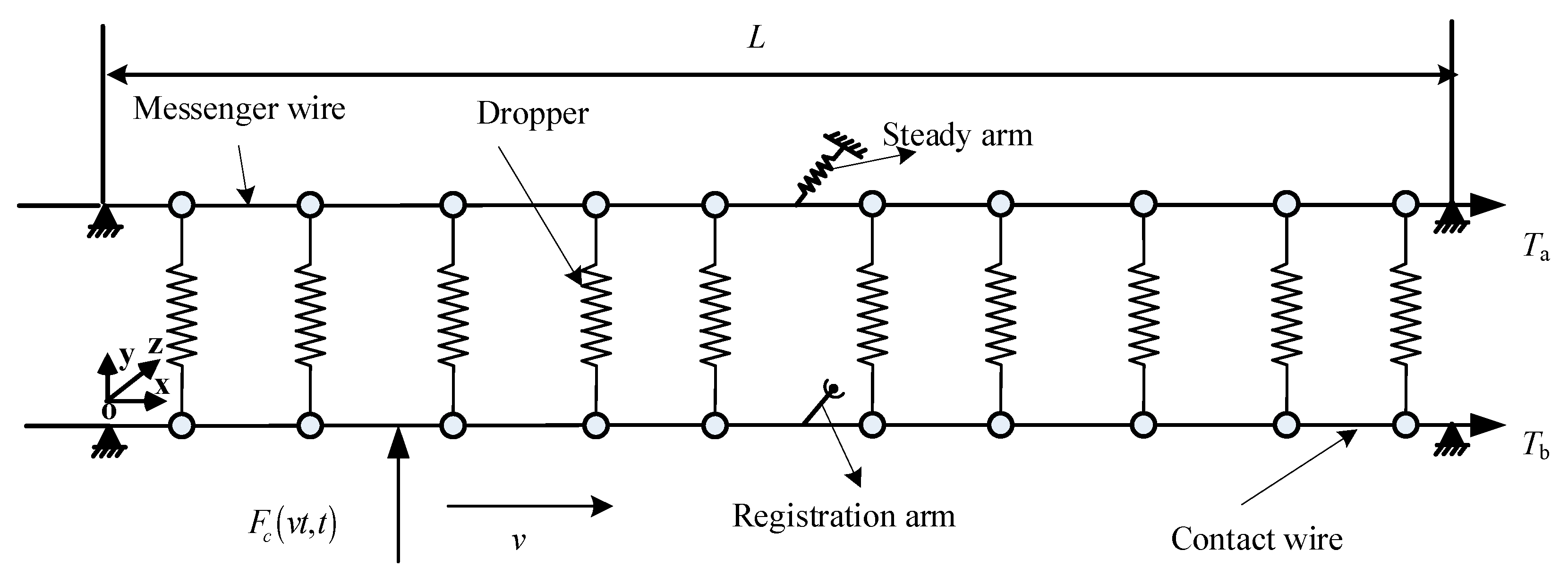
Figure 2.
Pantograph–catenary contact model.
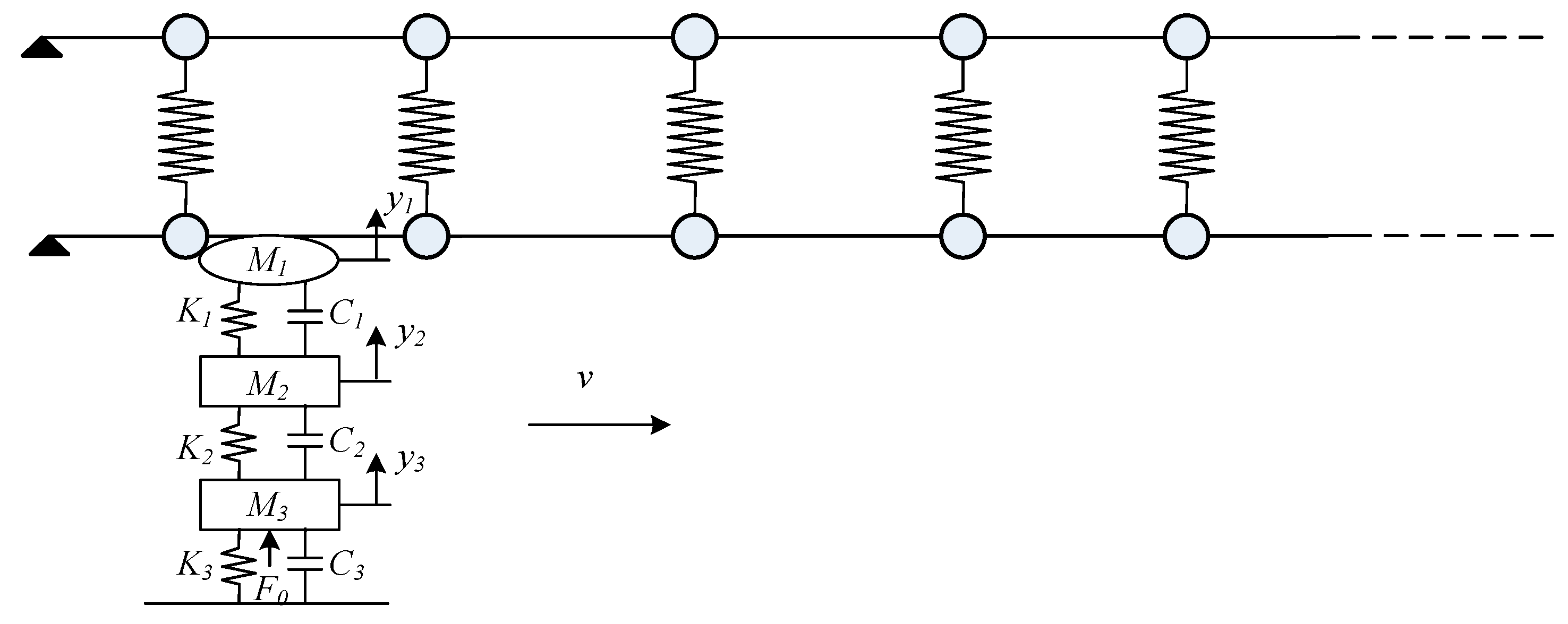
Figure 3.
Uplift and velocity of the pantograph head at contact points (from 38 m to 50 m). (a) Uplift of the pantograph head; (b) velocity of the pantograph head.
Figure 3.
Uplift and velocity of the pantograph head at contact points (from 38 m to 50 m). (a) Uplift of the pantograph head; (b) velocity of the pantograph head.
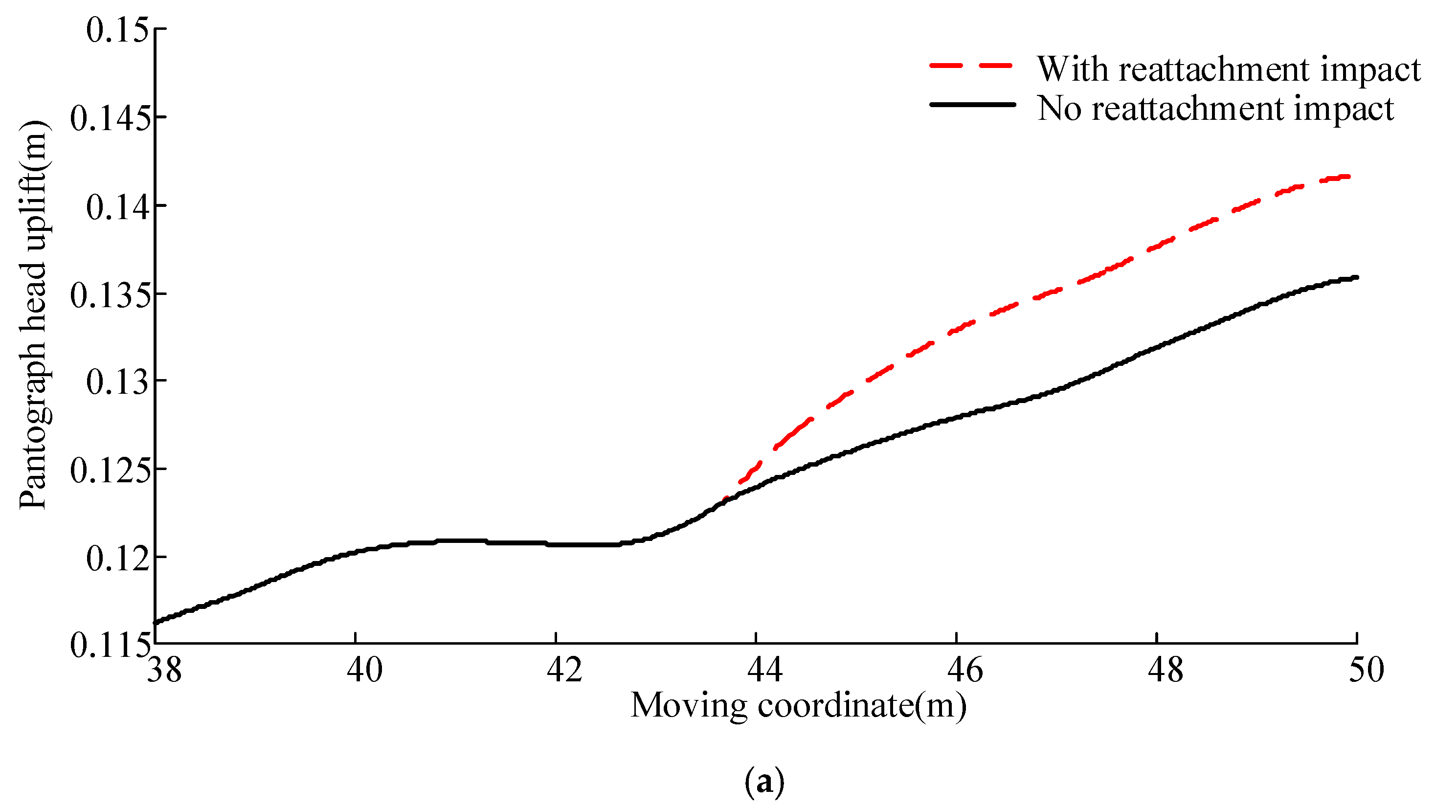
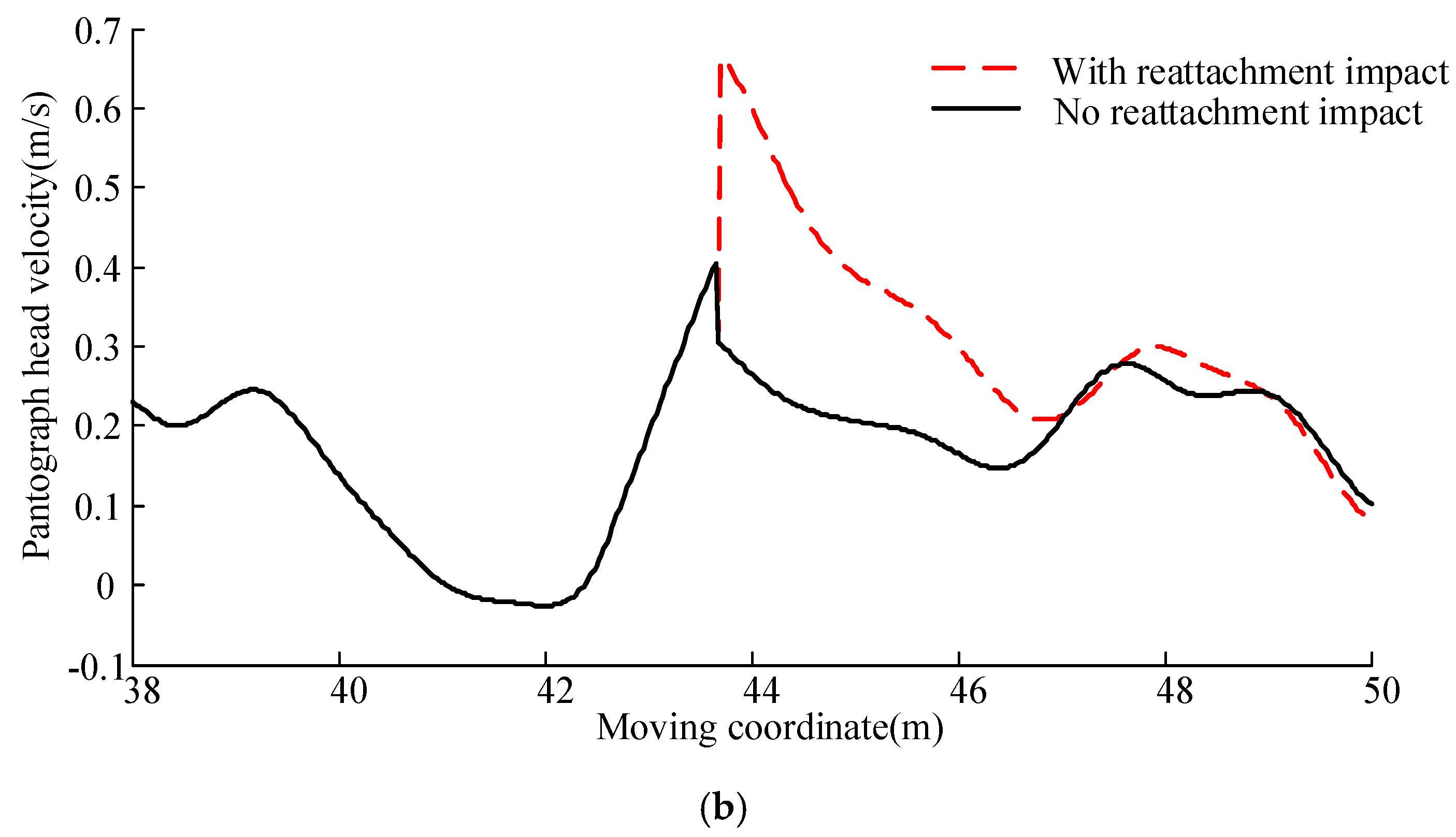
Figure 4.
Velocity of the contact wire at contact points (from 38 m to 50 m).
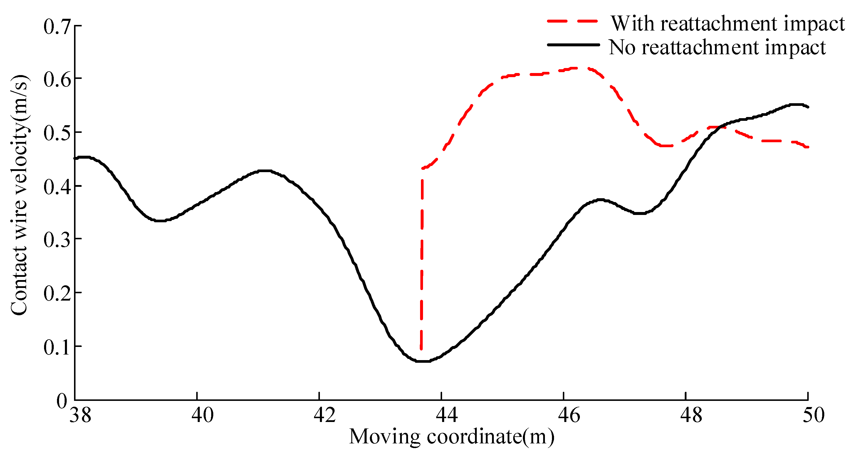
Figure 5.
Contact force of the pantograph–catenary (from 38 m to 50 m).
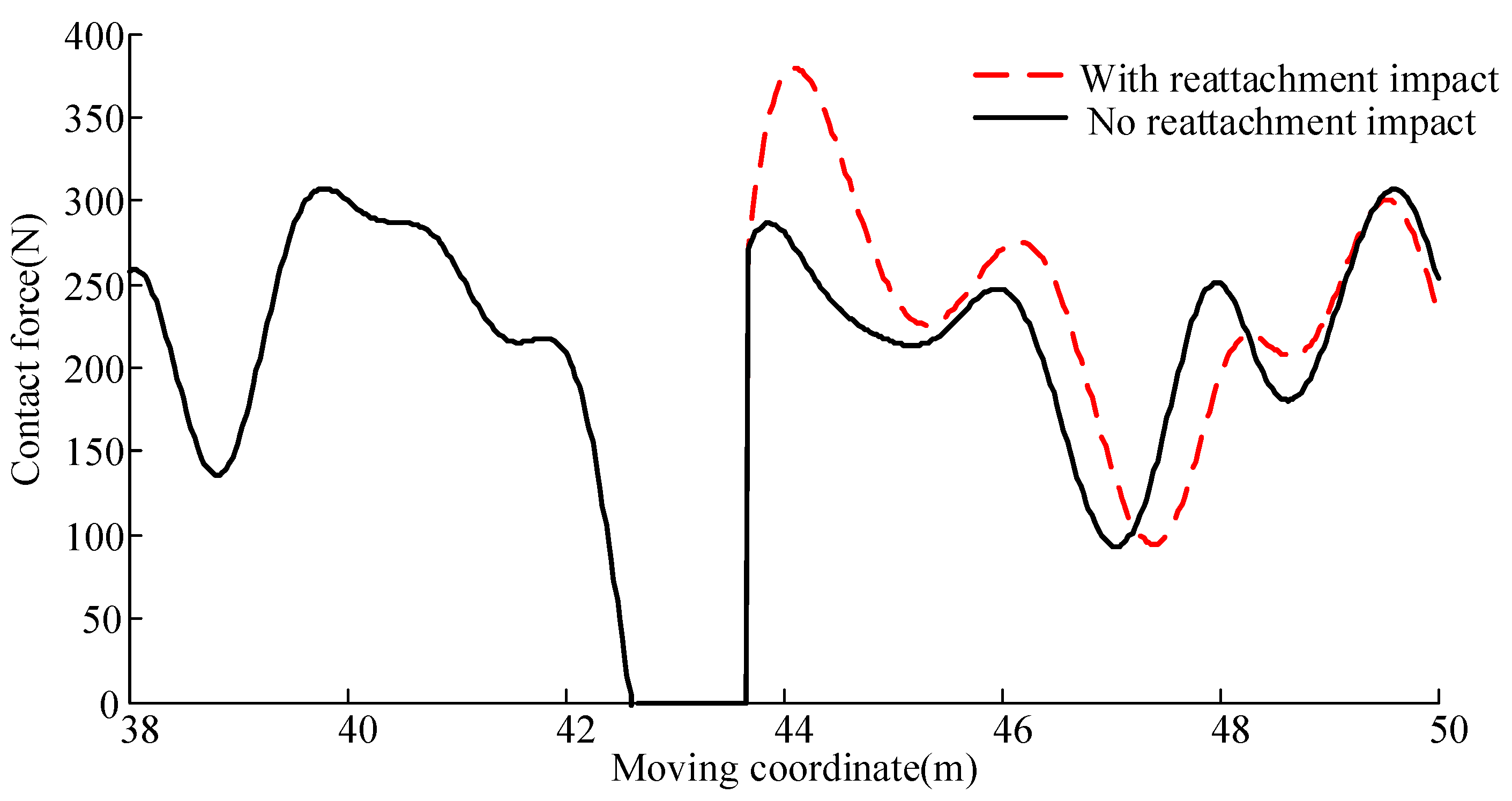
Figure 6.
Maximum contact force, contact force standard deviation and contact loss at different speeds. (a) Maximum contact force; (b) standard deviation; (c) contact loss.
Figure 6.
Maximum contact force, contact force standard deviation and contact loss at different speeds. (a) Maximum contact force; (b) standard deviation; (c) contact loss.
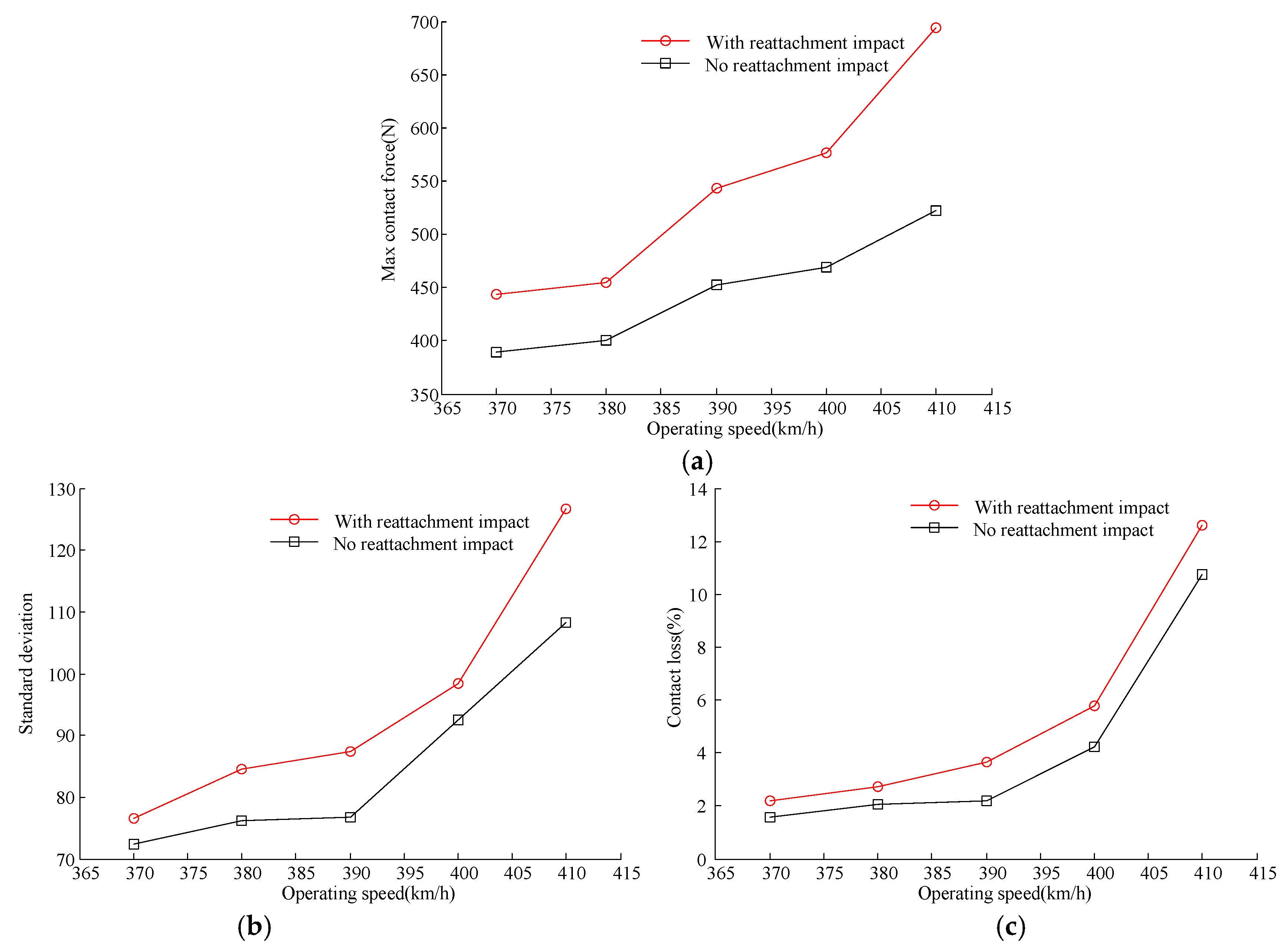
Figure 7.
Contact force with different M1 at 370 km/h.
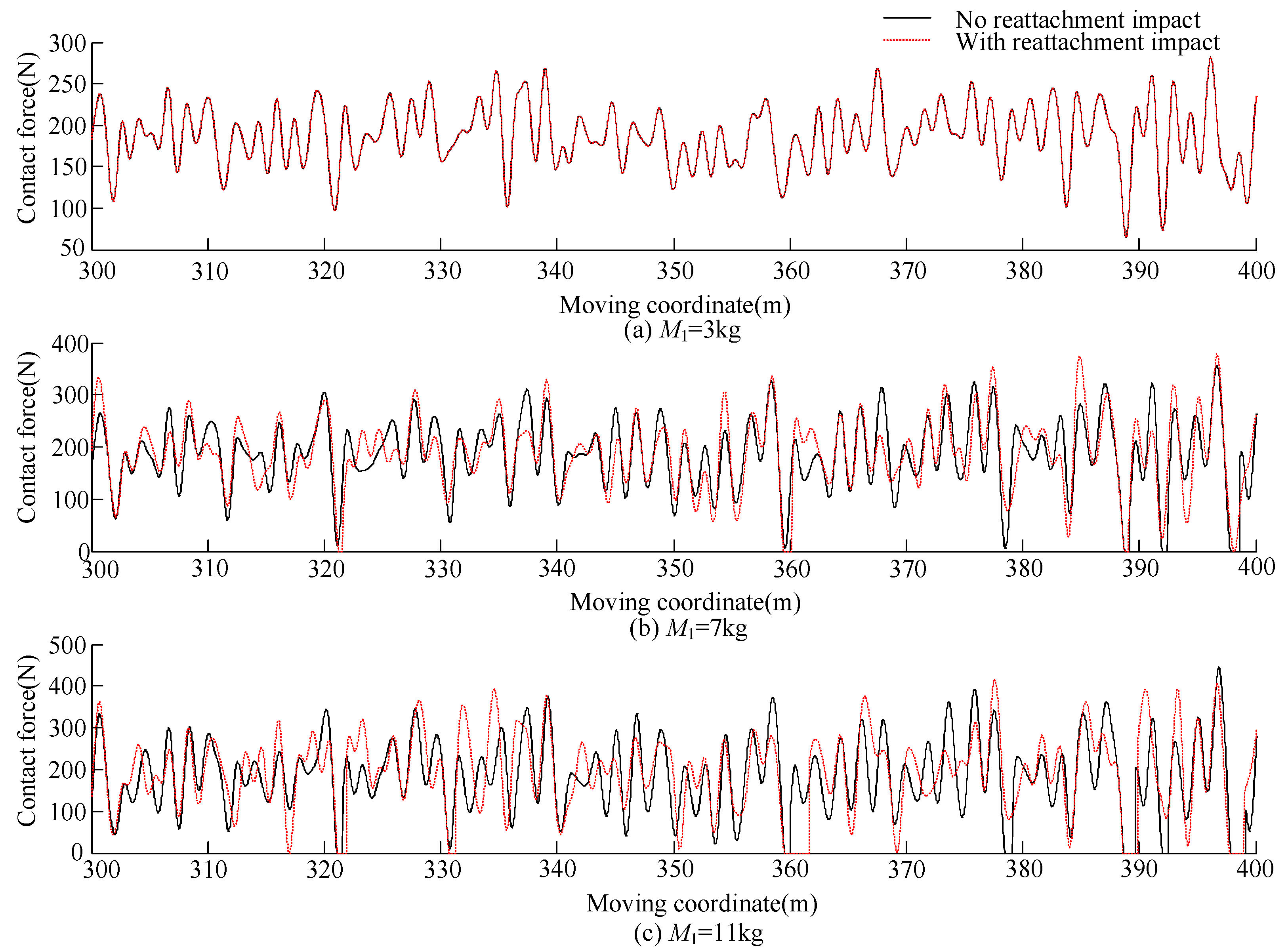
Figure 8.
Contact force with different M1 at 380 km/h.
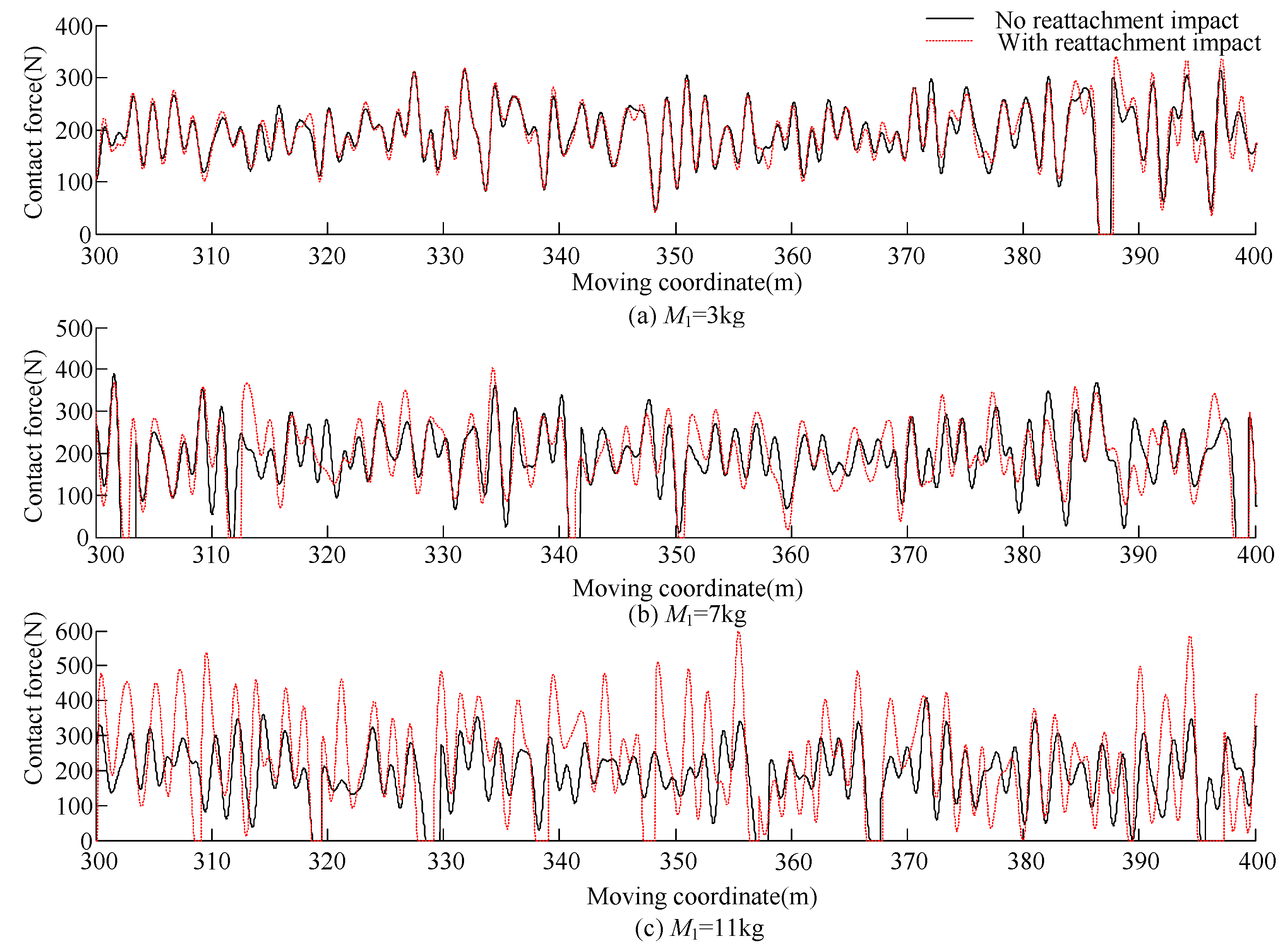
Figure 9.
Maximum contact force, contact force standard deviation and contact loss with different M1. (a) Max contact force; (b) standard deviation; (c) contact loss.
Figure 9.
Maximum contact force, contact force standard deviation and contact loss with different M1. (a) Max contact force; (b) standard deviation; (c) contact loss.
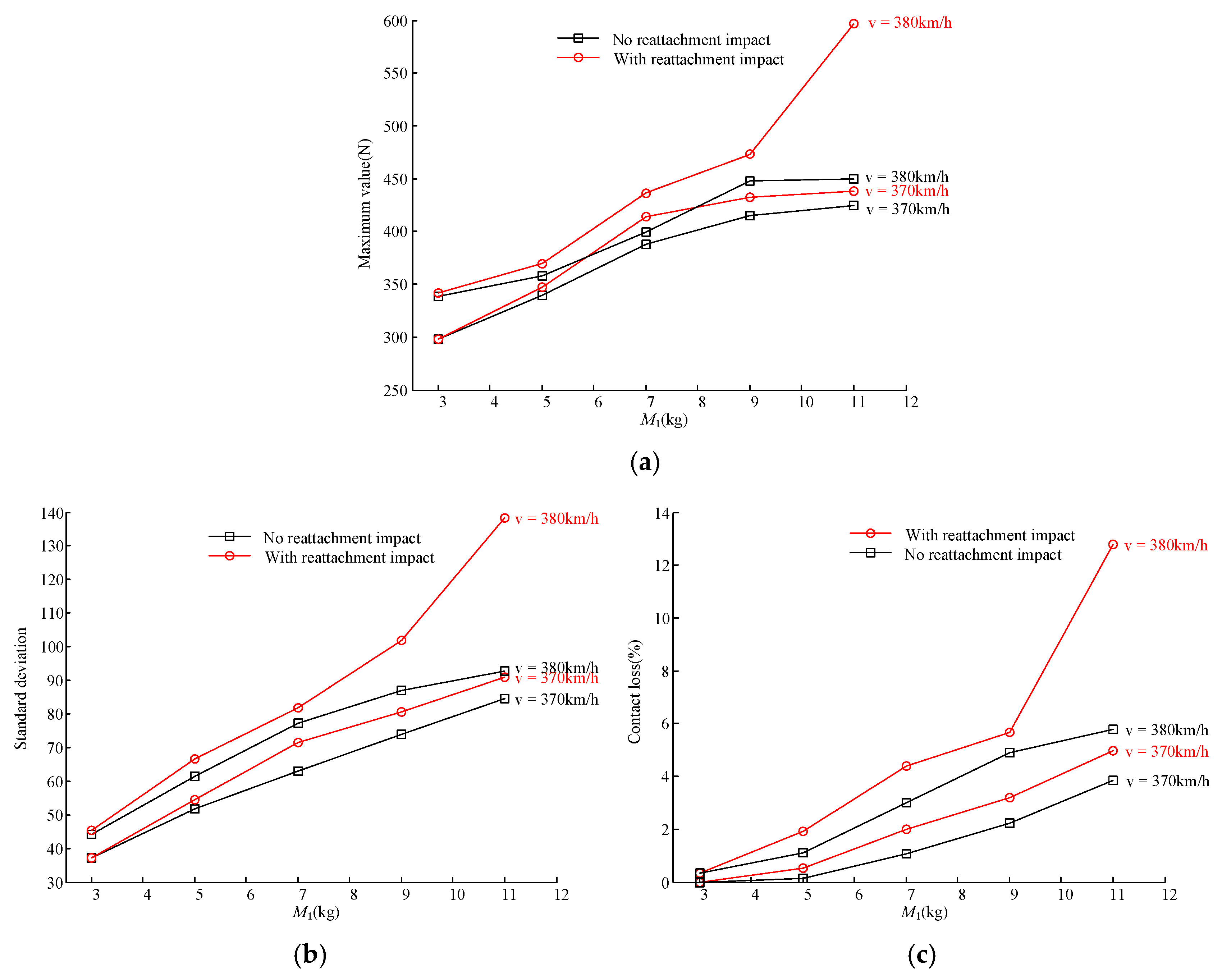
Figure 10.
Contact force with different K1 at 380 km/h.
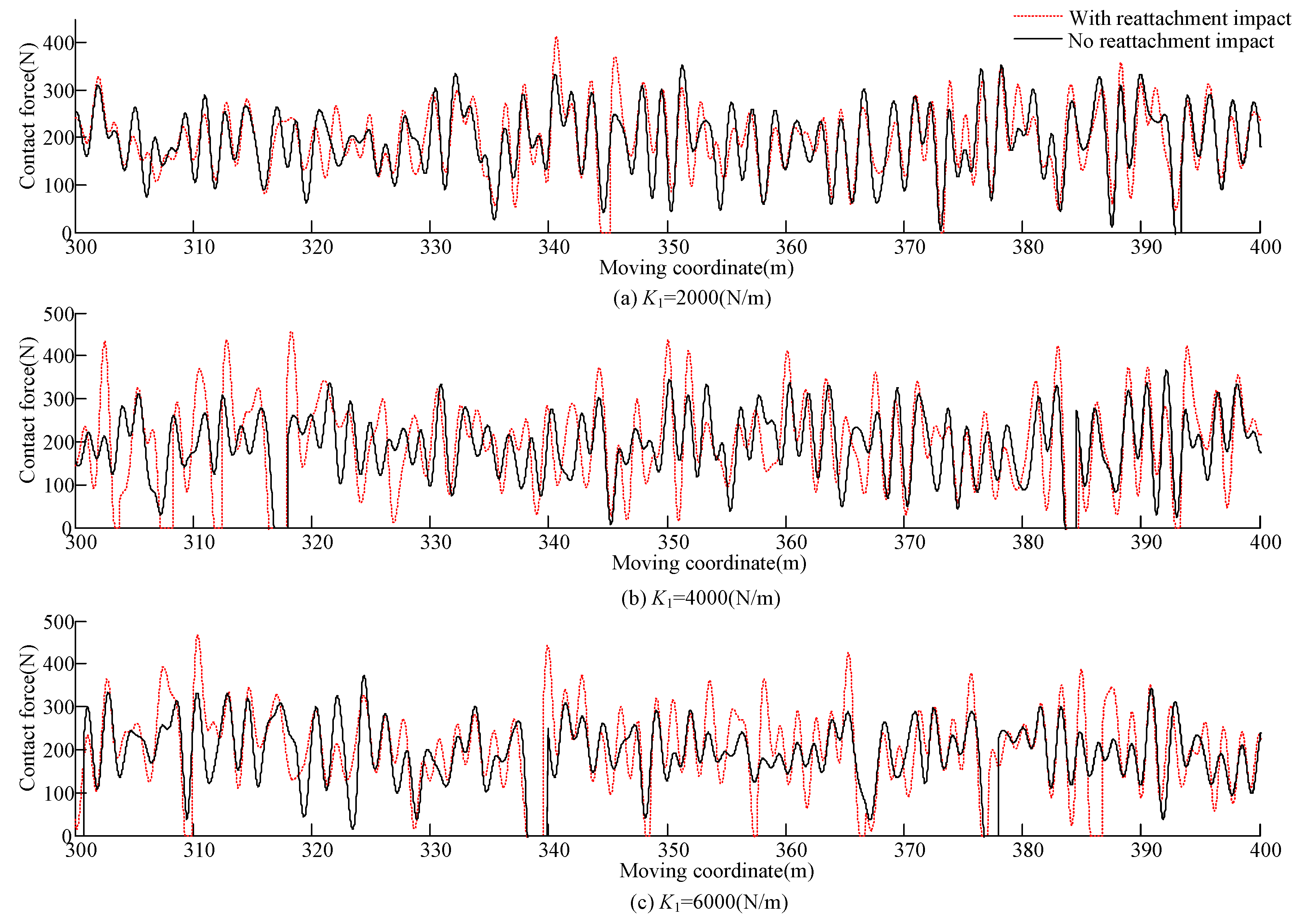
Figure 11.
Maximum contact force, contact force standard deviation and contact loss with different K1. (a) Max contact force; (b) standard deviation; (c) contact loss.
Figure 11.
Maximum contact force, contact force standard deviation and contact loss with different K1. (a) Max contact force; (b) standard deviation; (c) contact loss.

Table 1.
Simulation parameters of high-speed railway catenary.
| Item | Value | Item | Value |
|---|---|---|---|
| Span | 48 m | Interval of droppers | 5/9.5/9.5/9.5/9.5/5 m |
| Contact wire tension | 27 kN | Simulated length | 10 spans |
| Messenger wire tension | 21 kN | Messenger wire type | CuMg0.5 AC 120 |
| Number of droppers | 5 | Contact wire type | BZ II 120 |
| Dropper stiffness | 1 × 10⁵ N/m | Dropper mass | 0.4 kg |
| Messenger wire support stiffness | 1 × 10⁷ N/m | Steady arm mass | 1.125 kg |
Table 2.
Simulation parameters of pantograph.
| Item | 1 | 2 | 3 |
|---|---|---|---|
| M (kg) | 6 | 7.12 | 5.8 |
| C (Ns/m) | 0 | 0 | 70 |
| K (N/m) | 9430 | 14,100 | 0.1 |
| Maximum operating speed: 350 (km/h); F0 = 0.00097 × v2 + 70 (N) | |||
© 2020 by the authors. Licensee MDPI, Basel, Switzerland. This article is an open access article distributed under the terms and conditions of the Creative Commons Attribution (CC BY) license (http://creativecommons.org/licenses/by/4.0/).
Share and Cite
MDPI and ACS Style
Chu, W.; Song, Y. Study on Dynamic Interaction of Railway Pantograph–Catenary Including Reattachment Momentum Impact. Vibration 2020, 3, 18-33. https://doi.org/10.3390/vibration3010003
AMA Style
Chu W, Song Y. Study on Dynamic Interaction of Railway Pantograph–Catenary Including Reattachment Momentum Impact. Vibration. 2020; 3(1):18-33. https://doi.org/10.3390/vibration3010003
Chicago/Turabian StyleChu, Wenping, and Yang Song. 2020. "Study on Dynamic Interaction of Railway Pantograph–Catenary Including Reattachment Momentum Impact" Vibration 3, no. 1: 18-33. https://doi.org/10.3390/vibration3010003