Article

Dynamic Analysis and Design of a Novel Ring-Based Vibratory Energy Harvester

by
Ibrahim F. Gebrel
1,
Ligang Wang
2 and
Samuel F. Asokanthan
1,*
1
Department of Mechanical and Materials Engineering, The University of Western Ontario, London, ON N6A 5B9, Canada
2
Department of Mathematica, College of Science, Harbin Engineering University, Harbin 150001, Heilongjiang, China
*
Author to whom correspondence should be addressed.
Vibration 2019, 2(3), 271-284; https://doi.org/10.3390/vibration2030017
Submission received: 28 June 2019 / Revised: 28 August 2019 / Accepted: 30 August 2019 / Published: 3 September 2019

Abstract

:
This paper aims to focus on the design and analysis of a novel ring-based mono-stable energy-harvesting device that is considered as an alternative to the beam and tube models used thus far. The highly sensitive ring second flexural mode, when combined with the nonlinear external magnetic force, results in an ideal combination that yields increased frequency range, and can be considered as novel in the field of vibration-based energy harvesters. A mathematical model for the ring structure, as well as a model to generate nonlinear magnetic force that acts on the ring structure, is formulated. The discretized form of the governing equations is shown to represent a Duffing oscillator in the presence of an external magnetic field. The forms of the system potential energy, as well as the restoring force, are examined to ensure that the mono-stable behavior exists in the proposed model. Numerical predictions of time response, frequency response, phase diagram, and bifurcations map when the system is subjected to ambient harmonic excitation, have been performed for the purposes of gaining an insight into the dynamics and power generation of this new class of harvesters.

1. Introduction

The exploitation of nonlinear dynamic system phenomena in the design of vibration-based harvesters has recently received much attention. The nonlinearity is often brought to the system via external co-ordinate-dependent nonlinear force. The present study focusses on the interaction of nonlinear magnetic forces that act on a flexible ring structure. An investigation into the performance of such a novel design, namely the mono-stable ring structure with nonlinear magnetic force, has been demonstrated via numerical simulations.
The nonlinear energy harvesters have become an evolving alternative to the use of batteries within electrical sensing and instrumentation systems. Vibration energy can be converted to electric energy using the common transduction mechanisms based on piezoelectric [1,2], electrostatic forces [3], or electromagnetic forces [4]. Several studies have described the behavior of mono-stable and bi-stable type nonlinear vibration energy harvesters; however, few studies compared their performance relative to one another. Daqaq et al. [5] provided a basic electromechanical model of a beam that can be used to build a quantitative understanding of nonlinear vibration energy harvester and they found that output voltage depends on the magnitude of base acceleration and the shape of the potential well. In particular, Stanton et al. [6] showed how magnetic levitation could be used to extend device bandwidth through a hardening frequency response.
A mono-stable energy harvester tube-structure that utilizes magnetic force is proposed by Mann and Sims [7]. In this study, the effect of large amplitudes on a wide frequency range is investigated. Further, Mann and Owens [8] investigated nonlinear behavior of a bi-stable energy harvester considering a series of magnets that are positioned to design a bi-stable tube system. Experimental and theoretical investigations are performed to extend the frequency range via a potential well. In another study related to the tube structure, Liu et al. [9] investigated a single degree of freedom oscillator in a cylindrical tube vibration energy harvester. The primary purpose of their study was to establish a dimensionless performance analysis method of a nonlinear electromagnetic vibration energy harvester system and to detect the effects of the parameters and nonlinearity of the system on the harvester performance. Zheng et al. [10] and Ramlan et al. [11] investigated the stochastic and periodic excitation of a bi-stable beam structure harvester theoretically and experimentally. Results of this study indicate that using a periodic excitation is more useful than the stochastic excitation to increase the bandwidth. Masana and Daqaq [12] investigated the influence of the potential shape and the excitation level on the performance of mono-stable and bi-stable clamped-clamped flexible beam-based vibration energy harvester. The study concluded that when the harvester is subjected to a base acceleration of small amplitudes, the mono-stable harvester outperformed the bi-stable harvester with deeper potential shape, whereas at high amplitudes, the bi-stable harvester performed better. Abusoua and Daqaq [13] demonstrated via theoretical work that the effective nonlinearity associated with the resonant dynamics of a mono-stable asymmetric oscillator can be adjusted by injecting a hard high-frequency non-resonant excitation. In another study, Abusoua and Daqaq [14] demonstrated experimentally that vibration resonance phenomenon in bi-stable mechanical oscillators could help activate the inter-well dynamics of a bi-stable structure at lower amplitudes of the slow excitation. Shengxi et al. [15] proposed a novel nonlinear piezoelectric energy-harvesting model that consists of a linear piezoelectric energy harvester connected by linear springs to improve broadband energy harvesting based on a beam structure. Martínez-Ayuso et al. [16] performed an experimental study employing novel materials, such as the porous piezoelectric ceramics, in order to validate the applicability of homogenization theories and finite element approaches for energy harvesting applications. In their work, the beam is excited in a range of frequencies close to the first and second modal frequencies using base excitation. It may be noted that use of such materials can be considered as promising in the field of present and future vibration-based energy harvesters. Zhou and Zuo [17] demonstrated that nonlinear dynamic analysis of asymmetric tri-stable energy harvesters could be used for enhanced energy harvester for various conditions.
It is worth noting that most of the studies described above employed beam and tube structures to design harvesting systems. However, ring structure harvester is more promising due to inherent advantages such as high mode sensitivity and minimal sensitivity to temperature fluctuation when compared with other structures. To the best of the author’s knowledge, it appears that no study has been performed on employing a ring structure as a harvester. Hence, there is a need for extending the applications to other responsive structural systems such as the ring systems proposed in the present study.
A number of studies on the linear and nonlinear dynamic behavior of vibrating rings have been undertaken in the recent past. Evensen [18] performed one of the early studies on the nonlinear vibration of rings considering only the in-plane vibrations of a thin circular ring and derived nonlinear equations of motion. Evensen [19] later performed detailed studies on nonlinear flexural vibrations of rings considering two vibration modes. Further, the dynamic behavior of angular rate sensors that are subjected to external excitation was studied by Huang and Soedel [20] to evaluate the natural frequencies and mode shapes under ring rotation. Asokanthan and Cho [21], and Cho [22] developed mathematical models for rotating ring-based angular rate sensors for the purposes of investigating linear, nonlinear dynamic behavior and dynamic stability of angular rate sensors. The dynamic response behavior of rotating thin circular rings for use in vibratory angular rate sensors was investigated by Gebrel et al. [23] via numerical simulations, by employing the linearized model considering the second mode. In the same study, they developed a suitable theoretical model to generate nonlinear electromagnetic forces that are used for exciting the ring from two positions to obtain improved device sensitivity.
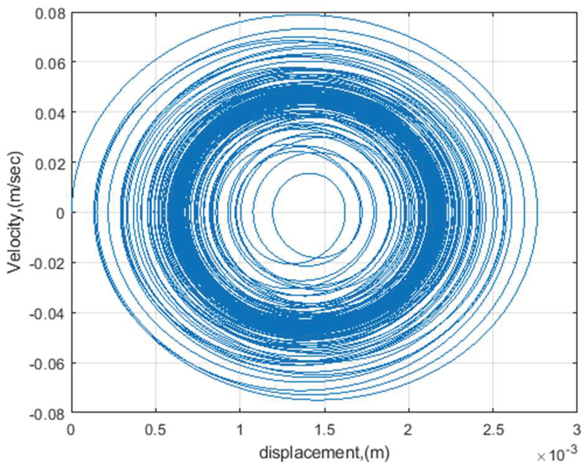
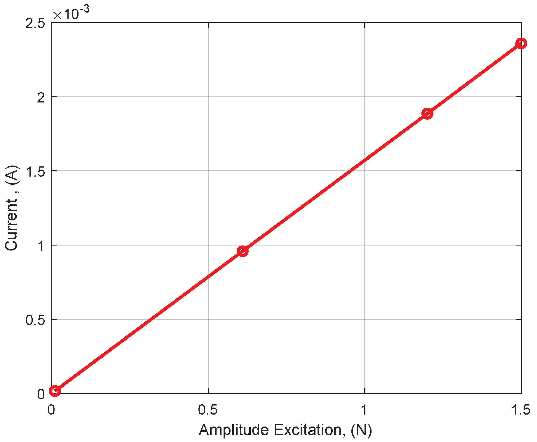
In the present study, a novel ring-based nonlinear energy harvester device is designed. Magnetic forces are employed to generate appropriate nonlinear systems that exhibit mono-stable behavior which can be utilized as harvester. A mathematical model that represents the dynamic behavior of the system is derived based on a vibratory ring assuming that the ring is completely symmetric. The equations of motion are simplified by ignoring the extensional vibrations, since only the second resonant flexural mode is excited in this class of applications. An external magnetic field is employed in a repulsive configuration to assist the harvesting of energy from the vibratory flexural motion of the ring when subjected to ambient sources. The dynamic behavior of ring harvester has been investigated via numerical simulations to examine the efficacy of this class of harvesters. Time responses, a phase diagram, and a bifurcation map are investigated under harmonic excitation that represents ambient energy sources. Frequency response in the form of bifurcation maps is utilized to optimize the conditions for harvester operation. It is worth noting that the current proposed ring configuration has multiple magnet positions to attain the harvesting function compared to the beam, which has limited positions for the magnets. Further, the proposed ring harvester can also benefit from multiple driving directions for a single ring, which is not feasible with a single beam structure.

2. Governing Equations

The governing equations of flexural motion of vibrating thin circular rings are developed for the purpose of investigating the dynamic behavior of ring harvester. In the present model, simplified equations of motion have been obtained by assuming the circumferential strain in mid-surface is zero and isotropic, as well as homogenous material properties. In addition, Euler–Bernoulli assumptions—that the plane sections remain plane after deformation and normal to the neutral surfaces, and that the transverse shear deformation effect is ignored as presented by Asokanthan and Cho [21]—are adopted in this model. Galerkin’s procedure is used to discretize the equations for numerical response predictions. The viscous damping of the ring harvester is included in the final approximated equations of motion.
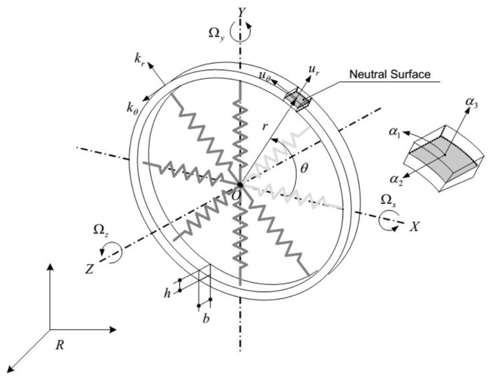
Figure 1 illustrates the geometry and parameters used in the present study. The ring is considered to be supported internally with eight springs with the stiffness components k r and k θ , which represent the radial, and circumferential components, respectively, while u r and u θ represent the transverse and circumferential displacements, respectively. The support springs are considered to possess significantly low stiffness and hence assumed not to have significant effects on the ring. A body-fixed frame   X , Y , Z has been used for representing the angular motion of the ring with respect to the inertial frame R , and the locations of the neutral surface elements in the rotational co-ordinates can be defined by introducing curvilinear surface co-ordinates α 1 , α 2 , and α 3 .
The general equations of motion that govern the transverse and circumferential motions can be derived via Hamilton’s principle, as described in the papers by Asokanthan and Cho [21] and Huang and Soedel [20]. For this purpose, expressions for various energy terms are developed. The kinetic energy of the rotating ring is generated in the absence of translational and rotational rigid body motion of the ring. Under this condition, using the equations developed in Cho [22] in the presence of external nonlinear magnetic excitation force f N m   ( A n , B n , θ i ) as well as an ambient force f e   , the governing equation for the vibrating ring with linear in-extensional condition in the radial direction takes the form:
E A b r 2 ( u θ + u r ) E I b r 4 ( u θ u r ) + k r u r + ρ h u ¨ r =   f N m   ( A n , B n , θ i ) + f e   ,
where the time derivatives are indicated by (   ) ˙ , while the spatial derivatives are indicated by   (   ) . In Equation (1), E is Young’s modulus, I denotes the area moment of inertia for the ring cross-section , ρ represents mass density, E I represents flexural rigidity, A is the cross-sectional area of ring, b denotes axial thickness of ring, h represents radial thickness, and r is the mean radius of the ring. Oscillatory external nonlinear magnetic force magnitude is represented by   f N m   ( A n , B n , θ i ) , while the area moment of inertia of the ring cross-section about its neutral axis is expressed as I = b h 3 / 12 .
Assuming mode shapes for the ring second flexural modes, the partial differential Equation (1) is reduced to linear ordinary differential equations by applying Galerkin’s procedure. Due to the periodic nature of solutions and choice of deflection modes, the most general radial and circumferential (extensional) displacements compatible with the continuity requirements can be assumed as follows [18]:
u r = [ A n ( t ) cos n θ + B n ( t ) sin n θ ]
u θ = 1 n [ A n ( t ) sin n θ + B n ( t ) cos n θ ]
where A n and B n denote time-dependent generalized co-ordinates, while n denotes the number of modes. Evensen [18] has performed a detailed investigation of the dynamics of this class of structures. Each A n and B n can, in turn, be expanded as a Fourier series in time; thus, it is possible to represent virtually any radial or circumferential deflection of interest here in the Equations (2) and (3). The functions cos n θ and sin n θ are the linear vibration modes of the ring; and since only flexural motions are considered, Equations (2) and (3), in the present study, are restricted to n = 2 . In order to apply Galerkin’s procedure, Equations (2) and (3) are substituted for u r in Equation (1) and the resulting expression is then multiplied by weighting function associated with A n ( t ) and integrated with respect to θ from 0 to 2 π . This procedure yields an ordinary differential equation involving primarily A n ( t ) . When an equation for B n ( t ) is obtained in a similar fashion, both equations are coupled in the linear terms. The weighting functions used in this procedure are:
u r A n = cos ( n θ ) ,
and
u r B n = sin ( n θ ) ,
to obtain the equations for the co-ordinates A n ( t ) and B n ( t ) , respectively.
The equations of motion that govern linear dynamic behavior employing the second mode with nonlinear magnetic force, as well as harmonic ambient excitation, are derived employing Equations (1) through (4a) and (4b) as
ρ h π A n ¨ + 2 ζ ω 0 A n ˙ + [ E I b r 4 ( n 2 1 ) n 2 + k r ] π A n = f N m 1   ( A n , B n , θ i ) + f e  
ρ h π B n ¨ + 2 ζ ω 0 B n ˙ + [ E I b r 4 ( n 2 1 ) n 2 + k r ] π B n =   f N m 2   ( A n , B n , θ i ) + f e  
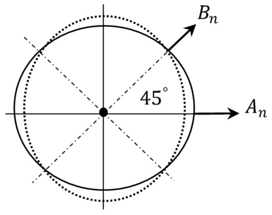
In Equations (5) and (6), the co-ordinate A n can be considered to represent the primary excitation or the driving co-ordinate of the ring, while the co-ordinate B n can be used as a secondary driving co-ordinate. The primary and secondary directions are shown in Figure 2. The parameter ζ represents the mechanical damping ratio, and ω 0 represents natural frequency.
In the present study, only the second flexural modes are considered, hence, the number of nodal diameter (or mode number)   n in the equations of motion, is taken to be 2. In order to represent the external forces in the ring, nonlinear magnetic forces f N m 1 , 2   ( A n , B n , θ i ) are considered as an external force. The harmonic excitation to be received from the ambient vibratory energy sources is represented by f e   = f c o s ( ω t ) , where ω is the excitation frequency, and f is the excitation amplitude. The positions of magnets on the system correspond to θ i , i = 1 ,   2 , 3, 4.
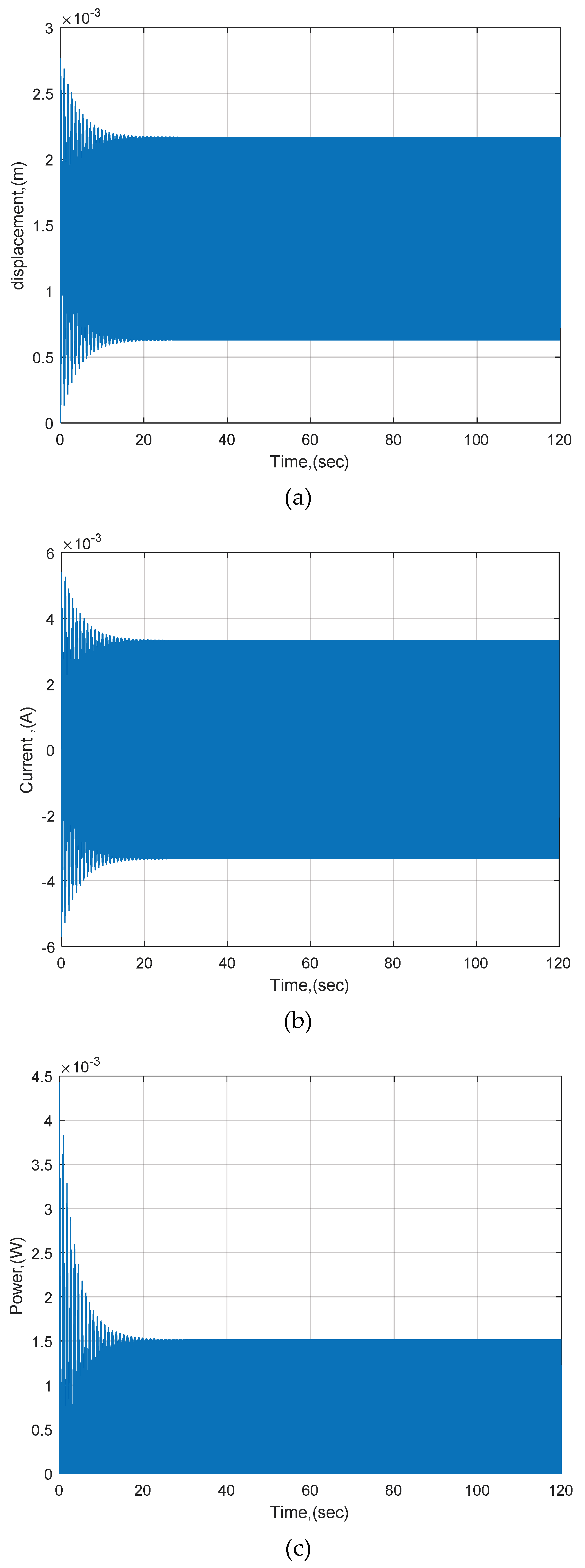
The present study focuses on a mono-stable energy-harvesting-based ring structure using the primary co-ordinate and, hence, Equation (5) must be employed together with an equation that represents the output power generation. The governing equations for the energy generator directly powering a resistive load are given by
ρ h π A n ¨ + 2 ζ ω 0 A n ˙ + [ E I b r 4 ( n 2 1 ) n 2 + k r ] π A n γ 1 I _ = f N m 1   ( A n , B n , θ i ) + f e  
L I _ ˙ + R ˇ   I _ + γ 1 A n ˙ = 0   ,
where A n is the displacement of the ring in the transverse directions, I _ is the electrical current, is the inductance of the coil, and R ˇ represents the load resistance, while γ 1 denotes the transducer constant (see, e.g., Ref. [8]), which can be derived from Faraday’s law of inductions, that couples the mechanical and electrical systems.

3. Development of Nonlinear Magnetic Forces for the Ring-Based Harvester Model

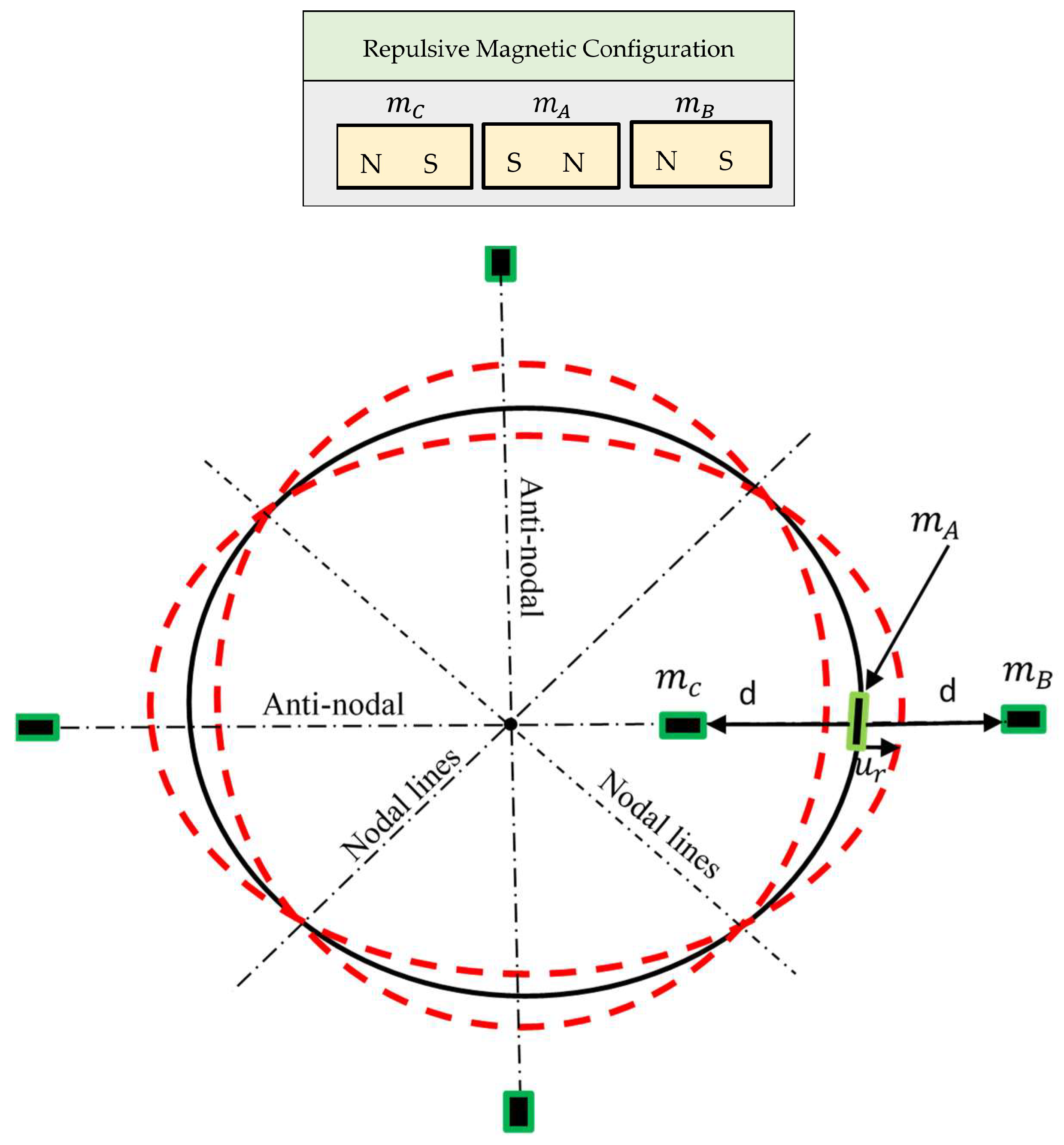
A schematic diagram of the magnetic configurations system is shown in Figure 3. Many arrangements of the magnets have been examined so that an efficient ring harvester system utilizing the second mode of a ring structure can be realized in practice. In order to represent the oscillatory nonlinear magnetic force that acts on the ring structure, a novel design and analysis of a theoretical model formulation is employed. This analysis is restricted to mono-stable configurations. For the purposes of accounting the interactions between the magnets ( m A , m B , and   m C ) , the potential energy and force expressions are derived from a dipole model by the law of Biot and Savart (see, e.g., Ref. [24]). The important features of the force characteristics are introduced via force expressions for an interacting magnetic dipole for one side of the system, as shown in Figure 3. The magnetic flux density is defined by
B B A   = μ 0 4 π m B .     r B A | r B A | 3 ,
where μ 0 = 4 π × 10 7 H / m denotes the magnetic permeability of free space,   is vector gradient, m B = M B V B   e r ,     M B is the magnetization, and V B represents the volume of the source magnet, and | r B A | = ( d u r ) e r is the distance between magnets m B and m A . The potential energy of the magnet m A in the field generated by the magnet m B is
U m = m A .   B B A ,
where m A = M A V A , M A is the magnetization, V A represents the volume of the source magnet, and U m is the potential energy, (see, e.g., Ref. [24]). The expression for the interaction force between the magnets can then be obtained by taking the gradient of Equation (10). As shown in Figure 3, magnets B and C are identical and their distance from magnet A is designated as   d . The expression for the total potential energy associated with magnets A , B and C can be derived employing Equations (9) and (10) considering the flux density between the magnets:
U m = μ 0 2 π M A M B V A V B [ 1 ( d u r ) 3 + 1 ( d + u r ) 3 ] ,
where d 
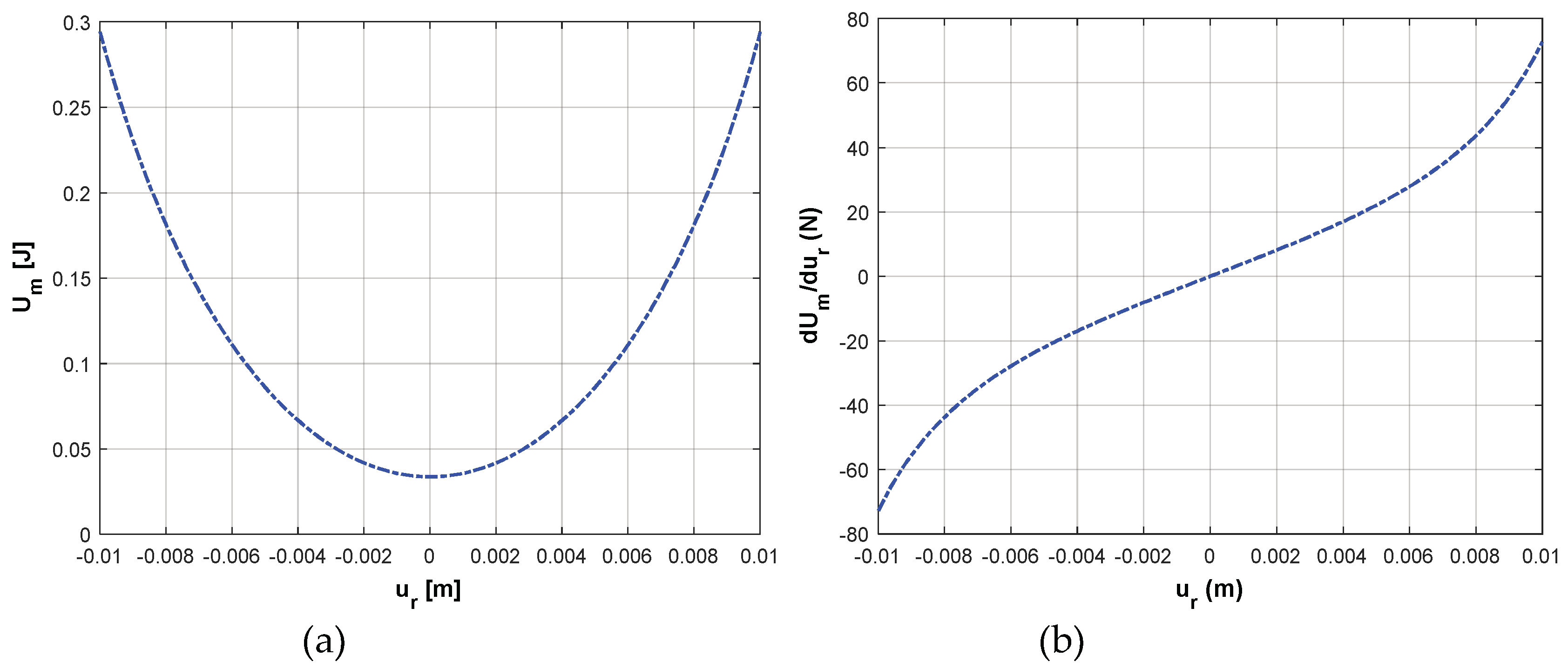
represents the distance between magnets. An expression for the magnetic force between two magnets can now be obtained by differentiating the potential energy expression Equation (11) with respect to r ; the force expression takes the form:
f N m = μ 0 2 π M A M B V A V B [ 3 ( d u r ) 4 3 ( d + u r ) 4 ]
In order to simplify the force expression, Taylor expansion is applied to Equation (12) to yield the following equation:
f N m = 3 * μ 0 2 π M A M B V A V B [ ( 8 * u r ) d 5 + ( 40 * u r 3 ) d 7 + ( 112 * u r 5 ) d 9 + O ( u r 7 ) ] .
When terms of up to the third order are retained in Equation (13), the f N m , which is a nonlinear function of u r , can be thought of as generating the nonlinear stiffness terms that govern the mechanics of the ring structure. The first term in the brackets is the linear part of the force, while the remaining terms represent nonlinear parts. The expression given in Equation (12) may be extended to handle multiple magnets that may be arranged around the periphery of the ring. In order to extend the magnetic dipole configurations to multiple sets, a novel example with four sets separated by 90 degrees is developed, as shown in Figure 3. In this case, the expression for the nonlinear magnetic force which affects the system from four positions when i = 1 , 2 , 3 , 4 is derived. The expression for the nonlinear magnetic force that affects the system at the four positions, employing Equations (2) and (12) developed for single magnet system, is derived as
f N m 1 ( A n , B n , θ i ) = μ 0 2 π M A M B V A V B i = 1 4 cos ( n θ i ) [ 3 ( d A n cos ( n θ i ) B n sin ( n θ i ) ) 4   3 ( d + A n cos ( n θ i ) + B n sin ( n θ i ) ) 4 ]
where θ i represents the position of magnets on the system namely, i = 1, 2, 3, 4. The magnetic force component presented in Equation (14) forms the basis of harvester dynamics. This force introduces not only a change in the linear stiffness but also a change in the nonlinear stiffness component.

4. Natural Frequency of Ring Structure

The primary purpose of the present paper is to understand the mechanics of a ring-based mono-stable harvester, with an ultimate intent of further understanding the effects of nonlinear magnetic/ambient forces that act on a ring-based harvester. This paper also serves as an aid for the experimental system design. The priority for the design scaling was given to using materials that lend themselves to easy fabrication and an easily identifiable second flexural mode with a relatively low natural frequency.
It may be noted that the mechanical model conforms to the experimental system developed as presented in the research performed by Cho [22]. Figure 4 illustrates the experimental arrangement developed for studying the natural frequency of the ring system in the present study and will be used further for studying the dynamic behavior of ring harvesters in forthcoming studies. This arrangement consists of a circular cylindrical structure where all sensors and actuators and a sensor driver are setup on a test base which is attached to a precision Single-Axis rate Table. The cylindrical structure made of blue-tempered spring steel is able to be excited via non-contact electromagnetic excitation. The ring structure is attached on the center of the test base, while two electromagnets are arranged on an anti-nodal line to excite the free cylinder end. Two Eddy-current displacement sensors are arranged on the other anti-nodal line and one of the nodal lines. The behavior of the ring can be observed by examining the free end of the cylinder, considering it as a ring attached on a cylinder-end. Hence, all of the sensors and exciters are arranged along the free end circumference of the cylinder. It can be noted there is no physical contact present between the free cylinder-end and the exciter.
For the chosen material and dimensional properties, the natural frequencies of the system have been validated experimentally. The system natural frequency associated with the second flexural mode has been computed mathematically to be   61.34   r a d / s e c and experimentally to be   58.24   r a d / s e c . The discrepancy may be attributed to the uncertainty in system parameters, as well as inherent structural mass mismatch. It may be noted that, for simulation purposes, the excitation frequency was selected close to the theoretical natural frequency.

5. Results and Discussion

As discussed above, Equations (7) and (8) form the foundation for the mono-stable energy harvesting analysis based on the ring structure. To achieve the objectives of the present study, a dynamic response analysis of the system subjected to nonlinear magnetic force as well as harmonic force is examined via the numerical procedure. The analysis is based on the mathematical model derived in the previous sections. Prior to performing the dynamic response analysis, natural frequency has been determined for the linear model. The potential energy of the system is investigated to ensure that the mono-stable behavior exists in the proposed model. Restoring force, which is the derivative of the potential energy with respect to the displacement, is also examined for the purpose of identifying the hardening behavior of the system. Time responses, phase diagram, and bifurcation maps are generated under harmonic excitation to determine the output system’s characteristics. In addition, to characterize the behavior due to varying frequencies of the input excitation, a frequency sweep analysis is performed.

5.1. Potential Energy and Restoring Force

Figure 5a shows the function of the total potential energy of the mono-stable energy harvester. It can be seen that the harvester has one potential well. In order to illustrate the applicability of the analytical results, typical parameters associated with a macro ring-type harvester are considered, as shown in Table 1. Based on an approximate form of Equation (13) by retaining terms of up to order 3, a practical physical system has been realized when a magnet m A of small mass and two fixed magnets m B , m C are used. These magnets, when arranged in a repulsive configuration as depicted in Figure 3, leads to a “hardening” system where the force plot takes the form as shown in Figure 5b, while the potential energy takes the form as shown in Figure 5a, which shows a mono-stable configuration with one stable equilibrium point. Further, it can be shown that dipole arrangements with multiple sets around the ring at anti-nodal lines also lead to mono-stable configurations. This mono-sable configuration can be utilized to harvest energy.

5.2. Time and Frequency Responses

For the purposes of predicting the response characteristics of the harvester, Equations (7) and (8) have been solved numerically. The system parameters are chosen based on the available experimental ring-structure setup that has been used in Cho [22] and which is also under development for future experimental validation of the present study. For the electrical subsystem, the number of turns of the coil,   N c o i l is taken to be 3000 turns. The coil inner radius r c o i l has a value of 0.025   m while the coil height,   l c o i l is 0.0608   m . The inductance of the coil is estimated from L μ 0 ( N c o i l 2 π r c o i l 2 / l c o i l ) and it takes the value of 0.3652   H (see, e.g., Ref. [25]). The system natural frequency,   ω 0 has been determined and it has a value of   60   r a d / s e c . The system parameters   ζ = 0.01 and   γ 1 = 10   V s / m . The load resistance R can be derived from inductive reactance formula R = 2 π ω 0 L and it takes the value of 137   o h m .
For the system parameters used in the present study, the system natural frequency associated with the second flexural mode has been computed mathematically to be   61.34   r a d / s e c and experimentally to be   58.24   r a d / s e c . Figure 6 illustrates the output power, generated current, and displacement time responses for the system at an excitation frequency of   60   r a d / s e c chosen close to the system natural frequency. An initial displacement in driving direction of amplitude of 5 × 10 3   m and initial zero velocity are imposed on the system. The resulting response has a periodic oscillatory behavior. The steady state value of the displacement is 0.002167   m , while steady state values of the generated current and power are 3.326   m A and 1.515   m W , respectively. The obtained output power from the current ring design is comparable to the bi-stable tube or bi-stable beam harvesters presented in previous studies (see, e.g., [5,8]). For similar system parameters and initial conditions, if the excitation amplitude is increased, the transient response is followed by large amplitude periodic oscillation on high energy with a substantially improved power response, as shown in Figure 6.
Figure 7 shows the velocity vs. displacement trajectories for the present magnetic configurations. As can be seen from the periodic orbits appearing in this figure, the steady state vibration amplitude can be clearly seen to be stable. However, the presence of nonlinearities seems not to be evident from the plot, hence a predominantly linear behavior is displayed by periodic orbits for the mono-stable harvester system.
Simulations have been performed for varying amplitudes of excitation force in the range ( f = 0.01 1.5   N ) , and the corresponding current output has been depicted in Figure 8. An increase in the excitation force magnitude results in an increase in generated current from the harvester.
For the purposes of estimating the performance of the ring harvester, a frequency sweep was performed, numerically employing the displacement, current and power data considering the Poincare’ data sets. For this purpose, the bifurcation behavior with a linear slowly varying frequency spanning the range from 0 120   r a d / s e c has been computed and shown in the form of a bifurcation map in Figure 9. Variation of the frequency was executed such that the resulting high amplitudes, close to the natural frequency as well as the frequency range, can be extracted from the steady-state behavior of the system. The largest level of excitation used in the present study detected a significant broadening of the peak responses in the range 50 70 r a d / s e c , as shown in Figure 9. This may be attributed to the magnetic actuation provided in the present harvesting system. Further, a Power–frequency bifurcation map was generated in the absence of magnetic actuation, as shown in Figure 10. The comparison to the case with magnetic excitation depicted in Figure 9c reveals that, although higher peak values of power close to the natural frequency can be obtained in this case, this is at the expense of a significant reduction in the range of frequencies. It may be observed that the range is reduced to approximately 60 65 r a d / s e c from   50 70 r a d / s e c . The increased frequency response achievable with the use of magnetic actuation is envisaged to improved generation of power in the presence of more realistic band-limited random ambient excitation.

6. Conclusions

In the present study, the dynamic behavior of the ring harvester has been investigated via numerical simulations. Equations of motion that govern the dynamic behavior of a macro-scale ring harvester employing the second mode with a nonlinear magnetic force in the presence of harmonic ambient forces are derived. For this purpose, a novel model that generates a nonlinear magnetic force which affects the system at four angular positions is formulated. An improvement in the system output has been demonstrated by increasing the excitation amplitude. This paper illustrates that this enhanced bandwidth is dependent on the level of input external excitation, the size of the magnet and the shape of the potential function. The potential energy and restoring force have been examined to ensure that the mono-stable behavior exists in the proposed model. Results on the dynamic response obtained via time response, phase portraits, frequency response, and a bifurcation map are envisaged to provide physical insight into underlying mechanics. Further, the power predictions in the form of bifurcation maps may be utilized to achieve design improvements of ring-based harvesters, as well as provide aid for ongoing experimental research.

Author Contributions

I.F.G., L.W. and S.F.A. formulated and designed the system model; I.F.G. performed the numerical Simulations; I.F.G. and S.F.A. analyzed the results and wrote the manuscript.

Funding

This research was funded partially by National Science and Engineering Research Council (NSERC) of Canada discovery grant, grant #RGPIN/250432 and scholarship awarded to the first author by Libyan-North American scholarship program.

Acknowledgments

Natural Science and Engineering Research Council (NSERC) of Canada discovery grant and the Libyan-North American Scholarship program.

Conflicts of Interest

The authors declare no conflict of interest. The funding sponsors had no role in the design of the study; in the collection, analyses, or interpretation of data; in the writing of the manuscript, and in the decision to publish the results.

References

  1. Erturk, A.; Inman, D. Broadband piezoelectric power generation on high-energy orbits of the bistable Duffing oscillator with electromechanical coupling. J. Sound Vib. 2011, 330, 2339–2353. [Google Scholar] [CrossRef]
  2. Kim, S.; Towfeeq, I.; Dong, Y.; Gorman, S.; Rao, A.M.; Koley, G. P(VDF-TrFE) Film on PDMS Substrate for Energy Harvesting Applications. Appl. Sci. 2018, 8, 213. [Google Scholar] [CrossRef]
  3. Saghir, S.; Bellaredj, M.L.; Ramini, A.; Younis, M.I. Initially curved microplates under electrostatic actuation: Theory and experiment. J. Micromech. Microeng. 2016, 26, 95004. [Google Scholar] [CrossRef]
  4. Beeby, S.P.; Torah, R.N.; Tudor, M.J.; Glynne-Jones, P.; O’Donnell, T.; Saha, C.R.; Roy, S.; Beeby, S.; Saha, C. A micro electromagnetic generator for vibration energy harvesting. J. Micromech. Microeng. 2007, 17, 1257–1265. [Google Scholar] [CrossRef]
  5. Daqaq, M.F.; Masana, R.; Erturk, A.; Quinn, D.D. On the Role of Nonlinearities in Vibratory Energy Harvesting: A Critical Review and Discussion. Appl. Mech. Rev. 2014, 66, 040801. [Google Scholar] [CrossRef]
  6. Stanton, S.C.; McGehee, C.C.; Mann, B.P. Reversible hysteresis for broadband magnetopiezoelastic energy harvesting. Appl. Phys. Lett. 2009, 95, 174103. [Google Scholar] [CrossRef]
  7. Mann, B.; Sims, N. Energy harvesting from the nonlinear oscillations of magnetic levitation. J. Sound Vib. 2009, 319, 515–530. [Google Scholar] [CrossRef] [Green Version]
  8. Mann, B.; Owens, B. Investigations of a nonlinear energy harvester with a bistable potential well. J. Sound Vib. 2010, 329, 1215–1226. [Google Scholar] [CrossRef]
  9. Liu, Z.; Wang, X.; Zhang, R.; Wang, L. A Dimensionless Parameter Analysis of a Cylindrical Tube Electromagnetic Vibration Energy Harvester and Its Oscillator Nonlinearity Effect. Energies 2018, 11, 1653. [Google Scholar] [CrossRef]
  10. Zheng, R.; Nakano, K.; Hu, H.; Su, D.; Cartmell, M.P. An application of stochastic resonance for energy harvesting in a bistable vibrating system. J. Sound Vib. 2014, 333, 2568–2587. [Google Scholar] [CrossRef]
  11. Ramlan, R.; Brennan, M.; Mace, R.B.; Kovacic, I. Potential Benefits of Non-linear Stiffness in an Energy Harvesting Device. Nonlinear Dyn. 2010, 59, 545–558. [Google Scholar] [CrossRef]
  12. Masana, R.; Daqaq, M.F. Relative performance of a vibratory energy harvester in mono- and bi-stable potentials. J. Sound Vib. 2011, 330, 6036–6052. [Google Scholar] [CrossRef]
  13. Abusoua, A.; Daqaq, M.F. Changing nonlinear resonant of an asymmetric mono-stable oscillator by injecting a hard high-frequency harmonic excitation. J. Sound Vib. 2018, 436, 262–272. [Google Scholar] [CrossRef]
  14. Abusoua, A.; Daqaq, M.F. Experimental Evidence of Vibrational Resonance in a Mechanical Bistable Twin-Well Oscillator. J. Comput. Nonlinear Dyn. 2018, 13, 061002. [Google Scholar] [CrossRef]
  15. Zhou, S.; Yan, B.; Inman, D.J. A Novel Nonlinear Piezoelectric Energy Harvesting System Based on Linear-Element Coupling: Design, Modeling and Dynamic Analysis. Sensors 2018, 18, 1492. [Google Scholar] [CrossRef] [PubMed]
  16. Martínez-Ayuso, G.; Khodaparast, H.H.; Zhang, Y.; Bowen, C.R.; Friswell, M.I.; Shaw, A.D.; Madinei, H. Model Validation of a Porous Piezoelectric Energy Harvester Using Vibration Test Data. Vibration 2018, 1, 123–137. [Google Scholar] [CrossRef] [Green Version]
  17. Zhou, S.; Zuo, L. Nonlinear dynamic analysis of asymmetric tristable energy harvesters for enhanced energy harvesting. Commun. Nonlinear Sci. Numer. Simul. 2018, 61, 271–284. [Google Scholar] [CrossRef]
  18. Evensen, D.A. Nonlinear Flexural Vibrations of thin Circular Rings. Ph.D. Thesis, California Inst Technol, Pasadena, CA, USA, May 1964. [Google Scholar]
  19. Evensen, D.A. Nonlinear Flexural Vibrations of Thin Circular Rings. J. Appl. Mech. 1966, 33, 553–560. [Google Scholar] [CrossRef] [Green Version]
  20. Huang, S.; Soedel, W. Effects of coriolis acceleration on the free and forced in-plane vibrations of rotating rings on elastic foundation. J. Sound Vib. 1987, 115, 253–274. [Google Scholar] [CrossRef]
  21. Asokanthan, S.F.; Cho, J. Dynamic stability of ring-based angular rate sensors. J. Sound Vib. 2006, 295, 571–583. [Google Scholar] [CrossRef]
  22. Cho, J. Nonlinear Instabilities in Ring-Based Vibratory Angular Rate Sensors. Ph.D. Thesis, The University of Western Ontario, London, ON, Canada, April 2009. [Google Scholar]
  23. Gebrel, I.F.; Wang, L.; Asokanthan, S.F. Dynamics of a Ring-Type Macro Gyroscope Under Electromagnetic External Actuation Forces. In Proceedings of the ASME 2018 International Design Engineering Technical Conferences IDETC/CIE 2018, Quebec, QC, Canada, 26–29 August 2018. [Google Scholar]
  24. Jearl, W.; Halliday, D.; Resnick, R. Fundamentals of Physics, 9th ed.; Cleveland State University: Cleveland, OH, USA, 2011; ISBN 978-0-470-46908-8. [Google Scholar]
  25. Vanderlinde, J. Classical Electromagnetic Theory, 2nd ed.; Springer: Dordrcht, The Netherlands, 2004; ISBN 978-1-4020-2700-0. [Google Scholar]
Figure 1. Schematic of ring geometry.
Vibration 02 00017 g001
Figure 2. Visualization of primary and secondary directions of the ring, showing Nodal and Anti-nodal lines.
Vibration 02 00017 g002
Figure 3. A schematic of ring and magnet configurations.
Vibration 02 00017 g003
Figure 4. Photo of the experimental setup of the system.
Vibration 02 00017 g004
Figure 5. Variation of (a) potential energy U m (b) restoring force d U m / d u r with the displacement.
Vibration 02 00017 g005
Figure 6. Time responses (a) displacement, (b) current, and (c) power, ω = 60   r a d / s e c .
Vibration 02 00017 g006
Figure 7. Stable Phase portrait, ω = 60   r a d / s e c .
Vibration 02 00017 g007
Figure 8. Amplitude excitation vs. current, ω = 60   r a d / s e c .
Vibration 02 00017 g008
Figure 9. Forward frequency sweep responses of the displacement (a), current (b), and power (c). Blue dots represent a bifurcation map in the presence of nonlinear force.
Vibration 02 00017 g009
Figure 10. Forward frequency sweep response of the output power. Blue dots represent a bifurcation map in the absence of nonlinear force.
Vibration 02 00017 g010
Table 1. Material and geometric properties of the ring harvester.
ParameterNotationValue
Density of Ring ρ 7833.41   k g / m 3
Young’s Modulus E   2.068 × 10 11   N / m 2
Radius of Ring r 92.5 × 10 3   m
Radial thickness of Ring h 0.1016 × 10 3   m
Axial Length of Ring b 150 × 10 3   m

