Accelerometer Based Method for Tire Load and Slip Angle Estimation


1
Tire Intelligence, The Goodyear Tire & Rubber Company, Colmar-Berg L-7750, Luxembourg
2
Department of Mechanical Engineering, Virginia Tech, Blacksburg, VA 24061, USA
*
Author to whom correspondence should be addressed.
Vibration 2019, 2(2), 174-186; https://doi.org/10.3390/vibration2020011
Submission received: 9 February 2019
/
Revised: 22 April 2019
/
Accepted: 24 April 2019
/
Published: 28 April 2019
Abstract
:Tire mounted sensors are emerging as a promising technology, capable of providing information about important tire states. This paper presents a survey of the state-of-the-art in the field of smart tire technology, with a special focus on the different signal processing techniques proposed by researchers to estimate the tire load and slip angle using tire mounted accelerometers. Next, details about the research activities undertaken as part of this study to develop a smart tire are presented. Finally, novel algorithms for estimating the tire load and slip angle are presented. Experimental results demonstrate the effectiveness of the proposed algorithms.
1. Introduction
The application of sensor technology in tires has been extensively studied over the last decade by many researchers [1,2,3,4,5,6]. The stimulus for the research and application of sensor technology in tires was the Bridgestone/Firestone recall of 14.4 million tires in 2000 [7]. Because of the recalls, US legislators included tire pressure monitoring (TPMS) as part of its TREAD Act [8,9,10]. Thereafter, European countries (via United Nations regulation UNECE-R64) adopted the TPMS legislation for new models beginning in November 2012, and for all vehicles beginning in November 2014. South Korea has adopted a similar TPMS legislation to that of Europe. Likewise, countries such as Japan, China and India are in the process of investigating TPMS technology as well.
Although classical TPMS sensors are mounted on the valve stem inside the wheel, there is a great level of interest in placing the sensor directly on the tire. A tire mounted sensor will not only fulfill the basis TPMS functionalities, i.e., measure cavity air pressure and temperature, but also presents opportunities to sense key attributes related to the tire contact patch. This would be achieved through the inclusion of an additional sensing element (e.g., an accelerometer) and advanced digital signal processing (DSP) algorithms. Running sophisticated DSP algorithms requires advanced low power microchips. The Internet of things (IoT) digital revolution is resulting in an exponential growth in the computing power of embedded microchips thus giving great impetus to the development of smart tire technology. Large-scale usage of IoT sensors across several industries is driving the economies of scale. The availability of a low-cost sensing solution becomes more critical in the case of tires, knowing they are largely a commoditized product.
Throughout this paper, the term smart tire technology explicitly refers to a configuration wherein the sensor is mounted on the tire inner liner.
The smart tire is expected to have capabilities to monitor in real-time the tire forces, road surface conditions, tire slip conditions, temperature, pressure and the tire tread depth (Figure 1). Being able to leverage a plethora of information, a smart tire is expected to stimulate the development of the advanced traction, braking and stability control systems for improving the vehicle safety and performance [11,12,13,14].
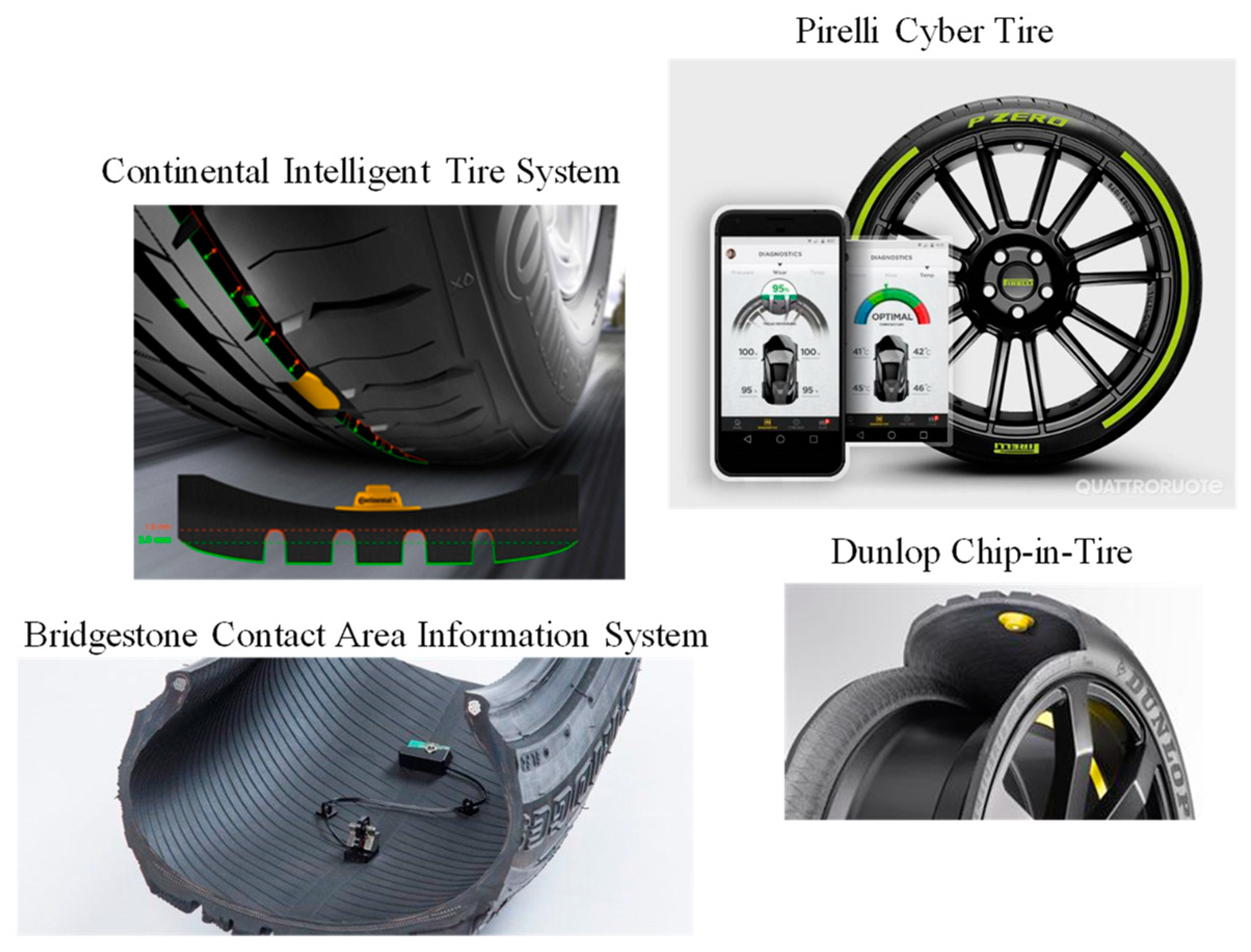
There have been several architectures proposed in the past few years pertaining to smart tires (Figure 2):
- (i)
- The APOLLO program—Developed a 3-in-l intelligent tire [15];
- (ii)
- The FRICTI@N program—On-board system for measuring and estimating tire-road friction [16];
- (iii)
- Contact area information sensing (CAIS) system being developed by Bridgestone [17];
- (iv)
- Cyber Tire being developed by Pirelli Tires [18];
- (v)
- Intelligent tire system being developed by Continental AG [19];
- (vi)
- Intelligent tire system being developed by Hyundai Motor Co, Mando Corp, and Corechips [20];
- (vii)
- Goodyear Dunlop’s chip-in-tire [21].
The key value proposition for the usage of smart tires in vehicles is the potential they offer in improving performance of vehicle control systems. This would be of even more relevance in the case of autonomous vehicles (AVs), considering their high safety requirements.
This paper first presents a comprehensive overview of the state-of-the-art in the field of smart tire technology and thereafter presents details of the work undertaken at the Center for Tire Research (CenTiRe) to develop a smart tire.
The main contributions of this paper are as follows:
- Literature review of the different signal processing techniques used by researchers to extract meaningful information from tire mounted sensors, specifically from tire mounted accelerometers.
- Details about research activities undertaken as part of this study to develop a smart tire.
- Novel algorithms for estimating the tire load and slip angle.
2. Literature Review
There are several signal processing algorithms proposed in literature for estimating the tire load and slip angle. Table 1 presents a summary of the different techniques proposed by researchers.
In view of the above literature review, the following conclusions can be drawn:
- Among the three axes, the radial acceleration signal has been exploited the most by researchers.
- Most of these applications require data to be sampled at high rates. For instance, for tire-road friction sensing, the sensor signal needs to be sampled at 5–10 kHz.
- Both time and frequency domain signal processing techniques have been extensively used.
- Current tire pressure monitoring (TPMS) chips available in production vehicles cannot support such complex signal processing algorithms. Hence, an application specific IC would to be required.
- Since these sensor systems are expected to survive the tire service life, they would require a power source capable of supporting the high sampling rate data processing and high frequency data transmission.
3. Development of a Smart Tire System
Based on their proven reliability for tire application, it was decided to use the tri-axial micro electro mechanical systems (MEMS) accelerometers in this study (Table 2). These sensors offer the advantage of their small dimension, low weight, high reliability, robustness and reliable performance even in harsh and hostile environments.
The smart tire was developed by placing the tri-axial accelerometer on the inner liner of a tire (Figure 3a). The accelerometer was placed on the centerline of the tire footprint. The accelerometer wires were connected to a slip ring placed at the wheel center. Figure 3b shows the final assembly of the instrumented tire with the slip ring. Wires from the slip ring were connected to the data acquisition system. Extensive on-road tests were conducted using the in-house mobile tire test rig shown in Figure 3c.
It is noteworthy to mention that the tri-axial accelerometer was enclosed in latex (rubber) and the latex part was glued to the inner liner. This formed a stronger bond with the tire and reduced the chances of the accelerometer coming loose when the tire is rotated even at high speeds. In addition, duct tape (in combination with cyanoacrylate adhesive) was used to secure the wires of the accelerometers inside the tire. This prevented the wires from pulling on the accelerometer and yanking it out while the tire was rotating.
An example of the measured acceleration signal (unfiltered) for one wheel turn is shown in Figure 4. These measurements were done on a 17-inch SUV tire (size: P245/65R17).
Sharp peaks in the circumferential and radial acceleration signals are indicators of the leading and trailing edges of the tire footprint. More explanations about the measurement setup and the raw acceleration signals recorded can be found in our prior publication [36].
The tire load and slip angle estimation were treated as the lead applications for this study. The motivation for considering these tire states is twofold:
- First, with information about individual tire loads from the tire mounted sensors, the vehicle inertial parameters, namely, vehicle mass, yaw moment of inertia and axle distances from the vehicle center of gravity, can be precisely estimated, thus making the vehicle controller robust against variations in vehicle model parameters.
- Second, it is well known in literature that the vehicle sideslip angle can significantly reduce the risk of accidents through the effective design and implementation of advanced chassis control systems. However, in production vehicles, the sideslip angle is difficult to measure within the desired accuracy level because of high costs and other associated impracticalities. Having a direct measurement of the tire slip angle from a smart tire would enable the design of novel control systems using the tire slip angle as a feedback signal instead of the vehicle sideslip angle.
Specific details of the signal processing algorithms developed as part of this study are given in the subsequent subsections.
4. Algorithm Details
4.1. Tire Load Estimation
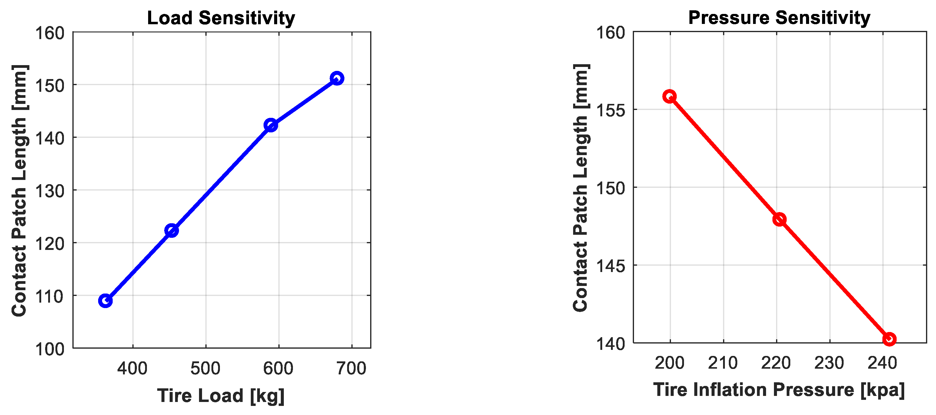
A common approach proposed in literature to estimate the tire load is to exploit the relationship between tire load and the tire contact patch length. A parametric study was conducted to quantify the influence of tire load and other relevant parameters on the tire contact patch length. The patch length was extracted from the tangential acceleration signal by identifying the leading and trailing edge of the tire using a peak detection algorithm. More details regarding the patch length extraction algorithm can be found in a previous publication by the authors [13].
As shown in Figure 5, the tire load and inflation pressure were seen to have a significant impact on the patch length of the tire.
- Higher load results in a longer contact patch length
- Higher inflation pressure results in shorter contact patch length
These results are in-line with results previously published in literature.
What was not so unexpected and in fact not captured in the published literature is the strong correlation seen between the tire wear state (i.e., remaining tread depth) and the tire contact patch length (Figure 6). Lowering the tread depth results in a decrease in the tire circumference (i.e., a shrinkage of the tire radius) and consequently a decrease in the contact patch length.
This poses an issue for the load estimation model. The load model will need to have knowledge of the tire wear state, which by itself presents several technical challenges considering the complexity of typical models required for estimating the remaining tread depth.
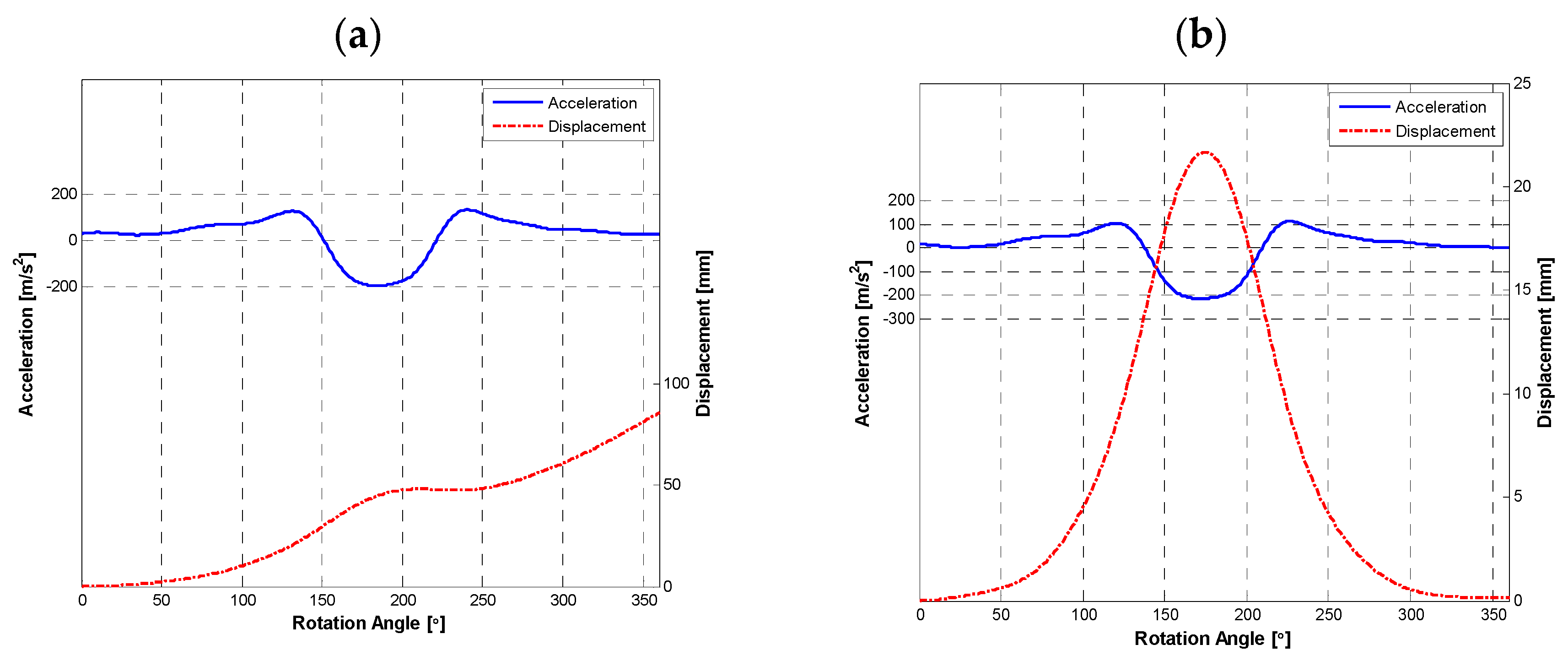
To overcome this challenge, alternative signal features showing a strong correlation with the tire loading state were studied. Knowing that a tire deflects vertically in a linear manner as the load is increased, it was decided to extract the peak radial displacement of the tire from the radial acceleration signal. This requires double integrating the acceleration signal to retrieve displacement. Unfortunately, accelerometers have an unwanted phenomenon called drift, caused by a small DC bias in the acceleration signal. The presence of the drift can lead to large integration errors. If the acceleration signal from a real accelerometer is integrated without any filtering performed, the output could become unbounded over time. To solve the problem of drift, a high-pass filter was used to remove the DC component of the acceleration signal. This is done by carefully extracting the acceleration signal per wheel turn and then applying the high pass filter in conjunction with the integration operation (Figure 7).
By filtering before integrating, the drift error was eliminated, and the radial displacement successfully extracted (Figure 8).
Finally, the amplitude of the peak radial displacement of the tire was extracted from the displacement curve. The radial displacement shows the near linear correlation with the tire load and inflation pressure (Figure 9).
It is important to mention that it would be incorrect to generalize that the tire behavior will always be linear under all loading and inflation pressure conditions. The linear behavior observed is specifically under the range of loads and inflation pressures considered in this study.
More interestingly, in comparison to the tire contact patch length, the amplitude of the peak radial displacement showed a much higher sensitivity to the tire load (Table 3). Moreover, the radial displacement shows negligible sensitivity to the tire tread depth. This makes radial displacement a more attractive feature in comparison to the contact patch length and hence was the preferred feature for this study.
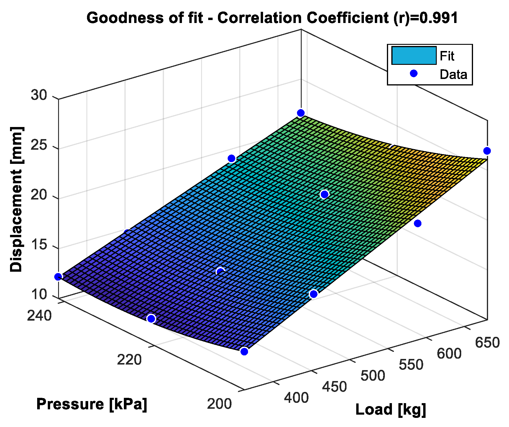
A model capturing the dependencies between the tire radial displacement, load and inflation pressure was fit (Figure 10). A polynomial fit with the second-order in pressure and the first-order in the load provided a good model fit.
Equation (1) can be rewritten into a standard parameter identification form as follows:
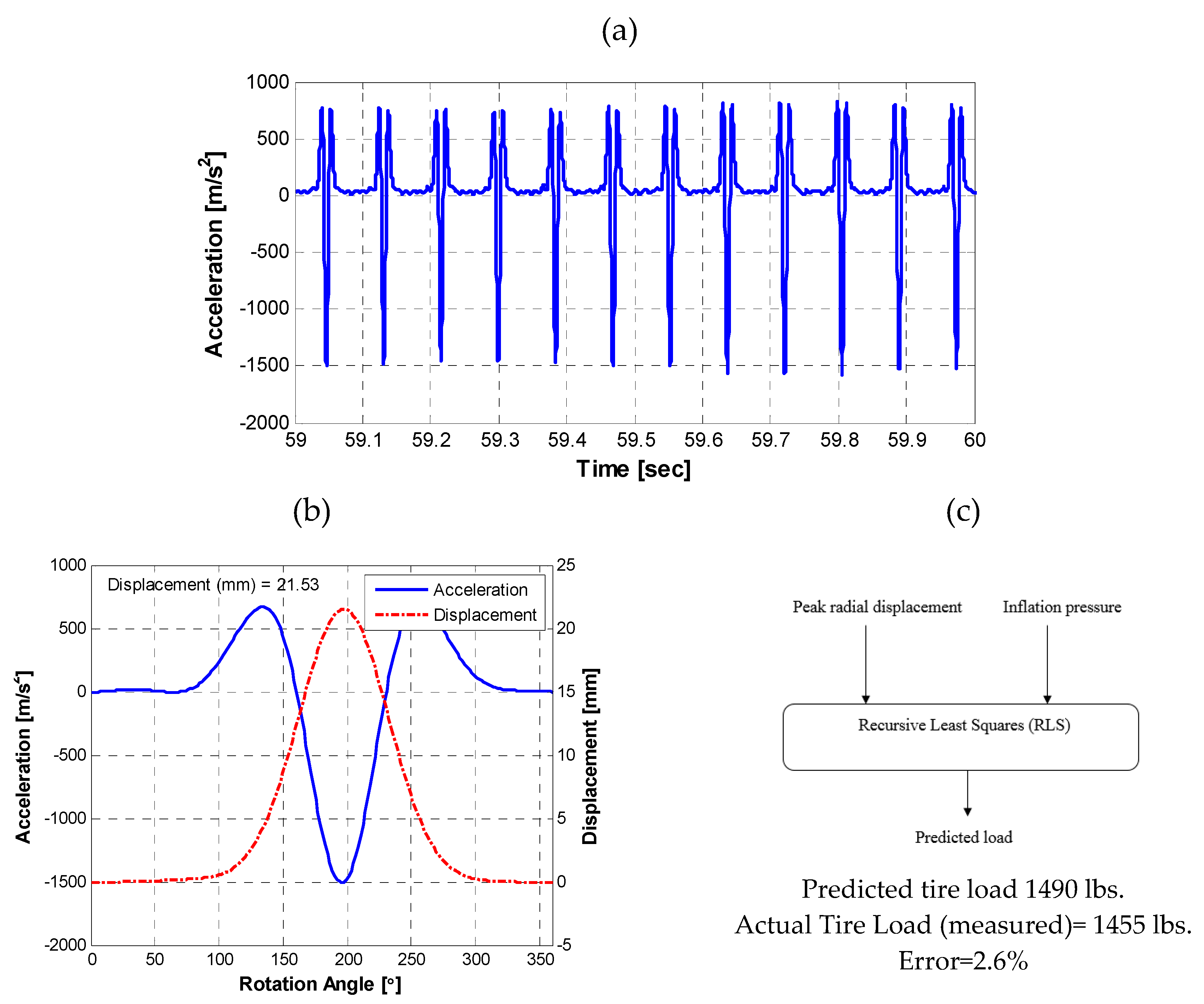
The unknown parameter can be identified in real-time using the parameter identification approach. The recursive least squares (RLS) algorithm [37] provides a method to iteratively update the unknown parameter at each sampling time to minimize the sum of the squares of the modeling error using the past data contained within the regression vector, . The performance of the RLS algorithm was evaluated through experimental road vehicle tests. The vehicle maneuver was straight driving with intermittent gas pedal presses (Figure 11).
The RLS model was found to predict the tire load within the first 20 wheel rotations. The estimation error was 2.6%. For the sake of completeness, the same dataset was also used to evaluate the performance of a contact patch length based load estimation model. The estimation error was found to be 5.3%. So, a radial deflection based model was found to be superior than the contact patch length based model.
4.2. Tire Slip Angle Estimation
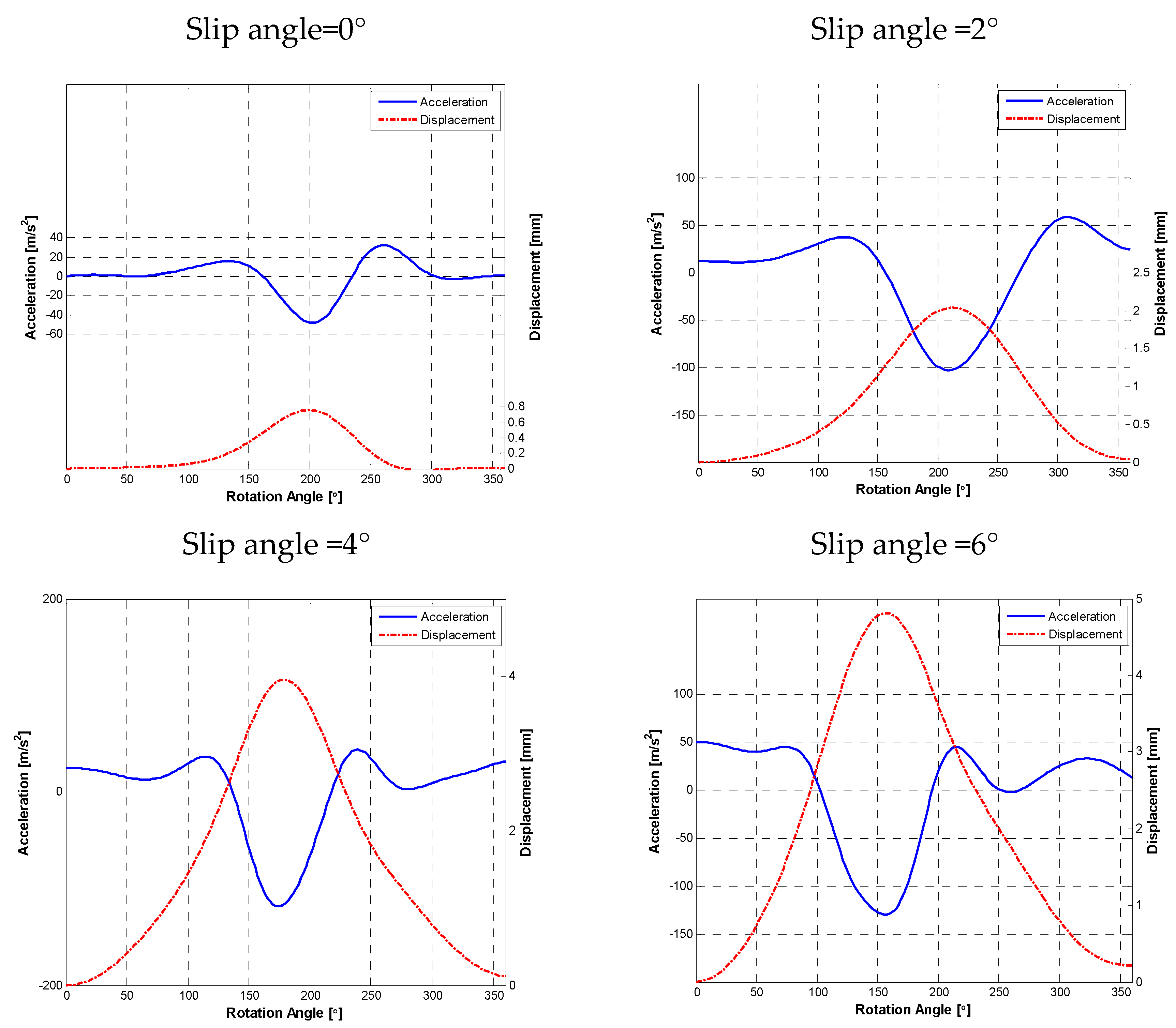
Using the procedure described in Figure 7, the lateral displacement profile of the tire footprint was extracted from the lateral acceleration signal at different tire slip angles (Figure 12).
The following observations were made:
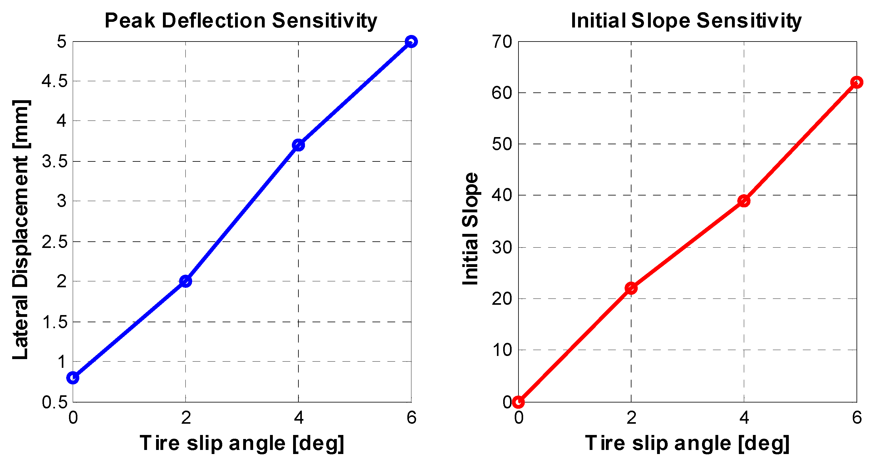
- The maximum lateral displacement of the tire footprint increases as the slip angle increases.
- The slope of the initial linear part of the lateral displacement profile also increases as the slip angle increases.
Both of these features were found to be linearly correlated with the tire slip angle (Figure 13).
A multiple linear regression model (Equation (3)) was trained using both these signal features and found to estimate the tire slip angle with an accuracy of +/− 0.2 deg.
It is noteworthy to mention that the correlation between the lateral displacement of the footprint and the tire slip angle only holds true when the tire is deforming. Once the tire force saturates and the footprint starts to slide, this relationship does not hold true anymore. Future work will focus on understanding the lateral acceleration signal during high slip angle maneuvers and extracting signal features that correlate with the slip angle even when the tire is sliding.
5. Conclusions
This paper provides a review of relevant works about the different signal processing techniques proposed by researchers to extract the tire load and slip angle information from tire mounted accelerometers. Details about research activities undertaken as part of this study to develop a smart tire are presented. Novel algorithms for the tire load and slip angle estimation are presented. The tire load is estimated by extracting the peak radial deflection of the tire from the radial acceleration signal. The tire slip angle is estimated by extracting the peak lateral deflection and the slope of the lateral deflection curve from the lateral acceleration signal. Multiple linear regression models are used to model the relationship between the identified signal features of interest and tire load, slip angle. It is noteworthy to mention that the motivation for using linear regression models is the low computational burden imposed while doing the real-time implementation of these models in the vehicle electronic control unit (ECU). Non-linear models are expected to give better fits; however, they also need more compute resources, which poses implementation challenges. This is expected to improve as the next generation vehicles are expected to come equipped with more sophisticated processing units to enable advanced driver-assistance system (ADAS) functionalities. Future work will focus on using the tire load and slip angle information to enhance the robustness of the vehicle state estimators.
Key challenges for the large-scale industrialization of smart tire technology are as follows:
- For the installation of sensors in a tire, many problems will need to be considered, such as the compatibility of the sensors with the tire rubber i.e., stiffness issues, robustness of sensor in the harsh tire environment, wireless transmission of gathered data in an energy efficient manner, economic issues relating to the use of expensive sensors in a comparatively inexpensive product, the tire and finally meeting the power requirements of all the electronic components.
- Most studies have assessed the benefits of a smart tire for control systems in a simulation environment. It remains to be foreseen how much of this benefit can be captured in the real-world, considering that most smart tires use a single point sensing solution transmitting data at a low frequency.
- It is also concluded that the current tire pressure monitoring chips available in the production vehicles cannot support complex signal processing algorithms required to extract signal features from tire mounted sensors. Hence, an application specific integrated chip (ASIC) would be required.
Author Contributions
Conceptualization, K.B.S. and S.T.; Methodology, K.B.S. and S.T.; Validation, K.B.S; Writing—Original Draft Preparation, K.B.S.; Writing—Review and Editing, K.B.S.
Funding
This research received no external funding.
Conflicts of Interest
The authors declare no conflict of interest.
References
- Sabbioni, E.; Kakalis, L.; Cheli, F. On the impact of the maximum available tire-road friction coefficient awareness in a brake-based torque vectoring system. SAE Tech. Pap. 2010. [Google Scholar] [CrossRef]
- Braghin, F.; Cheli, F.; Melzi, S.; Sabbioni, E.; Mancosu, F.; Brusarosco, M. Development of a cyber tire to enhance performances of active control systems. In Proceedings of the 7th EUROMECH Solid Mechanics Conference (ESMC 2009), Lisbon, Portugal, 7–11 September 2009; pp. 1–9. [Google Scholar]
- Cheli, F.; Leo, E.; Melzi, S.; Sabbioni, E. On the impact of ‘smart tyres’ on existing ABS/EBD control systems. Veh. Syst. Dyn. 2010, 48, 255–270. [Google Scholar] [CrossRef]
- Erdogan, G.; Hong, S.; Borrelli, F.; Hedrick, K. Tire Sensors for the Measurement of Slip Angle and Friction Coefficient and Their Use in Stability Control Systems. SAE Int. J. Passeng. Cars Mech. Syst. 2011, 4, 44–58. [Google Scholar] [CrossRef]
- Cheli, F.; Sabbioni, E.; Sbrosi, M.; Brusarosco, M.; Melzi, S.; D’alessandro, V. Enhancement of ABS Performance through On-Board Estimation of the Tires’ Response by Means of Smart Tires; SAE Technical Paper; SAE International: Warrendale, PA, USA, 2011. [Google Scholar]
- Cheli, F. Cyber Tyre: A Novel Sensor to Improve Vehicle’s Safety; SAE Technical Paper; SAE International: Warrendale, PA, USA, 2011. [Google Scholar]
- National Highway Traffic Safety Administration. Proposed New Pneumatic Tires for Light Vehicles. FMVSS No. 139. Available online: https://www.nhtsa.gov/sites/nhtsa.dot.gov/files/tp-139-02.pdf (accessed on 25 April 2019).
- 106th Congress. Transportation Recall Enhancement Accountability, and Documentation (TREAD) Act. Available online: https://www.congress.gov/106/plaws/publ414/PLAW-106publ414.pdf (accessed on 25 April 2019).
- National Highway Traffic Safety Administration. Federal Motor Vehicle Safety Standards; Tire Pressure Monitoring Systems; Controls and Displays; National Highway Traffic Safety Administration: Washington, DC, USA, 2000.
- 70 FR 18135—Federal Motor Vehicle Safety Standards; Tire Pressure Monitoring Systems; Controls and Displays—Content Details—05-6741. Available online: https://www.govinfo.gov/app/details/FR-2005-04-08/05-6741 (accessed on 19 April 2019).
- Singh, K.B.; Arat, M.A.; Taheri, S. Enhancement of collision mitigation braking system performance through real-time estimation of tire-road friction coefficient by means of smart tires. SAE Int. J. Passeng. Cars Electron. Electr. Syst. 2012, 5, 607–624. [Google Scholar] [CrossRef]
- Arat, M.A.; Singh, K.B.; Taheri, S. An intelligent tyre based adaptive vehicle stability controller. Int. J. Veh. Des. 2014, 65, 118–143. [Google Scholar] [CrossRef]
- Singh, K.B.; Arat, M.A.; Taheri, S. An intelligent tire based tire-road friction estimation technique and adaptive wheel slip controller for antilock brake system. J. Dyn. Syst. Meas. Control 2013, 135, 031002. [Google Scholar] [CrossRef]
- Arat, M.A. Development and Improvement of Active Vehicle Safety Systems by means of Smart Tire Technology; Virginia Polytechnic Institute and State University: Blacksburg, VA, USA, 2013. [Google Scholar]
- Apollo Main Page. Available online: http://virtual.vtt.fi/virtual/proj3/apollo/ (accessed on 19 April 2019).
- EU Project Friction. Available online: http://friction.vtt.fi/ (accessed on 19 April 2019).
- Sensing Technologies. Bridgestone. Available online: https://www.bridgestone.com/technology_innovation/cais/ (accessed on 21 April 2019).
- Pirelli, Schrader Team up for Computerized ‘Cyber Tire’. Available online: https://www.motorauthority.com/news/1044745_pirelli-schrader-team-up-for-computerized-cyber-tire (accessed on 19 April 2019).
- Continental’s Intelligent Tire. Available online: https://www.continental-tires.com/transport/products/continental-itire (accessed on 19 April 2019).
- Jo, H.Y.; Yeom, M.; Lee, J.; Park, K.; Oh, J. Development of Intelligent Tire System; SAE Technical Paper; SAE International: Warrendale, PA, USA, 2013. [Google Scholar]
- Goodyear Dunlop’s Chip-In-Tyre Shows Latest in Intelligent Tyre Technology: Tyrepress. Available online: https://www.tyrepress.com/2014/03/goodyear-dunlops-chip-in-tyre-shows-latest-in-intelligent-tyre-technology/ (accessed on 19 April 2019).
- Mancosu, F.; Brusarosco, M.; Arosio, D. Method and System for Determining a Tyre Load during the Running of a Vehicle. U.S. Patent 7404317B2, 29 July 2008. [Google Scholar]
- Schillinger, J.; Von Lutz, R.; Cyllik, A.; Lehmann, J. Sensor Transponder and Procedure for Measuring Tire Contact Lengths and Wheel Load. U.S. Patent 7536903B2, 26 May 2009. [Google Scholar]
- Wagner, M.; Troeger, H. Method for Monitoring the Load of Vehicle Tires. U.S. Patent 8742911B2, 3 June 2014. [Google Scholar]
- Tebano, R.; Audisio, G.; Fioravanti, A.P. Method and System for Estimating the Load Acting on a Tire. U.S. Patent 20130261991A1, 3 October 2013. [Google Scholar]
- Brusarosco, M.; Mancosu, F.; Arosio, D. Method and System for Determining a Tyre Load during the Running of a Motor Vehicle. U.S. Patent 7945361B2, 17 May 2011. [Google Scholar]
- Teerhuis, A.; Schmeitz, A.; van de Molengraft-Luijten, L. Tire state estimation based on measured accelerations at the tire inner liner using an Extended Kalman Filter design. In Proceedings of the 4th International Tyre Colloquium, Guildford, UK, 20–21 April 2015. [Google Scholar]
- Krier, D.; Zanardo, G.S.; del Re, L. A PCA-based Modeling Approach for Estimation of Road-tire Forces by In-tire Accelerometers. IFAC Proc. Vol. 2014, 47, 12029–12034. [Google Scholar] [CrossRef]
- Dharamshi, P.; Haas, T.; Kretschmann, M.; Spotka, J. Method and System for Determining a Wheel Load Acting on a Tire of a Vehicle. U.S. Patent 20170355234A1, 14 December 2017. [Google Scholar]
- Schmeitz, A.J.C.; Teerhuis, A.P. Robustness and Applicability of a Model-Based Tire State Estimator for an Intelligent Tire. Tire Sci. Tech. 2018, 46, 105–126. [Google Scholar] [CrossRef]
- Masago, T. Tire Load Estimation Method and Tire Load Estimation Device. U.S. Patent 20190025113A1, 24 January 2019. [Google Scholar]
- Mancosu, F.; Brusarosco, M.; Arosio, D. Method and System for Determining a Cornering Angle of a Tyre during the Running of a Vehicle. U.S. Patent 7552628B2, 30 June 2009. [Google Scholar]
- Mancosu, F.; Brusarosco, M.; Arosio, D. Method and System for Determining a Cornering Angle of a Tyre during the Running of a Vehicle. U.S. Patent 8024087B2, 20 September 2011. [Google Scholar]
- Matsuzaki, R.; Kamai, K.; Seki, R. Intelligent tires for identifying coefficient of friction of tire/road contact surfaces. Sens. Smart Struct. Technol. Civ. Mech. Aerosp. Syst. 2015, 9435, 94350A. [Google Scholar]
- PCB Model 356A01. Available online: http://www.pcb.com/Products/model/356A01 (accessed on 21 April 2019).
- Singh, K.B. Development of an Intelligent Tire Based Tire-Vehicle State Estimator for Application to Global Chassis Control; Virginia Tech: Blacksburg, VA, USA, 2012. [Google Scholar]
- Vahidi, A.; Stefanopoulou, A.; Peng, H. Recursive least squares with forgetting for online estimation of vehicle mass and road grade: theory and experiments. Veh. Syst. Dyn. 2005, 43, 31–55. [Google Scholar] [CrossRef]
Figure 1.
Smart tire system sensor output.
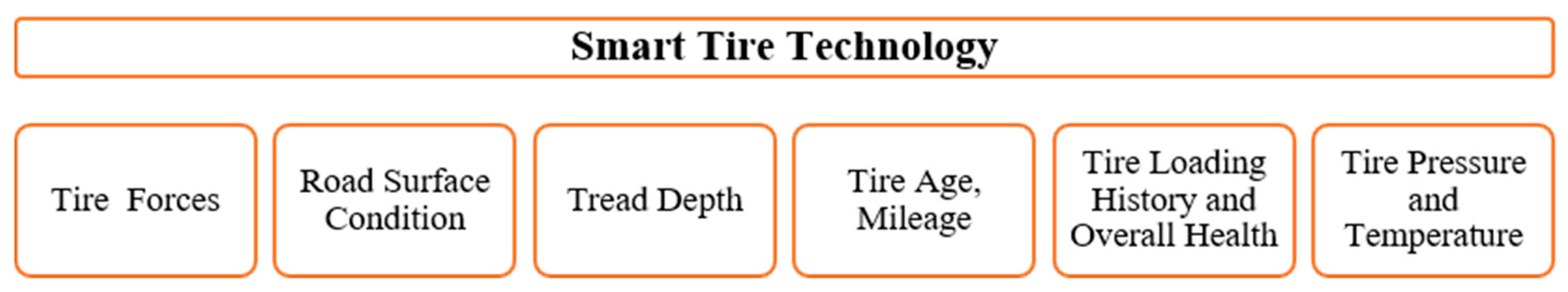
Figure 2.
Smart tire system—products and concepts.

Figure 3.
Smart tire application: (a) Sensor mounted on the tire footprint centerline; (b) instrumented tire assembly with a high-speed slip ring; (c) mobile tire test rig.
Figure 3.
Smart tire application: (a) Sensor mounted on the tire footprint centerline; (b) instrumented tire assembly with a high-speed slip ring; (c) mobile tire test rig.
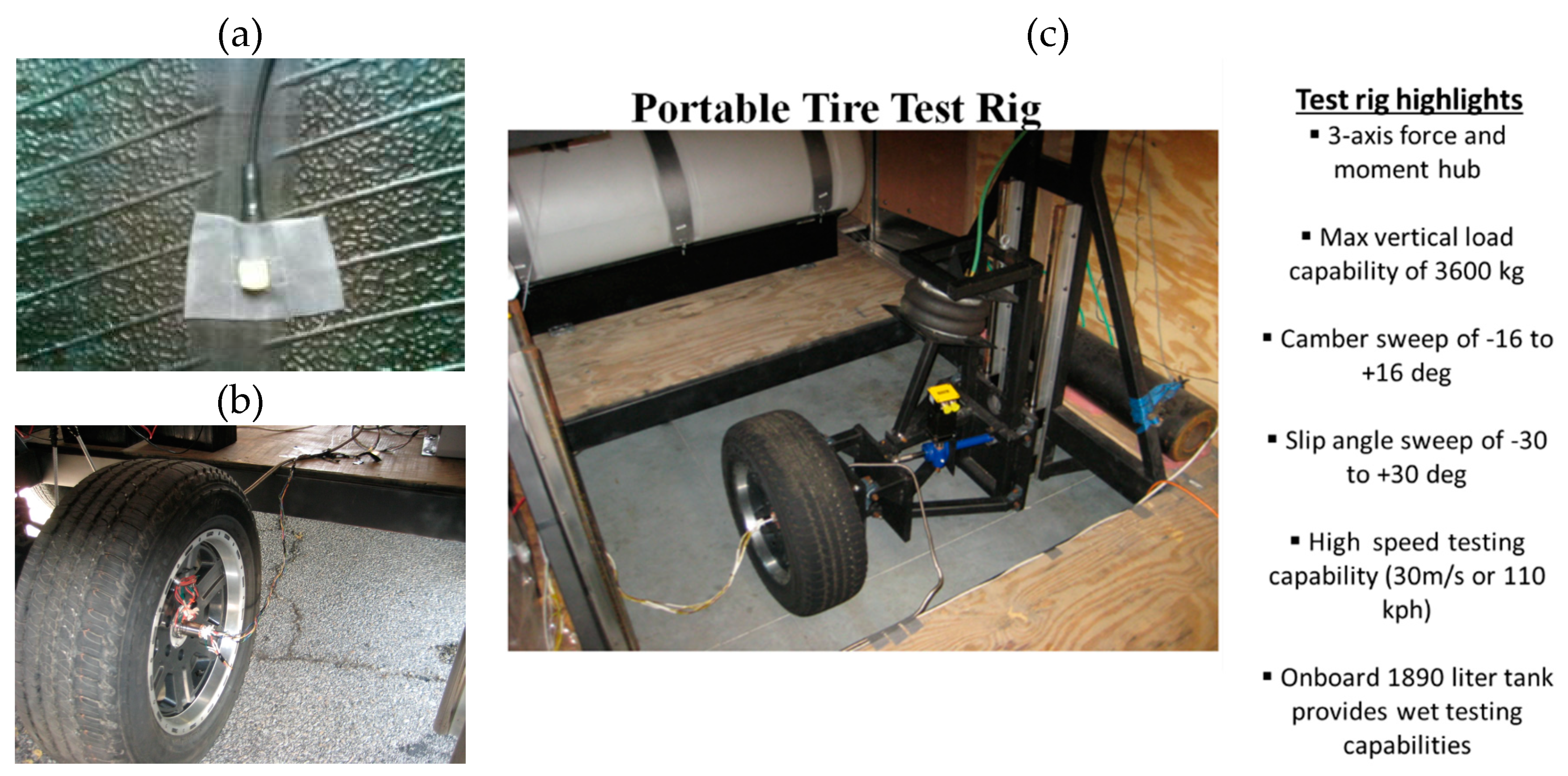
Figure 4.
Signal for one wheel turn from a tire attached tri-axial accelerometer.
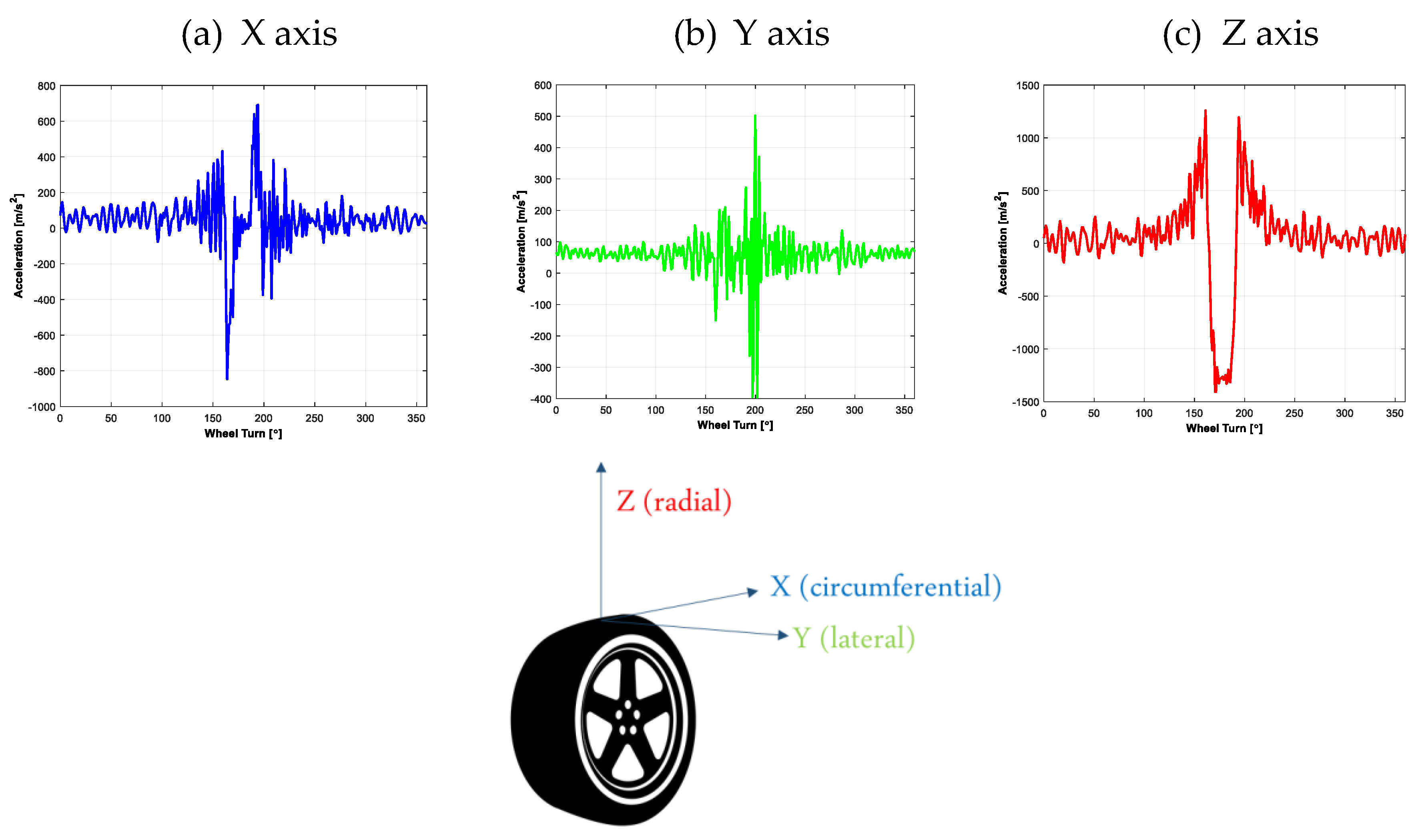
Figure 5.
Impact of load and inflation on the tire contact patch length. Tire Size: P245/65R17.

Figure 6.
Impact of remaining tread depth on the tire contact patch length. Tire Size: P245/65R17.
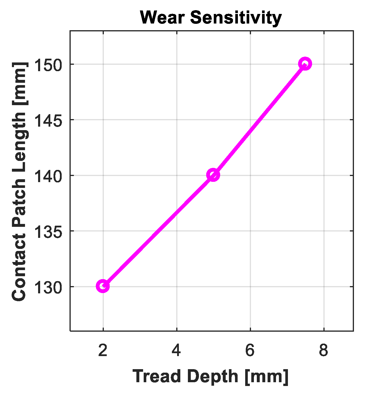
Figure 7.
Algorithm for retrieving radial displacement from the acceleration signal.
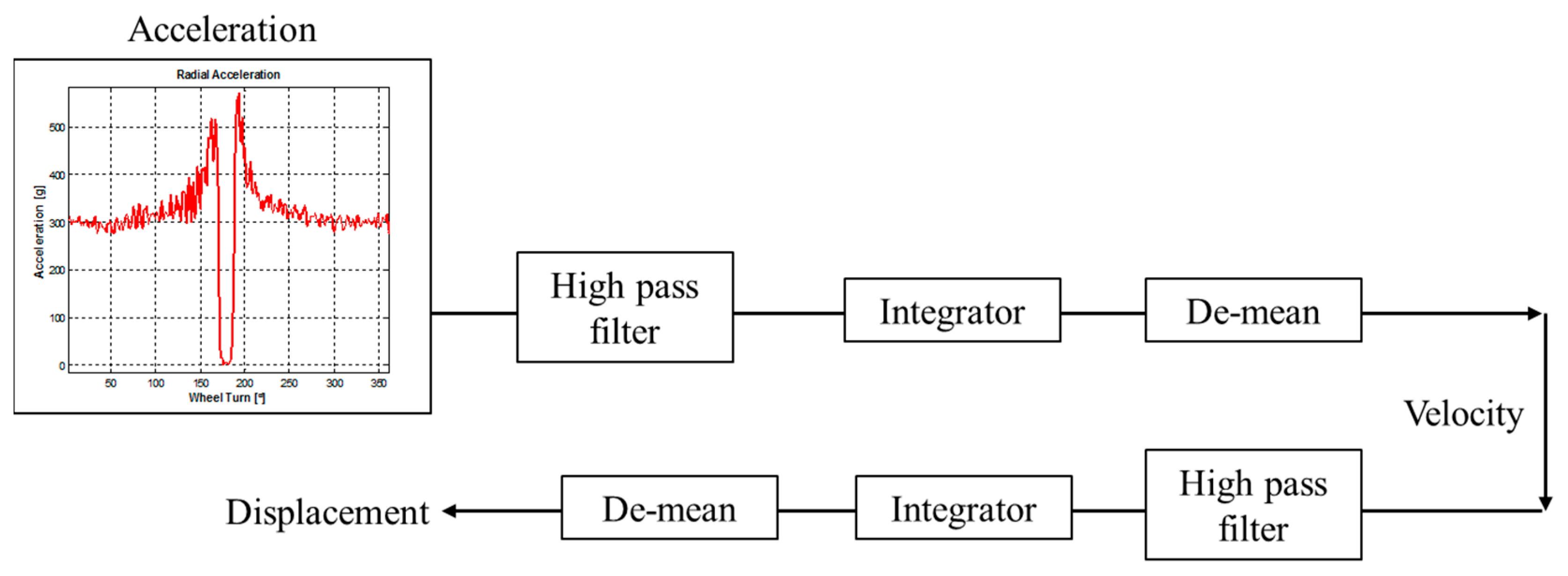
Figure 8.
(a) Integration without filtering; (b) integration with filtering.

Figure 9.
Impact of load and inflation on the tire vertical displacement. Tire Size: P245/65R17.
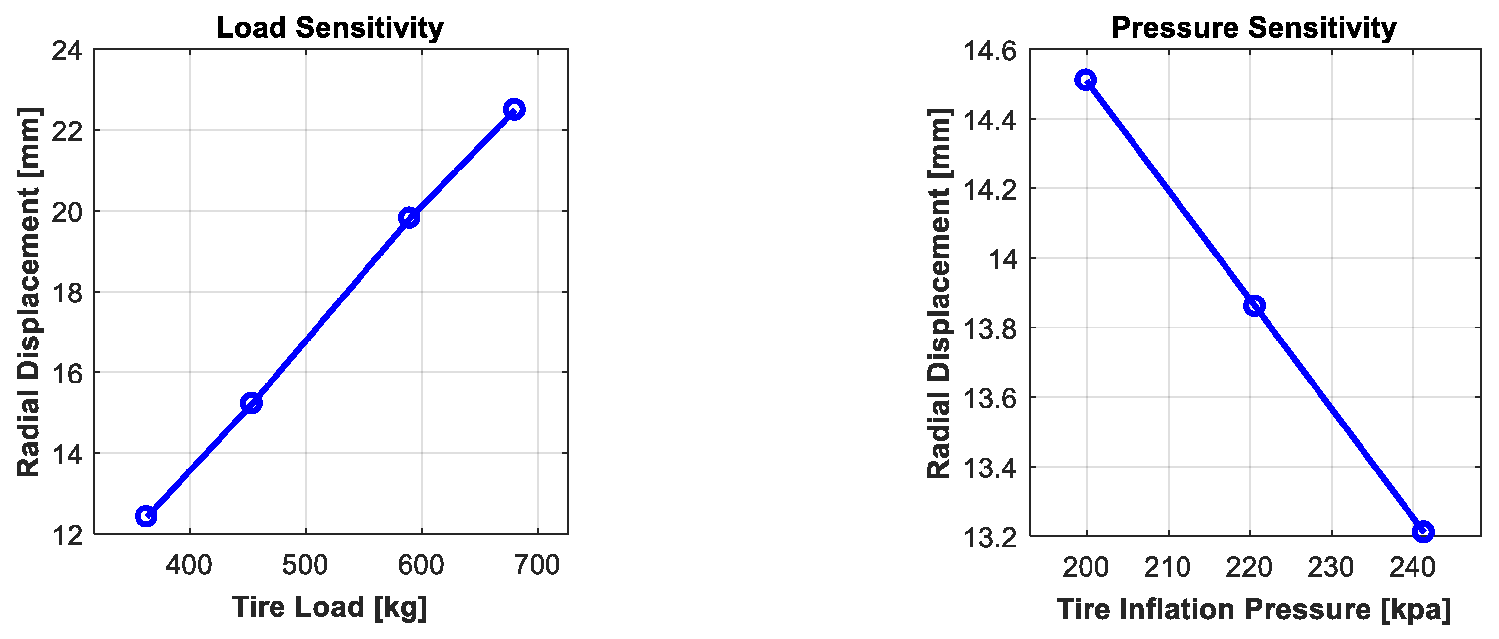
Figure 10.
Model fitting. Tire Size: P245/65R17, speeds tested: 25, 50, 75, 100 kph, camber = 0 deg.
Figure 10.
Model fitting. Tire Size: P245/65R17, speeds tested: 25, 50, 75, 100 kph, camber = 0 deg.

Figure 11.
Prediction performance. (a) Raw measurement—straight-line driving; (b) feature extraction; (c) RLS prediction model.
Figure 11.
Prediction performance. (a) Raw measurement—straight-line driving; (b) feature extraction; (c) RLS prediction model.

Figure 12.
Extraction of lateral displacement from the lateral acceleration signal at different tire slip angles.
Figure 12.
Extraction of lateral displacement from the lateral acceleration signal at different tire slip angles.

Figure 13.
Correlation between extracted features and the tire slip angle.

Table 1.
State-of-the-art literature review—analysis of tire accelerometer data.
| Estimated State | Signal Used | Underlying Physics | Reference |
|---|---|---|---|
| Tire vertical force | Radial acceleration | Use an empirical model between tire contact patch length and tire load | [22,23,24,25] |
| Use an empirical model correlating the radial acceleration amplitude to the tire load | [26] | ||
| Use an empirical model to describe the shape of the radial acceleration signal—Vertical load is treated as an unknown parameter and is estimated used an EKF observer | [27] | ||
| Use Principal Component Analysis, to describe smart tire signal variance by means of a few linear projections. Projections are correlated linearly with the contact forces | [28] | ||
| Use a model between tire contact patch length, tire load and the tire operation conditions (toe) for a respective tire type and/or respective physical properties of the tire | [29] | ||
| Assess the real-time applicability of a tire vertical force estimator on a standard platform used for rapid control prototyping on vehicles | [30] | ||
| Use a model correlating the tire ground contact time to tire load, where the contact time is extracted from the differential acceleration waveform | [31] | ||
| Tire slip angle | Radial acceleration | Monitor change in the footprint length at the centerline and shoulder positions to estimate the tire slip angle | [32] |
| Lateral acceleration | Correlate lateral acceleration amplitude with the tire slip angle | [33] | |
| Extract lateral deformation from the acceleration signal and correlate that with the tire slip angle | [34] |
Table 2.
Tri-axial accelerometer characteristics [35].
Table 2.
Tri-axial accelerometer characteristics [35].
| Accelerometer Characteristics | |
|---|---|
| Range | ±5000 g |
| Sensitivity | 1 mv/g |
| Frequency response | 1.2–10 kHz |
| Resonance frequency | 30 kHz |
| Mass | 3.0 g |
| Dimensions | 17.7 × 9.02 × 9.14 mm |
Table 3.
Sensitivity analysis—impact of load, pressure and tire wear change on the tire radial displacement and contact patch length.
Table 3.
Sensitivity analysis—impact of load, pressure and tire wear change on the tire radial displacement and contact patch length.
| Load (kg) | Pressure (kPa) | Tread Depth (mm) | |
|---|---|---|---|
| Range Tested | 350 kg–680 kg | 200–240 kPa | 2mm–8mm |
| % Change in the Peak Radial Displacement | 80–90% | 10–15% | negligible |
| % Change in the Contact Patch Length | 40–50% | 10–15% | 15–20% |
© 2019 by the authors. Licensee MDPI, Basel, Switzerland. This article is an open access article distributed under the terms and conditions of the Creative Commons Attribution (CC BY) license (http://creativecommons.org/licenses/by/4.0/).
Share and Cite
MDPI and ACS Style
Singh, K.B.; Taheri, S. Accelerometer Based Method for Tire Load and Slip Angle Estimation. Vibration 2019, 2, 174-186. https://doi.org/10.3390/vibration2020011
AMA Style
Singh KB, Taheri S. Accelerometer Based Method for Tire Load and Slip Angle Estimation. Vibration. 2019; 2(2):174-186. https://doi.org/10.3390/vibration2020011
Chicago/Turabian StyleSingh, Kanwar Bharat, and Saied Taheri. 2019. "Accelerometer Based Method for Tire Load and Slip Angle Estimation" Vibration 2, no. 2: 174-186. https://doi.org/10.3390/vibration2020011