1. Introduction
Confined spaces such as reactors and storage tanks containing combustible gases are often connected through pipes to form a vessel-pipe-vessel structure. Due to corrosion, operational errors, and other factors, oxidizing gases are prone to mixing in, and explosion accidents are likely to occur when the explosive limit is reached. In actual explosion conditions, the complex structure of the device and the long pipes lead to uneven distribution of combustible gases and formation of concentration gradients. The gas explosion dynamic evolution mechanism of such linked vessels with concentration gradient is significantly different from that of uniform concentration. In-depth research in this field can provide key guidance for engineering applications.
Studies on gas explosions in confined spaces can be divided into two categories according to spatial shape: single-shape vessels (single vessel/pipe) and linked vessels; and according to gas concentration distribution: uniform concentration and non-uniform concentration (concentration gradient).
Numerous scholars have investigated gas explosions in vessels of simple geometry. In terms of theoretical research, Deng [
1] explored the explosion limit, explosion pressure, and other parameters of methane under static and turbulent conditions. He and Yang [
2,
3] revealed the flame propagation mechanism of gas explosion in slender pipes. Li [
4] found through experiments that turbulence can accelerate the explosion combustion velocity and increase the explosion pressure. Kerampran [
5] pointed out that pipe length and initial flame velocity have significant effects on the explosion flame propagation of combustible gases such as propane in pipes. Hu [
6] found that the explosion overpressure and pressure rise rate first increase and then decrease with the increase of gas concentration, and that the ignition position exerts a significant influence on the maximum pressure rise rate. Ivanov [
7,
8] studied the deflagration to detonation transition (DDT) process of hydrogen in pipes. Liu [
9] analyzed the explosion propagation laws of low-concentration coal dust-gas mixtures for particles of different sizes in an explosion tube. Researchers at home and abroad have also studied the influence of initial conditions such as ignition position, ignition energy, initial temperature, and pressure on the explosion characteristics in vessels [
10]. Van [
11] found that lowering the ignition position along the vertical axis of the vessel increases both the flame propagation volume and explosion pressure of methane explosion. Lyu [
12] confirmed that the increase of ignition energy can improve the flame propagation velocity. Zhuang [
13] explored the influence of ignition position on hydrogen explosion pressure and flame instability in a cylindrical confined space. Xu [
14] pointed out that a strong fire source can accelerate elementary reactions, leading to an increase in explosion overpressure and pressure rise rate. Zhang [
15] constructed a theoretical model to predict the critical initiation energy of gas explosion and clarified its relationship with the initial state of the gas. Gieras [
16] showed that the higher the initial temperature, the wider the upper and lower explosion limits of methane. Mitu [
17] found that the maximum pressure rise rate changes linearly with the initial pressure, and the pressure rise rate and deflagration index of spherical vessels are larger than those of cylindrical vessels. Li [
18] concluded that the maximum explosion pressure and maximum pressure rise rate of methane increase with the increase of initial pressure and concentration. Luo [
19] pointed out that the increase of initial temperature will lead to an increase in the maximum pressure rise rate of CO and CH
4. Cheng [
20] investigated the explosion characteristics of low-temperature hydrogen-air mixtures, and the results show that reducing the initial temperature can significantly enhance the explosion severity. Ma [
21] established a theoretical model to predict the lower explosion limits of multi-combustible gases under different temperature conditions. Zhou [
22,
23] studied the influence of vessel size on explosion overpressure, flame front, and other parameters.
Currently, most studies on explosions of non-uniform premixed combustible gases focus on vertical concentration gradients (concentration gradient exists in the pipe cross-section). Wang [
24] showed through experiments that vertical concentration distribution has a significant influence on the flame propagation velocity and maximum explosion pressure of methane explosion. Boeck [
25,
26] found that compared with uniform concentration, the explosion flame of hydrogen with vertical concentration gradient accelerates faster and the pressure rises faster. Zhang [
27] explored the influence of three ignition positions (top, center, and bottom) in the pipe on the flame propagation velocity, maximum temperature, maximum overpressure, and maximum pressure rise rate of methane explosion with vertical concentration gradient. Khodadadi [
28] pointed out that the flame velocity of hydrogen explosion with vertical concentration gradient is larger, while uniform hydrogen explosion has greater flame acceleration and faster initiation process. Cruz [
29] found that the laminar flame velocity of methane with vertical concentration gradient is lower than that of uniform mixtures. Yang [
30] examined the mechanisms through which concentration gradients and ignition positions affect the hydrogen explosion process, revealing that concentration gradients suppress flame propagation. Wu [
31] found that larger concentration gradients lead to lower flame propagation speeds and more intense pressure oscillations. Wu [
32] investigated the coupled effects of concentration gradients and obstacle blockage ratios on methane explosion flames. Regarding horizontal concentration gradients (gradients along the length of the duct), some scholars have conducted relevant studies. Li [
33] experimentally examined the influence of horizontal concentration gradients on explosion dynamics and flame propagation in methane-filled ducts, demonstrating that concentration gradients can suppress both explosion overpressure and flame propagation. Zheng [
34] examined how blockage ratio and non-uniform methane distribution influence explosion overpressure and flame propagation, drawing the conclusion that the most severe explosion overpressure occurs when the gas distribution in the duct is relatively uniform. Through experiments and CFD simulations, Sulaiman [
35] investigated the explosibility and severity characteristics of rice flour under different concentrations and ignition delay times, and found that rice flour exhibits higher explosibility when the ignition delay time exceeds 60 ms. Based on the comprehensive research, horizontal concentration gradients consistently reduce the flame propagation velocity. In contrast, vertical concentration gradients exhibit contradictory conclusions regarding their impact on flame propagation velocity, depending on the gas type or the magnitude of the concentration gradient. This phenomenon is closely related to differences in the reaction activity of various gases, as well as variations in mixing and turbulence effects induced by different gradient magnitudes. A detailed analysis is presented in
Table 1.
Compared with single vessels, the explosion mechanism of linked vessels is complex and involves many influencing factors. Some scholars have carried out research on the explosion consequences and influencing factors of linked vessels. Michele [
36] found through numerical simulation that the explosion flame flows back to the initiating vessel due to the effect of the wall of the flame-transmitting vessel, and the huge backflow accelerates the combustion reaction of the initiating vessel. Liu [
37] pointed out that the flame will extinguish when the pipe diameter of the linked vessel is too small. Domnina [
38] showed through experiments that vessel shape, volume ratio, and ignition position all affect the explosion overpressure. Wang [
39,
40,
41,
42,
43,
44,
45] studied the explosion process of linked vessels and the influence of pipe diameter on explosion characteristics through experiments and numerical simulations, and found that the smaller the diameter, the larger the explosion pressure rise rate. Shi [
46] showed through comparative analysis that the maximum explosion pressure rise rate of linked vessels is higher than that of single vessels. You [
47] found through experiments that when the pipe length increases, the explosion pressure and pressure rise rate of the flame-transmitting vessel increase, while the changes of explosion parameters of the initiating vessel are small. Lu [
48] investigated the deflagration-to-detonation transition (DDT) suppression characteristics of multi-layer metal wire mesh and aluminum silicate wool on methane/air mixtures in linked vessels by means of experimental methods. Yin [
49] investigated the occurrence conditions and propagation characteristics of deflagration-to-detonation transition (DDT) in methane-air mixtures within linked vessels under different pipe lengths and inner diameters. The results indicated that compared with a single pipe, the DDT induction distance in linked vessels is relatively shorter.
In summary, existing research on combustible gas explosions suffers from notable limitations: First, most studies center on single-shape vessels (single vessel/pipe) or uniform concentration conditions, yet insufficient attention has been devoted to the coupled system of concentration gradients and linked vessels that is prevalent in industrial scenarios, resulting in a paucity of systematic investigations aligned with real-world engineering environments; Second, while certain studies have examined the individual impacts of concentration gradients or ignition positions, few have thoroughly elucidated the dynamic evolutionary mechanisms of explosion parameters in linked vessels under the synergistic interaction of these two factors. Therefore, this study will focus on the influence of ignition position on the explosion characteristics of linked vessels with a concentration gradient. Considering the limited physical parameters obtained by experimental methods, numerical simulation is adopted for in-depth research.
2. Research Object and Methods
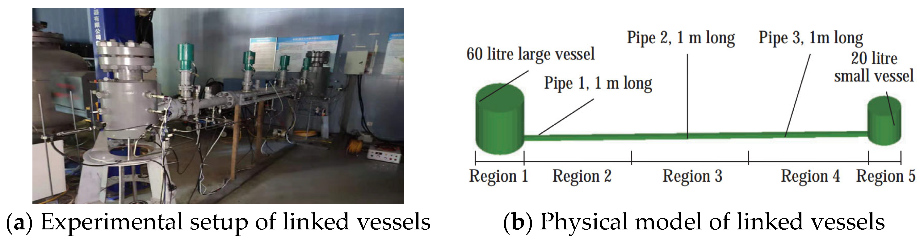
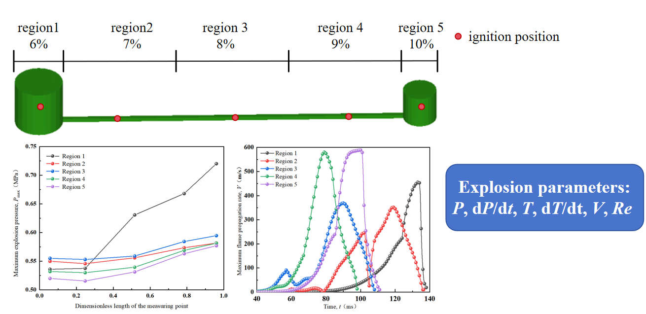
Fluidyn (Version V6) is a mature commercial software developed based on computational fluid dynamics (CFD) principles for fire and explosion numerical simulation. The physical diagram and physical model diagram of the linked vessels experimental device are shown in
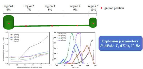
Figure 1. The volume of the large vessel is 60 L, and the volume of the small vessel is 20 L. The ratio of diameter to height of both vessels is 1:1. The two vessels are linked at the bottom by a square pipe with a cross-sectional area of 0.035 m × 0.035 m and a length of 3 m. To study the concentration gradient, the linked device is divided into 5 regions, which are sequentially the large vessel region 1, 1 m-long pipe regions 2 to 4, and the small vessel region 5. In the experimental device, pressure sensors are installed at the geometric center of each region. In the numerical simulation, in addition to pressure, parameters such as temperature, flame speed, and Reynolds number are also measured.
In the geometric model of the numerical simulation, all walls adopt no-slip and no-mass penetration boundary conditions. The heat loss of the flame to the external environment through the wall via thermal radiation and convection during the vessel explosion is not considered, and the adiabatic boundary condition is adopted in the calculation process. The initial conditions of the combustible gas are set as a pressure of 105 Pa and an initial temperature of 300 K. To ensure the accuracy of the simulation results and improve the calculation efficiency, a grid independence analysis was carried out, and finally, the grid was divided into 156,244 unstructured grids.
To verify the reliability of the numerical simulation, a comparative analysis of the same working condition was carried out. The linked vessels are filled with CH
4-air mixtures. The ignition position is set in the large vessel, and the volume concentrations of CH
4 in regions 1–5 are 6%, 8%, 10%, 12%, and 14% respectively. The ignition energy is consistent with the experimental setting. The comparison between the numerical simulation results and the experimental results of the maximum pressure and its occurrence time in each region is shown in
Table 2.
In terms of trends, the maximum pressure value is the largest in region 5, followed by region 4, region 3, region 1, and region 2; region 1 reaches the maximum value last, while regions 2–5 reach the maximum value earlier. For the maximum explosion pressure in regions 1–5, the numerical simulation errors are 6.37%, 9.20%, 7.15%, 9.83%, and −8.68% respectively. The errors of the time when the pressure reaches the maximum value in each region are −0.73%, −1.25%, −4.90%, −2.69%, and −2.32% respectively. The error of the maximum flame propagation speed is about 2.64%. In summary, the numerical simulation results have high credibility.
In the simulation process, the same concentration gradient is adopted, and the volume concentrations of methane in CH
4-air mixtures in regions 1–5 are 6%, 7%, 8%, 9%, and 10% respectively. The ignition positions of working conditions 1–5 are located at the centers of regions 1–5 respectively. The simulation working conditions are presented in
Table 3. Through the monitoring points at the center of each region, the change laws of explosion characteristic parameters such as explosion pressure, flame temperature, and flame propagation speed in each region during the explosion process in the linked vessels are obtained.
3. Results and Discussion
3.1. Explosion Pressure and Pressure Rise Rate
Taking the edge of the large vessel of the linked vessel as the starting point and the horizontal length of the linked vessels as the total length, the dimensionless length of the ignition position (
Ld) is defined as the ratio of the length from the ignition point to the starting point to the total length of the linked vessels.
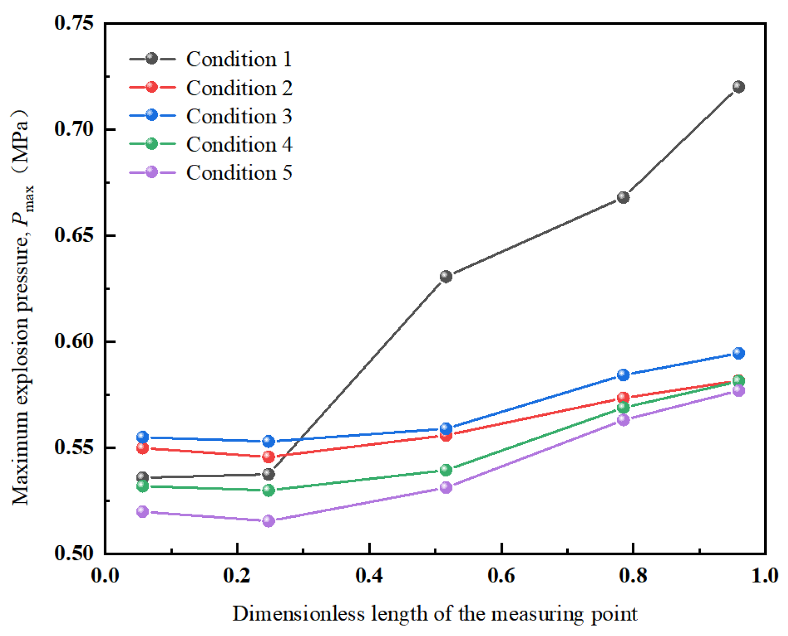
Figure 2 shows the relationship between the maximum explosion pressure (
Pmax) in each region and the dimensionless length of the measuring point under different working conditions, and
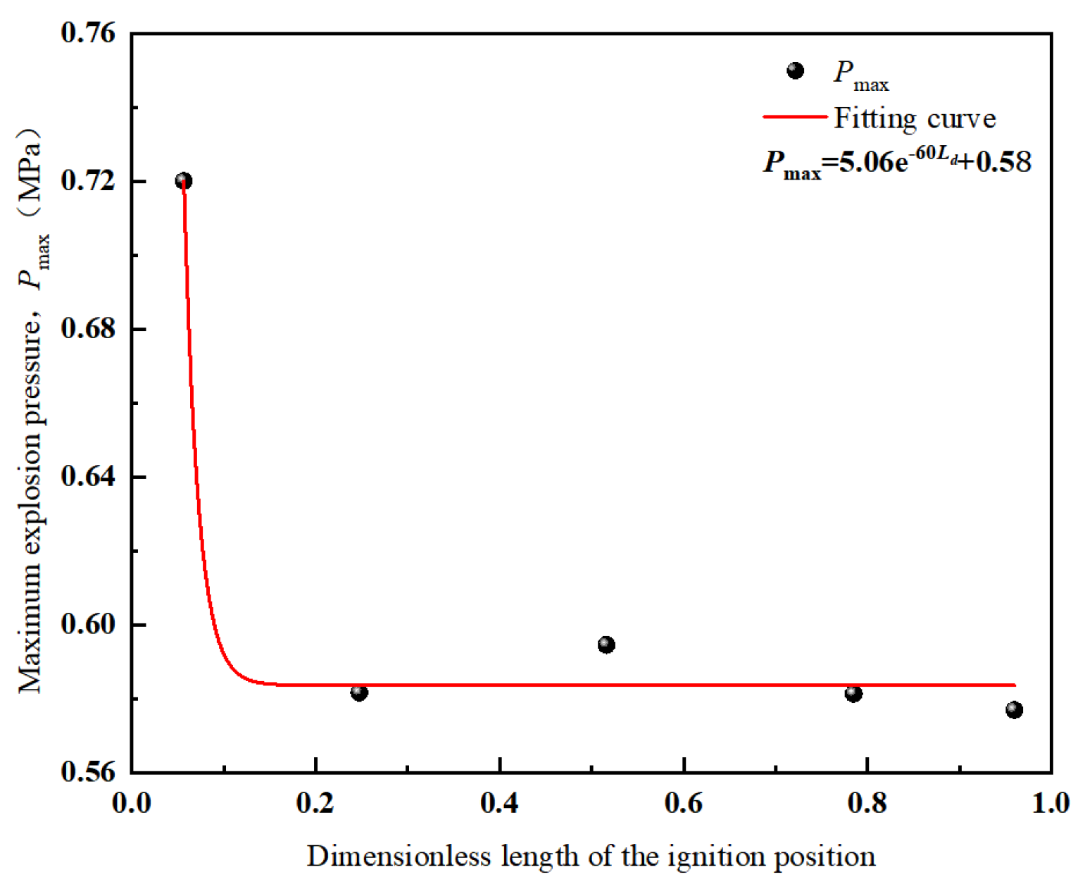
Figure 3 shows the relationship between the maximum pressure value of the linked vessels and the dimensionless length of the ignition position.
Under working condition 1, the flame propagates from the large vessel to the small vessel after being accelerated by the pipe. Due to the dual effects of physical compression and long-pipe acceleration, the maximum explosion pressure of 0.7202 MPa is formed in the linked vessels, which is much higher than that of other working conditions (0.5770–0.5946 MPa). Under all working conditions, the maximum explosion pressure is located in the small vessel (region 5), and the order of the pressure peaks in each region from large to small is: region 5 > 4 > 3 > 1 > 2. The closer the region is to the small vessel, the higher the pressure, which is due to the volume constraint of the small vessel and the superposition effect of the cyclic propagation of the explosion wave.
The dimensionless length of the ignition position has an exponential function relationship with the maximum explosion pressure (Formula (1)). As the ignition point moves from region 1 to region 5, the maximum pressure of the vessel shows an overall downward trend.
Table 4 shows the analysis of pressure peak parameters in each region under different working conditions, and the peak order of each working condition is defined according to the peak time.
Under all working conditions (i.e., regardless of the ignition position), Region 1 consistently attains the maximum explosion pressure the latest. This phenomenon is primarily attributed to the relatively large volume of Region 1 (corresponding to the main vessel), which leads to a weaker compressive effect during the explosion process and consequently results in a slower pressure rise rate. Specifically, under all operating conditions, Regions 3–5 reach the maximum pressure peak almost simultaneously, indicating that the flame shock wave propagates at an extremely high speed within this regional scope. Furthermore, for operating conditions 2–4 (ignition initiated within the pipe), the first pressure peak emerges in the pipe within 50–70 ms, with a pressure magnitude ranging from approximately 0.002 MPa to 0.040 MPa. This observation demonstrates that when ignition occurs inside the pipe, the combined effects of pipe wall constraints and flame acceleration within the pipe during the initial explosion stage induce distinct pressure fluctuations in the pipe.
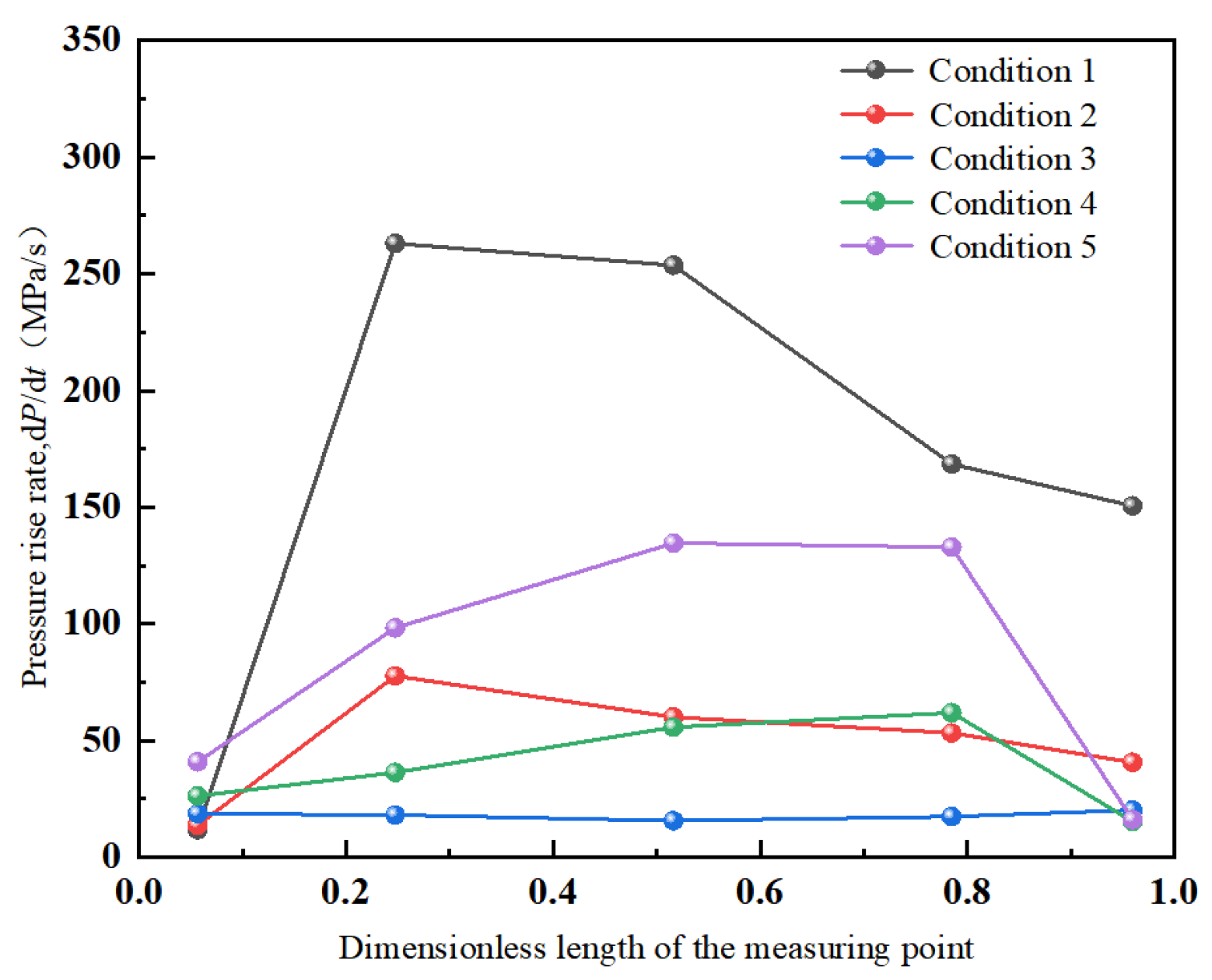
Figure 4 presents the variation of the maximum pressure rise rate (d
P/d
t)
max with the dimensionless length of the measuring point under different working conditions, and
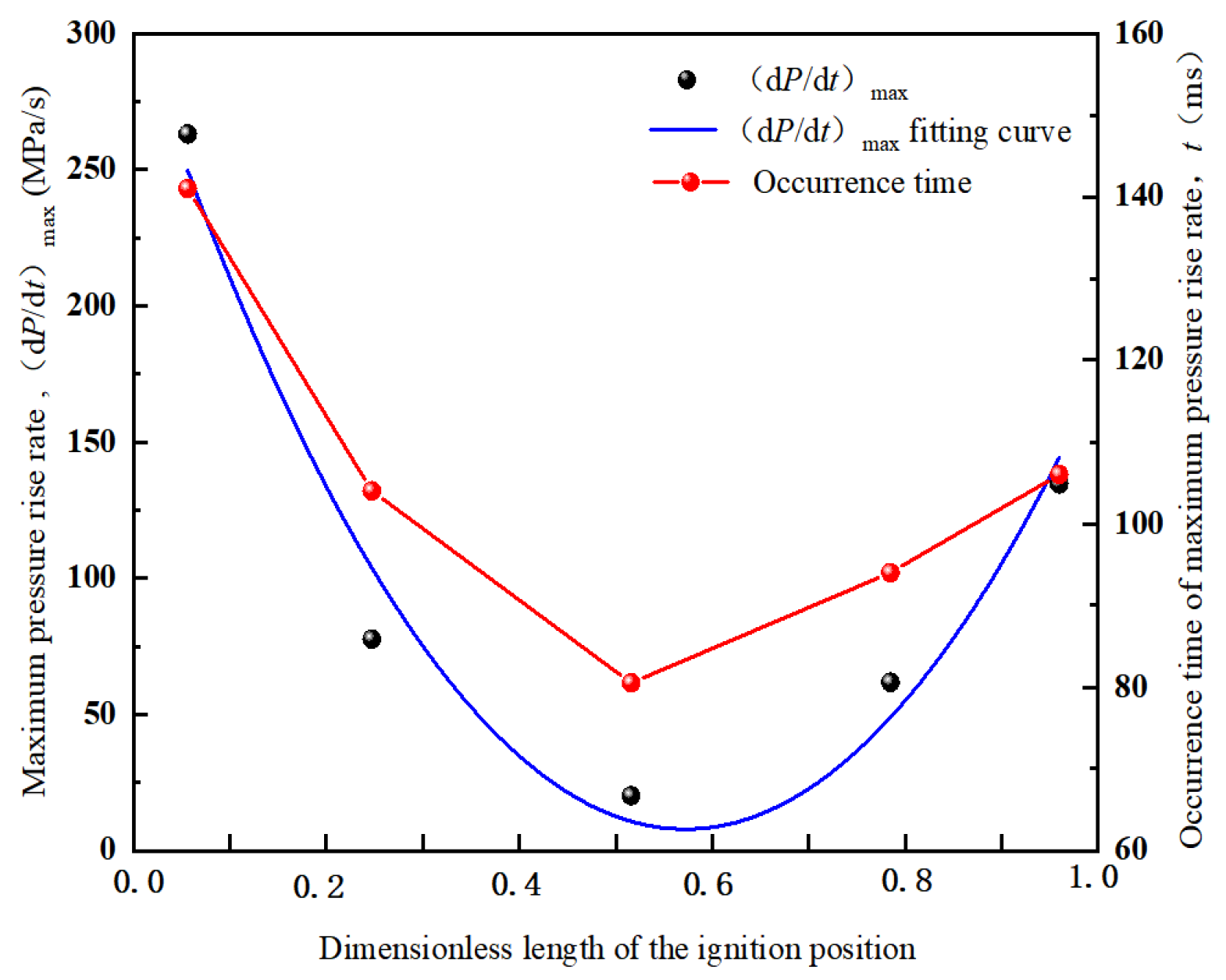
Figure 5 shows the relationship between the maximum pressure rise rate and its occurrence time in the vessel and the dimensionless length of the ignition position.
Under working conditions 1, 2, 4, and 5, the maximum pressure rise rate in each region first increases and then decreases with the dimensionless length of the measuring point, while it remains basically stable under working condition 3. Across all working conditions, the maximum pressure rise rate in Regions 1 and 5 is mostly maintained at 10–50 MPa/s, except for region 5 under working condition 1, where it approaches 100 MPa/s. This is attributed to the constraint effect of the vessel wall, which weakens the propagation intensity of high-turbulence gas. For all working conditions except working condition 3, the values in regions 2–5 are significantly higher (basically greater than 50 MPa/s), with a maximum of up to 270 MPa/s. This is because Region 1 has a large volume and the pipe exhibits a relief effect, whereas Regions 2–4 are slender pipes characterized by small cross-sectional area, long length, significant gas compression and pipe acceleration effects, and high turbulence intensity.
Under working condition 1, the pressure rise rate in the linked vessels is the highest. This is due to sustained flame acceleration in the pipe leading to enhanced turbulence under this condition, and the smaller volume of region 5 compared to region 1, where compression and backflow phenomena further intensify turbulence. Under working condition 3, the maximum pressure rise rate in the linked vessels is the lowest, approximately 1/10 of that under working conditions 1 and 5. This is because the shorter pipe results in insufficient time for the explosion wave to accelerate propagation, leading to lower turbulence intensity.
The maximum pressure rise rate in the linked vessels and its occurrence time show a trend of first decreasing and then increasing with the increase in the dimensionless length of the ignition position. Through fitting, the maximum pressure rise rate varies with the dimensionless length of the ignition position in a quadratic function relationship, as shown in Formula (2).
3.2. Explosion Temperature and Flame Propagation Speed
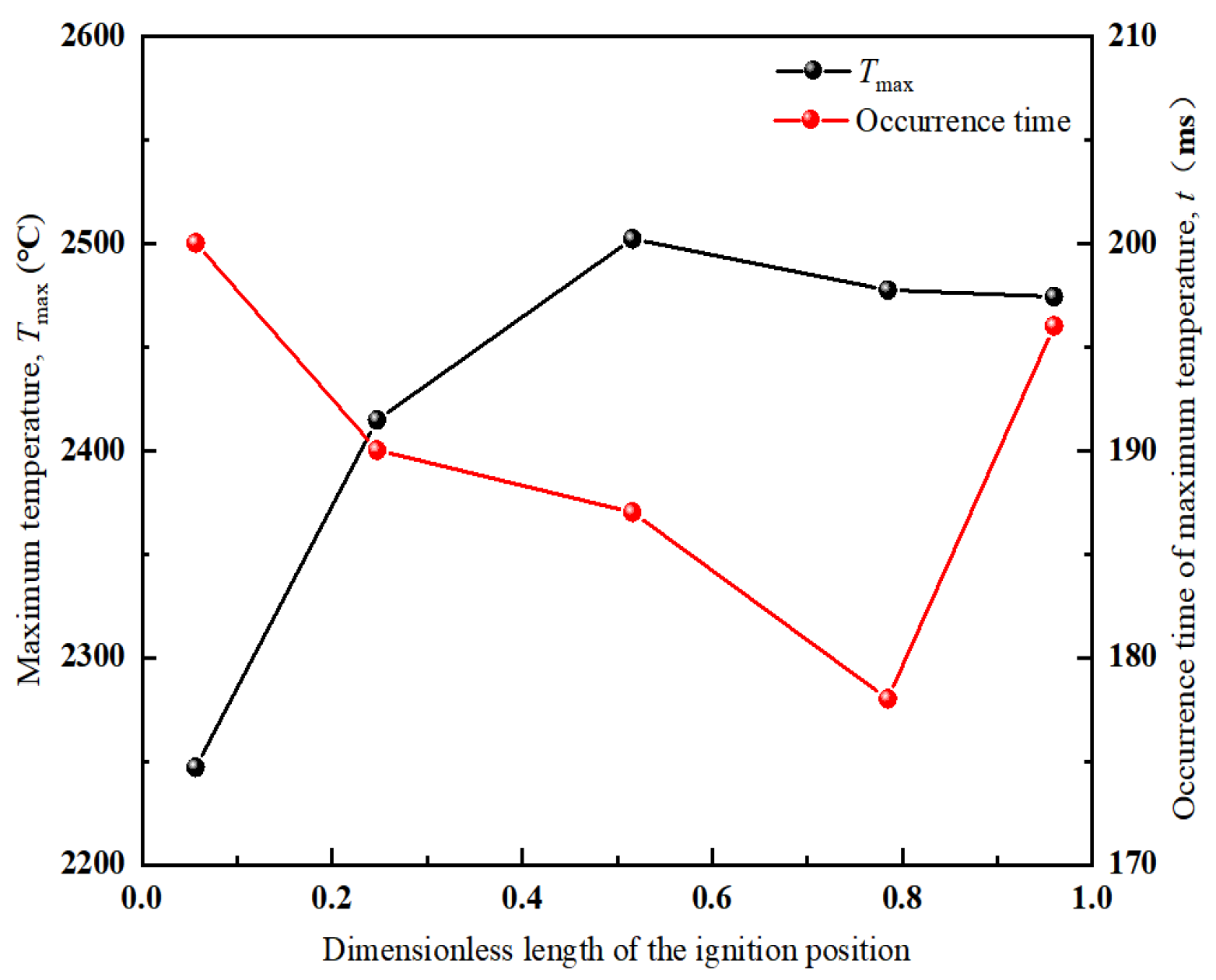
Figure 6 shows the variation of the maximum temperature (T
max) and its occurrence time in the linked vessels with the dimensionless length of the ignition position, and
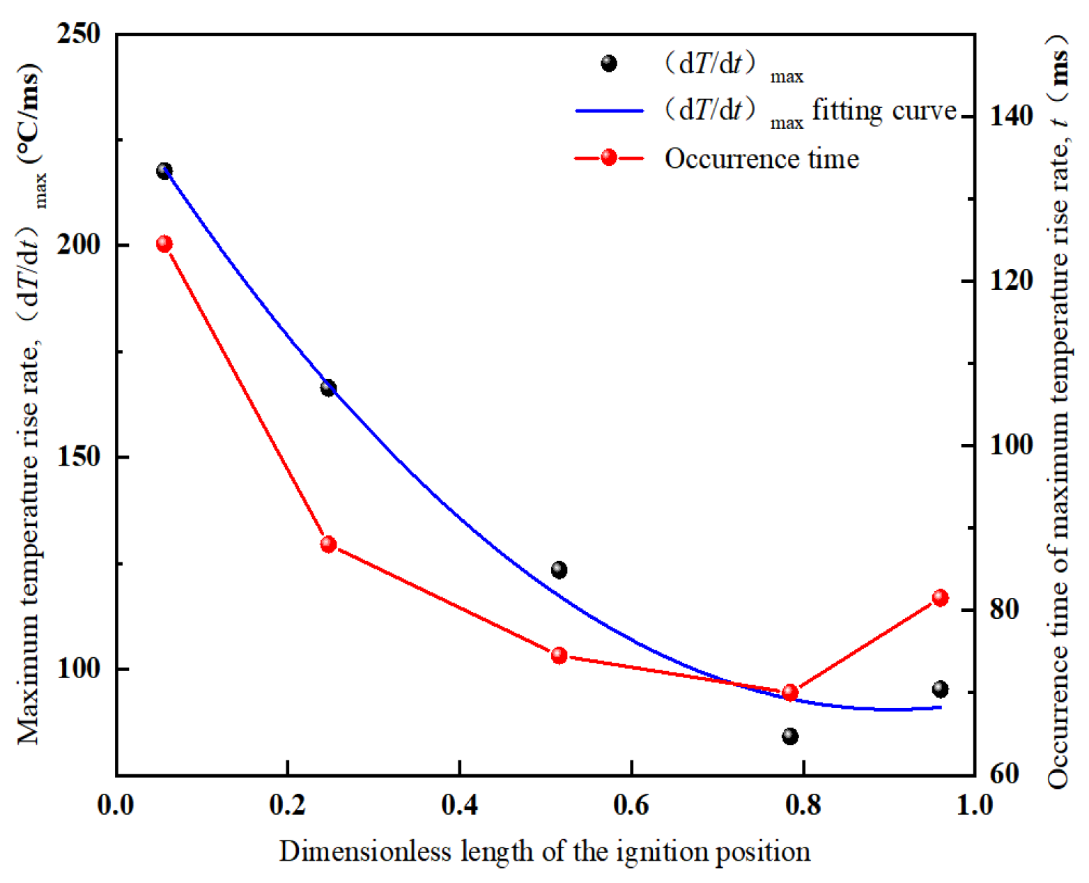
Figure 7 shows the variation of the maximum temperature rise rate (d
T/d
t)
max and its occurrence time in the linked vessels with the dimensionless length of the ignition position.
Under working condition 1, the temperature in region 1 rises slowly. The explosion flame propagates to the pipe and ignites the combustible gas in regions 2 and 3, where the temperature rises sharply, and then decreases after the flame continues to propagate forward; after regions 4 and 5 are ignited, violent explosion releases a lot of heat, making the temperature in these regions rise significantly; subsequently, the reflected high-temperature gas from the end vessel flows back, leading to a second rise in the temperature of regions 2 and 3.
Under working condition 2, the temperature changes in regions 1 and 5 are similar to those under working condition 1, but since the ignition position is located in the middle pipe, the flame forms in region 2 and propagates bidirectionally. The high-temperature gas circulates back and forth, causing temperature fluctuations in regions 2–4 and multiple peaks. The temperature change trends under working conditions 3 and 4 are consistent with those under working condition 2.
Under working condition 5, the flame propagates to the middle pipe, causing the temperature of regions 2–4 to rise. In the later stage, due to the pressure difference, the high-temperature gas propagates back and forth in the linked vessels, leading to fluctuations in the temperature of regions 2–4.
As the dimensionless length of the ignition position increases, the maximum temperature in the linked vessels shows a trend of first increasing and then slightly decreasing; however, the occurrence time of the maximum temperature exhibits the opposite trend. With the increase of the dimensionless length of the ignition position, the maximum temperature rise rate and its occurrence time first decrease and then increase, indicating that the chemical reaction is the most intense under working condition 1, which is consistent with the result that the pressure value is the largest under working condition 1. After fitting, the maximum temperature rise rate has a quadratic function relationship with the dimensionless length of the ignition position, and the function formula is shown in Formula (3).
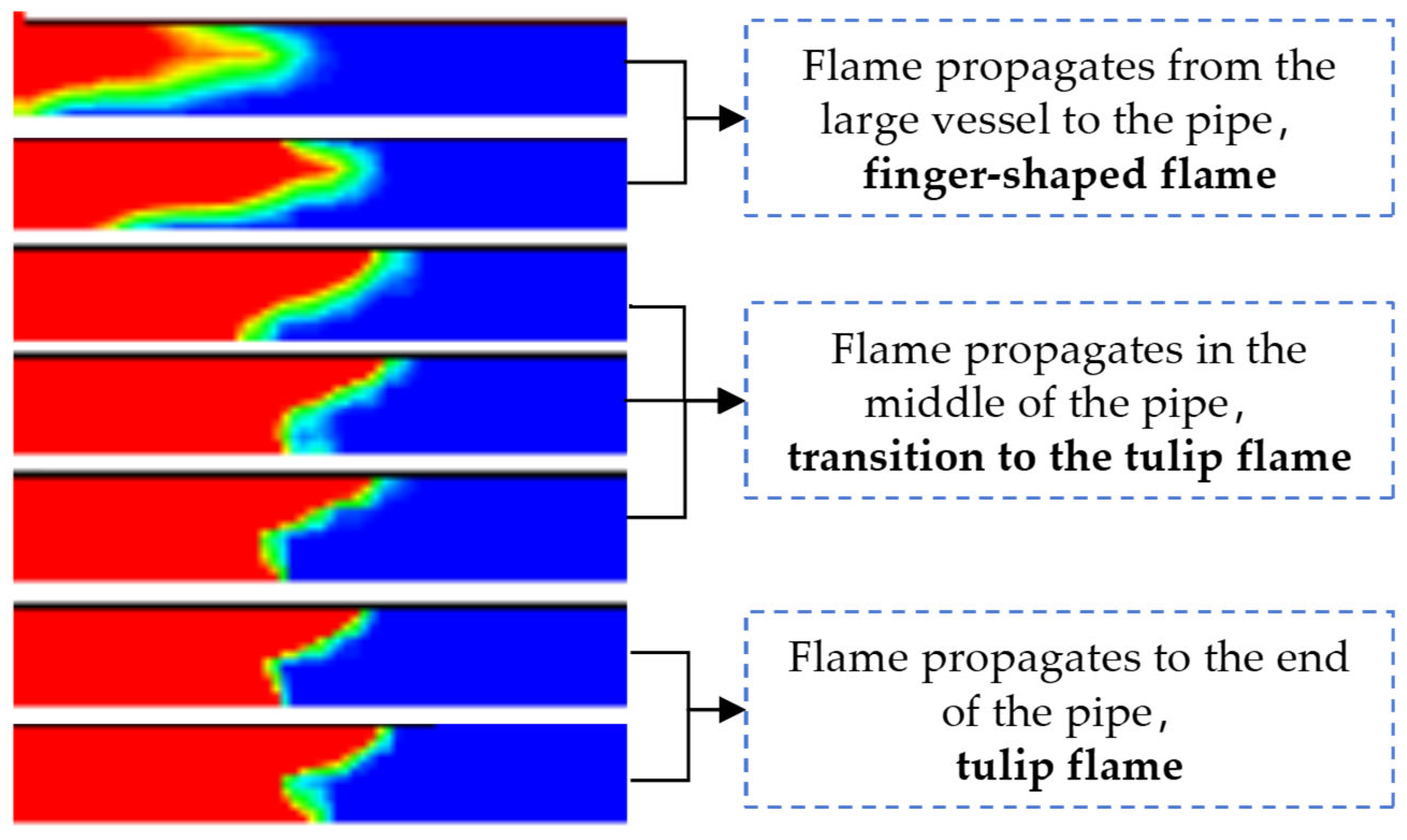
Figure 8 depicts the evolution of the flame front shape within the pipe. Initially, when the flame first propagates from the large vessel into the pipe, the flame front presents a finger shape; as it travels to the middle section of the pipe, the flame front transitions toward a tulip shape; by the time it reaches the end of the pipe, the flame front has fully formed a tulip shape.
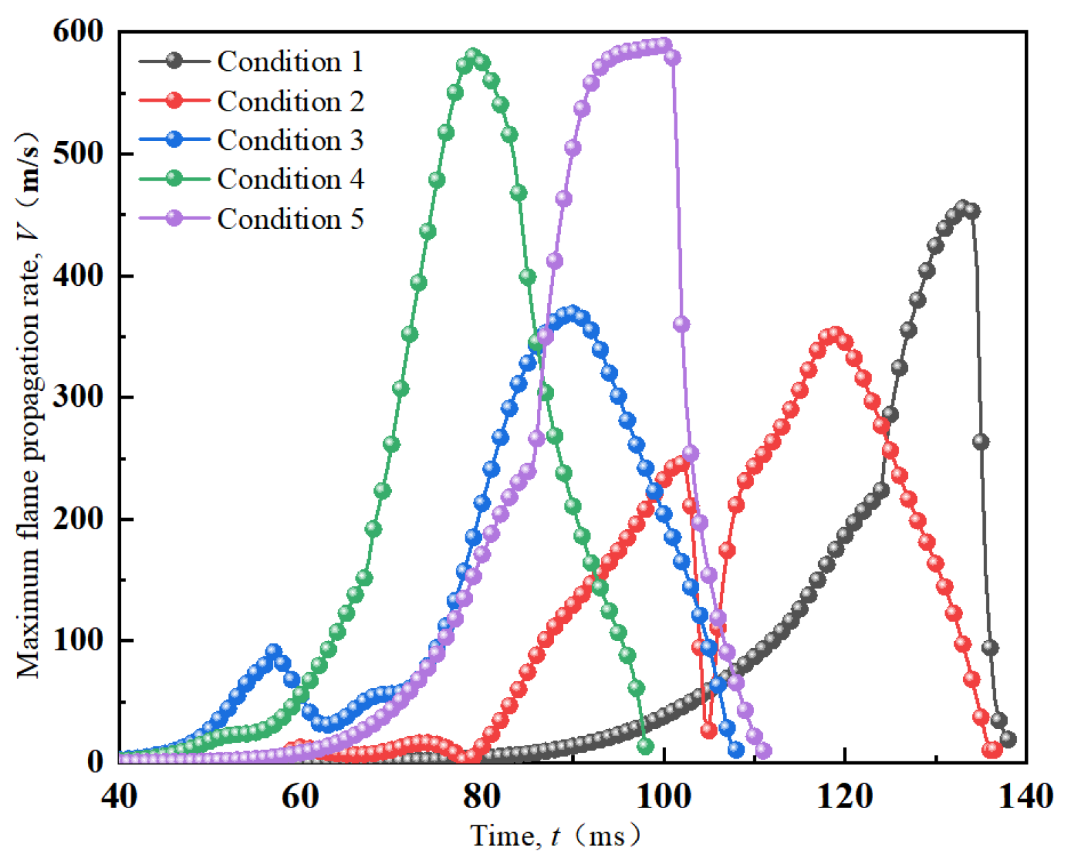
Figure 9 shows the variation curves of the maximum explosion flame propagation speed (
Vmax) in the linked vessels with time under different working conditions, and
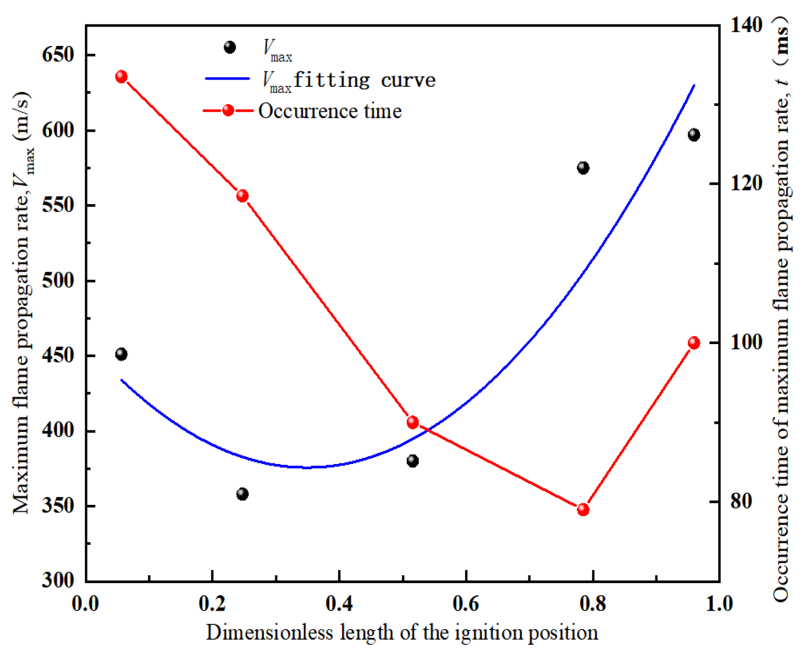
Figure 10 shows the variation of the maximum speed and its occurrence time in the linked vessels with the dimensionless length of the ignition position.
Under all working conditions, the pipe acceleration effect dominates the difference in flame propagation speed. The maximum speed in regions 1 and 5 is relatively low, at approximately 50 m/s, while the speed in regions 2–4 (pipe regions) is significantly higher, up to 300–600 m/s. Under working conditions 4 and 5, the maximum speed in the linked vessel is the largest, at approximately 600 m/s, followed by working condition 1, about 450 m/s, while it is smaller under working conditions 2 and 3, about 380 m/s. This is because when igniting near region 5, the gas has a large compressible space, and the pipe acceleration is greater.
The occurrence position of the speed peak shows regularity: under working condition 1, it is located in region 4; under other working conditions, it is located in region 2, both at the end of one side of the pipe. Under working condition 1, the shock wave-driven gas continues to accelerate through regions 2–4 and reaches the maximum speed in region 4. Under working conditions 2–4, the gas flows propagates bidirectionally, folds back after being constrained by the vessel walls at both ends, and accelerates for the second time through regions 2–4. Since the volume of region 5 is smaller than that of region 1, the gas flows faster towards region 1, and finally forms the speed peak in region 2. Under working condition 5, the shock wave-driven gas continues to accelerate through the space of regions 4, 3, and 2, and reaches the maximum speed in region 2.
With the increase of the dimensionless length of the ignition position, both the maximum flame propagation speed and its occurrence time in the linked vessels show a trend of first decreasing and then increasing. After fitting, the maximum flame propagation speed has a quadratic function relationship with the dimensionless length of the ignition position, and the function formula is Formula (4).
3.3. Mechanism Analysis
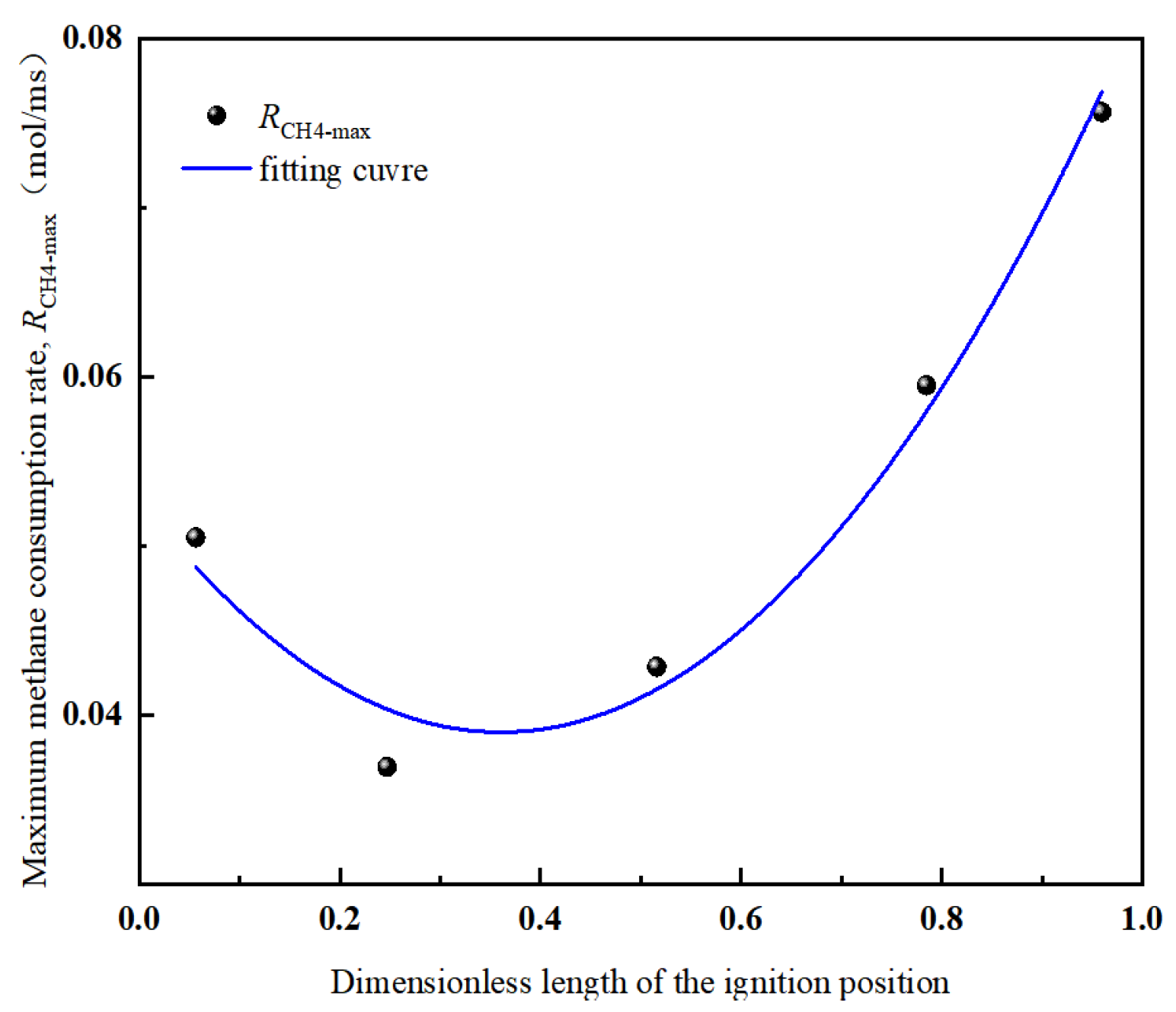
Through data analysis of methane consumption under each working condition, the variation curve of the maximum methane consumption rate (
RCH4-max) in the linked vessels with the dimensionless length of the ignition position is obtained, as shown in
Figure 11.
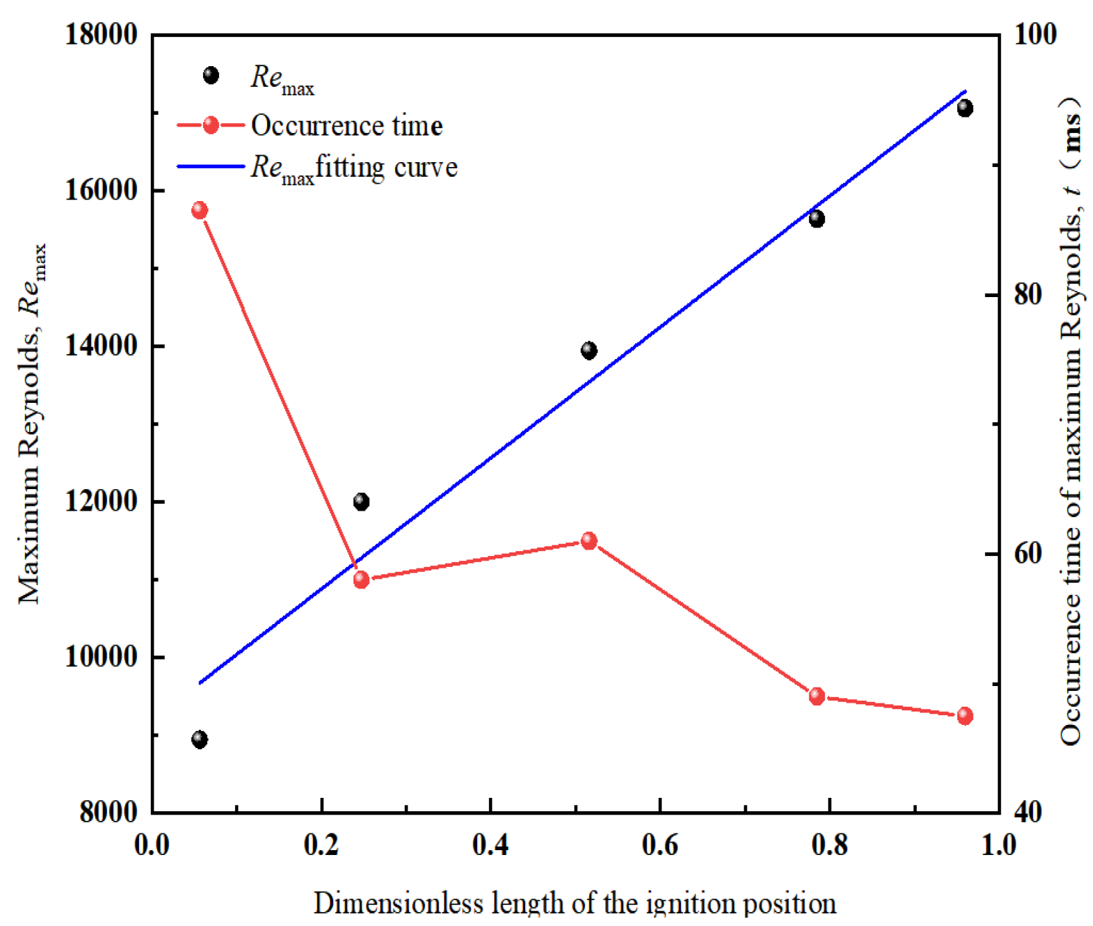
Figure 12 shows the variation curves of the maximum Reynolds number (
Remax) and its occurrence time under different working conditions with the dimensionless length of the ignition position.
With the increase of the dimensionless length of the ignition position, the maximum methane consumption rate first decreases and then increases. After fitting, the maximum methane consumption rate has a quadratic function relationship with the dimensionless length of the ignition position, as shown in Formula (5). The variation law of the maximum methane consumption rate is consistent with that of four explosion macro parameters: maximum explosion pressure, explosion pressure rise rate, temperature rise rate, and flame propagation speed, which supports the evolution characteristics of macro parameters. Moreover, under working condition 5, the methane consumption rate is the largest, that is, the explosion reaction rate under this working condition is the strongest, leading to a large pressure difference in the linked vessels. Therefore, it also supports the conclusion that the flame propagation speed is the largest under this working condition.
The variation of Reynolds number with time in the linked vessels under different working conditions is analyzed, and Reynolds number Re = 2300 is taken as the boundary between laminar combustion and turbulent combustion. For working conditions 1 to 5, the times when laminar combustion transitions to turbulent combustion are 65.5, 46.0, 45.0, 34.0, and 34.5 ms respectively, and the times when turbulent combustion is the most intense are 86.5, 60.0, 62.0, 49.0, and 47.5 ms respectively. Based on the variation of Reynolds number with time and combined with the flame front position at different times, it is comprehensively judged that under each working condition, the region near the wall in region 1 and regions 2–5 are turbulent combustion regions. The maximum Reynolds number changes linearly with the dimensionless length of the ignition position, and the function formula is Formula (6). The time to reach the maximum turbulence intensity in the linked vessels generally shows a decreasing trend with the increase of the dimensionless length of the ignition position.
Under working condition 5, not only the methane consumption rate is the largest, but also the flame front turbulence intensity reaches the maximum. The larger turbulence intensity will lead to the deformation of the flame front, thereby increasing the contact area with air, enhancing the reaction rate, and further increasing the flame propagation speed. This explains the explosion characteristic that the explosion flame propagation speed is the largest under this working condition.
3.4. Influence of Ignition Position on the Small Vessel
Based on the previous analysis, the small vessel (region 5) in the linked vessels shows the maximum explosion pressure peak when igniting at different positions, indicating that region 5 bears the greatest damage during the explosion.
Table 5 shows the changes of explosion parameters in region 5 under different working conditions. With the increase of the dimensionless length of the ignition position, the maximum explosion pressure value in region 5 shows a gradual decreasing trend. Under working condition 1, the maximum explosion pressure value in region 5 is much higher than that in other working conditions. This is because the large vessel has a large volume and high energy release from the combustible gas reaction. The high-turbulence flame is accelerated by the long pipe and injected into region 5, causing a violent explosion. The maximum pressure rise rate in region 5 shows a continuous decreasing trend with the increase of the dimensionless length of the ignition position, indicating that the turbulence intensity in region 5 is mainly derived from the continuous acceleration of the pipe, which is proportional to the pipe length through which the pressure wave propagates from the ignition position. The temperature rise rate also shows a similar change trend to the explosion pressure rise rate, and both the temperature rise rate and the explosion pressure rise rate decrease continuously with the increase of the dimensionless length of the ignition position. Under all working conditions, the maximum flame propagation speed in region 5 is small, only about 10 m/s, which indicates that the ignition position has little influence on the maximum speed in region 5.
4. Conclusions
This paper investigates the effect of ignition location on the explosion characteristics in linked vessels with concentration gradients. The main conclusions of this study are as follows:
(1) Regardless of the ignition position, the maximum explosion pressure is consistently located in the small vessel (core pressure risk zone), and the maximum explosion pressure decreases overall as the ignition position moves closer to the small vessel. Ignition in the large vessel results in significantly higher explosion pressure than other positions.
(2) The maximum pressure rise rate, maximum temperature rise rate, maximum flame propagation speed, and maximum methane consumption rate all exhibit a trend of first decreasing and then increasing with the movement of the ignition position from the large vessel to the small vessel.
(3) The pipe acceleration effect dominates flame propagation: the maximum flame speed (up to 600 m/s) always occurs at the pipe ends, with the highest speed observed when igniting near the small vessel.
(4) Turbulence intensity (Reynolds number) increases linearly with the ignition position’s proximity to the small vessel, peaking at the small vessel ignition.
Based on the research in this paper, the following suggestions for the engineering applications of explosion prevention and mitigation are proposed:
(1) Prioritize strengthening the protection of small vessels to mitigate the risks of vessel rupture and pressure accumulation.
(2) Install flame arresters and shock wave absorbers in the middle of the connecting pipe to suppress flame acceleration and shock wave propagation.
To further improve the theoretical system of explosion evolution in linked vessels with concentration gradients and enhance the applicability of engineering practices, future research can focus on the following directions:
(1) Explore the differences in explosion characteristics between forward (large vessel → small vessel) and reverse (small vessel → large vessel) flame propagation;
(2) Investigate the scale effect (including the volume ratio of vessels, pipe length/cross-sectional area, etc.) and establish a scalable prediction model suitable for industrial equipment of different sizes;
(3) Develop explosion venting technology targeted at linked vessels with concentration gradients.