Article

Research on Temperature Distribution of Cable Fire in Utility Tunnel and Fire Extinguishing Efficiency of High-Pressure Water Mist Fire Extinguishing System

Institute of Building Fire Research, China Academy of Building Research, Beijing 100013, China
*
Author to whom correspondence should be addressed.
Fire 2025, 8(10), 404; https://doi.org/10.3390/fire8100404
Submission received: 8 September 2025 / Revised: 9 October 2025 / Accepted: 13 October 2025 / Published: 17 October 2025
(This article belongs to the Special Issue Confined Space Fire Safety and Alternative Fuel Fire Safety)

Abstract

Utility tunnels concentrate various important urban engineering pipelines within a shared underground space, which poses significant fire risks, particularly from cable fires. In this study, a full-scale fire experiment was conducted to investigate the temperature distribution characteristics of cable fires in utility tunnels, along with the effects of spray intensity, cable fullness, and longitudinal ventilation on the extinguishing efficiency of a high-pressure water mist fire extinguishing system (HWMFES). The results show that the maximum heating area of a cable fire in a utility tunnel is localized to the three cable trays nearest to and directly above the fire source, with a peak temperature of 825 °C, while the impact on other areas is negligible. Increasing the spray intensity from 0.7 to 1.0 L/(min·m2) reduced the time required to lower temperatures to 50 °C by 40.8%, while reducing cable fullness from 12 to 6 cables per tray shortened extinguishing time by 22.5%. Additionally, applying a ventilation speed of 2 m/s enhanced cooling efficiency, reducing the time to reach 50 °C by 67.5% compared to still air conditions. These findings provide practical insights and data support for optimizing the design and application of HWMFES in enhancing fire safety in utility tunnels.

1. Introduction

As an intensive infrastructure, the utility tunnel concentrates various important urban engineering pipelines such as communication cables, power cables, gas pipelines, and water supply and drainage pipelines within a shared underground space. While enhancing urban transportation power, these utility tunnels also face increasingly severe fire risks and safety threats [1,2,3,4,5]. According to fire accident statistics, power cable fires are one of the more likely types of fires to occur in utility tunnels. Causes such as cable overloading, poor electrical contact, insulation aging, and external fire spread can easily ignite cables, leading to substantial economic losses and serious social impacts [6,7,8,9,10]. Recent research by Seo et al. [6] further quantified the fire risk of cables in utility tunnels through experimental studies, identifying key evaluation factors such as heat release rate (HRR) and smoke production rate. Their work provides a fundamental basis for assessing cable fire hazards and aligns with the necessity of developing effective suppression strategies.
The strategic application of longitudinal ventilation is a cornerstone in managing tunnel fire dynamics, primarily aimed at controlling smoke flow and ensuring a tenable environment for evacuation [11,12]. Extensive research has been conducted on the effects of ventilation velocity on critical safety parameters like critical velocity, heat release rate (HRR), and ceiling temperature [11,13]. As highlighted by Khattri et al. [11], increasing ventilation velocity can accelerate fire growth and exacerbate these parameters under critical conditions. Building upon this established knowledge, recent innovative studies have begun exploring more fundamental interventions, such as modulating the oxygen content of the ventilation air itself. Khattri et al. [11] demonstrated that reducing the oxygen concentration below 18% can significantly suppress maximum heat release rates, ceiling temperatures, and fire growth rates, while maintaining a survivable environment. This presents a paradigm shift from simply managing smoke to actively controlling combustion chemistry.
In parallel to ventilation strategies, the selection of fire suppression systems is crucial. Water mist fire extinguishing system (WMFES) has become the preferred solution for fire control in utility tunnels due to its environmental friendliness, electrical insulation properties, high fire extinguishing efficiency, and ability to minimize secondary equipment damage [14,15,16,17,18]. The design and performance of WMFES are governed by international standards such as NFPA 750 [18], which provides a framework for system classification and application. However, the performance of WMFES in utility tunnels is affected by multiple factors [14,15,16,19,20,21,22]. For instance, Jia et al. [9] examined the influence of flow coefficient, nozzle spacing and nozzle pressure on the fire extinguishing efficiency of low-pressure WMFES. The results indicated that low-pressure WMFES can extinguish cable fires in utility tunnels quickly and effectively. Increasing nozzle pressure and flow coefficient significantly improve extinguishing performance, while the nozzle spacing has a comparatively smaller effect. Zhu et al. [14] evaluated the performance of HWMFES in a tunnel with longitudinal ventilation, demonstrating its efficacy in reducing overall ambient temperatures. Specifically, their results indicated that increasing nozzle pressure (and thereby the spray intensity) significantly improves the cooling effectiveness of the HWMFES under constant fire source power and fixed nozzle positions and flow coefficient. Furthermore, the combined application of HWMFES and a mechanical smoke extraction system can further lower the ambient temperature inside the tunnel. Sun et al. [19] examined the effects of nozzle pressure and ventilation velocity on smoke blocking and cooling effectiveness in a reduced-scale tunnel experiment. The results showed that higher nozzle pressure improved the cooling performance, while a longitudinal ventilation velocity of 0.8 m/s reduced the effectiveness of the water spray system in blocking smoke diffusion. An investigation by Li et al. [22] into a segmented water mist system demonstrated its efficacy in blocking fire-induced smoke and heat, identifying nozzle count, nozzle pressure, heat release rate, and distance to the fire source as key factors influencing its smoke containment efficiency.
Despite water mist fire extinguishing systems (WMFES) have demonstrated effectiveness in utility tunnel fire scenarios through prior research and practical applications, significant uncertainties persist concerning their optimal extinguishing efficiency and key design parameters. As specified in the Technical Code for Water Mist Fire Extinguishing Systems (GB 50898-2013) [17], the design of an open system that employs a fully submerged application method, including nozzle spacing, spray intensity, nozzle pressure, and installation height, should be validated through full-scale fire testing. Although the code permits the determination of minimum spray intensity and nozzle spacing based on installation height, it offers no specific guidance for the design of cable cabins in utility tunnels [17]. Moreover, the Standard for Urban Utility Tunnel Engineering (GB/T 50838-2015) requires automatic shutdown of ventilation systems in the fire-affected and adjacent compartments during a fire incident [5]. Nevertheless, actual fire scenarios may involve unintended airflow due to compromised fire doors or environmental wind, which can influence WMFES performance. The layered configuration of cable trays and variations in cable fullness also considerably affect fire development and suppression outcomes [23,24]. Consequently, a systematic investigation of these factors is essential to advance the application of WMFES in such environments.
In line with the National Fire Protection Association (NFPA) 750 standard, WMFES are classified into low-pressure, medium-pressure, and high-pressure systems [18]. This study employed full-scale fire experiments to analyze temperature distribution patterns in utility tunnel cable fires and examine the effects of spray intensity, cable fullness, and longitudinal ventilation on the extinguishing efficacy of HWMFES. The findings of this research are intended to support the engineering design and implementation of HWMFES in utility tunnels.

2. Experimental Setup

2.1. Utility Tunnel Platform

The experiments were conducted in a full-scale utility tunnel at a research and development base. The tunnel measures 95 m in length, 3.4 m in width, and 2.9 m in height. Cable trays with a width of 750 mm were installed on both sides of the tunnel. A seven-layer cable tray system was mounted on one side of the tunnel. The vertical spacing between adjacent layers was 350 mm, with the lowest tray layer installed 300 mm above the tunnel floor. Depending on the test conditions, each layer on this side was loaded with either six or twelve 10 kV flame-retardant cables. The opposite side was equipped with a six-layer cable tray system, featuring a larger inter-layer spacing of 400 mm. The lowest tray layer of this system was also positioned 300 mm above the floor. Each layer on this side carried three 110 kV flame-retardant cables. The on-site layout of the full-scale utility tunnel is presented in Figure 1.

2.2. HWMFES

The HWMFES employed a total-flooding application method. The utility tunnel was divided into four zones, labeled Section A through D, with lengths of 25 m, 25 m, 25 m, and 20 m, respectively. Nozzles were mounted vertically downward along the centerline of the tunnel ceiling, at a spacing of 3.0 m and a nozzle pressure of 10.0 MPa. Open-type nozzles with flow coefficients of K = 1.0 and K = 0.7 were selected in turn to investigate the fire extinguishing effectiveness the HWMFES and its cooling rate of under spray intensities of 1.0 L/(min·m2) and 0.7 L/(min·m2), respectively. The utility tunnel zoning and the nozzles layout are illustrated in Figure 2.

2.3. Fire Source

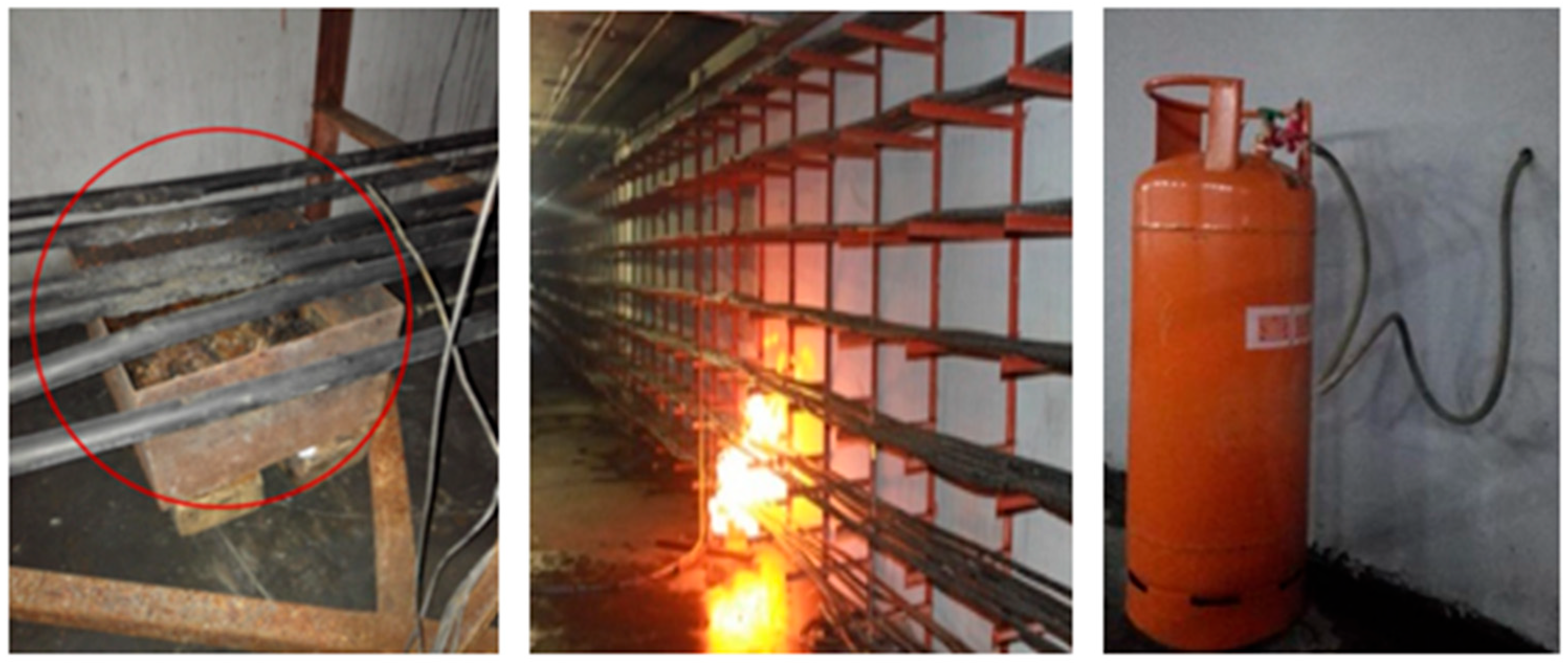
The fire source was configured according to the standardized method specified in The Technical Code for Water Mist Fire Extinguishing Systems (GB 50898-2013) [17]. A propane burner with a HRR of (250 ± 25) kW was employed to ignite the cables. The fire source was positioned under the lowest tray layer on the side with the seven-layer cable tray, specifically in the middle of Zone B, and located between two water mist nozzles as recommended. The fire source layout and the propane burner are provided in Figure 3.
The use of a standardized propane burner ensures consistency with national testing codes and allows for reproducible comparison between test conditions. However, it is acknowledged that this method may not fully capture the complex pyrolysis, flame spread, and potential re-ignition behavior of a real cable fire, which represents a limitation of the standardized test method.

2.4. Ventilation System

In accordance with the Technical Code for Water Mist Fire Extinguishing Systems (GB50898-2013), full-scale fire experiments for WMFES in cable tunnels and basements should be conducted under controlled longitudinal ventilation. The code stipulates that ventilation speed must be measured and adjusted prior to testing, with the measurement point situated at the center of the tunnel’s pedestrian pathway and the ventilation speed at the measuring point should not be less than 1 m/s [17]. Additionally, for open systems operating in local application mode, the ventilation speed around the protected object should not exceed 3 m/s [17]. In line with these specifications, a movable ventilation fan was installed in the utility tunnel for this study to conduct HWMFES fire extinguishing experiments at a ventilation speed of 2 m/s. Figure 4 shows the ventilation fan layout within the utility tunnel.

2.5. Instrumentation

2.5.1. Temperature Measurement

K-type armored nickel–chromium/nickel–silicon thermocouples with a measurement range of 0 °C to 1300 °C and a data acquisition interval of 1 s were employed for temperature measurement.
The thermocouples were deployed in three groups to monitor the spatial temperature distribution during cable fires: directly above the fire source, on the fire source side, and on the opposite side. The specific arrangements were as follows:
  • Directly above the fire source
One thermocouple was installed on each cable tray layer directly above the fire source. They were labeled sequentially from the bottom (1st layer) to the top (7th layer) as Position 1 to Position 7.
  • On the fire source side
Thermocouples were installed on the 2nd (lower), 4th (middle), and 6th (upper) tray layers on the fire source side. They were positioned at six cross-sections along the tunnel: 2.5 m, 5.0 m, and 10.0 m from the fire source towards both Zone A and Zone C. The positions were sequentially labeled from the Zone A side to the Zone C side as: A10 (Lower, Middle, Upper), A5 (Lower, Middle, Upper), A2.5 (Lower, Middle, Upper), C2.5 (Lower, Middle, Upper), C5 (Lower, Middle, Upper), and C10 (Lower, Middle, Upper).
  • On the fire source opposite side
Thermocouples were installed on the 2nd (bottom), 4th (middle), and 6th (top) tray layers on the side opposite to the fire source. They were located at the same cross-sections as points A5, A2.5, the fire source, C2.5, and C5 on the fire source side. The positions were sequentially labeled as A (Bottom, Middle, Top), B (Bottom, Middle, Top), C (Bottom, Middle, Top), D (Bottom, Middle, Top), and E (Bottom, Middle, Top).

2.5.2. Ventilation Speed Measurement

An array anemometer with a range of 0–5 m/s and an accuracy of 0.01 m/s was employed to measure the ventilation speed inside the utility tunnel.
The anemometer sensors were arranged at the fire source cross-section. Five measurement points were aligned vertically along the tunnel centerline with a spacing of 0.5 m between them. The lowest point was positioned 0.4 m above the tunnel floor.
The layout of measurement points is shown in Figure 5.

2.6. Test Method

Five test conditions were designed, as summarized in Table 1. The ventilation fan was not activated for Test Conditions 1 through 4. For Test Condition 5, the fan was activated to maintain an average ventilation speed of 2 m/s at the center of the fire source cross-section.
  • Test Condition 1 served as a baseline. Twelve flame-retardant cables were laid on each tray layer on the fire source side, and the HWMFES was not activated. This condition aimed to investigate the natural temperature distribution characteristics of cable fires within the utility tunnel.
  • Test Conditions 2 and 3 were designed with twelve flame-retardant cables per layer on the fire source side. The HWMFES was activated at spray intensities of 0.7 L/(min·m2) and 1.0 L/(min·m2), respectively, to compare the effect of this parameter on the extinguishing effectiveness of the HWMFES.
  • Test Condition 4 differed from Test Condition 2 only in the number of cables on the fire source side, which was reduced to six per layer. This comparison evaluated the influence of cable fullness on the HWMFES ‘s performance.
  • Test Condition 5 was conducted under the same cable configuration as Test Condition 4 (six cables per layer) but with the fan activated to create a 2 m/s ventilation speed. This condition examined the effect of longitudinal ventilation on the fire extinguishing performance of the HWMFES.
In all fire extinguishing tests, only the nozzles in Zone B were activated.
Given the significant resource intensity of full-scale fire testing, each condition was conducted once. While every effort was made to ensure experimental control and instrument accuracy, the lack of repeated trials is acknowledged as a limitation. The results should be interpreted as demonstrating definitive trends and providing quantitative data for engineering design, with the understanding that some operational variability may exist.

3. Results and Discussion

3.1. Temperature Distribution Characteristics of Cable Fire in the Utility Tunnel

In Test Condition 1, which served as the baseline scenario without HWMFES activation, twelve 10 kV flame-retardant cables were loaded in each tray layer on the fire source side, while three 110 kV flame-retardant cables were placed on each tray layer on the opposite side. The experiment commenced at 0 s. The propane burner was ignited at 10 s to initiate the cable fire and deactivated at 150 s. The HWMFES was subsequently activated at 450 s to extinguish any residual flames. Figure 6 illustrates the temporal variation in temperature measured on different tray layers directly above the fire source.
As depicted in Figure 6, following ignition, temperatures at all vertical positions directly above the fire source increased markedly. The most rapid temperature rise occurred at Positions 1, 2, and 3, corresponding to the lower tray layers. The thermocouple at Position 1 attained a peak temperature of approximately 670 °C at 75 s, stabilizing thereafter. Position 2 reached a maximum temperature of 809 °C at 60 s, followed by a discernible decline. This decline is attributable to the second tray layer becoming fully engulfed by flames, placing the thermocouple within the flame zone itself. Notably, the thermocouple at Position 3 recorded the highest temperature of 825 °C as early as 50 s, maintained this plateau for 40 s, and then exhibited a significant drop commencing at 90 s. This 30 s delay in the temperature decline at Position 3 compared to Position 2 aligns precisely with the observed fire development timeline, where in the fire progressed from fully engulfing the second-layer cables to completely covering the third-layer cables. This pattern of fire spread and associated temperature evolution is consistent with the findings are consistent with the conclusion reported by Jia et al. [9], who also observed sequential vertical fire development in cable tray configurations within utility tunnels. Following the deactivation of the propane burner at 150 s, temperatures at all positions, except Position 3, decreased to a range of 100–250 °C in 300 s, and remained relatively stable. This observation suggests that the flame-retardant properties of the cables can, to a certain extent, inhibit fire propagation even in the absence of active fire suppression, a finding that corroborates the analysis of flame-retardant cable combustion characteristics by Zheng et al. [10].
Figure 7 presents the temporal changes in spatial temperature at different heights and cross-sections on the same side as the fire source but at varying longitudinal distances. As shown in Figure 7, although the maximum temperature directly above the fire source reached 825 °C before 150 s, the thermal impact on various points on the same side as the fire source was negligible. The thermocouples located at the uppermost positions nearest to the fire source, specifically “A 2.5 upper” and “C 2.5 upper”, experienced the most noticeable heating effect, yet their peak temperatures remained below 26 °C, representing an increase in only 2–3 °C above the ambient temperature. This observation demonstrates that the flame-retardant properties of the cables significantly inhibited the longitudinal propagation of fire along the cable trays.
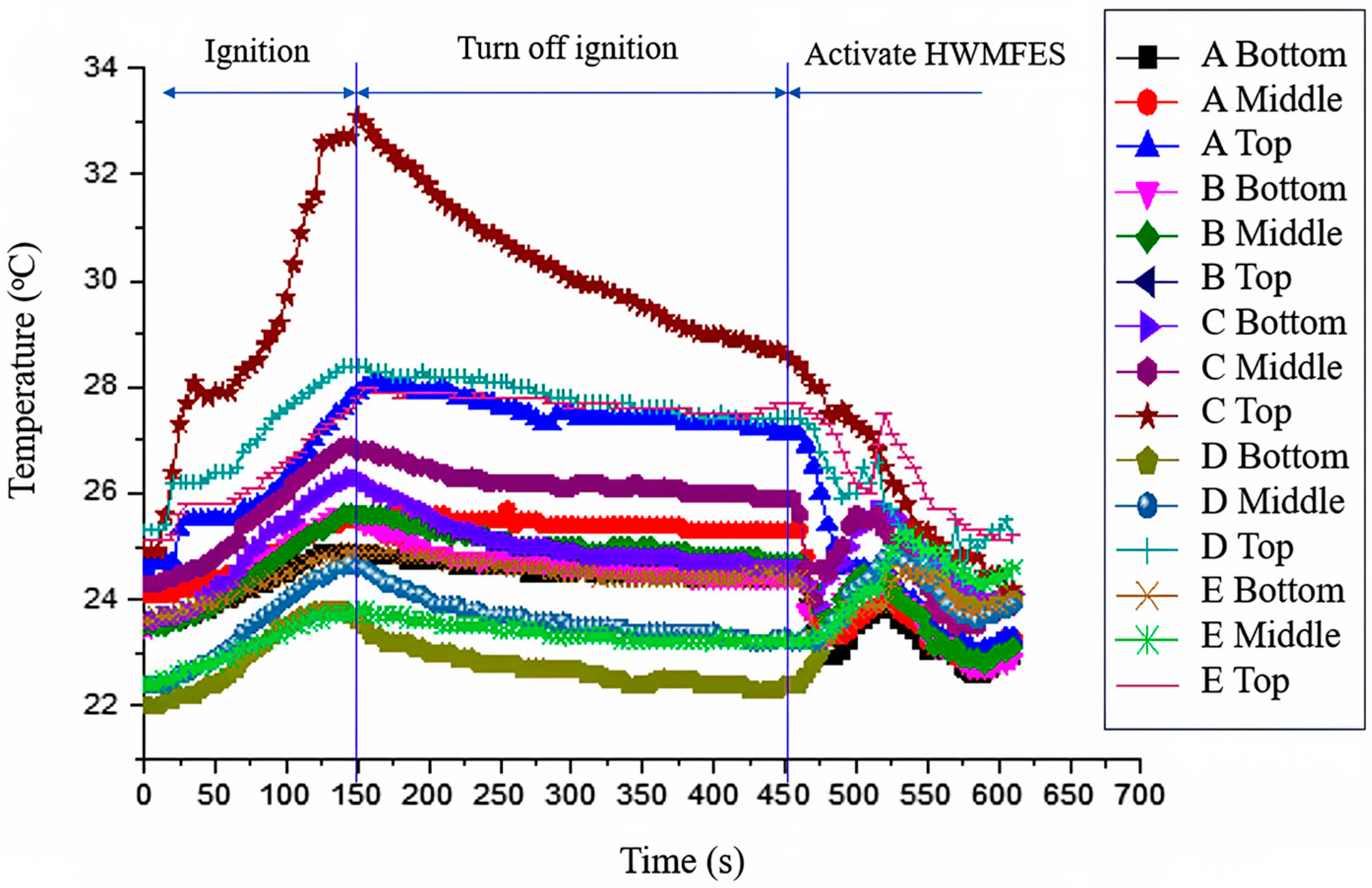
Figure 8 illustrates the temporal evolution of spatial temperature at different heights and cross-sections on the opposite side of the fire source. As observed from Figure 8, after ignition, only the temperature at “C Top” exhibited a noticeable increase, peaking at approximately 33 °C around 140 s. The thermal influence on other locations remained negligible, with temperature rises in only 2–3 °C above ambient levels. This indicates that the heat and smoke generated by the fire source were insufficient to cause significant damage to the area opposite the fire source. Following the deactivation of the propane burner at 140 s, the temperature at “C Top” showed a gradual decreasing trend, which can be attributed to the settling and gradual dissipation of the accumulated smoke, while temperatures at other locations remained unchanged. These results clearly demonstrate that the area most vulnerable to thermal impact on the opposite side is the upper tray layer within the same cross-section as the fire source. Therefore, this region should be considered a key area requiring enhanced fire resistance design in utility tunnels.

3.2. Influence of Spray Intensity on Fire Extinguishing Effect of HWMFES

Experiments 2 and 3 were conducted using twelve 10 kV flame-retardant cables in each tray on the fire source side and three 110 kV flame-retardant cables in each layer on the opposite side. The spray intensities for Test Conditions 2 and 3 were set at 0.7 L/(min·m2) and 1.0 L/(min·m2), respectively. The propane burner was activated at 10 s and 20 s after test initiation for Test conditions 2 and 3, respectively, and was shut down at 150 s and 160 s, resulting in a consistent ignition duration of 140 s for both Test conditions. HWMFES was immediately activated after the ignition period.
Figure 9 and Figure 10 present the temporal variations in spatial temperature directly above the fire source for the two test conditions, respectively. As observed in the figures, the peak temperature recorded during the ignition phase surpassed 830 °C under both test conditions. After HWMFES activation, temperatures at most locations experienced a brief period of fluctuation followed by a continuous decrease, except for Position 2 in Test condition 3, which exhibited a relatively stable temperature drop with minimal fluctuation.
The key finding pertains to the enhanced cooling efficiency achieved with higher spray intensity. For Test Condition 2 (0.7 L/(min·m2)), the time required to reduce temperatures at all measured positions to 100 °C was 170 s. In comparison, Test Condition 3 (1.0 L/(min·m2)) achieved the same temperature threshold in only 105 s, representing a 38.2% reduction in extinguishing time. The average cooling rates during the active extinguishing phase demonstrated even more significant improvement: 3.7 °C/s for the 0.7 L/(min·m2) condition versus 6.95 °C/s for the 1.0 L/(min·m2) condition. This corresponds to an 87.8% improvement in cooling efficiency, substantially enhancing the overall fire suppression performance.
The superior performance observed at higher spray intensity can be attributed to fundamental improvements in HWMFES extinguishing mechanisms. The core principle involves atomizing water into a dense cloud of micron-sized droplets under high pressure [25]. This finding is consistent with the global academic understanding of water mist mechanics. For instance, Blanchard et al. [26] conducted an experimental and numerical study on water mist-fire interaction in a tunnel, confirming that a dense mist cloud significantly enhances heat absorption through droplet evaporation and radiative attenuation. Their computational fluid dynamics (CFD) simulations quantified that nearly 73% of the heat absorbed by droplets came from convective heat transfer with hot gases, a mechanism that is optimized with finer droplet distributions achieved at higher pressures and intensities, directly supporting our observed enhancement in cooling efficiency. At the elevated intensity of 1.0 L/(min·m2), the system generates a larger volume of finer droplets [14,19], significantly increasing the total water surface area exposed to the flame. This enhanced surface area facilitates more efficient heat absorption through rapid droplet evaporation. As the mist vaporizes, it absorbs substantial latent heat and expands in volume, producing large amounts of steam that effectively dilute the surrounding oxygen concentration and inert the flame plume. Additionally, the denser mist cloud formed at higher spray intensity provides more effective radiant heat attenuation. The observed enhancement in cooling efficiency with increased spray intensity is consistent with the core principles outlined in NFPA 750 [18], which emphasizes the importance of adequate water mist discharge density for effective fire suppression. Our finding that a spray intensity of 1.0 L/(min·m2) delivered superior performance aligns with the standard’s overarching goal of achieving a sufficient volume and distribution of mist to control, suppress, or extinguish fires. This provides a quantitative, full-scale validation for this key design parameter in the context of utility tunnel cable fires, contributing empirical evidence to the framework established by NFPA 750 [18].
The observed differences in temperature fluctuation patterns between test conditions can be explained by the improved droplet dynamics at higher spray intensity. The more stable cooling behavior observed at Position 2 in Test Condition 3 suggests that the increased mist density promotes better flame stabilization control during the initial suppression phase.
In summary, increasing the spray intensity from 0.7 to 1.0 L/(min·m2) optimizes the physical extinguishing mechanisms through enhanced cooling efficiency, improved oxygen displacement, and more effective radiant heat blocking. These improvements collectively contribute to the significantly reduced extinguishing time and more stable extinguishing process observed under higher spray intensity conditions.

3.3. The Influence of Cable Fullness on the Effectiveness of HWMFES

In Test Condition 4, the number of flame-retardant cables installed in each tray layer on the fire source side was reduced to six, while maintaining the HWMFES spray intensity at 0.7 L/(min·m2), identical to that used in Test Condition 2. The experiment commenced at 0 s, with propane burner ignition occurring at 55 s. Figure 11 illustrates the temporal variation in spatial temperature at each vertical position directly above the fire source under Test condition 4.
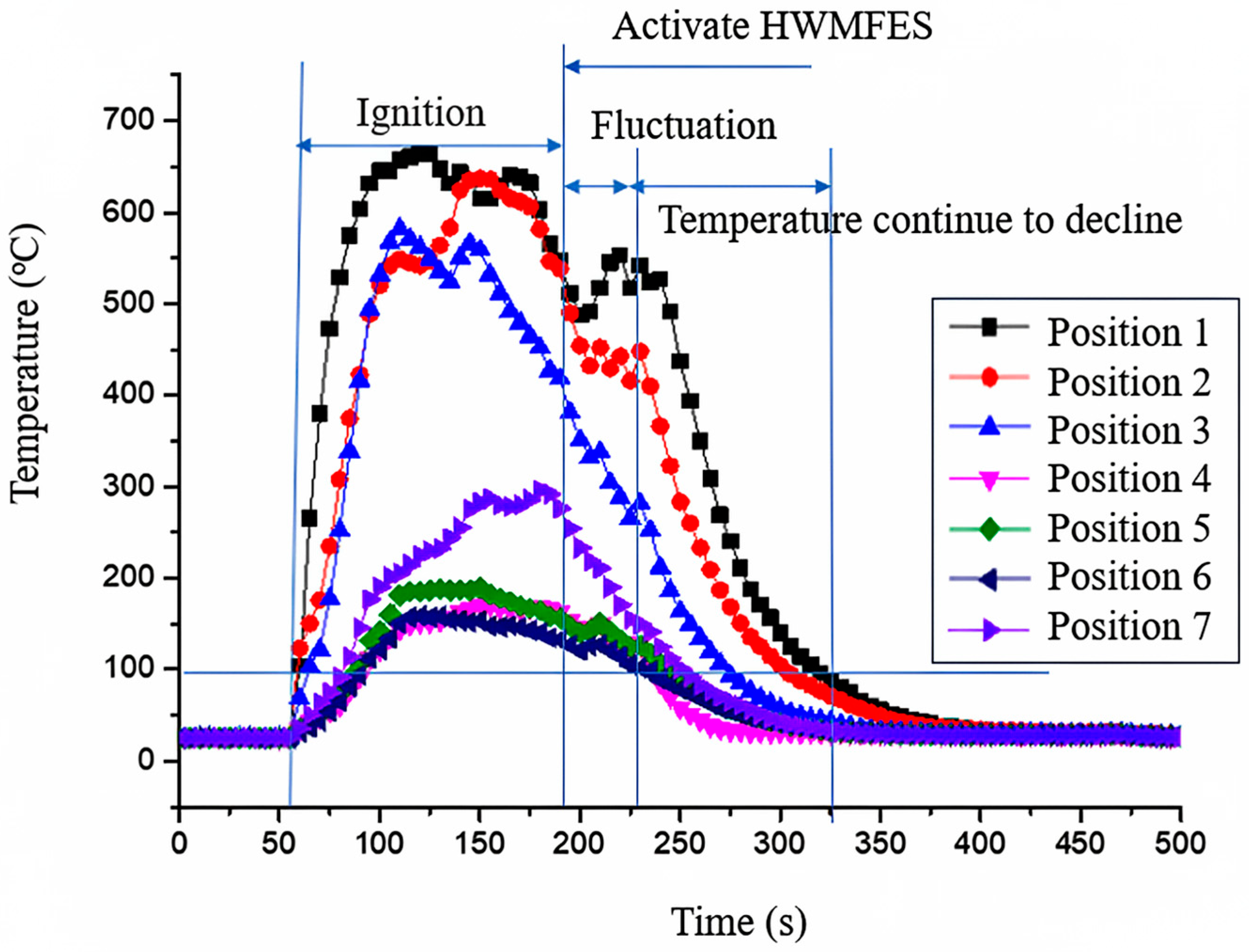
As shown in Figure 11, distinct thermal behavior emerged during the ignition phase, Position 1 (closest to the burner) exhibited the most rapid temperature increase, reaching a peak of 668 °C at 110 s after ignition. The maximum temperatures recorded at Positions 2 and 3 were 650 °C and 600 °C, respectively. Compared with the peak temperature of approximately 830 °C recorded in Test Condition 2 (with twelve cables per tray), the maximum temperatures in Test Condition 4 decreased by approximately 160 °C. This substantial reduction indicates that decreasing cable fullness effectively reduces the overall fire load and initial fire intensity.
The HWMFES was activated at 180 s after ignition. Following system activation, thermocouples at the lower positions, specifically at Position 1 and Position 2, experienced approximately 50 s of temperature fluctuation before beginning a continuous decrease. This transitional phase suggests complex interactions between the water mist application and the remaining fire plume dynamics in the lower combustion zone. In contrast, temperatures measured at higher tray layers decreased more steadily with only minor fluctuations, indicating more immediate suppression effectiveness in these regions. The time required for the HWMFES to reduce temperatures at all measured positions to 100 °C and 50 °C was 145 s and 194 s, respectively. These durations represent reductions of 14.7% and 22.5% compared to the corresponding times recorded in Test Condition 2 (170 s and 250 s with twelve cables per tray layer).
The more stable temperature decline observed at higher tray layer, with minimal fluctuations, suggests that reduced cable fullness promotes better mist penetration and distribution through the tray layers. The 50 s period of temperature fluctuation at lower positions (Position 1 and 2) after HWMFES activation can be attributed to the complex interaction between water mist application and flame stabilization mechanisms in areas with concentrated residual combustion.
The observed enhancement in HWMFES performance under reduced cable fullness can be attributed to fundamental principles of fire dynamics and suppression mechanisms. The reduction from 12 to 6 cables per tray substantially decreases the available fuel surface area, which directly affects fire development in multiple ways. According to Zhang et al. [23], the combustion characteristics and heat transfer mechanisms in cable fires are highly dependent on the available fuel surface area in ladder-type trays. With reduced cable density, the fire load decreases significantly, leading to lower heat release rates (HRR) and reduced radiative feedback to adjacent cables. This creates a less challenging environment for the HWMFES to effectively suppress the fire.
The improved suppression efficiency aligns with the findings of An et al. [24], who investigated the effects of interlayer distance and cable spacing on flame characteristics in utility tunnels. Their research demonstrated that reduced cable density results in decreased flame spread rates and lower maximum temperatures due to reduced radiative heat transfer between cables. This phenomenon explains the 160 °C reduction in peak temperature observed in our experiments when cable fullness was reduced.
Furthermore, the current results extend previous research by specifically quantifying the performance improvement of HWMFES in cable tray configurations with varying fullness levels. The 22.5% reduction in time to reach 50 °C under reduced cable fullness conditions provides valuable quantitative data for system optimization in practical applications where cable density may vary. This experimental evidence supports the implementation of cable management strategies that maintain lower cable density in critical areas of utility tunnels to enhance fire safety and suppression system effectiveness.

3.4. Impact of Longitudinal Ventilation on the Effectiveness of HWMFES

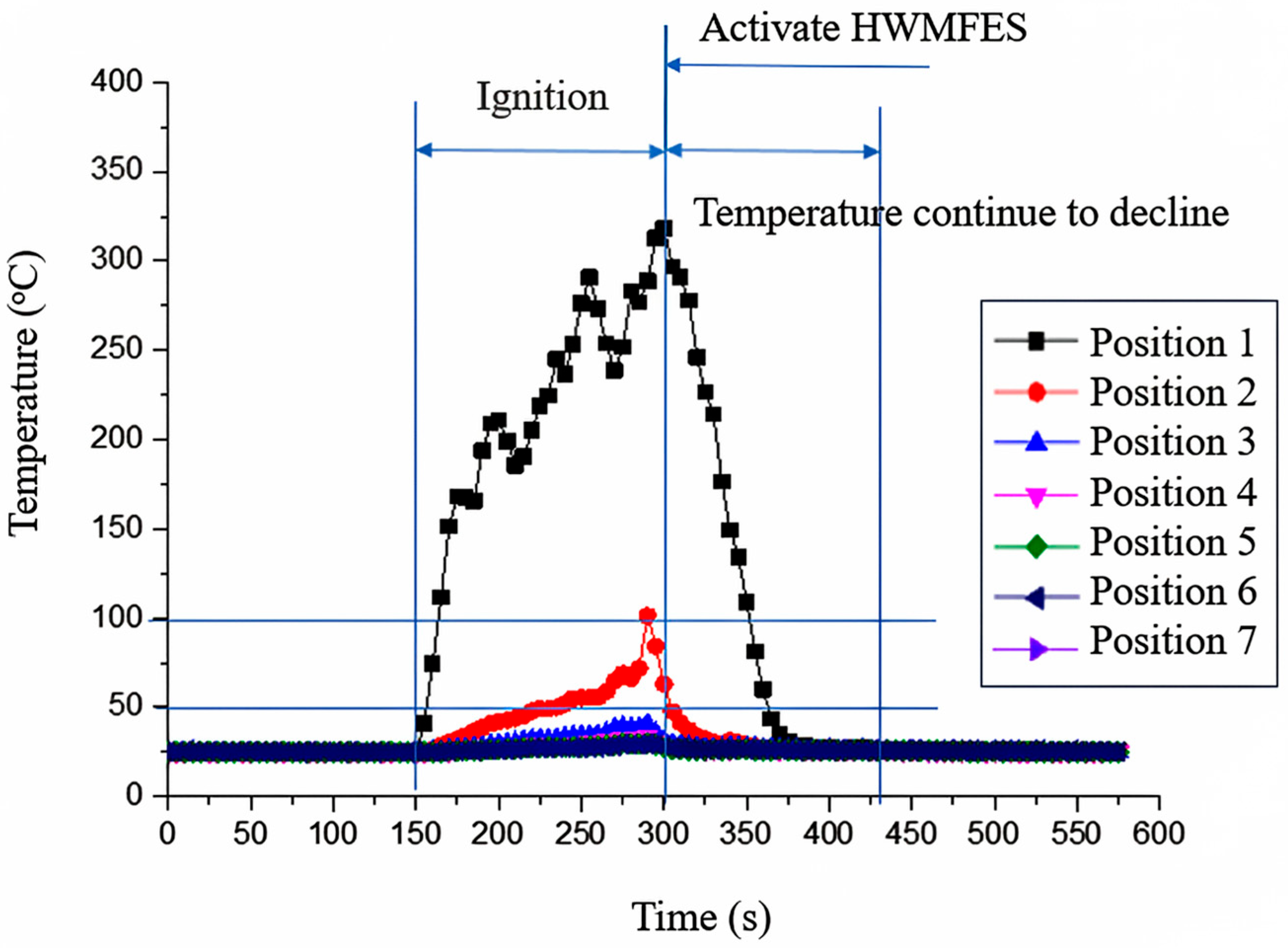
Figure 12 illustrates the temporal variation in spatial temperature distribution across vertical layers directly above the fire source under Test Condition 5, which employed a ventilation speed of 2 m/s. The experiment commenced at 0 s, with propane burner ignition occurring at 150 s. As observed in Figure 12, post-ignition temperatures exhibited distinct behavior under ventilated conditions. Position 1, closest to the fire source, showed fluctuating increases, culminating in a peak temperature of 318 °C at 150 s after ignition. In contrast, Positions 2 and 3 reached their maximum values of 102 °C and 40 °C at 137 s after ignition. Temperatures at Position 4 and above remained largely unchanged throughout the experiment. A comparative analysis with Test Condition 4 (no ventilation) revealed a significant temperature reduction across all measurement points under ventilated conditions, demonstrating that a ventilation speed of 2 m/s effectively mitigates vertical fire spread by enhancing heat dissipation and reducing thermal stratification.
This phenomenon of disrupted thermal stratification under ventilation is well-supported by previous research. Blanchard et al. [26], in their experimental and numerical study on water mist-fire interaction in an intermediate-scale tunnel, provided a detailed mechanistic explanation. They concluded that longitudinal ventilation profoundly alters the interaction dynamics, preventing the formation of stable hot gas layers and promoting a more uniform mixing of water mist with hot gases throughout the tunnel section. This prior finding offers a validated theoretical foundation for our observed “reduction in thermal stratification” and confirms that the ventilation in our test acted as a powerful mixing agent from the very beginning of the fire.
Following HWMFES activation at 302 s, temperatures at the high-temperature locations (Positions 1 and 2) decreased rapidly. The system required only 48 s and 63 s to reduce the overall spatial temperature to 100 °C and 50 °C, respectively. Compared to Test Condition 4 (no ventilation), these durations represent substantial reductions of 66.8% and 67.5%, unequivocally demonstrating that controlled longitudinal ventilation significantly enhances the fire extinguishing efficiency of HWMFES and drastically shortens extinguishing time.
The significantly improved fire extinguishing efficacy observed under longitudinal ventilation results from a synergistic combination of enhanced physical processes that collectively maximize the performance of the HWMFES. The directional airflow improves mist transport and distribution, facilitating deeper droplet penetration into the flame zone and enhancing mixing with hot gases, thereby increasing evaporation rates and cooling efficiency [20]. This critical mechanism of enhanced mist transport and gas mixing under ventilation was quantitatively analyzed by Blanchard et al. [26]. Their computational fluid dynamics (CFD) simulations demonstrated that ventilation drives the mist droplets into the core of the fire plume, significantly increasing the contact area and time between the droplets and the hot gases, which drastically improves the convective heat transfer efficiency. This finding from the literature provides a direct and robust explanation for the “enhanced mixing” and “increased evaporation rates” we hypothesize in our study, directly linking our macroscopic result (67.5%-time reduction) to a well-established micro-level physical process. Concurrently, ventilation accelerates the removal of combustion products and promotes uniform steam distribution, creating a more effective oxygen-deficient environment throughout the tunnel section [14]. Furthermore, the airflow disrupts thermal stratification, preventing the formation of stable hot gas layers that could shield the fire, while simultaneously stretching the flame structure to increase its surface area exposed to mist droplets, both mechanisms contribute to more effective cooling [21,22]. These interconnected processes explain the significantly lower peak temperatures and reduced extinguishing times observed under ventilated conditions.
Our findings align with the results of Zhu et al. [14], who reported improved cooling effectiveness of HWMFES in a tunnel model (20 m × 5 m × 5 m) under longitudinal ventilation. They attributed this improvement to enhanced mixing of water mist with hot gases and more efficient heat dissipation due to forced airflow. Moreover, the findings of Blanchard et al. [26] provide robust external corroboration for our own. Their research into water mist-fire dynamics in ventilated tunnels conclusively demonstrates that ventilation promotes mist-smoke interaction, a conclusion that aligns precisely with our experimental observations and underscores the universality of this synergistic mechanism. However, our results contrast with the conclusions of Sun et al. [19], who conducted experiments in a reduced-scale tunnel model (18 m × 1.1 m × 0.4 m) and found that a longitudinal ventilation velocity of 0.8 m/s reduced the effectiveness of their water spray system in blocking smoke diffusion. This discrepancy highlights the critical influence of scale effects on fire dynamics and suppression system performance, as emphasized by Yan et al. [27]. The larger cross-section and full-scale dimensions in our study and Zhu et al.’s work better represent real-world engineering scenarios where airflow patterns and mist-gas interactions differ significantly from those in small-scale models. The Froude modeling limitations discussed by Yan et al. become particularly relevant when considering the complex interactions between ventilation, mist transport, and fire dynamics in utility tunnel environments.
This comprehensive understanding of ventilation–suppression interaction provides crucial practical insights for designing integrated fire safety systems in utility tunnels. Our results refine the existing academic discourse on ventilation-tunnel fire interaction [25,27]. Carvel et al. [12] provided a foundational understanding of how longitudinal ventilation systems influence fires in tunnels, primarily focusing on smoke control and its effect on fire dynamics. Barbato et al. [13], in their overview, further emphasized the critical role of ventilation as a key smoke management strategy. While these studies established the importance of ventilation velocity, our findings demonstrate that in the context of an active HWMFES, a controlled longitudinal ventilation speed of 2 m/s acts synergistically with the mist, drastically enhancing its effectiveness by improving mist transport, gas mixing, and heat dissipation, rather than merely controlling the smoke flow. This highlights a sophisticated integration of active suppression and ventilation strategies, moving beyond their traditionally viewed separate functions.
Furthermore, the effectiveness of combining ventilation systems with HWMFES in a utility tunnel environment is consistent with the recommendations provided in the Technical Code for Water Mist Fire Extinguishing Systems (GB 50898-2013) [17], which acknowledges the role of controlled ventilation in certain fire scenarios while emphasizing the necessity for full-scale validation.
In summary, the integration of a moderate ventilation speed (2 m/s) with HWMFES activation creates a synergistic effect through multiple physical mechanisms—enhanced mist transport, improved oxygen displacement, thermal layer disruption, and flame stretching—that collectively optimize the fire suppression processes. This comprehensive understanding of ventilation–suppression interaction provides crucial practical insights for designing integrated fire safety systems in utility tunnels, where ventilation management during a fire incident can be strategically employed to enhance suppression system performance.

4. Conclusions

This study employed full-scale fire experiments to systematically investigate temperature distribution characteristics of cable fires in utility tunnels and quantitatively evaluate the effects of spray intensity, cable fullness, and longitudinal ventilation on the extinguishing efficiency of an HWMFES. Based on experimental results and mechanistic analysis, the following conclusions are drawn:
(1)
The maximum thermal hazard from cable fires is concentrated within the three tray layers directly above the fire source, where peak temperatures reach 825 °C, while adjacent and opposite areas experience negligible thermal impact. Fire protection design should prioritize these critical zones through a zoning approach. Thermal insulation and fire resistance requirements for structural elements should be specifically strengthened within this vertical region directly above potential ignition sources, while less stringent measures may be applied to other areas to optimize cost-effectiveness.
(2)
Increasing the spray intensity from 0.7 to 1.0 L/(min·m2) enhances cooling efficiency by 87.8%, reducing the time to achieve 100 °C by 38.2%. This finding establishes that for utility tunnel cable fire protection using HWMFES, the minimum spray intensity should be specified as 1.0 L/(min·m2).
(3)
Reducing cable fullness from 12 to 6 cables per tray decreases peak temperatures by 160 °C and reduces extinguishing time by 22.5%. These results suggest that the Standard for Urban Utility Tunnel Engineering (GB/T 50838-2015) should be revised to include maximum cable loading density provisions to ensure effective fire extinguishing system performance. This revision should be accompanied by additional design guidelines for cable arrangement and compartmentalization to maintain safe fire load levels while meeting operational requirements.
(4)
A longitudinal ventilation speed of 2 m/s increases HWMFES effectiveness by 67.5%, cutting extinguishing time from 194 s to 63 s compared to still air conditions. Consequently, relevant standards should mandate maintaining 2 m/s ventilation during fire events to optimize extinguishing performance. System designs should incorporate capabilities to sustain this optimal airflow.
(5)
The demonstrated synergistic effects between spray intensity, cable density management, and longitudinal ventilation control highlight the importance of an integrated approach to fire safety design in utility tunnels. Future design methodologies should incorporate performance-based approaches that consider these factors synergistically rather than treating individual systems in isolation.

Author Contributions

Conceptualization, K.X., P.D. and T.L.; methodology, K.X., H.L. and T.L.; investigation, T.L. and Y.F.; Data curation, K.X. and H.L.; writing—original draft preparation, K.X. and T.L.; writing—review and editing, P.D. and T.L.; supervision, K.X.; Project administration, K.X.; funding acquisition, K.X. All authors have read and agreed to the published version of the manuscript.

Funding

This research received no external funding.

Institutional Review Board Statement

Not applicable.

Informed Consent Statement

Not applicable.

Data Availability Statement

Data are contained within the article.

Conflicts of Interest

The authors declare no conflicts of interest.

References

  1. Liang, K.; Hao, X.; An, W.; Tang, Y.; Cong, Y. Study on Cable Fire Spread and Smoke Temperature Distribution in T-Shaped Utility Tunnel. Case Stud. Therm. Eng. 2019, 14, 100433. [Google Scholar] [CrossRef]
  2. Wu, J.; Bai, Y.; Fang, W.; Zhou, R.; Reniers, G.; Khakzad, N. An Integrated Quantitative Risk Assessment Method for Urban Underground Utility Tunnels. Reliab. Eng. Syst. Saf. 2021, 213, 107792. [Google Scholar] [CrossRef]
  3. Lee, B.; Lee, M.; Jung, W. Acoustic Based Fire Event Detection System in Underground Utility Tunnels. Fire 2023, 6, 211. [Google Scholar] [CrossRef]
  4. Bian, H.; Zhu, Z.; Zang, X.; Luo, X.; Jiang, M. A CNN Based Anomaly Detection Network for Utility Tunnel Fire Protection. Fire 2022, 5, 212. [Google Scholar] [CrossRef]
  5. GB/T50838-2015; Standard for Urban Utility Tunnel Engineering. Ministry of Housing and Urban-Rural Development of the People’s Republic of China: Beijing, China, 2015.
  6. Seo, H.; Chung, Y.; Song, T. An Experimental Study for Deriving Fire Risk Evaluation Factors for Cables in Utility Tunnels. Fire 2023, 6, 342. [Google Scholar] [CrossRef]
  7. Pan, R.; Zhu, G.; Liang, Z.; Zhang, G.; Liu, H.; Zhou, X. Experimental study on the fire shape and maximum temperature beneath ceiling centerline in utility tunnel under the effect of curved sidewall. Tunn. Undergr. Space Technol. 2022, 99, 103304. [Google Scholar] [CrossRef]
  8. Ye, K.; Tang, X.; Zheng, Y.; Ju, X.; Peng, Y.; Liu, H.; Wang, D.; Cao, B.; Yang, L. Estimating the two-dimensional thermal environment generated by strong fire plumes in an urban utility tunnel. Saf. Environ. Prot. 2021, 148, 737–750. [Google Scholar] [CrossRef]
  9. Jia, B.; Xia, Y.; Ning, Z.; Li, B.; Zhang, G.; Zhang, Z. Research on the Fire Extinguishing Efficiency of Low-Pressure Water Mist in Urban Underground Utility Tunnel Cable Fires. Fire 2023, 6, 433. [Google Scholar] [CrossRef]
  10. Zheng, X.; Cai, G.; Guo, J.; Gao, W.; Huang, Y.; Tong, X. Combustion characteristics and thermal decomposition mechanism of the flame-retardant cable in urban utility tunnel. Case Stud. Therm. Eng. 2023, 44, 102887. [Google Scholar] [CrossRef]
  11. Khattri, S.; Log, T.; Kraaijeveld, A. Tunnel Fire Dynamics as a Function of Longitudinal Ventilation Air Oxygen Content. Sustainability 2019, 11, 203. [Google Scholar] [CrossRef]
  12. Carvel, R.; Beard, A.; Jowitt, P. The influence of longitudinal ventilation systems on fires in tunnels. Tunn. Undergr. Space Technol. 2001, 16, 3–21. [Google Scholar] [CrossRef]
  13. Barbato, L.; Cascetta, F.; Musto, M.; Rotondo, G. Fire safety investigation for road tunnel ventilation systems—An overview. Tunn. Undergr. Space Technol. 2014, 43, 253–265. [Google Scholar] [CrossRef]
  14. Zhu, H.; Du, W.; Li, W. Experimental Study on the Influence of High-Pressure Water Mist on the Ceiling Temperature of a Longitudinally Ventilated Tunnel. Fire 2024, 7, 262. [Google Scholar] [CrossRef]
  15. Kan, D.; Feng, S.; Yan, Z.; Zhou, L.; Zhu, H. Full-scale experimental study on the smoke and thermal insulation of a water mist fire extinguishing system in a short road tunnel with natural ventilation. Tunn. Undergr. Space Technol. 2025, 158, 106414. [Google Scholar] [CrossRef]
  16. Liu, Y.; Li, Q.; Tang, Z.; Zheng, F. Effect of water mist system settings on fire and upstream smoke control in a longitudinally ventilated tunnel. Tunn. Undergr. Space Technol. 2025, 155 Pt 2, 106234. [Google Scholar] [CrossRef]
  17. GB 50898-2013; Technical Code for Water Mist Fire Extinguishing System. Ministry of Housing and Urban-Rural Development of the People’s Republic of China: Beijing, China, 2013.
  18. NFPA 750; National Fire Protection Association. Standard on Water Mist Fire Protection Systems. National Fire Protection Association: Quincy, MA, USA, 2018.
  19. Sun, J.; Zheng, F.; Tang, Z.; Tarek, B.; Bart, M. Experimental study of the effectiveness of a water system in blocking fire-induced smoke and heat in reduced-scale tunnel tests. Tunn. Undergr. Space Technol. 2016, 56, 34–44. [Google Scholar] [CrossRef]
  20. Chen, L.; Zhu, W.; Cai, X.; Pan, L.; Liao, G. Experimental study of water mist fire suppression in tunnels under longitudinal ventilation. Build. Environ. 2009, 44, 446–455. [Google Scholar] [CrossRef]
  21. Alenezi, M.; Sadek, H. Fire-suppression performance of high-pressure water mist system inside scaled-down road tunnel section. J. Eng. Res. 2023, 11, 100024. [Google Scholar] [CrossRef]
  22. Li, Q.; Tang, Z.; Fang, Z.; Yuan, J.; Wang, J. Experimental study of the effectiveness of a water mist segment system in blocking fire-induced smoke and heat in mid-scale tunnel tests. Tunn. Undergr. Space Technol. 2019, 88, 237–249. [Google Scholar] [CrossRef]
  23. Zhang, Z.; Chen, P.; Lin, Z.; Sun, S. Combustion characteristics and heat transfer mechanisms analysis of cable fire over ladder-type tray. Int. J. Therm. Sci. 2025, 215, 109935. [Google Scholar] [CrossRef]
  24. An, W.; Wang, T.; Liang, K.; Tang, Y.; Wang, Z. Effects of interlayer distance and cable spacing on flame characteristics and fire hazard of multilayer cables in utility tunnel, Case Stud. Therm. Eng. 2020, 22, 100784. [Google Scholar] [CrossRef]
  25. Song, H.; Yao, H.; Wei, X. Experimental study on fire suppression of the outdoor oil-immersed transformer by high-pressure water mist system. Fire 2023, 6, 238. [Google Scholar] [CrossRef]
  26. Blanchard, E.; Boulet, P.; Fromy, P.; Desanghere, S.; Carlotti, P.; Vantelon, J.; Garo, J. Experimental and Numerical Study of the Interaction Between Water Mist and Fire in an Intermediate Test Tunnel. Fire Technol. 2014, 50, 565–587. [Google Scholar] [CrossRef]
  27. Yan, W.; Li, C.; Zhao, P.; Gao, Z. Validation of the Froude model applicability for flame and thermal properties of tunnel fires with different cross-section scale ratios. Int. Commun. Heat Mass Transfer. 2025, 164 Pt B, 108916. [Google Scholar] [CrossRef]
Figure 1. On-site layout of the full-scale utility tunnel.
Fire 08 00404 g001
Figure 2. Utility tunnel zoning and the nozzles layout.
Fire 08 00404 g002
Figure 3. Fire source layout and propane burner. The red circle indicates the location of the fire source.
Fire 08 00404 g003
Figure 4. Layout of the ventilation fan in the utility tunnel.
Fire 08 00404 g004
Figure 5. Layout of measurement points: (a) Top view of Zone B; (b) Fire source cross-section.
Fire 08 00404 g005
Figure 6. Temporal variation in temperature directly above the fire source under Test Condition 1.
Fire 08 00404 g006
Figure 7. Temporal variation in temperature on the fire source side under Test Condition 1.
Fire 08 00404 g007
Figure 8. Temporal variation in temperature on the fire source opposite side under Test Condition 1.
Fire 08 00404 g008
Figure 9. Temporal variation in temperature directly above the fire source under Test Condition 2.
Fire 08 00404 g009
Figure 10. Temporal variation in temperature directly above the fire source under Test Condition 3.
Fire 08 00404 g010
Figure 11. Temporal variation in temperature directly above the fire source under Test Condition 4.
Fire 08 00404 g011
Figure 12. Temporal variation in temperature directly above the fire source under Test Condition 5.
Fire 08 00404 g012
Table 1. Test conditions.
Test Condition No.Number of CablesVentilation Speed (m/s)Spray Intensity (L/min·m2)
112--
212-0.7
312-1.0
46-0.7
5620.7
Disclaimer/Publisher’s Note: The statements, opinions and data contained in all publications are solely those of the individual author(s) and contributor(s) and not of MDPI and/or the editor(s). MDPI and/or the editor(s) disclaim responsibility for any injury to people or property resulting from any ideas, methods, instructions or products referred to in the content.