Article

The Application of Nitrogen Curtain Technology to Longwall Goaf to Prevent the Spontaneous Combustion of Coal: A Case Study in Shajihai Coalmine, China

1
School of Mechanics and Civil Engineering, China University of Mining and Technology (Beijing), Beijing 100083, China
2
China Coal Research Institute, Beijing 100013, China
3
State Key Laboratory of Coal Mine Safety Technology, China Coal Technology and Engineering Group Shenyang Research Institute, Fushun 113122, China
*
Author to whom correspondence should be addressed.
Fire 2023, 6(9), 363; https://doi.org/10.3390/fire6090363
Submission received: 28 August 2023 / Revised: 10 September 2023 / Accepted: 12 September 2023 / Published: 18 September 2023

Abstract

:
To enhance the inerting effect of nitrogen on large longwall goaf, a novel goaf-inerting method of using a full cross-section nitrogen curtain for a U-shaped ventilation working face is developed. The working principle of the full cross-section nitrogen curtain is elucidated. The design principle and key parameters of the nitrogen curtain needed to achieve an optimum nitrogen injection effect are established. The nitrogen curtain technology is successfully applied to the scenario of fire prevention in the underground goaf. The field study shows that the full cross-section curtain injection of nitrogen exhibits many advantages such as simple operation and homogeneous diffusion. The implementation of the nitrogen curtain reduced the maximum width of the goaf oxidation zone from 70 m to 20 m. And the CO concentration in the upper corner decreased from 21.8 ppm to 11.2 ppm after 18 h of nitrogen injection. After 48 h of injection, the CO concentration in the upper corner remained unchanged and the concentration had reduced to 0 in the lower corner. It was demonstrated that the inerting efficiency of the full cross-section nitrogen curtain reached 86% in the upper corner and 100% in the lower, which is significantly superior to the traditional buried-pipe nitrogen injection method. The effect verifies the effectiveness of the curtain injection method of nitrogen, which can ensure a safe working face production.

1. Introduction

The safety of coal production has been greatly improved with the development of longwall mining in China, while this also brings several safety problems, like the frequent occurrence of spontaneous combustion of coal in the goaf due to severe air leakage and a large amount of coal leaving [1,2,3,4,5]. To control spontaneous combustion of residual coal in longwall goaf, many techniques like grouting, inert gases injection and gel and foam injection have been developed and applied [6,7,8,9]. However, nitrogen injection has been the most widely used practice due to its easy operation and good adaptability [10,11]. When taking the technical means of nitrogen injection and fire prevention in goaf into account, the selection of a reasonable ventilation mode is one of the effective means of preventing the spontaneous combustion of the coal seam and gas overlimit, and also an important way to mitigate accidents [12]. The U-type ventilation mode is the most common application in the coal face. The characteristics of nitrogen in U-shaped ventilation are as follows: U-shaped ventilation is conducive to nitrogen moving along the potential leakage flow, and the inerting effect near the nitrogen release outlet is very obvious. The cooling range gradually decreases from near to far from the nitrogen release outlet. The time by which nitrogen injection delays the inerting of the goaf is influenced by many factors, such as the area of the goaf, the amount of air leakage, the temperature of the bedrock and the degree of spontaneous combustion of the remaining coal [13]. After the release of nitrogen, the migration trend of the nitrogen in the goaf can be divided into three categories: part of the nitrogen develops at a certain distance and forms a complex upwards vortex after kinetic energy loss or continues to flow upward slowly; the second part of nitrogen flows directly deeply into the goaf; the third part is carried by the leaked air and flows to low pressure areas such as the upper corner or drainage lane [14]. A large-flow nitrogen injection in goaf can achieve good a inerting effect, which decreases gradually with the advance of the working face position. While the low-flow nitrogen injection moves forward with the position of the working face, the position of the fireproof line retracts to the working face, and then expands to the depth of the goaf, that is, the fire prevention effect has an inflection point at the position of nitrogen injection. With U-shaped ventilation, the oxidation zone of goaf presents an asymmetric distribution on the inlet and return air sides, and the spontaneous combustion zone has the widest range on the inlet air side. The closer it is to the return air side, the smaller the range of the spontaneous combustion zone is and the more forward the location is. The influence of nitrogen injection on oxygen distribution can be summarized by two points: the local influence is that the oxygen concentration near the nitrogen injection port changes obviously, while the macro influence is that the oxidation zone retracts and moves forward, and the influence degree decreases from the inlet side to the return side.
Currently, nitrogen injection is mainly accomplished through pre-buried pipe, drag pipe, borehole and intubation pipe [15,16,17,18,19,20,21]. For the pre-buried pipe method, seamless steel pipe is placed along the main gate of the working face first. And then, when the working face advances to a certain position, the pipeline valve is opened, and nitrogen is released at the end of the pipe. Additionally, for the drag pipe nitrogen injection method, the injection pipe is placed in the intake roadway along the goaf, and the pipe moves forward under the screw motor traction in the transportation traction head or mechanical winch in the roadway. For this method, the stepping distance for the drag pipe is definite, which ensures the exit position is always in the oxidation zone. The borehole nitrogen injection method has a significant advantage compared with other methods, which is directionality, which can infuse the large-flow nitrogen into the spontaneous combustion area. The intubation pipe nitrogen injection method is appropriate to use when the mine fire originates in the open-off cut or stopping line of the working face.
The air leakage greatly impacts the inerting effect of nitrogen injection. The air leakage in the goaf is mainly distributed in three characteristic areas, namely, the upper corner air leakage area, the rear frame air leakage area and the lower corner air leakage area. There is a nonlinear relationship between the air leakage intensity and the distance from a certain point in the goaf to the working face. The air leakage rate in the goaf gradually decreases along the working face tendency and flows out of the goaf in the reverse direction, to a position in the middle. U-shaped ventilation is conducive to nitrogen moving along the potential leakage flow, and the cooling range decreases from points near to the nitrogen injection outlet to points far from it. There are three main migration laws of nitrogen in the goaf after release.
In addition, the nitrogen injection methods mentioned above also have three shortcomings. First, the nitrogen diffusion radius is small and the effective scope is limited. Second, the nitrogen diffusion is very likely to be affected by air leakage which results in an inhomogeneous distribution in the goaf. Third, the nitrogen injection quantity is small, which restricts the nitrogen diffusion in the goaf. However, the more serious challenge for nitrogen injection is the successive emergence of large longwall panels, where the mining height of the top-coal caving face can reach up to 20 m and the working face is generally longer than 200 m. In addition, a weakened air leakage and a poor nitrogen diffusion in the goaf, because of working face enlarges the distance between the return and intake roadway, is a challenge [22,23,24,25]. The inferior applicability of traditional nitrogen injection techniques greatly restricts their inert effectiveness in a huge goaf. In this paper, a new full cross-section curtain method of injecting nitrogen is developed to improve the nitrogen inerting effect, by creating multi-row nitrogen injection ports to replace the single horizontal nitrogen injection ports. The issues around conventional nitrogen injection are solved through forming a universal coverage in the goaf. Moreover, it exhibits a more obvious superiority in the tailgate and middle goaf due to its special design in the three-dimensional space. To investigate the performance of the curtain nitrogen injection method, the basic principles and the key design concepts are introduced in this paper. Additionally, in accordance with the above results, the industrial practice is carried out to evaluate the inert effect of full cross-section nitrogen injection.

2. Principle and Methods

2.1. The Principle of Full Cross-Section Curtain Injection of Nitrogen

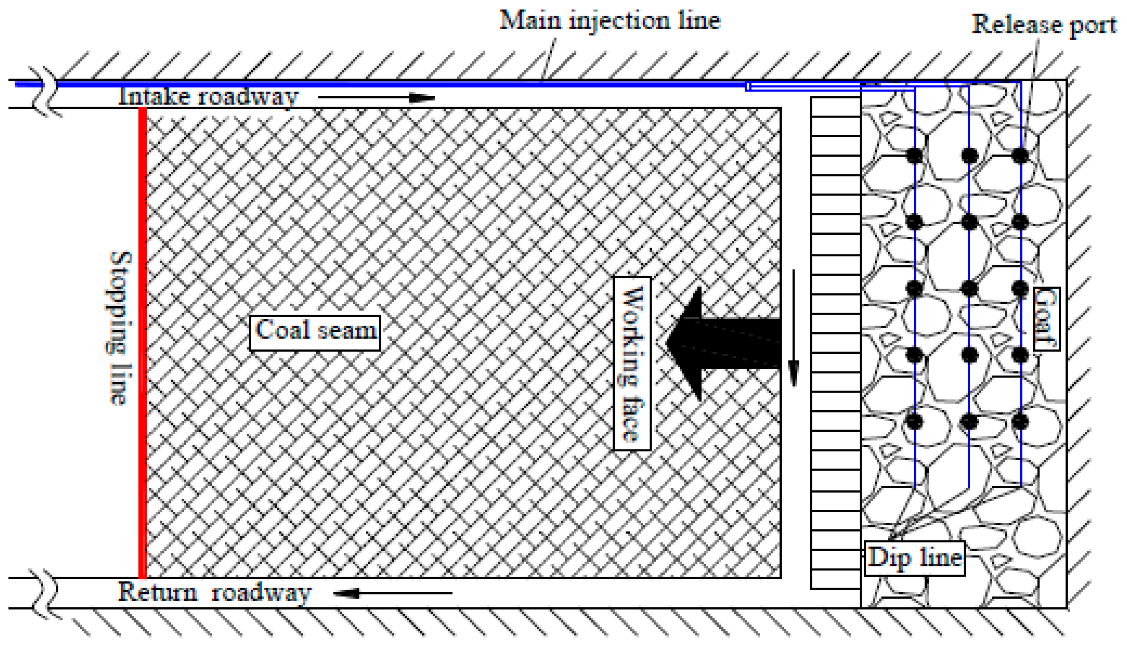
The conventional nitrogen injection layout of pre-buried pipe is shown in Figure 1. As can be seen from Figure 1, the pre-buried pipe is placed at the bottom of the main gate and the pipe port is positioned in the goaf with a distance of 20–40 m to the working face. And the nitrogen discharge valve is open when the working face advances to an appropriate position. Under the driving effects of air leakage along the working face, the nitrogen is introduced to the entire goaf, diluting the oxygen concentration and restraining the gas explosion in the spontaneous combustion zone [26].
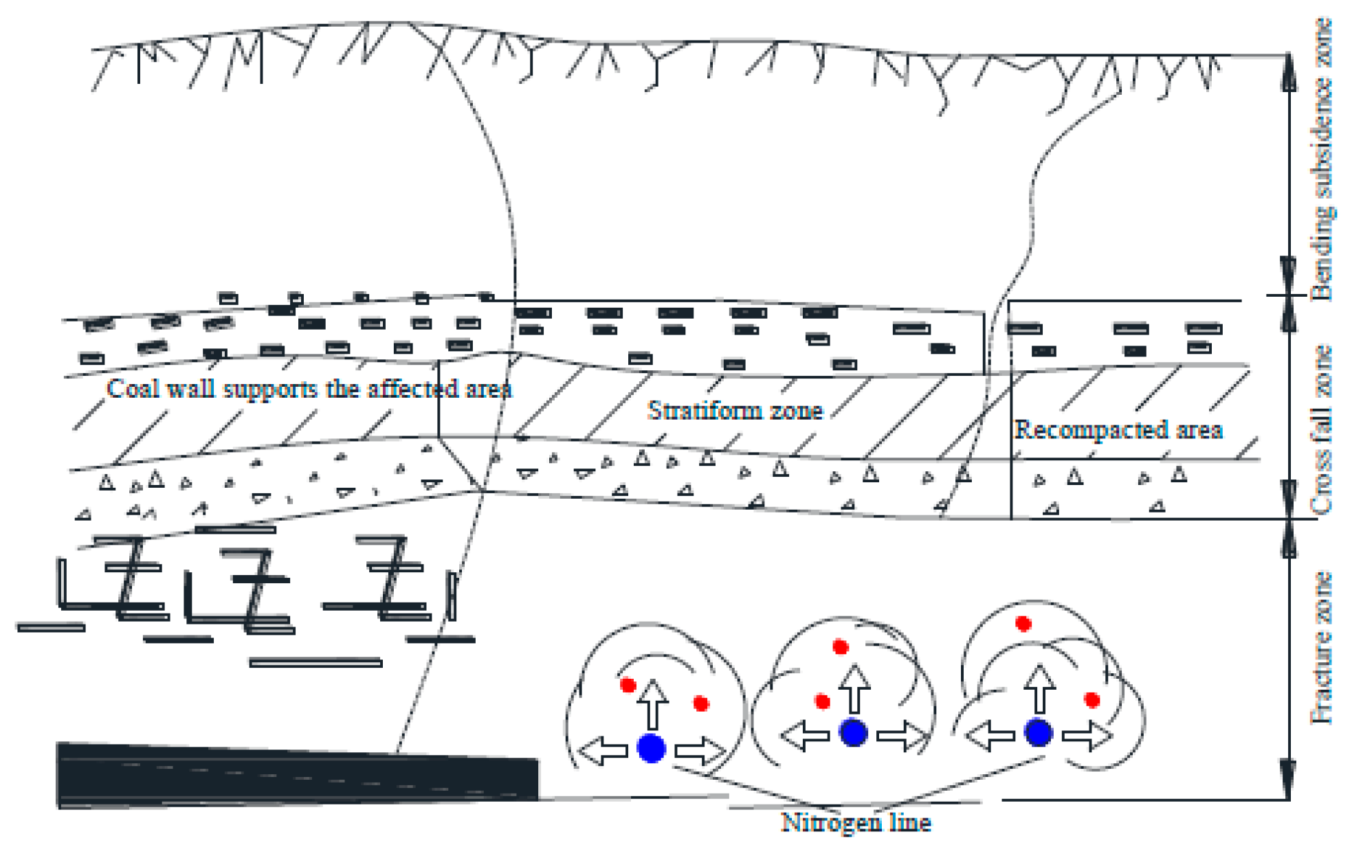
The full cross-section curtain injection of nitrogen is established based on the existing pre-buried pipe, as shown in Figure 2. And the key technical innovation is the nitrogen injection port layout which is a circumferential collocation around the nitrogen pipe. The nitrogen pipes are arranged along the working face, and are uniformly spaced and parallel mounted in the goaf. To achieve a uniform inerting effect and reduce the nitrogen injection amount, the cell hole sizes are specially set in the nitrogen pipe. With the nitrogen pipe laid successively in the scraper-trough conveyer, the nitrogen is continuously released, and a nitrogen curtain is formed in the goaf. The three-dimensional nitrogen diffusion created by the curtain is preferable for dealing with the large-scale hidden fire zone. And the diffusion effect of the full cross-section curtain injection of nitrogen is shown in Figure 3.

2.2. The Design of Full Cross-Section Curtain Injection of Nitrogen

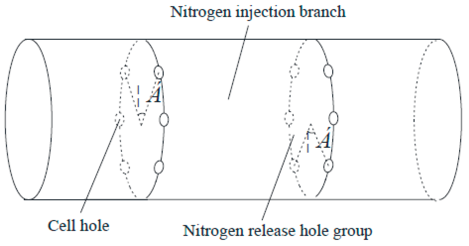
The basic design principle for full cross-section curtain injection of nitrogen is to obtain a rapid efficient inerting in the goaf with a low cost. The oxidation zone advances in the goaf as the working face moves forward. Thus, it is a challenge to realize a homogeneous nitrogen diffusion in the goaf, especially in the oxidation zone. The key technique is to design the hole group and cell hole of the nitrogen curtain pipe, as shown in Figure 4. To obtain a better diffusion effect, one hole group is designed for six cell holes, which are evenly distributed around the pipe with an angle of 60° and a radius of 1 cm. The nitrogen pipe array pitch is two times the nitrogen diffusion radius to avoid the overlap of the coverage of two groups of nitrogen release ports.
Since nitrogen release is a coupling process of gas injection and expansion, related to the exchange of momentum, mass and heat between nitrogen and the gas mixture in the goaf, a turbulent free jet is always produced at the nitrogen outlet and the momentum remains constant along the jet axis. The expansion process originates from the hole port and throughout the whole goaf. The nitrogen generates a sudden expansion with a pressure decline, forming a semicircular ball around the hole port [27,28,29,30]. The movement of nitrogen after its release from the pipeline can be divided into two stages, both of which are closely related to time. At the initial stage, nitrogen migration is mainly affected by jet flow and expansion, and the effects of gravity and drag can be ignored. As gas diffuses between coal voids in the goaf, resistance, gravity and buoyancy gradually become the main influencing factors, and the migration velocity decreases gradually. When the velocity attenuates to a certain extent, the resultant force of nitrogen reaches an equilibrium state. Accordingly, there are three migration paths for nitrogen in the goaf: first, it diffuses directly to the deep part of the goaf under the influence of the jet flow; second, it slowly flows upward after reaching the equilibrium state; and third, it flows downward to the corner and other areas under the influence of negative pressure.
The nitrogen injection number n0 and hole group number n1 are calculated according to Equations (1) and (2).
n 0 = L y L b
n 1 = L z L b + 1
where Ly is the maximum width of the goaf oxidation zone, m; Lz is the length of the working face, m; Lb is the nitrogen injection pipe array pitch, m; and Lb is calculated using Equation (3).
L b = 2 ( S c + L c )
where Sc is the displacement caused by jet action when nitrogen in the goaf reaches critical state, m; Lc is displacement caused by expansion action when nitrogen in the goaf reaches a critical state, m; Sc is calculated [31] using Equation (4); and Lc is calculated using Equation (5).
S c = 24.8 V 0 r t c
L c = 3 V 0 r 2 ρ 1 ρ 0 t c 3
where V0 is jet velocity when nitrogen is released from the hole, m/s; r is nitrogen release hole radius, m; ρ1 is nitrogen density in nitrogen injection tube, kg/m3; ρ0 is nitrogen density under ambient conditions, kg/m3; and tc is time for nitrogen in goaf to reach critical state, s. V0 is calculated using Equation (6) and tc is calculated using Equation (7).
V 0 = k λ 2 k j k j 1 R T 1 [ 1 ( p 0 p 1 ) k j 1 k j ]
where λ is the orifice velocity coefficient, generally considered 0.98; kj is the nitrogen adiabatic coefficient, taken to be 1.4; k is goaf porosity; R is molar gas constant, J/(mol·K); T1 is the temperature prior to nitrogen release, K; p1 is the pressure prior to nitrogen release, Pa; and p1 is standard atmospheric pressure, Pa.
t c = 6.2 r V 0 V C 2
where Vc is the velocity when the nitrogen in the goaf reaches a critical state, m/s, and Vc is calculated by Equation (8).
V C = 8 3 C D ( ρ 2 ρ 0 ρ 2 ) g r
where ρ2 is gas density in goaf, kg/m3; CD is the gas release coefficient; and g is acceleration of gravity, m/s2.

3. Field Application

To study the effect of the process of full cross-section curtain injection of nitrogen, the field demonstration is carried out in the B1003W01 working face of the Shajihai coalmine of Shenhua Guoneng Group.
The discharge pressure of nitrogen injection in the B1003W01 working face was 250,000 Pa, the temperature was 293.15 K, the porosity of the goaf was 0.2 and the radius of the single hole of nitrogen injection was 1 cm. The nitrogen density in the nitrogen injection pipeline was 2.30 kg/m3, the nitrogen density in the ambient state was 1.16 kg/m3, the gas density in the goaf was assumed to be 1.19 kg/m3 and the gas release coefficient was 1.00. The length of the working face is 219.4 m, and the maximum width of the oxidation zone in the goaf is 70 m. By adopting the relevant formulae from Section 3, the spacing of the full cross-section nitrogen injection curtain pipelines in the goaf is 39 m, the number of nitrogen injection pipelines in the goaf is three and the groups of nitrogen release ports is 22.

3.1. Layout and Operation

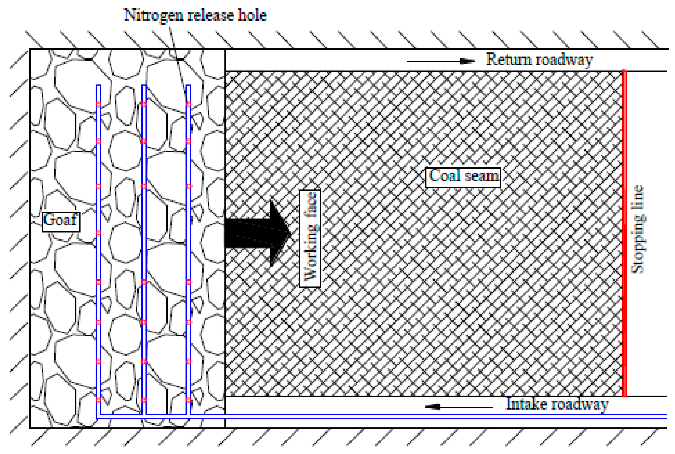
Figure 5 illustrates the field layout of the full cross-section curtain injection of nitrogen in the goaf. In the field application, the first nitrogen injection pipe is laid along the direction of the cut-off line in the working face. The nitrogen discharges from the pipe port after flowing through the nitrogen generator, main nitrogen pipe, bypass valve and pressure hose. The second nitrogen injection pipe is immediately established when the working face advances at the distance of the array pitch. According to this operation, the goaf will always be effectively covered by nitrogen.
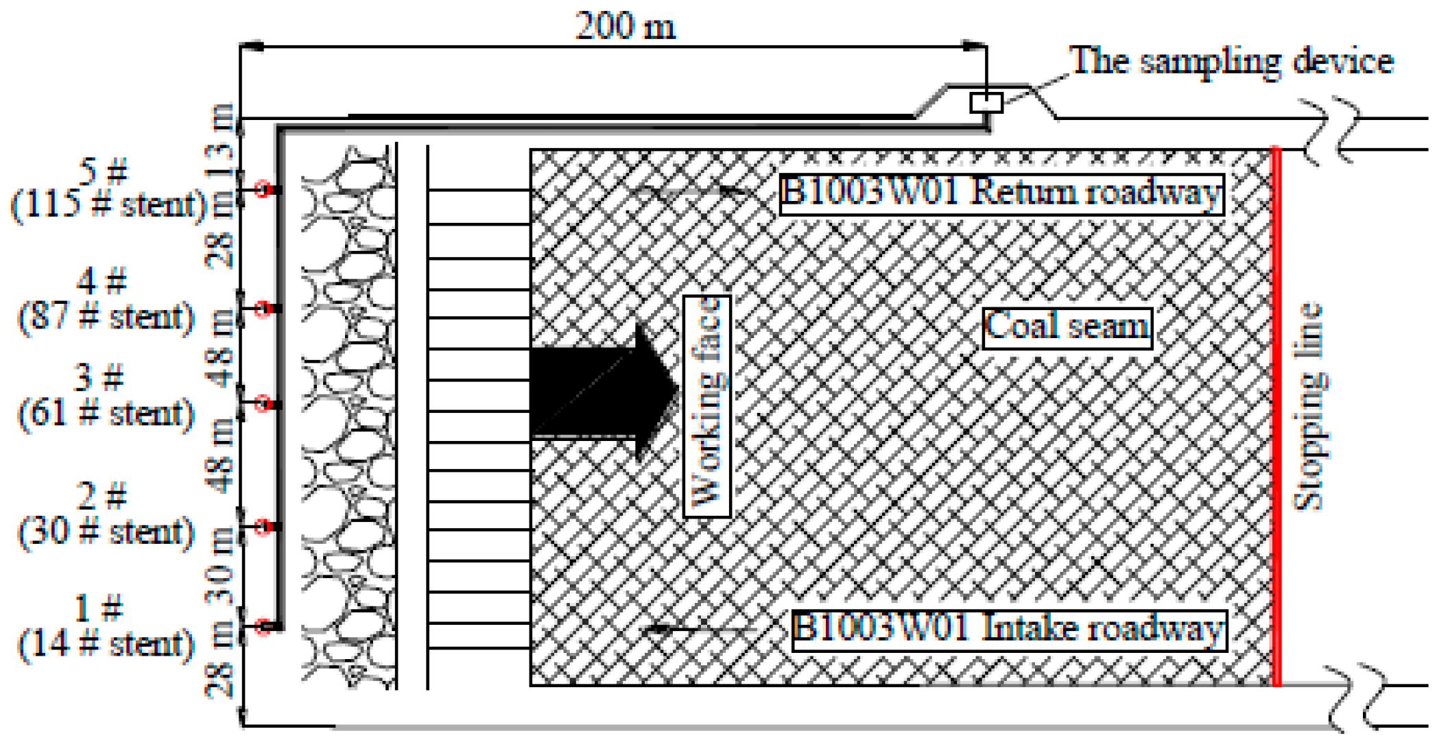
Five monitors are placed behind the longwall support of the working face to investigate the inerting effect of curtain injection of nitrogen. The monitors are marked as 1#, 2#, 3#, 4#, and 5# from the longwall tailgate, respectively. The 1# monitoring point is set 28 m from the intake roadway and the 5# monitoring point is set 13 m from the return roadway. The distance between the 1# monitoring point and the 2# monitoring point is 30 m. The other monitoring point distances are all 48 m, as shown in Figure 6.

3.2. Effect Investigation

3.2.1. Change in Oxidation Zone Width

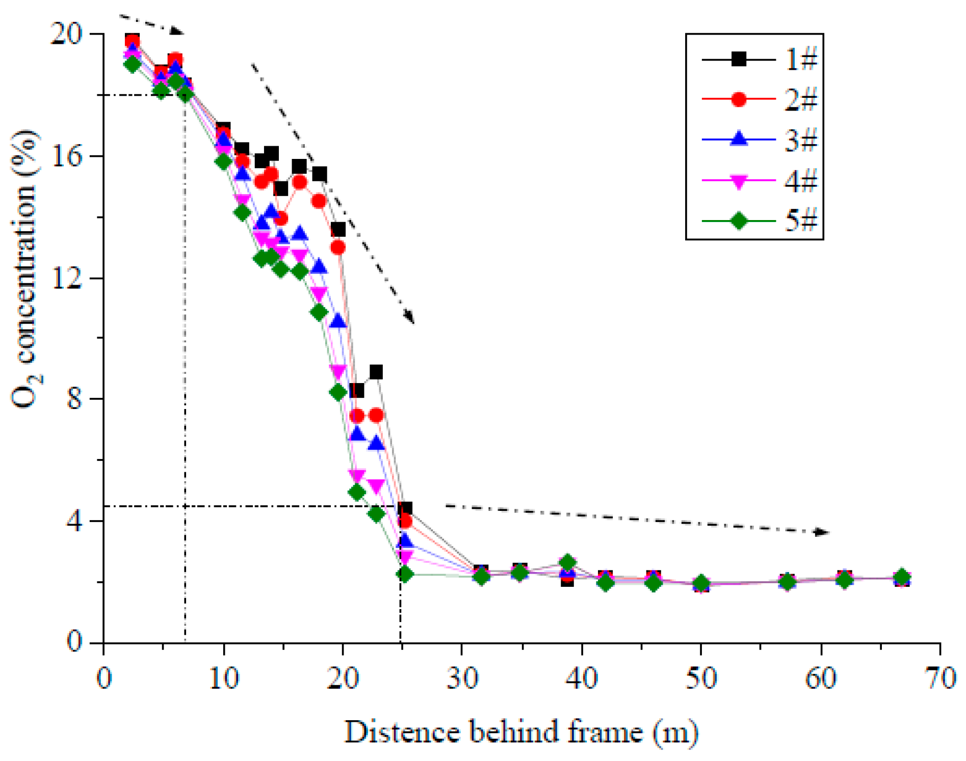
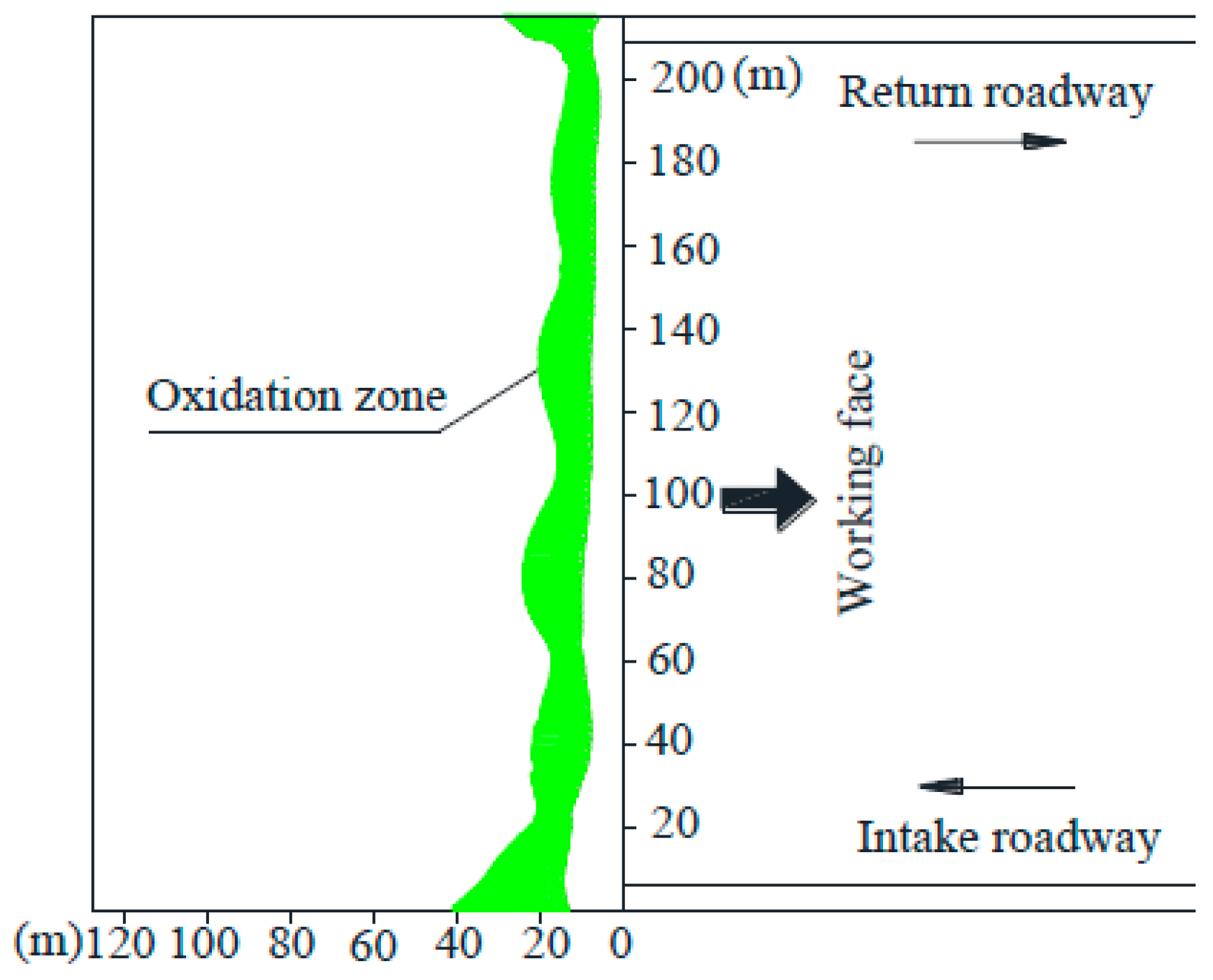
Figure 7 presents the evolution of oxygen concentration in the goaf after being affected by the full cross-section curtain method of injecting nitrogen. It can be seen that the variation trend for all monitoring points is consistent, indicating that the inerting effect of curtain injection of nitrogen is uniform. The oxygen concentration reduces with the increase in buried distance, to about 18% when the monitoring point is placed about 7 m in to the goaf. And when the oxygen concentration presents a sharp reduction at the buried distance of 7–25 m, the oxygen concentration of the 5# monitoring point is the minimum while at the 1# monitoring point, it is the maximum. Additionally, since the oxygen concentration remains lower than 7% when the buried distance is larger than 25 m, this remarkable oxygen concentration reduction indicates that the nitrogen curtain exhibits a superior inerting performance in the goaf. The oxygen distribution is measured all across the goaf based on the monitoring point date, as shown in Figure 8.
The oxygen concentration range in which coal may spontaneously combust is 7–18% in the goaf [32]. Thus, the width of the oxidation zone is compared between the conventional pre-buried pipe and the full cross-section curtain injection of nitrogen. The oxidation region width for the conventional pre-buried pipe is 27–100 m on the intake side, 20–90 m in the middle and 18–80 m on the return side. The oxidation region width has been significantly reduced with curtain injection of nitrogen, to 10–40 m on the intake side, 10–30 m in the middle and 7–30 m on the return side. Meanwhile, the oxidation zone’s position clearly advances, which also verifies the excellent inerting effect of the full cross-section curtain injection of nitrogen. The inerting effect is significantly better than the existing nitrogen injection tested [33], where eight nitrogen injection trials were conducted and the inerting effect was confirmed to be limited for the working face at a flow ratio of 900 m3/h. In addition, Zhu et al. 2013 also carried out research and discovered that the conventional pre-buried pipe may adversely enlarge the oxidation zone as the injection port position embeds in the goaf.

3.2.2. CO Concentration in the Working Face Corner

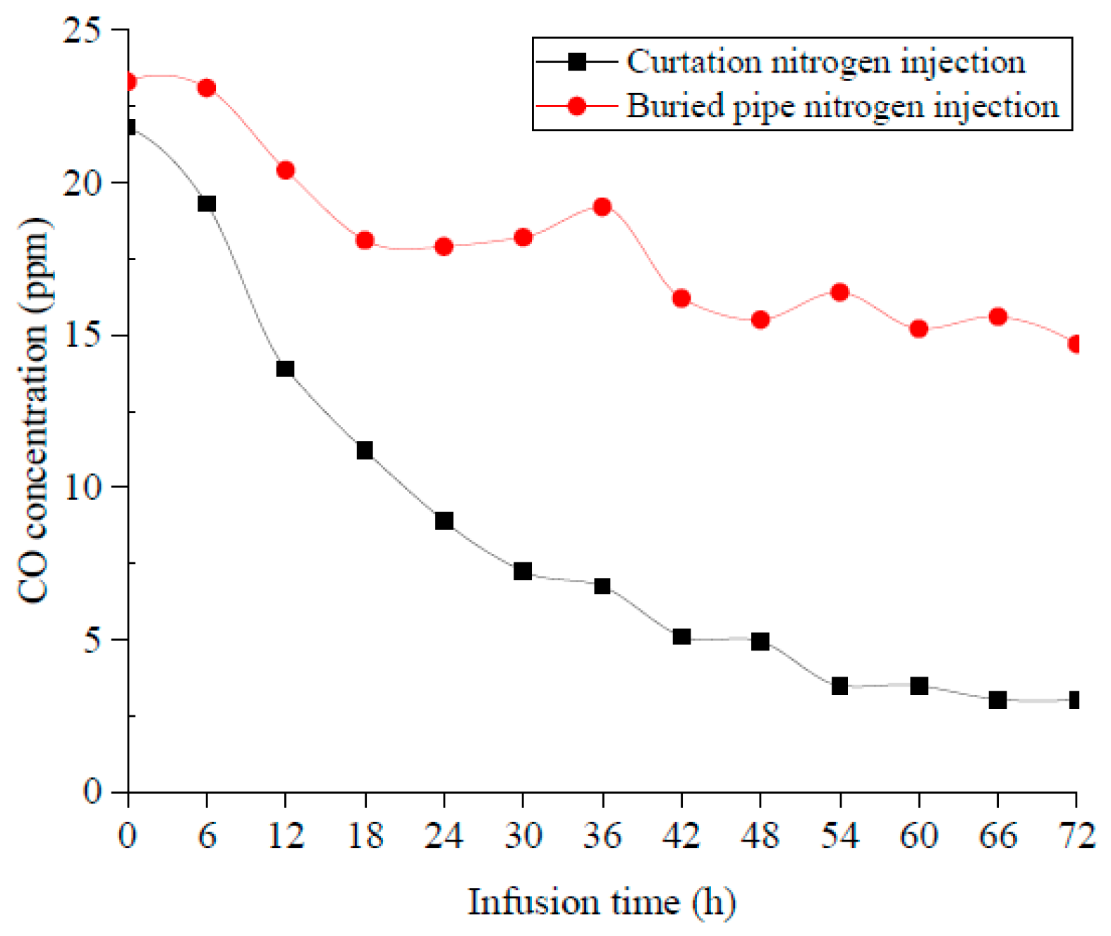
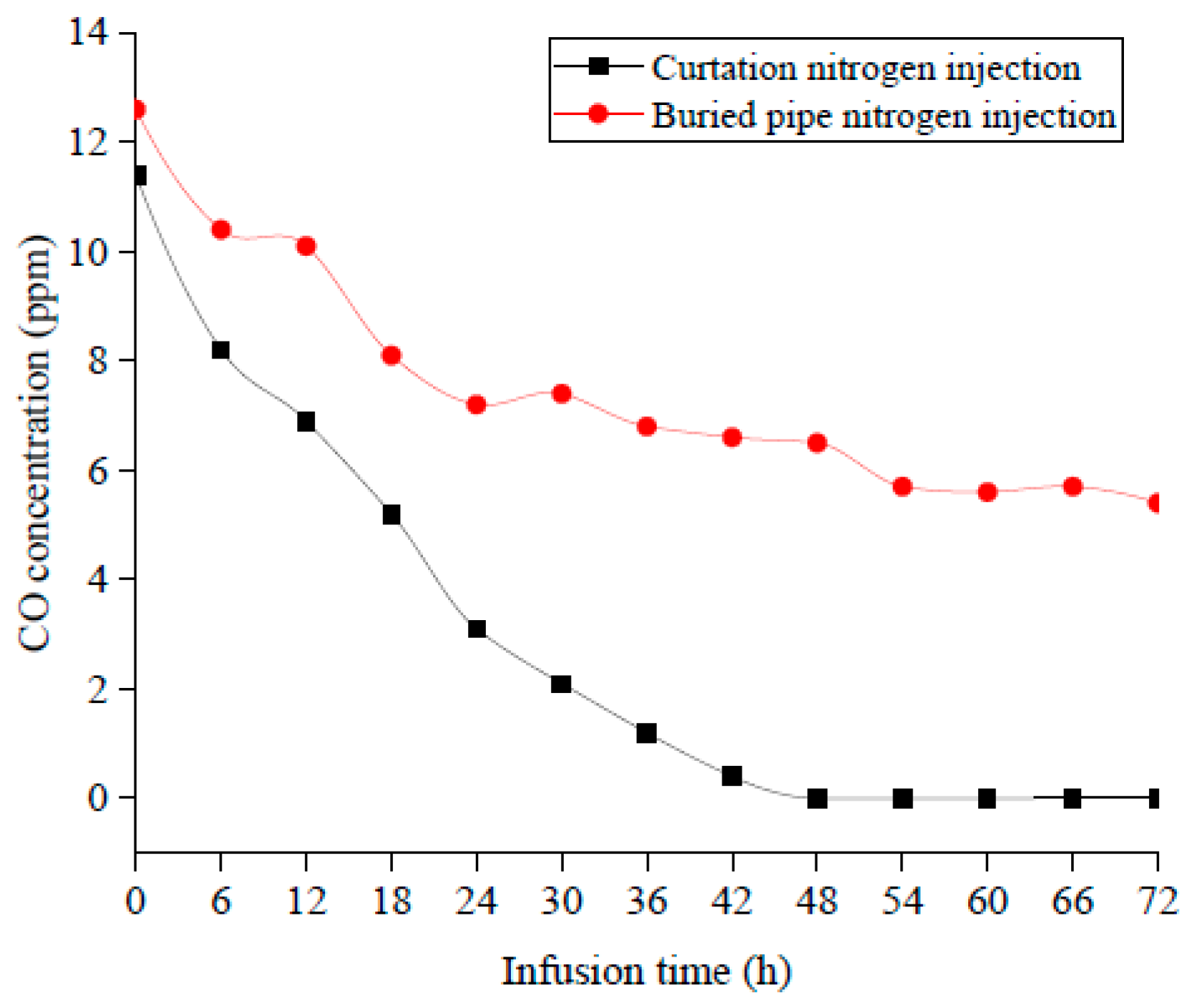
The CO concentration change is a key indicator of gas produced by coal oxidation, which can be used to evaluate the inerting effect of the full cross-section curtain injection of nitrogen and the buried pipe injection of nitrogen. The evolution of CO concentration with injection time in the upper corner is plotted in Figure 9. The nitrogen injection amounts are both 900 m3/h, and the CO concentrations in the upper and lower corner were measured every 6 h for a total of 72 h.
It is found that the CO concentration reduces in both scenarios after nitrogen injection. The upper corner CO concentration decreases from 21.8 ppm to 11.2 ppm after curtain injection of nitrogen for 18 h and the CO concentration tends to stabilize at 3 ppm after 48 h. However, the CO concentration is still as high as 18.1 ppm after 18 h for buried pipe injection of nitrogen. Figure 10 displays the CO concentration change in the lower corner, which decreases from 11.4 ppm to 0 ppm after 48 h for the curtain injection of nitrogen, while the CO concentration is still 6.5 ppm for the buried pipe injection of nitrogen.
It is a significant result that the effect of buried pipe nitrogen injection is only obvious in the early stage, while it is difficult to maintain its effectiveness over most of the relevant time period and the region of the spontaneous combustion zone due to its limited inerting ability. Therefore, the CO concentration remains at a high level and even rebounded because of the coal re-oxidation. In comparison, the inerting effect of curtain injection of nitrogen is distinctly superior to the conventional buried pipe method because the new nitrogen injection method results in a lower CO concentration.

3.2.3. The Nitrogen Inerting Efficiency

The nitrogen release process in the goaf is the coupling of a jet process and an expansion process. In essence, the jet process during nitrogen release is the exchange of momentum, mass and heat between nitrogen emitted from the orifice and the mixed gas in the goaf. A turbulent free jet is usually formed at the nitrogen release orifice, and the momentum remains unchanged along the jet axis. The expansion process of nitrogen release is carried out on the circular orifice, and nitrogen is rapidly expanded and depressurized after being released from the orifice. Its expansion shape is assumed to be semicircular.
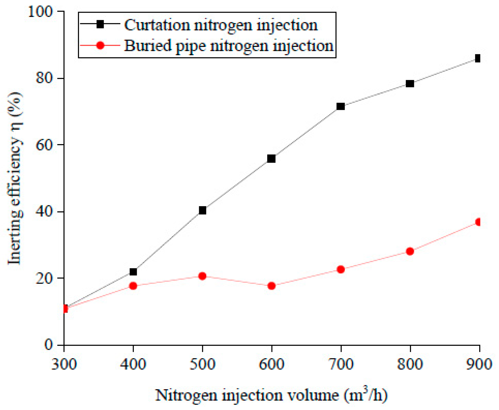
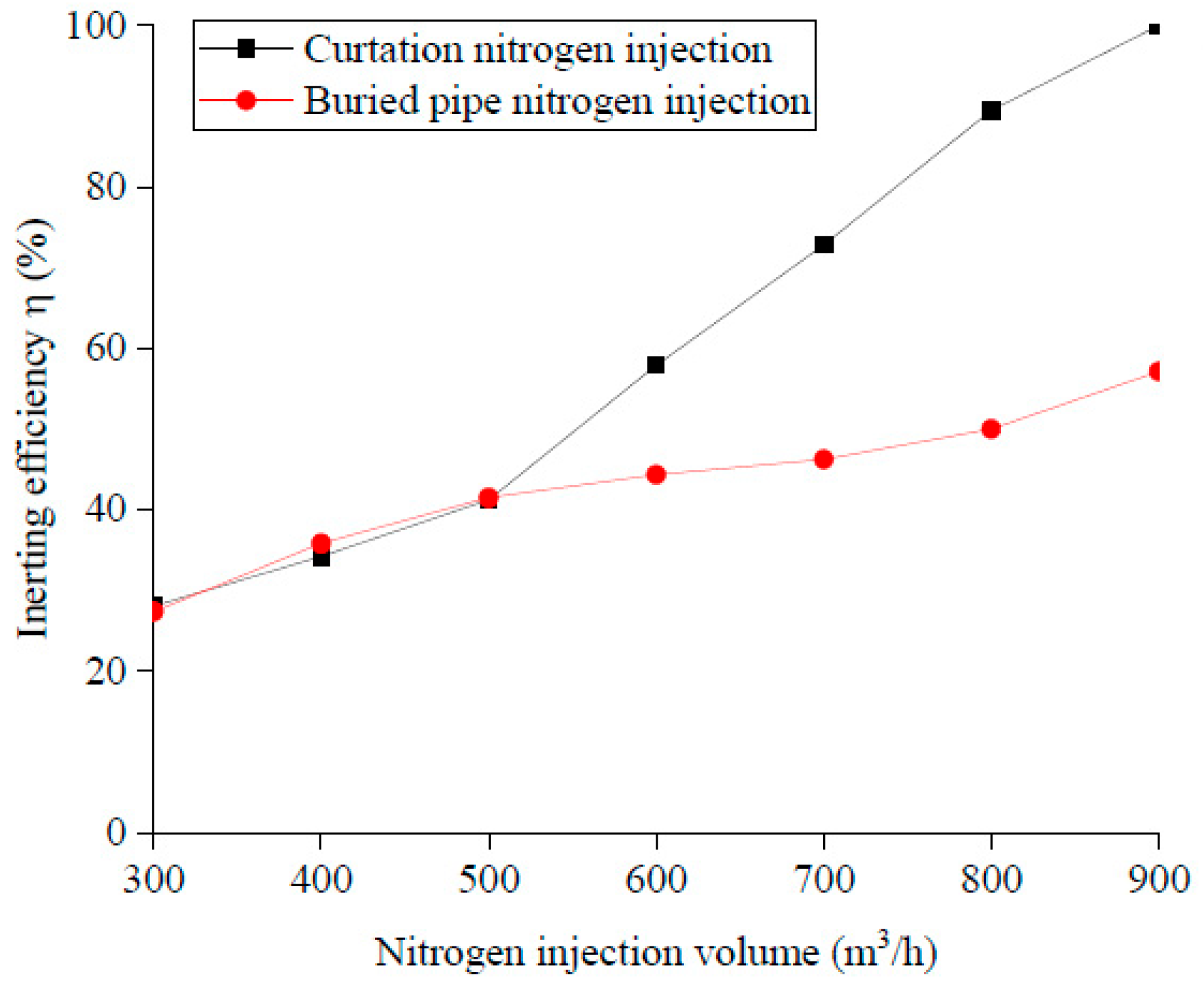
The nitrogen inerting efficiency refers to the reduction amplitude of the upper (lower) corner CO concentration under different nitrogen injection conditions, which is expressed by Equation (9).
η = C co C initialco = C initialco C terminalco C initialco
where Cinitialco is the original CO concentration without nitrogen injection, ppm, and Cterminalco is the CO concentration after nitrogen injection, ppm.
A total of seven experiment groups are conducted in an underground field with nitrogen injection amounts of 300 m3/h, 400 m3/h, 500 m3/h, 600 m3/h, 700 m3/h, 800 m3/h and 900 m3/h. The reductions in the upper and lower corner CO concentration are tested successively. Figure 11 and Figure 12 present the nitrogen inerting efficiency at the upper and lower corner under different nitrogen injection amounts, respectively. It is found that the nitrogen inerting efficiency is improved significantly with the application of a curtain injection of nitrogen. As the nitrogen injection amount rises from 300 m3/h to 900 m3/h, the upper corner inerting efficiency increases from 11% to 86% and the lower corner inerting efficiency grows from 28% to 100%. Nevertheless, the upper corner inerting efficiency only remains at 10–37% and the lower corner at 27–57% when the traditional buried pipe nitrogen injection is used, which also reflects that the curtain injection of nitrogen works in terms of reducing the nitrogen injection amount and enhancing the inerting efficiency.

4. Conclusions

In this paper, the nitrogen curtain technology applied on longwall goaf to prevent the spontaneous combustion of coal was studied in Shajihai Mine, Ta Cheng China. The conclusions can be summarized as follows:
(1)
The working principle of full cross-section curtain injection of nitrogen is elucidated and the design principles and key parameters of the nitrogen curtain are established, such as the nitrogen injection port layout, the nitrogen injection pipe array pitch, the number of hole groups and the cell hole radius. And from the above results, we know that the nitrogen injection hole groups should be evenly spaced, and that the closer the cell hole is to the inlet side, the smaller the radius is, which ensures the consistency of the amount of nitrogen released.
(2)
The field application was carried out in the B1003W01 working face to investigate the inerting effect of the nitrogen curtain technology. It is proved that the full cross-section curtain injection of nitrogen exhibits a superior extinguishment performance of goaf fires compared with the conventional buried pipe nitrogen injection method. After implementing curtain injection of nitrogen, the maximum width of the goaf oxidation zone is reduced from 70 m to 20 m and the upper corner CO concentration decreases from 21.8 ppm to 11.2 ppm after 18 h of nitrogen injection. Additionally, the upper corner CO concentration tends to stabilize at 3 ppm and the lower corner CO concentration drops to 0 ppm after 48 h.

Author Contributions

Conceptualization, H.-J.G.; methodology, H.-J.G., X.-L.L. and F.-C.T.; formal analysis, H.-J.G. and Y.-M.Z.; investigation, H.-J.G. and F.-C.T.; resources, Y.-M.Z.; data curation, H.-J.G. and X.-L.L.; writing—original draft preparation, H.-J.G.; writing—review and editing, Y.-M.Z., X.-L.L. and F.-C.T.; project administration, F.-C.T.; funding acquisition, Y.-M.Z. and F.-C.T. All authors have read and agreed to the published version of the manuscript.

Funding

This research was funded by National Natural Science Foundation of China (Grant No. 52174230, 52174229), the Natural Science Foundation of Liaoning Province (2023-MS-355).

Data Availability Statement

Not applicable.

Conflicts of Interest

The authors declare no conflict of interest.

References

  1. Wang, D.M. Mine Fire Science; China University of Mining and Technology Press: Xuzhou, China, 2008. [Google Scholar]
  2. Wang, L.K.; Ren, T.X.; Nie, B.S.; Chen, Y.; Lv, C.Q.; Tang, H.Y.; Zhang, J.F. Development of a spontaneous combustion TARPs system based on BP neural network. Int. J. Min. Sci. Technol. 2015, 25, 803–810. [Google Scholar] [CrossRef]
  3. Liang, Y.T.; Hou, X.J.; Luo, H.Z. The current situation and countermeasures of coal mine fire control in China. Coal Sci. Technol. 2016, 44, 1–6. [Google Scholar] [CrossRef]
  4. Mohalik, K.; Ray, M.; Varma, S. Application of CFD techniques to assess spontaneous heating/fire during extraction of thick coal seam using blasting gallery (BG) method. Combust. Sci. Technol. 2020, 192, 1772–1784. [Google Scholar] [CrossRef]
  5. Tian, L.; Liu, S.; Li, Y. Application of inorganic solidified foam to control the coexistence of unusual methane emission and spontaneous combustion of coal in the Luwa coal mine, China. Combust. Sci. Technol. 2020, 192, 638–656. [Google Scholar] [CrossRef]
  6. Zhou, F.B.; Ren, W.X.; Wang, D.M. Application of the three-phase foam to fight an extraordinarily serious coal mine fire. Int. J. Coal Geol. 2006, 67, 95–100. [Google Scholar] [CrossRef]
  7. Ray, S.K.; Singh, R.P. Recent developments and practices to control fire in underground coal mines. Fire Technol. 2007, 43, 285–300. [Google Scholar] [CrossRef]
  8. Lu, X.X.; Wang, D.M.; Qin, B.T.; Tian, F.C.; Shi, G.Y.; Dong, S.J. Novel approach for extinguishing large-scale coal fires using gas-liquid foams in open pit mines. Environ. Sci. Pollut. Res. 2015, 22, 18363–18371. [Google Scholar] [CrossRef]
  9. Guo, Q.; Ren, W.X.; Shi, J.T. Experimental investigations on foaming device used for coal spontaneous combustion prevention. Combust. Sci. Technol. 2020, 192, 1850–1862. [Google Scholar] [CrossRef]
  10. Adamus, A. Technical note: Review of nitrogen as an inert gas in underground mines. J. Mine Vent. Soc. S. Afr. 2001, 54, 60–61. [Google Scholar]
  11. Zhou, F.B.; Shi, B.B.; Cheng, J.W. A new approach to control a serious mine fire with using liquid nitrogen as extinguishing media. Fire Technol. 2015, 51, 325–334. [Google Scholar] [CrossRef]
  12. Yu, Q.X.; Wang, K.; Yang, S.Q. Study on Pattern and Control of Gas Emission at Coal Face in China. J. China Univ. Min. Technol. 2000, 1, 9–14. [Google Scholar] [CrossRef]
  13. Zhu, H.Q.; Liu, P.F.; Liu, X.K.; Yao, M.Q. Numerical simulation of temperature change and spontaneous combustion area in goaf during nitrogen injection process. J. Hunan Univ. Sci. Technol. (Nat. Sci. Ed.) 2012, 27, 1–6. [Google Scholar] [CrossRef]
  14. Liu, X.K.; Wang, G.Z.; Zhou, A.T. Nitrogen injection parameters design for goaf and Its 3D flow field analysis. J. Taiyuan Univ. Technol. 2015, 46, 312–317. [Google Scholar] [CrossRef]
  15. Li, Z.X.; Shan, L.B.; Zhang, W.J. Numerical simulation study of nitrogen injection process for fire prevention and extinguishment in goaf. J. Hunan Univ. Sci. Technol. 2004, 19, 5–9. [Google Scholar] [CrossRef]
  16. Yang, Z.G.; Mu, S.L. Practice of nitrogen injection and fire extinguishing technology in goaf of fully mechanized top coal caving face. Coal Mine Saf. 2008, 39, 30–34. [Google Scholar]
  17. Zhu, H.Q.; Li, F.; Zhang, Y.; Wang, W.H.; Liang, S.K. Design and analysis of the effect of non-interval nitrogen injection on fire extinguishing technology. Saf. Coal Mines 2013, 44, 175–178. [Google Scholar] [CrossRef]
  18. Liu, H.F. Optimization on calculation method of nitrogen injection and effect analysis of nitrogen injection. Coal Technol. 2016, 35, 202–203. [Google Scholar] [CrossRef]
  19. Wang, Y.H.; Wu, Y.; Zhang, J.L.; Guan, Y.J. Study on technological parameters of nitrogen injection for fire prevention and extinguishing in goaf. Min. Res. Dev. 2019, 39, 96–101. [Google Scholar] [CrossRef]
  20. Cui, C.F. Research on gas drainage drilling parameters and nitrogen injection for fire prevention in goaf. J. Mine Autom. 2020, 46, 12–20. [Google Scholar] [CrossRef]
  21. Yang, W.; Shi, J.L.; Chen, M.Q.; Zhang, L.K. Application of step type full section buried pipe nitrogen injection technology in preventing and extinguishing fire in goaf of fully mechanized top coal caving face. Coal Technol. 2023, 2, 154–157. [Google Scholar] [CrossRef]
  22. Hong, L.; Feng, C.C.; Zhou, X.H. Hongmiao mine fully mechanized caving face reasonable parameter of nitrogen injection fire prevention. J. Liaoning Tech. Univ. 2012, 31, 729–732. [Google Scholar] [CrossRef]
  23. He, Z.L. Optimization of nitrogen injection parameter for U-shaped ventilation goaf. Saf. Sci. Technol. China 2013, 9, 32–37. [Google Scholar] [CrossRef]
  24. Zhao, H.B.; Wang, Z.W.; Zhang, H.; Li, W. Effects of dynamic loads on development of internal microstructure and distribution of new surface fractures of coal. Chin. J. Rock Mech. Eng. 2016, 5, 971–979. [Google Scholar] [CrossRef]
  25. Zhang, L.; Chen, S.; Xue, J.H.; Ren, T.X.; Zhang, C. Permeability of bituminous coal and its stress sensitivity under liquid nitrogen fracturing. J. Min. Saf. Eng. 2020, 37, 401–408. [Google Scholar] [CrossRef]
  26. Zhou, J.; Hou, B.Y. Tongxin mine goaf numerical simulation of nitrogen injection and preparation technology. Comput. Appl. Chem. 2016, 33, 343–347. [Google Scholar] [CrossRef]
  27. Cai, Z.J.; Yu, T.L. Fluid Mechanics Pumps and Fans, 4th ed.; China Building Industry Press: Beijing, China, 1999. [Google Scholar]
  28. Li, Y.L.; Yao, A.L.; Li, Y.J. Study on Diffusion Model of Gas Pipeline Leaking. Nat. Gas Ind. 2004, 24, 102–104. [Google Scholar]
  29. Yan, S.Y.; Pan, K. Development and application of the software on flammable, explosive & toxic cloud diffusion based on JAVA technique. China Saf. Sci. J. 2009, 19, 152–158. [Google Scholar]
  30. Wang, G.D.; Ren, T.X.; Qi, Q.X.; Zhang, J.; Zhang, L. Mathematical model of coal seam methane displacement by injecting CO2/nitrogen. Chin. J. Rock Mech. Eng. 2016, A02, 3930–3936. [Google Scholar] [CrossRef]
  31. Yu, C.Z. Turbulent Jet; Higher Education Press: Beijing, China, 1993. [Google Scholar]
  32. Lv, Z.J.; Ou, Y.H. Distribution of three zones in goaf of the first mining face with shallow buried depth. Saf. Coal Mines 2018, 49, 238–241. [Google Scholar] [CrossRef]
  33. Luo, X.R.; Jiang, S.G.; Li, Z.H. Experiment study on preventing goaf fire by nitrogen injection in fully-mechanized working faces. J. China Univ. Min. Technol. 1997, 26, 42–45. [Google Scholar]
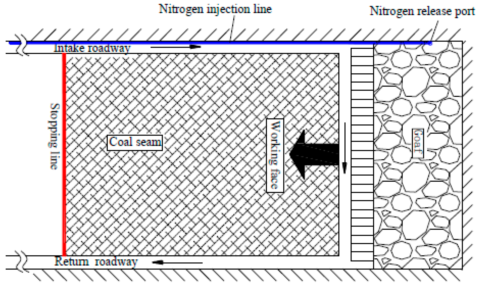
Figure 1. Open buried pipe nitrogen injection process.
Fire 06 00363 g001
Figure 2. Full cross-section nitrogen curtain injection process.
Fire 06 00363 g002
Figure 3. Nitrogen-injecting curtain stereo effect.
Fire 06 00363 g003
Figure 4. Nitrogen release hole group distribution.
Fire 06 00363 g004
Figure 5. Sketch map of full cross-section nitrogen curtain layout.
Fire 06 00363 g005
Figure 6. Layout of the monitoring points at the rear of the bracket.
Fire 06 00363 g006
Figure 7. Oxygen concentration change in the goaf.
Fire 06 00363 g007
Figure 8. Distribution of oxidation zone in the goaf.
Fire 06 00363 g008
Figure 9. The change in upper corner CO concentration.
Fire 06 00363 g009
Figure 10. The change in lower corner CO concentration.
Fire 06 00363 g010
Figure 11. Inerting efficiency in upper corner of the working face.
Fire 06 00363 g011
Figure 12. Inerting efficiency in lower corner of the working face.
Fire 06 00363 g012
Disclaimer/Publisher’s Note: The statements, opinions and data contained in all publications are solely those of the individual author(s) and contributor(s) and not of MDPI and/or the editor(s). MDPI and/or the editor(s) disclaim responsibility for any injury to people or property resulting from any ideas, methods, instructions or products referred to in the content.