Abstract
Passive explosion-isolation facilities in underground coal mines, such as explosion-proof water troughs and bags, face challenges aligned with current trends in intelligent and unmanned technologies, due to restricted applicability and structural features. Grounded in the propagation laws and disaster mechanisms of gas explosions, the device in this paper enables accurate identification of explosion flames and pressure information. Utilizing a high-speed processor for rapid logical processing enables judgments within 1 ms. Graded activation of the operating mechanism is enabled by the device. The tunnel flame-proof device’s flame-extinguishing agent has a continuous action time of 6075 ms. Experiments on the active flame-proof effect of a 100 m3 gas explosion were conducted using a cross-sectional 7.2 m2 large-tunnel test system. With a dosage of 5.6 kg/m2, the powder flame-extinguishing agent completely extinguished the explosion flame within a 20 m range behind the explosion isolator. Numerical calculations unveiled the gas-phase chemical suppression mechanism of the powder flame-extinguishing agent NH4H2PO4 in suppressing methane explosions. Building upon these findings, application technology for active flame-proofing was developed, offering technical support for intelligent prevention and control of gas explosions in underground coal mines.
1. Introduction
Coal stands as a cornerstone of China’s energy landscape, contributing coal production of 4.56 billion tons in 2022, according to the China Coal Industry Economic Operation Report 2022. Despite advancements in alternative energy sources, coal consumption continues to hold a significant share [1,2]. The intricate nature of coal endowment conditions, coupled with the potential for disasters [3,4], means that gas explosions in coal mines can unleash high temperatures, intense pressures, shockwaves, and toxic gases. The repercussions of such explosions are profound, leading to substantial casualties and colossal economic losses [5,6]. Between 2007 and 2019, Chinese coal mines experienced a staggering total of 456 gas-related accidents, resulting in 2112 fatalities. Of these incidents, 223 were classified as gas explosion accidents. This alarming data underscore the persistently severe challenges facing coal mine safety in relation to production [7,8].
Presently, passive explosion-isolation technologies are widely employed in underground coal mines. These technologies leverage the temporal discrepancy between the explosion shockwave and the advancing flame front during the explosion propagation process. Utilizing the shockwave as a triggering force, passive explosion-isolation facilities, including rock powder sheds, explosion-isolation water troughs, and explosion-isolation water bags, create a suppression zone ahead of the flame, halting the further spread of the explosion. The effectiveness of passive explosion-isolation technology facilities depends on various factors, such as installation location and explosion energy. However, their activation often lacks synchronization with the arrival of the explosion flame, and the short-lived explosion-isolation water curtain limits their performance. Additionally, these facilities are typically disposable, rendering them ineffective in the face of secondary or multiple explosions within a coal mine [9,10]. The operational range of passive explosion-isolation facilities typically spans 60 to 140 m from the explosion source. Furthermore, facilities like explosion-isolation water sheds necessitate regular watering for dust removal and frequent relocation, resulting in a substantial daily maintenance workload. Given their structural limitations and on-site applicability, these facilities struggle to meet the evolving demands of intelligent and unmanned coal mining practices.
Due to inherent limitations in technical performance, daily management, and maintenance of passive explosion-isolation facilities, there are constraints on their effectiveness in isolating explosions. In recent years, active explosion-isolation technologies, exemplified by automatic fine water mist explosion-isolation systems [11,12] and automatic powder spray explosion-isolation systems [13,14,15], have garnered significant attention. Active flame-proof technology proves instrumental in effectively isolating secondary or multiple gas explosions. Shao et al. [16,17] devised a vacuum chamber installed on one side of an experimental pipeline. In the event of a gas explosion, the negative pressure inside the vacuum chamber draws in the flame and shockwave, thereby mitigating the explosion shockwave and suppressing the flame’s propagation. Jiang et al. [18] developed an automatic spraying system employing nitrogen and ABC powder to suppress gas explosions. Lu et al. [19] engineered integrated equipment that automatically detects flames and dispenses suppressants, evaluating the suppressive effects of active flame-proof devices positioned at various ventilation points during gas explosions. Cui et al. [20] created equipment involving a vacuum chamber coupled with CO2. The injection of CO2 into the vacuum chamber enhances the suppressive effect of an active flame-proof device on gas explosions, reducing the cost of maintaining high vacuum levels.
The previous studies predominantly focused on a flame-proof device that suppresses the spread of gas explosion flames, with a limited exploration into flame detection. Active flame-proof technology should comprehensively employ sensors to collect explosion information. It utilizes a control system to guide the injection system in creating explosion suppression zones, demonstrating the capability to suppress many explosions, demanding high system stability. Therefore, a comprehensive active flame-proof device that combines flame detection and explosion suppression is crucial for coal mine safety. To effectively advance the intelligent prevention and control of gas and coal-dust explosions in coal mines, and to promote practical engineering applications, this study applies the large underground tunnel test system of the Chongqing Research Institute of China Coal Technology and Engineering Group Corporation. Combining the requirements of intelligent coal mining construction, an intelligent active flame-proof device was developed. The study investigates the dosage and application technology of powder flame-extinguishing agents under different explosion conditions, providing important theoretical and technical support for the intelligent control of gas and coal-dust explosions in underground coal mines. Additionally, through numerical calculations, the study reveals the gas-phase chemical suppression mechanism of the flame suppressant NH4H2PO4 powder in suppressing methane explosions. The proposed application technology of active flame-proof devices contributes significantly to the intelligent management of gas and coal-dust explosions in underground coal mines.
2. Principles of Active Flame-Proof Technology
An active flame-proof device typically encompasses flame sensors, pressure sensors, controllers, tunnel isolators, and power sources, as depicted in Figure 1. The operational principle involves advanced detection of explosion flames and pressure information, following an explosion incident. The controller promptly triggers the isolator’s activation, initiating the release of powder flame-extinguishing agents to create an explosion-isolation barrier, covering a specific area. This action extinguishes the explosion flames, mitigates the explosion pressure waves, and hinders the further spread of the explosion.

Figure 1.
Diagram of the active flameproof device.
By considering the positional relationship and characteristic changes in flames and pressure waves during various stages of explosion propagation, a comprehensive detection and analysis of the explosion flame and pressure information is carried out. This leads to the graded activation of different quantities of isolators. The explosion-isolation effectiveness of active-isolation devices is influenced by the cross-sectional dimensions of the tunnel, the location of potential explosion sources, and the explosive equivalent. In light of these conditions, the technical indicators of the isolator, the powder mass concentration of the flame-extinguishing agent, and the installation position, emerge as direct factors influencing the explosion-isolation effectiveness. They are also pivotal elements in the application technology of active flame-proof devices.
3. Experimental Setup
3.1. Flame and Pressure Sensors
To mitigate false triggering caused by sunlight in the ultraviolet wavelength band and underground mining lights, the flame sensor utilizes a narrow-band spectrum with a spectral response range of 185 to 260 nm. The flame sensor circuit incorporates background light detection. Through an intelligent analysis of light intensity and filtering, it can effectively differentiate between explosion flames and ambient light sources. Additionally, the two ultraviolet photosensitive elements operate in an AND relationship, ensuring high reliability. The high frequency of ultraviolet light enables swift detection in the early stages of a flame, resulting in a rapid response time. The duration from the sensor receiving the flame signal to outputting the electrical signal is within 1 ms.
The pressure sensor employs a pressure-resistant silicon crystal fabricated through MEMS processing for detecting pressure signals. This crystal is utilized to measure the dynamic pressure resulting from gas explosions. The upper-limit frequency response of dynamic pressure measurement is dependent on the design form and placement position of the diaphragm. Given the small mass of the silicon diaphragm, the frequency response exceeds 10 kHz, with a rapid sensor response time of 2 ms. The sensor circuit encompasses measurement components, signal amplification circuitry, A/D conversion circuitry, processing unit, control output, and other integral parts. It has a pressure-sensor activation threshold of 25 kPa. Flame and pressure sensors were shown in Figure 2.
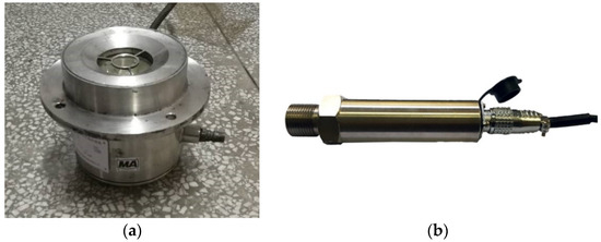
Figure 2.
(a) flame sensor (b) pressure sensor.
3.2. Graded Start Controller for Active Flame Proofing
The controller serves as the central component of the tunnel explosion-isolation device, exerting a pivotal influence on the execution and effectiveness of explosion-isolation actions. As illustrated in Figure 3, it receives detection signals from the sensors, scrutinizes and evaluates the information, and generates control signals to initiate the isolator’s action. The controller can connect to, and power, two flame sensors and two pressure sensors. It monitors the operational status of each flame sensor and pressure sensor, while concurrently receiving signals from multiple flame and pressure sensors. Intelligently designed, the controller boasts features such as automatic fault diagnosis, automatic sensor and isolator detection, power supply monitoring, and prompt information-transmission functions. The controller adheres to communication protocols to both receive and provide feedback on relevant data, offering real-time insights into the system’s operational status, to a remote terminal. Equipped with a high-speed processor, the controller conducts logical processing, intelligently and precisely identifying flame and pressure signals, and rendering logical judgments within 1 ms. Based on the laws governing flame and pressure propagation during explosions, the controller can establish distinct triggering thresholds for pressure sensors. By considering the detected location and pressure magnitude of the flame and pressure signals, it achieves “stepwise control, multi-level activation”. The controller also stores triggering information and displays status indications on the screen.

Figure 3.
The controller.
3.3. Tunnel Isolator
The tunnel isolator serves as the central element of the tunnel explosion-isolation device, predominantly comprised of a tank body, a rapid opening structure, spray pipelines, and a powder spraying mechanism, as illustrated in Figure 4. Operating on the principle of stored pressure, the isolator stores powder flame-extinguishing agents and high-pressure inert gas, functioning as the terminal execution mechanism to isolate gas explosions within the tunnel. The isolator’s tank body adopts a standard high-pressure vessel structure, featuring a design with a large-capacity storage unit that can accommodate 30 kg of powder. It utilizes high-pressure nitrogen gas as the driving force, operating at a pressure of 8.0 ± 1.0 MPa, and holds an IP65 protection rating. The rapid-opening mechanism of the isolator employs an electronic trigger to rupture the diaphragm, enabling the isolator opening valve to swiftly open within 2 ms. This establishes a two-phase explosion-isolation barrier comprised of gas and powder, substantially amplifying the efficacy of explosion isolation.
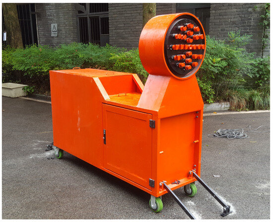
Figure 4.
The active flame-proof device.
The dispersion characteristics of the sprayed flame-extinguishing agent in space significantly influence the ultimate explosion-isolation effectiveness of the isolator. To assess the spraying effect of the tunnel isolator, high-speed camera technology was employed, with a capture frame rate of 1000 fps. The spraying experiment utilized a simulated signal to trigger the opening mechanism, acting as the starting point for action control. The final configuration of the powder spraying mechanism was determined by adjusting the nozzle angle, quantity, and distribution method. Through image analysis, the lag time, fogging time, and duration of action of the isolator were determined. According to the test results, the powder flame-extinguishing agent is rapidly sprayed under high-pressure driving, forming a cone-shaped cloud with an initial area of 8.04 m2 within the first 120 ms. It propels forward rapidly, while simultaneously diffusing radially. The effective spraying distance can reach up to 30 m, and the effective action time of the extinguishing agent in space extends to 6075 ms. The effect of the powder cloud in the spraying experiment is depicted in Figure 5.

Figure 5.
Distribution of cloud curtain of powders.
3.4. Experimental System and Methodology
The experimental tests were conducted to assess the effectiveness of flame-extinguishing agents in isolating explosion propagation under varying gas explosion intensity conditions. These experiments were performed using an engineering-scale large underground-explosion tunnel test system. The experimental system consists primarily of a 7.2 m2 cross-sectional underground experimental tunnel, an explosion data acquisition system, a gas-distribution and circulation system, an ignition device, and a hydraulic system. By adjusting conditions such as the length of the gas chamber, the system can facilitate gas explosion propagation and isolation experiments on a realistic scale. The system arrangement is depicted in Figure 6.
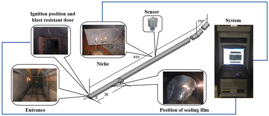
Figure 6.
Layout of the large laneway test system.
The underground experimental tunnel spans a total length of 896 m, with the main section designated for explosion testing extending to 710 m. The cross-section exhibits a semi-circular arch shape, featuring both flat and inclined sections with a 24° slope. Double explosion-proof doors are positioned at the ends of two ignition chambers. The closure of these doors divides the tunnel into a closed section and an open section. Sealing rings for closed sections are strategically placed at intervals of 4.15 m, 7 m, 14 m, and 28 m, starting from the closed end of the tunnel. By sealing these points with plastic film, gas explosion chambers of four distinct capacities (30 m3, 50 m3, 100 m3, and 200 m3) can be configured. For the initial 40 m from the starting end, measurement points along the tunnel walls are spaced at 10 m intervals. Beyond the 40 m mark, measurement points are set at intervals of 20 m. The arrangement of sensors within the tunnel is illustrated in Figure 7.
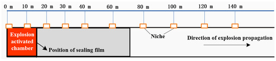
Figure 7.
Schematic diagram showing the layout of instrument niches.
Utilizing the experimental system, simulations were executed to assess the explosion-isolation capabilities for both a 100 m3 gas explosion and a 100 m3 gas explosion, each subjected to varying mass concentrations of powder flame-extinguishing agents. The experiments emphasized the critical need to establish an effective explosion-isolation barrier before the explosion flame reached the specified point. Consequently, the controller was configured to trigger the tunnel isolator’s spray mechanism, simultaneously with the initiation of the explosion experiment. The isolation experiments employed ABC ultrafine dry powder as the flame-extinguishing agent, with its primary component being NH4H2PO4. Variations in explosion-isolation effectiveness were explored by adjusting the powder filling amount or the number of isolators to modify the extinguishing agent usage. Preceding the experiment, gas was introduced into the gas explosion chamber, via an inflation pipeline, generating a gas–air explosive mixture, through circulation. In both the explosion and isolation experiments, an igniter was employed to ignite the gas mixture. Synchronous data collection of the explosion flame’s propagation speed and range during the experiment was conducted, using the PXIe signal processing module, featuring multiple channels and a sampling rate of 1 million samples per second. To evaluate the performance and effectiveness of the isolation device under different explosion intensity conditions, the tunnel isolator was positioned at the front end, where the maximum gas explosion pressure and maximum flame speed occurred. This setup allowed for a comparative analysis with the explosion characteristic values observed in experiments with equivalent propagation. In the 100 m3 gas explosion-isolation experiment, the tunnel isolator was installed within the range of 12–15 m from the closed end inside the main tunnel, based on the results of explosion propagation experiments.
At a position 14 m from the closed end of the tunnel, a volume of 100 m3 was isolated using a membrane as the ignition chamber. At a position 12–15 m from the closed end, an explosion-isolation device was installed. Three different quantities of ABC powder suppressors, specifically 20 kg, 30 kg, and 40 kg, were chosen for suppression tests. The corresponding mass densities of the suppressors are approximately 2.8 kg/m2, 4.2 kg/m2, and 5.6 kg/m2, respectively.
3.5. Numerical Calculations
CHEMKIN-PRO was studied for the gas-phase chemical suppression mechanism of NH4H2PO4 in suppressing methane explosions. The chemical reactions of CH4/air were modeled using the GRI-Mech 3.0 model. The NH4H2PO4 powder completely decomposes into gaseous substances NH3 and H3PO4 in the flame preheating zone. The mechanism model for phosphorus-containing substances involving H3PO4 is based on the research data of Pitz et al. [21], Twarowski [22], and Korobeinichev et al. [23]. The mechanism model for nitrogen-containing substances involving NH3 is based on the research data of Konnov [24] and Li et al. [25]. These mechanism models collectively encompass 86 species and 573 reactions. A Closed 0–D Homogeneous batch reactor was employed, with a constrained volume and energy-solution equation approach. The reactor volume was set at 100 m3, the initial temperature at 1200 K, and the ambient pressure at 1 atm. Methane was used as a substitute for gas during numerical calculations, considering that methane is the primary component of the gas.
4. Results and Discussion
4.1. Gas-Explosion-Flame Velocity and Pressure
The progression of the explosion flame serves as a direct indicator of the explosion’s intensity and hazard, offering a visual representation of the destructive energy unleashed by the explosion. Concurrently, the explosion pressure stands as a pivotal parameter for gauging the reaction process and the extent of damage caused by the explosion. To quantify the average speed of flame propagation between two adjacent measurement points, the calculated arrival times of the explosion flame at various measurement locations and the extent of flame coverage in explosion tests are instrumental. The determination can be expressed as follows:
v = L/(t2 − t1)
In a 7.2 m2 large underground experimental tunnel, a gas explosion with a volume fraction of 9.5 vol% in a 100 m3 chamber was simulated. Figure 8 depicts the changes in flame speed and explosion pressure in relation to propagation distance.
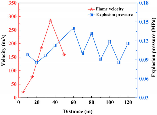
Figure 8.
Flame velocity and explosion pressure for gas explosion.
Examining the graph, it is evident that the maximum explosion pressure at various measurement points does not consistently decrease with the increasing propagation distance of the gas explosion. Near the explosion source, combustible gas ignites, initiating the rapid outward expansion of the explosion wave from the point source. The gas moves forward under the influence of the compression wave, reaching a peak pressure before diminishing. Due to the spatial constraints of the tunnel and the forward progression of the explosion wave, more gas undergoes ignition, resulting in a rapid increase in explosion pressure. As the explosion reaction proceeds and no additional gas participates in the reaction, under unchanged conditions, the subsequent explosion pressures at various measurement points gradually decrease. During the 100 m3 gas explosion process, the maximum explosion pressure occurs at the 60 m measurement point, reaching 0.14 MPa. In the initial stage of the explosion, the flame-propagation speed exceeds the expansion speed of the pressure wave. As the explosion unfolds, a plane pressure wave forms, surpassing the flame front, creating a typical “two waves, three zones” structure. In the gas explosion experiment, influenced by the volume of combustible gas, the range covered by the explosion flame is 60 m. This aligns with the understanding that the length of the explosion flame zone is 3–5 times the initial gas accumulation area. The maximum flame-propagation speed generally corresponds to the region with the maximum explosion pressure, occurring in the range of 30 m to 40 m, with a peak value of 285.7 m/s. Beyond 60 m, the explosion pressure continues to propagate, but no explosion flame is detected.
4.2. Impact of Flame Suppressants on Gas-Explosion-Flame Velocity
At a gas volume fraction of 9.5 vol%, Figure 9 illustrates the variations in explosion- flame arrival positions and propagation speeds of a 100 m3 gas explosion, influenced by different quantities of ABC powder flame suppressant.
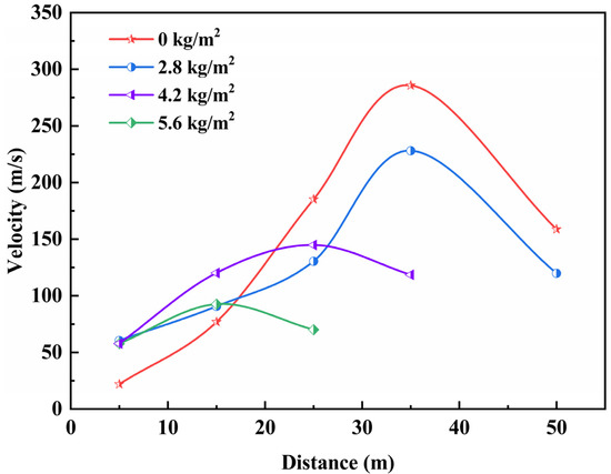
Figure 9.
Variation of flame propagation in 100 m3 gas flameproof experiments.
When the energy released by the combustion explosion surpasses the heat consumed and lost during the action of the suppressors, the explosion persists. In the explosion-isolation experiment, the tunnel explosion-isolation device sprayed ABC powder suppressors, to create an effective explosion-isolation barrier, extinguishing the flames. With the active flame-proof device in place, there exists a buffer zone for the explosion flame under the impact of the explosion pressure, leading to a notable reduction in both flame area and speed. However, at lower concentrations of ABC powder suppressors, the explosion-isolation barrier fails to effectively extinguish the flames. As the concentration of the flame suppressant increases, the explosion-isolation effect improves. In the explosion-propagation experiment, the flame range of a single 100 m3 gas explosion, with a volume fraction of 9.5 vol%, is 50 m. In the 100 m3 gas explosion-isolation experiment, when the powder mass is 40 kg (with a concentration of 5.6 kg/m2), the maximum flame speed shifts from the 30–40 m range to the 10–20 m range, with the maximum value decreasing from 285.7 m/s to 92.6 m/s, with the maximum decrease in flame speed being 67.59%. The explosion flame is completely extinguished within 20 m behind the explosion-isolation device. Based on the analysis of the explosion-isolation experiment results, the active flame-proof device promptly detects explosion flame and pressure information, acts in the early stages of the explosion, and has a prolonged duration of action, effectively impeding the propagation of gas explosion flames. In the explosion-isolation experiment, when the mass concentration of ABC powder suppressors reaches a certain level, it reduces the thermal effect, leading to the extinguishing of the explosion flame.
4.3. Impact of Flame Suppressants on Gas Explosion Pressure
Figure 10 depicts the fluctuation in maximum explosion pressure in relation to propagation distance in gas explosion-isolation experiments, under different concentrations of powder media.
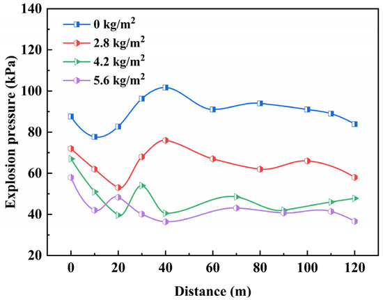
Figure 10.
Effects on explosion pressure under different concentrations of powders.
From the graph, it is evident that the application of ABC powder suppressors effectively mitigates the peak explosion pressure. In all three sets of suppression experiments, the maximum explosion pressures at various distances exhibit varying degrees of reduction, indicating the suppression effect of ABC powder suppressors on gas explosions. Notably, in suppression experiments with different mass densities, there is a discernible difference in the attenuation of peak pressures, at various distances. Specifically, as the powder-mass density increases, the degree of attenuation of peak pressure continues to rise. Although the active flame-proof system cannot eliminate the explosion pressure wave, it significantly diminishes its intensity and destructiveness. In the gas explosion-isolation experiment, when the powder concentration is 2.8 kg/m2, the maximum explosion pressure decreases, and the explosion overpressure at the same location is reduced by 25%, indicating a certain suppression effect on the explosion. As the powder concentration increases, the isolation system’s effectiveness in reducing the shock wave gradually intensifies. When the powder concentration is 4.2 kg/m2 and 5.6 kg/m2, the maximum explosion pressure occurs near the explosion source, and the peak pressures at various distances behind the isolation device remain below 60 kPa, throughout the explosion process. Along the tunnel, they exhibit a gradual attenuation trend. The maximum explosion pressure at the rear of the isolation system decreases to 40.5 kPa and 36.4 kPa, respectively, representing a reduction of 60.2% and 64.2%, compared to the maximum pressure at the same location in the experiment without the isolation device.
4.4. Gas-Phase Chemical-Suppression Mechanism of Ammonium Dihydrogen Phosphate on Methane Explosions
In the process of methane explosions, chain reactions in chemical reactions are primarily driven by free radicals O, H, and OH. The chemical reaction rates of these free radicals determine the propagation speed and severity of the explosion flame [26,27]. Preventing the ignition process can help avoid certain accidents. Figure 11 illustrates the molar fraction changes of CH4, O2, CO2, H2O, H, O, OH, and CO after the explosion of 9.5 vol% methane. The concentrations of H, O, OH, and CO exhibit abrupt peaks, indicating the generation of a large number of free radicals in the initial reaction stage. Subsequent chain reactions consume some of these free radicals, leading to a decrease in their concentrations. Figure 12 shows the impact of 5.6 kg/m2 NH4H2PO4 powder on the molar fractions of various components in a 9.5 vol% methane explosion. The addition of the flame suppressant results in a reduction in the molar fractions of CO and CO2.
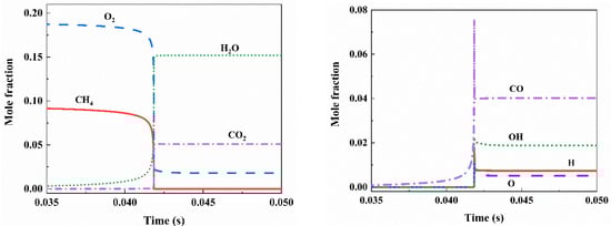
Figure 11.
Variation of mole fraction of components in 9.5 vol% methane explosion.
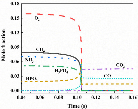
Figure 12.
A total of 5.6 kg/m2 NH4H2PO4 inhibits the change in mole fraction of each component in 9.5 vol% methane explosion.
Known to play a crucial supporting role in flame development, H, O, and OH undergo significant changes in their molar fractions upon the addition of NH4H2PO4 powder at different concentrations, as depicted in Figure 13. Following the introduction of the flame-suppressant NH4H2PO4 powder, the concentrations of the three free radicals—H, O, and OH—markedly decreased. NH4H2PO4 exhibits effective clearance effects on these three free radicals, contributing to the suppression and development of the flame.
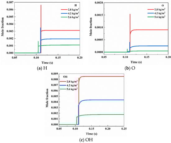
Figure 13.
Effects of NH4H2PO4 on H, O, and OH at different concentrations.
The key intermediate product yields in NH4H2PO4 powder suppressing methane explosions are illustrated in Figure 14. The reactions depicted in the figure play a crucial role in eliminating the free radicals H, O, and OH. These reactions consist of three groups, forming a catalytic cycle:
PO2 + H + M = HOPO + M
HOPO + OH = PO2 + H2O
HOPO + O = OH + PO2
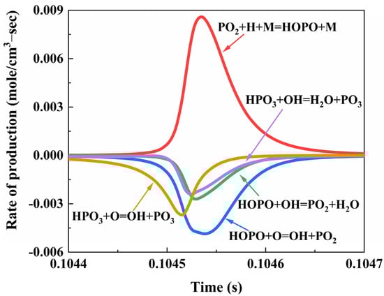
Figure 14.
Rate of production of P due to reactions in CH4/NH4H2PO4/air flame.
This catalytic cycle continuously catalyzes the consumption and generation of crucial intermediate products, PO2 and HOPO, derived from the decomposition of the flame suppressant NH4H2PO4, forming a reversible reaction PO2 ⇔ HOPO. Additionally, the critical intermediate product HPO3 generated from the decomposition of NH4H2PO4 combines with free radicals O and OH to produce H2O and PO3:
HPO3 + OH = H2O + PO3
HPO3 + O = OH + PO3
These two reactions convert highly reactive O and OH into stable combustion products, H2O, and other free radicals, which are less relevant to the chain reactions of methane, playing a role in terminating the chain reactions. The catalytic recombination of these critical intermediate products and the removal of key free radicals result in a reduction in the quantities of free radicals H, O, and OH, leading to a decrease in chain branching and a reduction in heat release. The decomposition of the flame suppressant NH4H2PO4, producing NH3, consumes O2, to generate H2O and N2, thereby reducing the concentration of O2 within a unit volume and decreasing the collision probability between CH4 and O2 and O free radicals.
5. Application Technology of Active Flame-Proof Devices
In compliance with the stipulations outlined in the ‘Coal Mine Safety Regulations’ and based on a comprehensive analysis of the risks associated with gas explosions in underground coal mines, it is imperative to install explosion-proof devices in areas susceptible to explosions. These areas encompass coal galleries, semi-coal–rock galleries in the advancing working face, intake and return air-tunnels in the coal mining face, adjacent coal mining faces, adjacent mining areas, and connecting tunnels.
The active flame-proof device, designed for proactive detection and precise control of explosion incidents, finds applicability in locations within underground coal mines prone to the risk of gas or coal-dust explosions. It promptly extinguishes explosion flames following an eruption, thereby mitigating the severity of the accident. During on-site implementation, the design considerations should revolve around the shape and dimensions of the tunnel section, potential sources of explosion, and explosion equivalents. This determination is crucial for establishing the optimal number and placement of explosion-isolation devices. The quantity of powder flame suppressant must be computed based on the tunnel section’s area. For effectively isolating gas explosions, the required quantity of flame suppressant should exceed 1.5 times the unit quantity derived from type testing of the active flame-proof device, multiplied by the tunnel section’s area, as per Equation (2).
In the equation: m—the required quantity of flame suppressant for isolating gas explosions, kg; c—the unit-area quantity of flame suppressant determined in the inspection of the tunnel explosion-isolation device, kg/m2; and S—the area of the tunnel section, m2.
During on-site application, the flame and pressure sensors of the active flame-proof device must feature anti-pollution measures on their windows or probes, with these elements oriented toward potential hazard sources. The flame sensor should be positioned within 5 m of the potential explosion source. Installation of the tunnel explosion-isolation device should not disrupt normal tunnel operation. The isolator nozzles should be directed toward the hazard source, and the on-site configuration must guarantee that the emitted mist from the flame-suppressant spray effectively covers either the potential hazard source or the entire cross-section of the tunnel.
When deploying an active flame-proof device in a coal mine’s explosive hazard tunnel, a system of active flame-proof devices should be installed in the straight tunnel, within a 200 m range behind the suppression device. Moreover, at intersections, changes in slope and turns in other tunnels susceptible to gas and coal-dust explosions, a system of active flame-proof devices should be installed in the straight tunnel within a 60 m range from the high-risk point.
6. Conclusions
This study conducted independent research into, and the development of, an active flame-proof device and gas explosion isolation. The key findings are as follows:
- We developed an active flame-proof device with flame and pressure sensors, a start controller, and tunnel explosion isolators. The device uses spectral recognition and dual ultraviolet sensors for flame detection, and pressure-resistant silicon crystal components for precise identification. The controller makes rapid decisions within 1 ms, allowing for graded activation. The tunnel explosion isolator has large-capacity storage and efficient spraying, for a continuous action time of up to 6075 ms.
- We conducted experiments on 100 m3 gas explosions to evaluate the effectiveness of a powder flame-extinguishing agent. The explosion barrier significantly reduce the flame-propagation range, effectively stopping its spread within a 20 m range behind the isolation device.
- We investigated the gas-phase chemical-suppression mechanism of NH4H2PO4 in suppressing methane explosions. The flame suppressant’s intermediate products play a significant role in eliminating free radicals, reducing chain branching, and in heat release.
- We formulated an application technology for active flame-proof devices in underground coal mines. Guidelines for device installation, calculation of extinguishing agent dosage, and determination of protective zone range were established, supporting intelligent explosion prevention and control.
Author Contributions
Conceptualization, Z.H. and R.S.; methodology, G.W.; software, S.J.; validation, Z.H. and S.X.; formal analysis, G.W.; data curation, Z.H.; writing—original draft preparation, Z.H.; writing—review and editing, R.S.; project administration, Z.H., R.S. and G.W. All authors have read and agreed to the published version of the manuscript.
Funding
This research was funded by the National Nature Science Foundation of China (52104238, 52174226, and 52174227) the Natural Science Foundation of Chongqing, China (CSTB2022NSCQ-MSX0867), and the grants from the State Key Laboratory of Gas Disaster Detecting, Preventing and Emergency Controlling (2022SKLKF03).
Institutional Review Board Statement
Not applicable.
Informed Consent Statement
Not applicable.
Data Availability Statement
Data available on request, due to restrictions.
Conflicts of Interest
The authors declare no conflict of interest.
References
- Teng, J.; Li, S.; Jia, M.; Lian, J.; Liu, H.; Liu, G.; Wang, W.; Volker, S.; Feng, L.; Yao, X.; et al. Research and application of in-seam seismic survey technology for disaster-causing potential geology anomalous body in coal seam. Acta Geol. Sin. Engl. Ed. 2020, 94, 10–26. [Google Scholar] [CrossRef]
- Wang, Q.; Lu, X.; Ma, C.; Luo, Z.; Li, Q.; Deng, J.; Sheng, Y.; Peng, B. Comparative study of the kinetic characteristics of coal spontaneous combustion. J. Therm. Anal. Calorim. 2023, 148, 4463–4476. [Google Scholar] [CrossRef]
- Meng, X.; Liu, Q.; Luo, X.; Zhou, X. Risk assessment of the unsafe behaviours of humans in fatal gas explosion accidents in China’s underground coal mines. J. Clean. Prod. 2019, 210, 970–976. [Google Scholar] [CrossRef]
- Cheng, C.; Si, R.; Wang, L.; Jia, Q.; Xin, C. Explosion and explosion suppression of gas/deposited coal dust in a realistic environment. Fuel 2024, 357, 129710. [Google Scholar] [CrossRef]
- Lin, C.L.; Chien, C.F. Systems thinking in a gas explosion accident–lessons learned from Taiwan. J. Loss Prev. Process Ind. 2019, 62, 103987. [Google Scholar] [CrossRef]
- Wang, K.; Jiang, S.; Ma, X.; Wu, Z.; Zhang, W.; Shao, H. Study of the destruction of ventilation systems in coal mines due to gas explosions. Powder Technol. 2015, 286, 401–411. [Google Scholar] [CrossRef]
- Zhang, J.; Xu, K.; Reniers, G.; You, G. Statistical analysis the characteristics of extraordinarily severe coal mine accidents (ESCMAs) in China from 1950 to 2018. Process Saf. Environ. Prot. 2020, 133, 332–340. [Google Scholar] [CrossRef]
- Zhang, J.; Fu, J.; Hao, H.; Fu, G.; Nie, F.; Zhang, W. Root causes of coal mine accidents: Characteristics of safety culture deficiencies based on accident statistics. Process Saf. Environ. Prot. 2020, 136, 78–91. [Google Scholar] [CrossRef]
- Liu, W.; Mu, C.; Li, Z. Influence of cavity structure on gas explosion characteristics in coal mine. Powder Technol. 2022, 398, 117084. [Google Scholar] [CrossRef]
- Cao, X.; Wang, C.; Wang, Y.; Wang, Z.; Wei, H.; Lu, Y. Research on the inhibition characteristics of ultrafine water mist on gas/dust two-phase mixture explosions. Fuel 2024, 357, 129967. [Google Scholar] [CrossRef]
- Yang, K.; Zhang, P.; Yue, C.; Chen, K.; Ji, H.; Xing, Z.; Hao, Y.; Jiang, J. Experimental research on methane/air explosion inhibition using ultrafine water mist containing methane oxidizing bacteria. J. Loss Prev. Process Ind. 2020, 67, 104256. [Google Scholar] [CrossRef]
- Song, Y.; Zhang, Q. Quantitative research on gas explosion inhibition by water mist. J. Hazard. Mater. 2019, 363, 16–25. [Google Scholar] [CrossRef] [PubMed]
- Luo, Z.; Wang, T.; Tian, Z.; Cheng, F.; Deng, J.; Zhang, Y. Experimental study on the suppression of gas explosion using the gas–solid suppressant of CO2/ABC powder. J. Loss Prev. Process Ind. 2014, 30, 17–23. [Google Scholar] [CrossRef]
- Song, Y.; Zhang, Q. The quantitative studies on gas explosion suppression by an inert rock dust deposit. J. Hazard. Mater. 2018, 353, 62–69. [Google Scholar] [CrossRef]
- Zhao, T.; Chen, X.; Luo, Z.; Cheng, F.; Lu, K.; Shi, X.; Yu, W. Effect of N2 inerting on the inhibition of methane explosions by a multicomponent powder. Fuel 2023, 337, 127203. [Google Scholar] [CrossRef]
- Shao, H.; Jiang, S.; Zhang, X.; Wu, Z.; Wang, K.; Zhang, W. Influence of vacuum degree on the effect of gas explosion suppression by vacuum chamber. J. Loss Prev. Process Ind. 2015, 38, 214–223. [Google Scholar] [CrossRef]
- Shao, H.; Jiang, S.; Wu, Z.; Zhang, W.; Wang, K. Influence of diaphragm thickness on gas explosion suppression by vacuum chamber. Powder Technol. 2016, 295, 245–253. [Google Scholar] [CrossRef]
- Jiang, B.; Liu, Z.; Tang, M.; Yang, K.; Lv, P.; Lin, B. Active suppression of premixed methane/air explosion propagation by non-premixed suppressant with nitrogen and ABC powder in a semi-confined duct. J. Nat. Gas Sci. Eng. 2016, 29, 141–149. [Google Scholar] [CrossRef]
- Lu, C.; Zhang, Y.; Zhu, H.; Meng, Q.; Pan, R.; Yu, M. Spurting NH4H2PO4 powder to prevent the propagation of gas explosion along the duct. Combust. Sci. Technol. 2021, 193, 2534–2552. [Google Scholar] [CrossRef]
- Cui, C.; Shao, H.; Jiang, S.; Zhang, X. Experimental study on gas explosion suppression by coupling CO2 to a vacuum chamber. Powder Technol. 2018, 335, 42–53. [Google Scholar] [CrossRef]
- Dounia, O.; Vermorel, O.; Poinsot, T. Theoretical analysis and simulation of methane/air flame inhibition by sodium bicarbonate particles. Combust. Flame 2018, 193, 313–326. [Google Scholar] [CrossRef]
- Twarowski, A. The temperature dependence of H + OH recombination in phosphorus oxide containing post-combustion gases. Combust. Flame 1996, 105, 407–413. [Google Scholar] [CrossRef]
- Korobeinichev, O.P.; Shvartsberg, V.M.; Shmakov, A.G.; Knyazkov, D.A.; Rybitskaya, I.V. Inhibition of atmospheric lean and rich CH4/O2/Ar flames by phosphorus-containing compound. Proc. Combust. Inst. 2007, 31, 2741–2748. [Google Scholar] [CrossRef]
- Konnov, A.A. Implementation of the NCN pathway of prompt-NO formation in the detailed reaction mechanism. Combust. Flame 2009, 156, 2093–2105. [Google Scholar] [CrossRef]
- Li, B.; He, Y.; Li, Z.; Konnov, A.A. Measurements of NO concentration in NH3-doped CH4+air flames using saturated laser-induced fluorescence and probe sampling. Combust. Flame 2013, 160, 40–46. [Google Scholar] [CrossRef]
- Zhang, Z.; Gao, W.; Jiang, H.; Bai, Q.; Zheng, G. Explosion mechanism of nano-sized dust cloud in interconnected vessels. Combust. Flame 2024, 259, 113135. [Google Scholar] [CrossRef]
- Nie, Z.; Gao, W.; Jiang, H.; Zhao, F.; Zheng, G.; Zhang, Z. Flameless venting characteristics of hydrogen explosion under the coupling of carbon dioxide and metal foam. Process Saf. Environ. Prot. 2023, 180, 375–385. [Google Scholar] [CrossRef]
Disclaimer/Publisher’s Note: The statements, opinions and data contained in all publications are solely those of the individual author(s) and contributor(s) and not of MDPI and/or the editor(s). MDPI and/or the editor(s) disclaim responsibility for any injury to people or property resulting from any ideas, methods, instructions or products referred to in the content. |
© 2023 by the authors. Licensee MDPI, Basel, Switzerland. This article is an open access article distributed under the terms and conditions of the Creative Commons Attribution (CC BY) license (https://creativecommons.org/licenses/by/4.0/).