Article

On The Flame Behavior during Cable Insulation Material Ignited by Fault Arc: A Flame Extracting and Noise Reduction Algorithm

1
State Key Laboratory of Fire Science, University of Science and Technology of China, Hefei 230027, China
2
Department of Architecture and Civil Engineering, City University of Hong Kong, Kowloon, Hong Kong, China
3
Center for Nature-Inspired Engineering, City University of Hong Kong, Kowloon, Hong Kong, China
*
Authors to whom correspondence should be addressed.
Submission received: 6 December 2022 / Revised: 14 January 2023 / Accepted: 20 January 2023 / Published: 24 January 2023

Abstract

:
The electric fault arc, particularly the series arc, leads to plenty of electrical fire. The limitations of t previous studies include: (1) most existing research focused on gaseous atmospheres rather than solids materials, which is contrary to the actual demand; and (2) the studied external heat sources were restricted to cone heaters and flames, while the electric arc was seldom studied. To overcome these limitations, we developed an experimental platform to investigate the flame behavior when cable insulation material was ignited by the fault arc. We proposed a flame-extracting and noise-reduction algorithm to process the enormous number of photos shot by the high-speed camera. The main obtained findings were: (1) the appropriate size of the structuring element plays an essential role in filtering the flame region in the photos, too small a size resulted in the wrong recognition of incandescent particles, while too large a size made a jagged distortion; (2) the mean flame area increased as the system load grew; (3) The flame size became more prominent, and the flame appeared more frequently in specific locations when the system load increased. The in-depth understanding of flame behavior provided by this work will help to optimize the design of electric systems and disaster prevention reduction.

1. Introduction

Unwanted or accidental fires can be initiated by electric currents, which are involved with the flow of energy [1]. According to the United States national fire statistics, 20% of structure fires can be attributed to electrical fires. The electric arc is one of the most critical factors causing electrical fire [2,3]. The electric arc can be divided into three categories: series arc, parallel arc, and arc to ground, according to their electrical characteristics [3]. Thanks to existing line protection devices, the parallel arc and the arc to the ground can be effectively detected and eliminated. Due to its extraordinarily high current characteristics, the parallel arc can be cut off in a timely manner from the fault circuit by the conventional circuit breaker. In addition, the arc to ground, due to its leakage current to the ground, can be effectively eliminated by the circuit breaker with residual current protection function installed at the main power line of residential buildings. However, present technical means to prevent the series arc still need to be improved. Therefore, the series arc comes first from a fire hazard perspective [4,5].
As stated in a recently published critical review paper [6], most existing research has focused on gaseous atmospheres as opposed to solid materials. Unfortunately, existing research is inverted regarding the actual need—many more fires occur where electrical failures ignite solid materials rather than gaseous atmospheres. The arc core temperature can reach up to 6500 K under 1A current in the air and increases with the increase of arc current. The ignition temperature of the vast majority of solid combustibles is lower than the arc core temperature [7]. Solid materials, including wood and carbon, ignited by the high-voltage electric arc have been investigated in previous studies [8,9,10,11,12,13,14]. The cable acts as the combustible material in numerous electrical fires. There are studies focusing on the external heat impact on cables, especially on a heat source such as the cone heater [15,16,17,18,19] and flame [20,21]. In addition to the cone heater and flame, an external electric arc can also serve as the heat source to ignite the nearby cables or other combustibles [7], which is crucial to understanding an electrical fire’s origin.
The series arc can lead to overheating and fire [22,23]. Some studies investigated the internal electric arc igniting electrical cables [3,24]. However, Takenaka et al. [24] and Moon et al. [3] used dry cotton as the combustible, which is much too conservative compared to using cable as the combustible. There indeed are some studies on arc formation due to overload in residential cables [25]. Nevertheless, the cable acts as both “perpetrator” and “victim”, where electric arc and ohmic heating are mixed, making the ignition mechanism chaotic. Therefore, to the authors’ best knowledge, the problem of electric wires being ignited by arcs in residential electricity scenarios is rarely studied.
An experimental platform was developed to improve the understanding of cable insulation material ignited by an external series arc. The electric arc generator was designed based on the UL 1699 standard [26]. The system voltage was set as 220V because this voltage is used in many regions of the world, such as China, Germany, Italy, Sweden, and the Netherlands. The ignition process was recorded by a high-speed camera, which is crucial to understand the fast change of flame behavior during the ignition process. We proposed a flame-extracting and noise-reduction algorithm to process the enormous number of photos shot by the high-speed camera. Image recognition technology has been widely used in electrical engineering [27,28] and fire science [29,30]. Compared with the commonly used flame identification algorithms in the field of fire, the algorithm proposed in this paper has been specially optimized according to the specific problems studied in this paper. The particularity of this problem includes: (a) the output of the high-speed camera is a grayscale image instead of an RGB color image, and the existing software is unsuitable to use directly; (b) the number of sampling frames must be high enough to capture the extremely unstable AC arc, resulting in a massive amount of raw data (about 80GB per experiment), which requires that the processing speed of this algorithm must be high enough; and (c) flames are accompanied by reflections from smoke and glowing incandescent spray particles, noise reduction is needed. The authors wrote a Python program in order to realize the above, particularly the functional requirements. In addition, the time evolution law of the size of the flame area under different system loads was calculated. This work provides essential support for evaluating the spatial impact range of flame results from cable insulation material ignited by an external series arc.

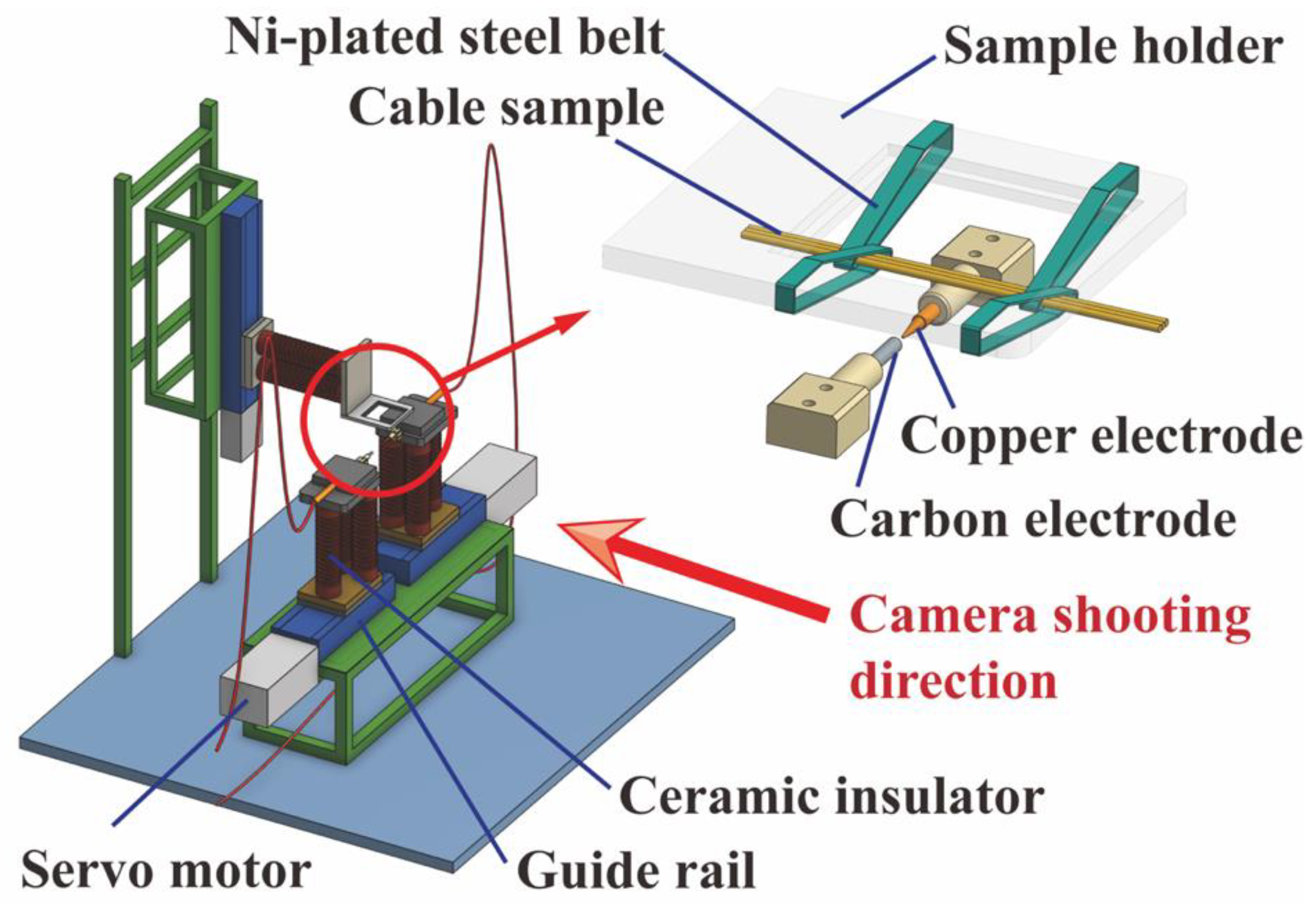
2. Experimental Setup and Methods

In this section, the procedure of obtaining high-speed photos is first introduced. Then, the image process algorithm’s implementation and the flame data extraction step are explained in detail. Finally, the noise-cleaning operation is described.

2.1. High-Speed Photos Acquisition

The experiment was conducted on an electric arc generator (see Figure 1), designed according to ANSI/UL 1699 standard. The outer diameter of both the copper electrode and the carbon electrode was 6 mm, and the tip length of the copper electrode was 0.7 inches. A couple of servo motors drove the electrodes to generate the electric arc. For the cable selected for this study, the PVC insulated 2.5 mm2 cable is commonly used in 220 V residential power supply. The cable sample used in this experiment was manufactured by Shanghai Qifan Cable Co., Ltd., Shanghai, China, which complies with GB/T5023.3-2008, and GB/T19666-2019 standards. The wire samples were made into a row of three, and the axial center was bent and hung 2 mm above the electrode without contacting any electrode. After the electric arc was initiated, the cable was heated and ignited. The high-speed camera was set in front of the arc generator, as shown in Figure 1.

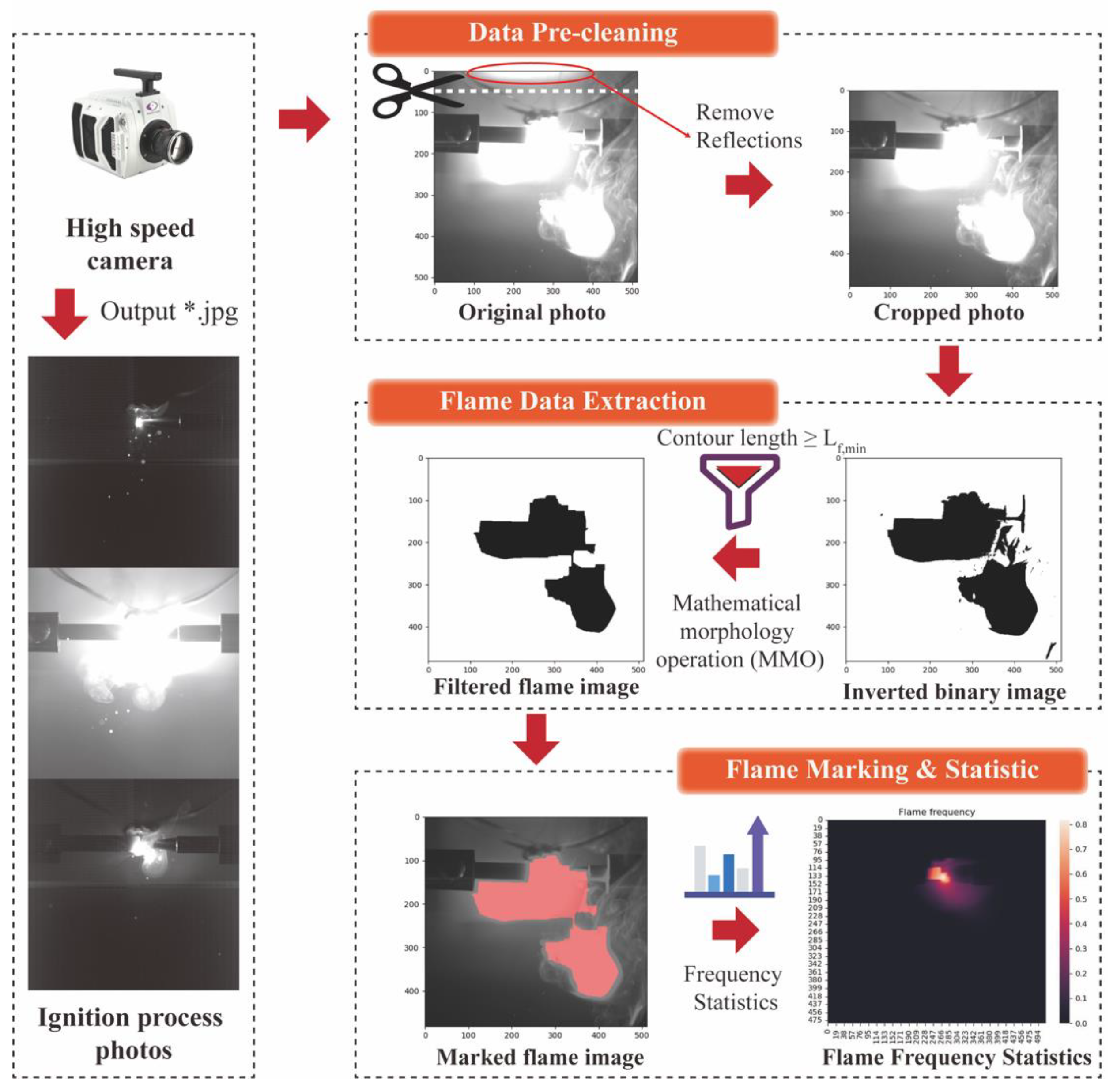
2.2. Image-Based Data Cleaning Algorithm Process

The process of the imaged-based flame detection and cleaning algorithm is shown in Figure 2. The three steps included, data pre-cleaning, flame data extraction, and flame marking & statistics.
Step 1: Pre-cleaning step
Crop the upper part (512 × 30) of the high-speed camera photo (512 × 512) to exclude reflections from the top wall of the stainless-steel experimental chamber.
Step 2: Flame data extraction
2-1 The pixel points in the cropped photo are plotted as the inverted binary image;
2-2 The image edge of the binary image is recognized according to the difference between the gray value of the flame and the particle and the gray value of the background;
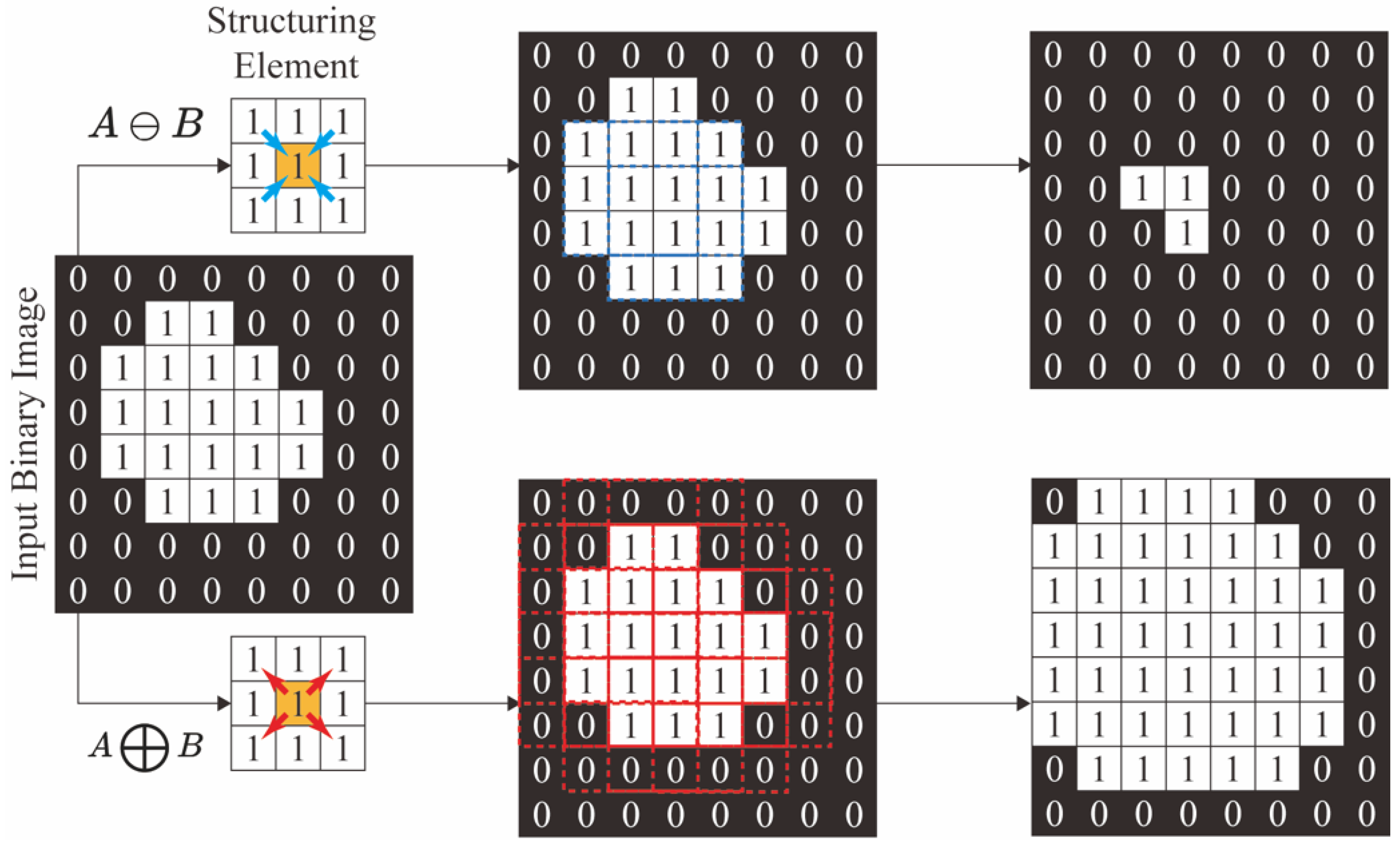
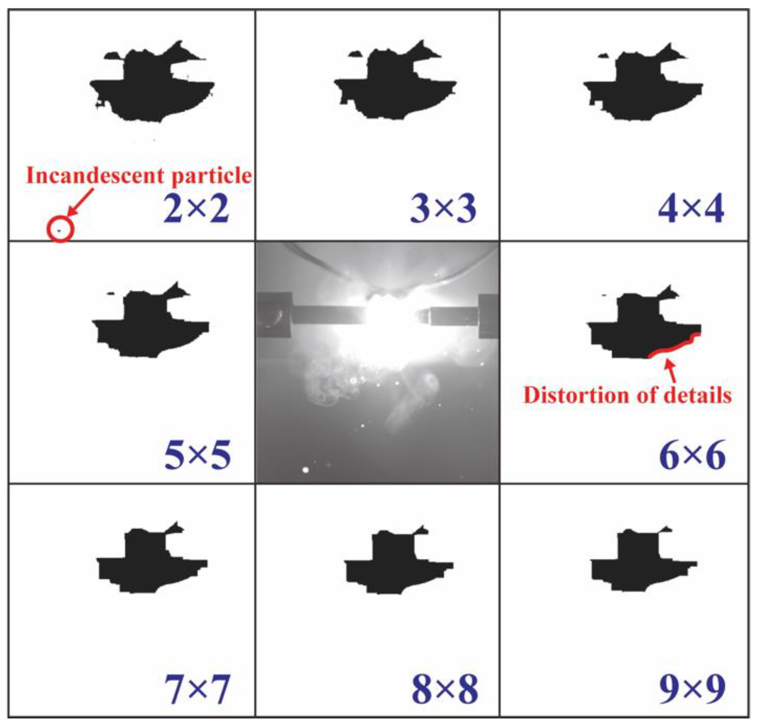
2-3 The principal part of the inverted binary image is extracted by the mathematical morphology operation with the structuring elements in different sizes.
Step 3: Flame marking & statistic
3-1 Mark the flame area in the original photo;
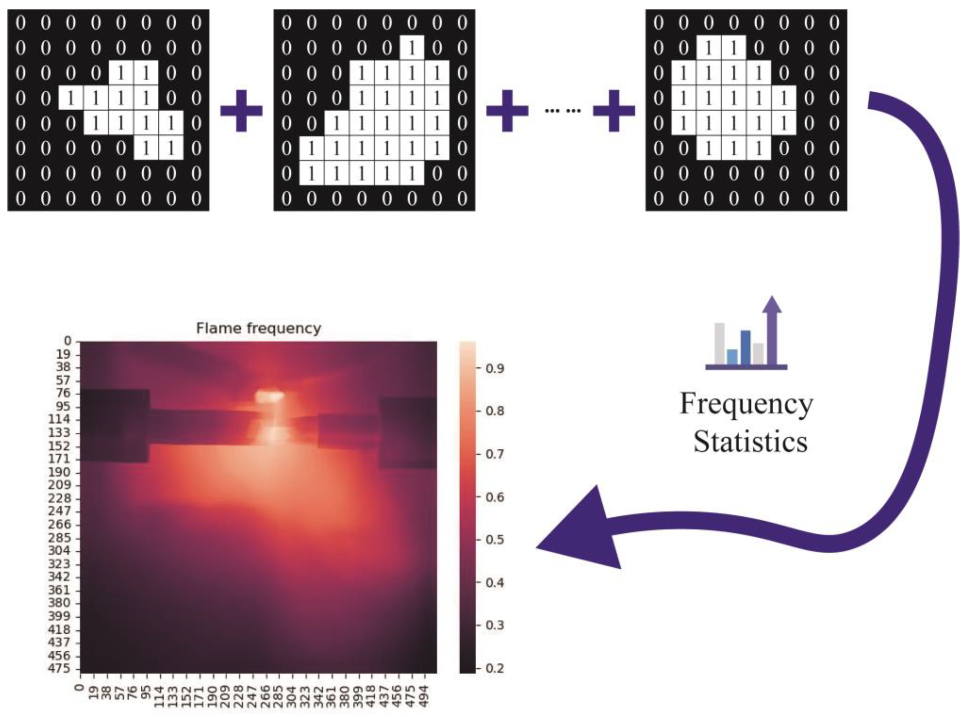
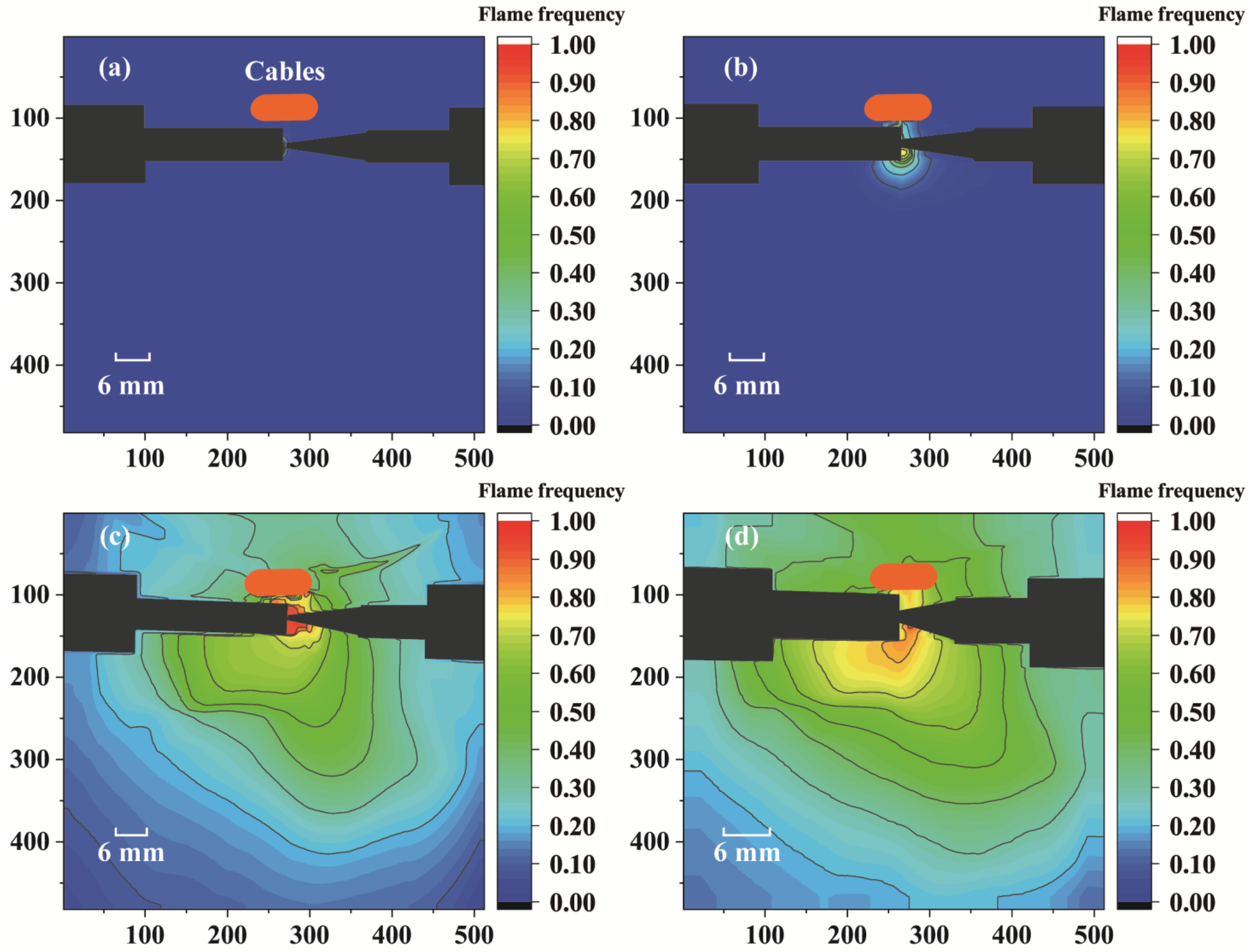
3-2 Overlay the images at all times, where the pixel value of the flame area is set to 1, and the pixel value of the non-flame area is set to 0, and count the frequency of the flame at each position in the camera field of view;
3-3 Calculate the actual area of the flame according to the distance ratio between the photo and the actual object.
The proposed algorithm was implemented by Python and operated on a desktop computer with Inter(R) Core (TM) i9-12900K @3.20GHz CPU, RAM 64 GB.

2.3. Image-Based Flame Data Extraction

After removing the reflections from the top wall of the stainless-steel experimental chamber, the greyscale photo was converted into the inverted binary image. Then, the mathematical morphology operation [31] was employed to extract the flame part of the photo.
A wide range of operators is available to process the inverted binary image due to the extensive development of mathematical morphology and set theory. Edge detection, noise removal, image enhancement, and image segmentation can be achieved using operators [32,33].
Erosion and Dilation operations were included in MMO of the binary image, where the input binary image was denoted as A , and the structuring element was denoted as B . The structuring element consisted of a pattern, including an origin and some surrounding discrete points. The erosion and dilation operations were conducted by translating the structuring element to each input inverted binary image pixel and examining their intersections [32,33].
The examples of the erosion and dilation operation are illustrated in Figure 3. The erosion operation was utilized to filter the scattered noise and the non-flame part of an image, and reduce the size of the object, expressed as Equation (1). On the other hand, the dilation operation was employed to filter the noise inside flame part of an image, and increased the size of object, expressed as Equation (2). The directional dilation was realized by using non-symmetrical structuring elements.
A B = b B A b
A B = b B A b
where denotes erosion operation, denotes dilation operation, and b denotes the pixels of B .
Concretely, the erosion operation was employed to filter the scattered noise and the extra part of the image, which diminished the size of the object, as presented in Equation (1). The dilation operation was utilized to filter the inner noise of the image and was made directional by using less symmetrical structuring elements, which increased the size of the object, as presented in Equation (2).
The structural element is the key of both the erosion and dilation operations. Equation (1) and Equation (2) established the mathematical division of the structural element, where the B of the above equations is the proposed structural element. Figure 3 further illustrate the operation mechanism of the structural element in a figural way. The above equations and figure can help establish and deliver the operation principle of the structural element.
Other mathematical morphology operations were generated by combining the erosion and the dilation operation. For example, ( A B ) B is defined as the opening operation, and ( A B ) B is defined as the closing operation. The opening operation is less destructive than the erosion operation. Therefore, the opening operation was used to identify the flame part in the high-speed photos.

2.4. Flame Marking & Statistic

The pixel value of the flame area was marked as 1, and the pixel value of the non-flame area was marked as 0. To obtain the flame distribution frequency in the photo, we superimposed the pixel values of each position of the matrix formed by the image pixel points at each moment. Then we divided them by the total number of pictures, as shown in Figure 4.

3. Results and Discussions

3.1. Performance of the Proposed Method

A photo taken under the 5.5k W system load was used as an example to implement the proposed method, where the structuring element varies from 2 × 2 to 9 × 9. Figure 5 presents the performance of the flame extracting and noise reduction algorithm. The flame can be effectively extracted, and the noise can be effectively cleaned. When the size of the structuring element is 2 × 2, the particle is wrongly recognized as flame due to some sizeable incandescent particles being the same bright as flame. As the size of the structuring element increases to 3 × 3, the prementioned incandescent particle can be effectively cleaned. However, it does not mean the larger structuring element can guarantee better recognition performance. As shown in the 6 × 6 structuring element in Figure 5, due to the excessive cleaning of the algorithm, the outer contour of the flame in the photo has a jagged distortion. Therefore, it is necessary to select the appropriate structuring element size through pre-testing. The selected structuring element size and filter gray value for each test set are listed in Table 1.

3.2. The Time Evolution Law of the Size of the Flame under Different System Loads

The mean flame area time under different system loads was calculated and is presented in Figure 6. There is an extremely significant increase in flame area between 7.7 kW and 8.8 kW system load, which means that when the system load is in this range, the cable insulation is ignited, and spontaneous combustion occurs. The mean flame area is smaller than 140 mm2 when the system load is lower than 7.7 kW. However, the mean flame area reaches about 1700 mm2 when the system load is 8.8 kW. The mean flame area fluctuates from 1500 to 2500 mm2 as the system load varies between 8.8 and 12.1 kW. It should be noted that for a 2000 mm2 circular flame, its radius can reach up to 25.23 mm, which is six times the radius of the cable sample. This phenomenon demonstrates the possibility of ignition of surrounding combustibles.
As shown in Figure 6, in the range of 2.2 to 7.7 kW system load, mean flame area and system load show an exponential relationship, and their relationship is obtained by fitting as S f l a m e = 5.57 P l o a d 6.11 , where S f l a m e is the mean flame area in mm2 unit, P l o a d is the system load in kW unit. However, the mean flame area does not comfort to this correlation when the system load is above 8.8 kW.

3.3. The Impact of the System Load on Flame Frequency Spatial Distribution

The frequency distribution of the flame in space under various system loads is illustrated in Figure 7. The flame grows in size as the system load increases, consistent with the result in the last section. In addition, the flame appears more frequently in specific locations. Therefore, it is foreseeable that when a series arc occurs, and the cable insulation is ignited, the greater the system load, the larger the size of the flame, the higher the frequency of flame occurrence, the stronger the ignition ability is, and the higher the fire hazard is.
In addition, the flame was found to be leaning towards the side of the copper electrodes, especially under a larger system load (see Figure 7c,d). The possible reason for this phenomenon can be attributed to the shape of the electrodes, where the carbon electrode is flat, while the copper electrode is sharp. Although this electrode configuration parameter is consistent with the ANSI/UL 1699 standard, attention should be paid to the influence of the experimental setup on the experimental results in future relevant research [6].

4. Conclusions

A series of experiments were conducted on a newly developed experimental platform to study the flame behavior during cable insulation material ignited by a fault arc. A flame extracting and noise reduction algorithm was proposed to process the enormous number of photos shot by a high-speed camera. The main conclusions are summarized as follows:
  • The size of the structuring element plays an essential role in filtering flame region in photos. A too-small structuring element may result in the wrong recognition of large incandescent particles in the flame, while too large a structuring element will give the outer contour of the flame in the photo a jagged distortion;
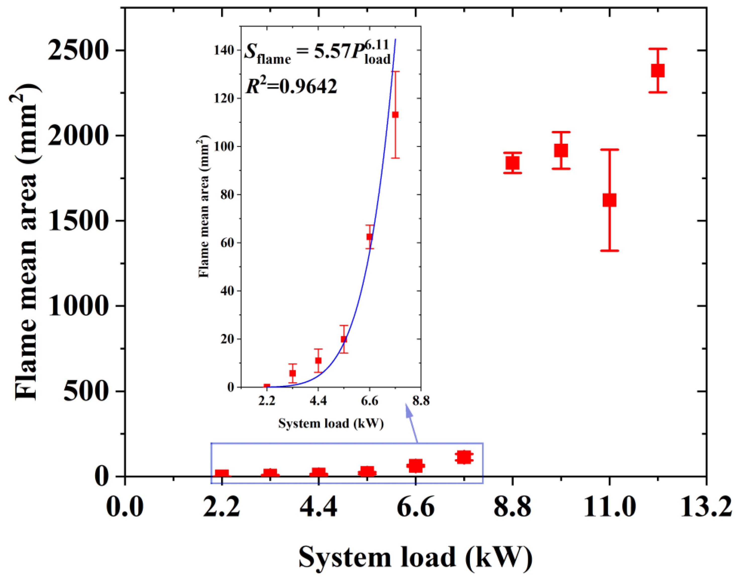
  • The flame mean area increased as the system load grew. An extremely significant increase in flame area was found between 7.7 kW and 8.8 kW of the system load. The flame mean area and the system load showed an exponential relationship in the 2.2 to 7.7 kW system load. When the system load was above 8.8 kW, the flame radius was able to reach six times the cable sample’s radius, exhibiting a significant ignition hazard to surrounding combustibles;
  • The flame behavior during cable insulation material ignited by a fault arc showed a dependence on system load. The flame size became more prominent and appeared more frequently in specific locations when the system load increased.

Author Contributions

Conceptualization, Y.W.; methodology, Y.W.; software, Y.W.; validation, J.L.; formal analysis, Y.W.; investigation, Y.W., C.L. and H.L.; resources, S.L.; data curation, Y.W.; writing—original draft preparation, Y.W.; writing—review and editing, J.L., S.L. and K.M.L.; visualization, Y.W.; supervision, S.L. and K.M.L.; project administration, S.L. and K.M.L.; funding acquisition, S.L. and K.M.L. All authors have read and agreed to the published version of the manuscript.

Funding

This research was funded by Fundamental Research Funds for the Central Universities, grant number WK2320000050 and the Research Grants Council of the Hong Kong Special Administrative Region, China (Project No. 9043135, CityU 11202721).

Institutional Review Board Statement

Not applicable.

Informed Consent Statement

Not applicable.

Data Availability Statement

The data presented in this study are available on request from the corresponding author. The data are not publicly available due to privacy issues.

Conflicts of Interest

The authors declare no conflict of interest.

References

  1. Campbell, R.B. Home Electrical Fires; National Fire Protection Association: Park Quincy, MA, USA, 2019. [Google Scholar]
  2. Babrauskas, V. Research on electrical fires: The state of the art. Fire Safety Science 2008, 9, 3–18. [Google Scholar] [CrossRef] [Green Version]
  3. Moon, W.-S.; Kim, J.-C.; Jo, A.; Bang, S.-B.; Koh, W.-S. Ignition Characteristics of Residential Series Arc Faults in 220-V HIV Wires. IEEE Trans. Ind. Appl. 2015, 51, 2054–2059. [Google Scholar] [CrossRef]
  4. Gregory, G.D.; Scott, G. The arc-fault circuit interrupter, an emerging product. In Proceedings of the 1998 IEEE Industrial and Commercial Power Systems Technical Conference, Edmonton, AB, Canada, 3–8 May 1998. [Google Scholar]
  5. Xiong, L.; Xiong, L.; Zeng, Z.; Yang, J.; Zhong, Y.; Guo, K. Mathematical Model and Characteristics of Low Current DC Fault Arc. Diangong Jishu Xuebao/Trans. China Electrotech. Soc. 2019, 34, 2820–2829. [Google Scholar]
  6. Babrauskas, V. Minimum Values of Voltage, Current, or Power for the Ignition of Fire. Fire 2022, 5, 201. [Google Scholar] [CrossRef]
  7. Babrauskas, V. Electrical Fires. In SFPE Handbook of Fire Protection Engineering; Hurley, M., Gottuk, D., Hall, J.R., Jr., Harada, K., Kuligowski, E., Puchovsky, M., Torero, J., Watts, J.M., Jr., Wieczorek, C., Eds.; Springer: New York, NY, USA, 2016; pp. 662–704. [Google Scholar]
  8. Babrauskas, V. Ignition of Wood: A Review of the State of the Art. J. Fire Prot. Eng. 2002, 12, 163–189. [Google Scholar] [CrossRef] [Green Version]
  9. Sanderson, J. Carbon tracking: Poor insulation combined with contaminants is potential fire cause. Fire Find. 2000, 8, 1–3. [Google Scholar]
  10. Blackburn, T.; Pau, L. Characteristics of a simulated high impedance fault. In Proceedings of the Electric Energy Conference 1985: Modern Trends in the Generation, Transmission, Distribution and Utilisation of Electrical Energy, Springfield, IL, USA, 28–30 April 1985. [Google Scholar]
  11. Kinbara, T.; Sue, S. On the Outbreak of Fire due to Leakage of Electricity from Neon-Transformer through Planking. Bull. Jpn. Assoc. Fire Sci. Eng. 1953, 2, 39–41. [Google Scholar]
  12. Kinbara, T.; Takizawa, K. Ignition of a Salt-soaked Wooden Board by an Electric Current through it: Part 1. Bull. Jpn. Assoc. Fire Sci. Eng. 1961, 11, 26–31. [Google Scholar]
  13. Yin, B.; Sun, W.; Zhang, X.; Liew, K. Deciphering structural biological materials: Viewing from the mechanics perspective and their prospects. Compos. Part B-Eng. 2022, 245, 19. [Google Scholar] [CrossRef]
  14. Wang, Y.; Kang, N.; Lin, J.; Lu, S.; Liew, K.M. Cross-heating-rate prediction of thermogravimetry of PVC and XLPE cable insulation material: A novel artificial neural network framework. J. Therm. Anal. Calorim. 2022, 12, 14467–14478. [Google Scholar] [CrossRef]
  15. Fernandez–Pello, A.C.; Hasegawa, H.K.; Staggs, K.; Lipska-Quinn, A.E.; Alvares, N.J. A study of the fire performance of electrical cables. In Fire Safety Science—Proceedings of the Third International Symposium; Routledge: Abingdon, UK, 2006. [Google Scholar]
  16. Hoffmann, J.; Hoffmann, D.; Kroll, E.; Wallace, J.; Kroll, M. Electrical Power Cord Damage from Radiant Heat and Fire Exposure. Fire Technol. 2001, 37, 129–141. [Google Scholar] [CrossRef]
  17. Novak, C.J.; Stoliarov, S.I.; Keller, M.R.; Quintiere, J.G. An analysis of heat flux induced arc formation in a residential electrical cable. Fire Saf. J. 2013, 55, 61–68. [Google Scholar] [CrossRef]
  18. Iwashita, T.; Keller, M.R.; Hagimoto, Y.; Sugawa, O. Leakage currents precede short circuits in PVC-insulated cable when exposed to external radiant heat. Fire Mater. 2017, 41, 339–348. [Google Scholar] [CrossRef]
  19. Iwashita, T.; Hagimoto, Y.; Sugawa, O. Characterization of arc beads on energized conductors exposed to radiant heat. Fire Mater. 2017, 41, 1072–1078. [Google Scholar] [CrossRef]
  20. Iwashita, T.; Hagimoto, Y.; Sugawa, O. Survey of fire testing of electrical cables. Fire Mater. 1992, 16, 107–118. [Google Scholar]
  21. Fisher, R.P.; Stoliarov, S.; Keller, M. A criterion for thermally-induced failure of electrical cable. Fire Saf. J. 2015, 72, 33–39. [Google Scholar] [CrossRef]
  22. Shea, J.J. Comparing 240 Vrms to 120 Vrms Series Arcing Faults in Residential Wire; IEEE: Piscataway, NJ, USA, 2008. [Google Scholar]
  23. Shea, J.J. Identifying causes for certain types of electrically initiated fires in residential circuits. Fire Mater. 2011, 35, 19–42. [Google Scholar] [CrossRef]
  24. Takenaka, K.; Ishikawa, Y.; Mizuno, Y.; Lin, W. Arc Discharge–Induced Ignition of Combustibles Placed on a Damaged AC Power Supply Cord. Energies 2020, 13, 681. [Google Scholar] [CrossRef] [Green Version]
  25. Li, Y.; Sun, Y.; Gao, Y.; Sun, J.; Lyu, H.-F.; Yu, T.; Yang, S.; Wang, Y. Analysis of overload induced arc formation and beads characteristics in a residential electrical cable. Fire Saf. J. 2022, 131, 8. [Google Scholar] [CrossRef]
  26. U.L. Inc. UL Standard for Arc-Fault Circuit-Interrupters, 3rd ed.; Underwriters Laboratories Inc.: New York, NY, USA, 2017. [Google Scholar]
  27. Long, H.; Sang, L.; Wu, Z.; Gu, W. Image-Based Abnormal Data Detection and Cleaning Algorithm via Wind Power Curve. IEEE Trans. Sustain. Energy 2020, 11, 938–946. [Google Scholar] [CrossRef]
  28. Wang, J.; Wang, J.; Shao, J.; Li, J. Image Recognition of Icing Thickness on Power Transmission Lines Based on a Least Squares Hough Transform. Energies 2017, 10, 415. [Google Scholar] [CrossRef] [Green Version]
  29. Liu, Y.; Urban, J.L.; Xu, C.; Fernandez-Pello, C. Temperature and Motion Tracking of Metal Spark Sprays. Fire Technol. 2019, 55, 2143–2169. [Google Scholar] [CrossRef]
  30. Yan, W.G.; Wang, C.; Guo, J. One Extended OTSU flame Image recognition Method Using RGBL and Stripe segmentation. In Proceedings of the 2nd International Conference on Frontiers of Manufacturing and Design Science (ICFMD 2011), Taichung, Taiwan, 11–13 December 2011; Trans Tech Publications Ltd.: Taipei, Taiwan, 2011. [Google Scholar]
  31. Haralick, R.M.; Sternberg, S.; Zhuang, X. IMAGE-ANALYSIS USING MATHEMATICAL MORPHOLOGY. IEEE Trans. Pattern Anal. Mach. Intell. 1987, 9, 532–550. [Google Scholar] [CrossRef]
  32. Zhang, A.Q.; Ji, T.Y.; Li, M.S.; Wu, Q.H.; Zhang, L.L. An Identification Method Based on Mathematical Morphology for Sympathetic Inrush. IEEE Trans. Power Deliv. 2018, 33, 12–21. [Google Scholar] [CrossRef]
  33. Deng, C.X.; Wang, G.B.; Yang, X.R. Image Edge Detection Algorithm Based on Improved Canny Operator. In Proceedings of the International Conference on Wavelet Analysis and Pattern Recognition (ICWAPR), Tianjin, China, 14–17 July 2013; IEEE: Piscataway, NJ, USA, 2013. [Google Scholar]
Figure 1. Experimental setup of arc generator and cable sample.
Fire 06 00045 g001
Figure 2. Image-based data cleaning algorithm process, “*.jpg” refers to any photo under certain experimental condition.
Fire 06 00045 g002
Figure 3. Examples of the erosion and dilation operation by using 3 × 3 structuring elements.
Fire 06 00045 g003
Figure 4. Flame marking and statistic.
Fire 06 00045 g004
Figure 5. The flame extraction and noise reduction performance of the proposed algorithm with various structuring elements.
Fire 06 00045 g005
Figure 6. The mean flame area time under different system loads.
Fire 06 00045 g006
Figure 7. The frequency distribution of the flame under different system loads: (a) 3.3 kW, (b) 6.6 kW, (c) 9.9 kW, (d) 12.1 kW.
Fire 06 00045 g007
Table 1. Parameters for the selected algorithm execution after testing.
No.System LoadStructuring Element XStructuring Element YFilter Gray Value
12.279230
22.235230
33.335230
43.335230
53.335230
64.455230
74.433230
84.433230
95.533230
105.533230
115.553230
126.653230
136.653230
146.653230
157.733230
167.733230
177.733230
188.833230
198.857230
208.833230
219.933230
229.953230
239.933230
241133250
251133250
261133250
2712.175250
2812.175252
2912.179253
Disclaimer/Publisher’s Note: The statements, opinions and data contained in all publications are solely those of the individual author(s) and contributor(s) and not of MDPI and/or the editor(s). MDPI and/or the editor(s) disclaim responsibility for any injury to people or property resulting from any ideas, methods, instructions or products referred to in the content.

