Abstract
This paper presents experimental research findings for those involved in the early phase of fire in office buildings. Class A model fires with a reaction area from 5 cm2 to 300 cm2 were chosen for investigation. To mock up a fire, the following combustible materials typical of offices were used: wood pieces, heat-insulated linoleum, paper and cardboard. The main characteristics of a model fire were recorded: temperature in the combustion zone, heat release, time of complete burnout and concentration of flue gas components. Typical trends and histograms of changes of these characteristics over time were presented; stages of ignition, flame combustion and smoldering were illustrated. The key characteristics of fire detector activation at different stages of model fire combustion were analyzed. Dead bands and operation conditions of a group of detectors (smoke, heat, optical, flame), their response time and errors were identified. It has been established that the most effective detectors are flame and smoke detectors. Specific operational aspects of detectors were established when recording the ignition of different types of model fires. The viability of combining at least two detectors to record fire behavior was established. Recommendations were made on using the obtained findings when optimizing the systems for detecting and recording the start of a compartment fire.
1. Introduction
The analysis of fire statistics in different types of buildings and facilities [1,2] reveals the limited capabilities of existing fire detection and extinguishing systems. Fire source detection is crucial for the fire safety of enclosed spaces [3,4,5]. In accordance with GOST 12.1.044-89 (ISO 4589-84), a set of indicators was adopted [6] to classify the fire and explosion safety of substances and materials of different states of matter. In [6], 20 indicators of fire and explosion safety are listed, characterizing the conditions at the beginning of the flame combustion of liquids and gases, as well as solid substances. On residential and business premises, solid combustible materials prevail. These include household items, home decoration and materials used for interior finishing. For solid combustible substances and materials, 9 key indicators of fire and explosion safety were accepted [6]. In warehouses and industrial premises, not only solid combustible substances are stored but also combustible liquids and gases. Flammable and highly explosive dust is also generated there. It is accumulated as a result of industrial processes at enterprises that can be ranked class A in terms of fire hazards. The ignition of combustible liquids is characterized [6] by 14 key indicators. The gases have 10 fire performance indicators. Combustible dust ignition is classified by 11 main criteria. The autoignition temperature and combustibility when interacting with water, oxygen and other substances are basic parameters for all the groups of substances and materials irrespective of their state of matter. All the combustible substances are characterized by a group of indicators: flammability limits, minimum ignition energy, minimum explosion-hazardous content of oxygen, and minimum concentration of phlegmatized explosive (the lowest phlegmatizer concentration in the mixture with a combustible substance and oxidizer at which the mixture becomes incapable of flame spread at any combustible substance/oxidizer ratio). For liquids and gases, the normal burning rate and diffusion flame limits of gas mixtures in the air are accepted indicators. At the same time, the smoldering temperature and thermal autoignition conditions are basic for solid substances (including dust). Combustible substances in a liquid state can be classified by flash temperature, temperature limits of flame spread and burnout rate. For solid combustible substances, the following characteristics of fire and explosion safety are singled out: oxygen index, smoke generation coefficient, flame spread index and indicator of decomposition product toxicity. Table 1 presents the indicated characteristics of the substances and materials.

Table 1.
Indicators of fire and explosion safety of substances and materials [6].
Most firefighting systems employ point-type fire detectors (heat, smoke, optical and combined) that react to one of fire signs (smoke blanketing, increase in the thermal or infrared radiation, etc.) However, the accuracy and response time of spot-type detectors do not always meet the requirements of compartment fire detection. Thus, for instance, smoke and heat detectors respond only at the growth stage accompanied by heavy smoke. Consequently, the fire-extinguishing system is activated late, leading to significant financial losses. Intelligent fire detection systems identify fires in buildings and closed spaces at incipient stages. Such systems rely on machine vision [7,8,9,10]. Electro-optical devices for the visual control and automatic analysis of images detect the fire source faster than point-type detectors. IP cameras also determine the size and direction of the flame front movement, which is impossible using data from local detectors. However, the limitation of optical recording equipment is its fixed field of view. Thus, it is necessary to install several cameras to simultaneously monitor the entire perimeter of the object under observation. This leads to an increase in computing power and, consequently, the costs associated with creating such systems. Moreover, intelligent fire detection systems respond to visible signs of a fire, such as flame combustion and rapid heat release. In isolated systems, e.g., ships and submarines, late detection of the fire source and transition from the smoldering decomposition mode to flame combustion can lead to severe consequences and people’s deaths [11].
The above-mentioned limitations of fire detection systems show that a group of factors indicating a fire at different stages (thermal decomposition, flame combustion or smoldering smoke) should be recorded. Such indicators might be flame luminance, heat release, combustion temperature, sizes and rate of the fire front spread, charring rate, etc. The heat release rate during the combustion of material makes it possible to estimate the rate of flame spread, fire size and temperature in an enclosed space. The collected information assists in calculating the required time and direction for evacuation. Thus, it appears possible to predict the necessary and sufficient consumption of fire-extinguishing agents and the time of fire suppression [12].
A number of studies, in particular refs. [13,14,15,16,17], analyze the measurement of fire characteristics (such as temperature fields, heat release, spread rate, etc.) during a fire. The obtained findings were used to assess the fire hazards of buildings when developing their fire protection. Thus, Zhang et al. [13] evaluated fire hazards in a building by flame height and heat release from the fire. A formula was derived to calculate a temperature increase in an enclosed space. The risk parameters of fires in poorly ventilated rooms were evaluated. Mitrenga et al. [17] measured the ignition temperatures of upholstered furniture and its combustion surface temperatures when exposed to an ignition flame. A delay in textile material heating was analyzed. The research findings [13,14,15,16,17] can be used to evaluate fire hazard risk and to set the activation parameters of fire detection systems.
The results of experimental research into the specific aspects of combustion of an indoor wooden frame construction are presented in [18]. In particular, the temperature in the combustion zone, weight loss of burning materials, temperature profiles outside the openings-facade wall and the size of emerging flame were estimated. It was experimentally established that the damage to the internal linings of walls as a result of fire in a building sharply increases the temperature (up to 900 °C) and leads to the second heat release rate peak (15.25–19.49 MW). This indicates that the readings of detectors, recording the rates of heat release during a fire, may help identify the destruction of a wall structure and the high probability of flame spreading to neighboring rooms.
Such characteristics of wood (oak, larch, cedar) combustion as heat release rate, charring rate and toxic gas yield (CO and CO2) were studied in [19]. It was shown that wood combustion behavior at a low heat flux (q ≈ 20 kW/m2) differs significantly from that at q more than 35 kW/m2. The wood species differ in the ignition time and the rates of heat release, charring and flame spread. The findings obtained are a guide to the design of fire-resistant wooden structures with the lowest concentrations of toxic substance emissions and confirm the need to set the measurement ranges of firefighting system detectors, depending on fire behavior.
During fires in buildings and enclosed spaces, self-sustaining combustion is coupled with combustion caused by another flame source (neighboring burning objects). Diab et al. [20] present the results of comparing the combustion behavior of wooden constructions under such conditions. In both cases, the combustion and flame spread rates were found to be almost identical. However, the temperature profiles along the centerline above the fire were significantly different for the self-sustaining burning of the material when exposed to the second flame source. Changing the crib fire geometry (increasing the number of layers of material) was found to affect the fire behavior (heat release rates and flame height). The ranges of the fire source characteristics measured by detectors can be set depending on the dimensions of the monitored object (this approach is especially relevant for materials in warehouse racks since they have regulated dimensions).
Insufficient ventilation in a building can cause hot air to accumulate beneath the ceiling [21]. The source of fire at its early stages is usually local and low temperatures. Therefore, thermal radiation detectors should be supplemented with those that can identify fire signs signaling an incipient fire stage. Such signs include combustion products and other gases (CO, CO2) in the thermal decomposition products of materials and substances. Thus, detectors capable of detecting relatively low concentrations of such gases over a wide range are becoming more widespread. Although studies in this field have mainly focused on detecting the toxic hazard of compartment fires, the possibility of using detectors recording gaseous pyrolysis products to detect combustion at an early fire stage (thermal degradation of material) has been substantiated [22,23]. For instance, Qiu et al. [22] describe the results of developing an early fire detection system based on a laser spectroscopic carbon monoxide detector. The potential for using such detectors in fire detection and suppression systems was justified.
The specific aspects of changes in fire behavior (concentrations of toxic combustion products and thermal decomposition of substances and materials) in an enclosed space at early fire stages were discussed in [23]. In particular, differences in the gas concentrations at the stages of fire containment and suppression (as a result of liquid supply) were established. A spray system activation was shown to lead to higher carbon dioxide concentrations. This trend [23] is attributed to inefficient fire suppression caused by low water discharge density and late activation of the spray system. An interesting finding was obtained in [24], where the minimum discharge density of aqueous film-forming foam (AFFF), necessary to suppress a fire, depending on its size, was established.
The research [25] deals with gaseous emissions, heat release rates and mass loss during the combustion of polyether polyurethane foam at irradiance levels in the range of 10–50 kW/m2. The main gases recorded were CO2, CO, H2O and NO. The analysis of the gaseous emissions released from combustion revealed two stages of material decomposition. The effective heat of combustion and the ratio of the heat release rate to the CO2 yield, recorded during a fire make it possible to draw some conclusions to define fire stages and detect the thermal decomposition of material in a timely manner.
Bluvshtein et al. [26] provided evidence for using organic particle emissions as early signs of fire start (smoldering) at temperatures below 150 °C. The object of the research was wood. The heating of wood pellets to 85–100 °C was shown to release low-volatility organic compounds, followed by the formation of sub-micron organic aerosols. It was established that with a lack of oxygen, the concentrations of CO and CO2 are not always reliable indicators of heating and drying stages preceding the thermal decomposition of material and its smoldering combustion, whereas high concentrations of sub-micron particles may be used as such indicators. High concentrations of sub-micron particles were shown to be produced at temperatures that are 20–30 °C lower than is required for a significant change in CO and CO2 concentrations.
The findings from [12,27,28] are of special interest in the field of fire behavior and the application of results in fire suppression and detection systems. Noaki et al. [27] determined the intensity of heat release from wooden cribs when liquid was applied for fire suppression. The reduction in the maximum heat release rate was found to be proportional to the water flow rate. The variable experimental parameters were the number of wooden layers, water discharge density and time of spray system activation. As pointed out [27], fire suppression using sprinkler systems is only effective with sufficient water discharge density and timely spray system activation based on fire behavior. The trends in heat release rates after water application are also presented in [27]. The following outcomes were shown to be possible: (1) material is extinguished immediately after sprinkler activation; (2) after spray system activation, combustible materials and substances continue burning, though the heat release rate significantly decreases; (3) after liquid is injected, the rate of heat release keeps rising; and (4) no liquid was applied. Since the heat release rate starts rapidly changing after finishing stable combustion, it is advisable to use data from other detectors to record fire behavior. The experimental research findings for the characteristics of fire suppression systems with continuous and cycling water supply are presented in [12]. Zhou et al. [12] analyzed the characteristics of smoke temperature changes, total and radiative heat fluxes, time of fire suppression, concentrations of carbon monoxide and oxygen at the stages of self-sustaining combustion of material and when water mist is applied. A conclusion was made that a fire is extinguished faster when the cyclic spraying mode with a minimum turn-off time is used. It was established that, using this liquid supply scheme, the changes in the smoke temperature and heat flux follow a cyclical pattern. The maximum concentrations of CO and O2 are lower when using cyclic water discharge than when using a continuous water supply. Such systems are preferable when evacuating people from combustion zones. A decision about turning off a fire suppression system is made following the analysis of the fire behavior variation trend. Gorska et al. [28] determined the rates of heat flow caused by the combustion of wood during compartment fires. Data were obtained about the flue gas temperatures, heat release during wood combustion and contribution of these characteristics to the evaluation of the overall state of the monitored object during a fire. The gas flow velocity was shown to increase with an increase in wood mass. An important trend was established; a fire moves on to a new mode when gases inside an enclosed space do not mix or react, whereas the rates of combustion and heat release increase.
The research findings presented above can be applied to describe the stages of fire development in buildings and premises, as well as to design fire safety systems [29,30,31]. To perform a comprehensive analysis of the combustion of materials and optimize systems of recording them to develop a strategy for extinguishing them at different combustion stages, it is necessary to experimentally determine the trends of fire behavior (temperatures and heat fluxes in the combustion front, flue gas concentrations) and substantiate the choice of a group of detectors for detecting the incipient fire stages.
The purpose of this study was to determine fire behavior at early combustion stages and to determine the influence of compartment fire behavior at ignition and combustion development stages on the operation of fire detectors.
2. Materials and Properties
The most fire-hazardous compartments are those with combustible substances and materials that can catch fire and spread the flame, leading to class A fires. Such objects include residential buildings, business premises and warehouses. According to [19,20,26,27,28], wood is one of the most common and fire-hazardous materials. Wood is widely used in construction, finishing and furniture manufacturing. A great amount of wood is found as pallets for goods storage in different types of warehouses. In particular, the warehouses of furniture factories and wood working enterprises have unprocessed timber, chips and sawdust, posing a serious fire and explosion hazard. Offices and warehouses often have flammable floorings and may contain certain amounts of paper documents. Therefore, class A fires with an area from 5 cm2 to 300 cm2 were chosen as seats for fire in this study. For mock-up of fires, the following combustible materials typical for office premises were used: wood pieces, heat-insulated linoleum, paper and cardboard. Wood and its derivatives (cardboard and paper) are highly flammable in the air, and fire quickly sweeps over their surface (in terms of the flame spread indicator, e.g., pine is a moderately flammable material, the critical areal heat flow is 5–8 kW/m2 (RP3 in accordance with GOST R 51032–97 [32])). When pine is heated, complex carbonization reactions proceed, and the dynamics of dangerous fire consequences, such as smoke, heat and flue gas release, have specific aspects. The stages of wood combustion lie within certain temperature ranges, which makes it possible to experimentally describe them in detail. In particular, the ignition temperature of pine is 255 °C, and the autoignition temperature is 350–400 °C [33]. The combustion temperature can reach 900 °C. The materials used for the interior finishing of business premises, residential spaces and warehouses include linoleum, paper and cardboard. The fuel moisture content [34,35] was determined by the thermal drying method and was: wood—10%; linoleum—3%; paper, cardboard—7%. Air humidity inside the SC was about 28%.
To conduct the experimental research, a definite mass of materials, determined experimentally, was chosen for burning. It ranged from minimum to maximum. The maximum mass corresponds to the condition when all the fire detectors are activated or when the detectors are activated within the shortest possible time. Table 2 illustrates the limit masses of the typical combustible materials under study.

Table 2.
Characteristics of combustible materials used in the experiments.
To extinguish fires in the above mentioned spaces, sprinkler and deluge systems are mainly used with water as a firefighting agent [36]. The wide application of water to extinguish a compartment fire is conditioned by its high cooling and diluting effects (due to its high heat capacity and vaporization heat). When sprayed water is applied to a fire, it almost instantly suppresses the flame, displaces oxygen and settles smoke. Furthermore, water is considered the safest fire-extinguishing agent for human health, in contrast to specialized compositions (foam, powders, suspensions), which may cause irreparable damage to high-cost equipment and structures of buildings in general. This is why water was chosen as a fire-extinguishing agent in the conducted experiments.
3. Experimental Setup and Technique
Figure 1 illustrates the setup. The experimental complex consisted of an isolated setup chamber (SC), a distribution board, recording devices and systems (Thermocouples, Thermal imager, Gas detection system (GDS), Flame detectors (FD), Heat detectors (HD), Smoke detectors (SD), and a PC to collect and process information. The SC for the model fire was 1.5 × 1 × 1.25 m, with sides made of magnesium oxide boards attached to an aluminum structural frame. The observation window was made of 4-mm-thick fire-resistant glass with dimensions 0.7 × 0.8 m. There was no thermal insulation of the SC. The SC was insulated solely for the purpose of restricting the inflow of air from the outside, as well as the release of combustion products into the external environment. There was supply ventilation (SV) on the lower sidewall of the setup. On the opposite side, in the upper part of the setup, there was exhaust ventilation (EV) (Figure 1c). In the SC (Figure 1b,c), fire point-type detectors (fire detectors and thermocouples) were used to record the fire behavior and the moment of ignition, as well as a gas analysis system (GDS sensors were mounted at the same level as FD).
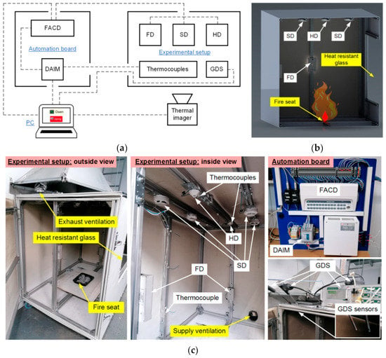
Figure 1.
Architecture of experimental complex (a), setup layout (b), appearance of the main elements (c): FACD—Fire alarm control device, DAIM—Digital and analog input module, FD—Flame detector, SD—Smoke detector, HD—Heat detector, GDS—Gas detection system.
To measure the model fire temperatures, the experimental setup was additionally equipped with a Testo-885 thermal imager (spectral range 7.5–14 µm; temperature range −30–1200 °C; emissivity 0.01–1; frame resolution 640 × 480 pix). The data from the imager were transferred directly to the PC. The signals from the point-type detectors (FD, HD, SD) were sent to the distribution board (Figure 1a). The distribution board was equipped with a set of electric devices to display data from fire detectors, collect information from the detectors and signals from thermocouples, and transmit them to the PC for subsequent recording and analysis. Dashed lines in Figure 1a show the electrical wire connections of a group of flame (FD), smoke (SD) and heat (HD) detectors to a Signal-20M fire alarm control device (FACD) and the connections of the devices to the PC. The FACD transmits a signal to the discrete and analog input module (DAIM) through discrete outputs and a group of contact relays when one or several connected detectors are activated. The DAIM collects and transfers data for subsequent recording and display on the PC using dedicated Owen Process Manager software. The thermocouples were directly connected to the DAIM. To program the fire alarm circuit configuration and reset the FACD power and fire detectors, the device was connected to a PC with UProg software.
3.1. Fire Detectors
All point-type detectors (FD, HD, SD) were mounted on the setup frame. Optical flame detectors (Manufacturer “KB Pribor”, Yekaterinburg, Russia; field-of-view angle 120°; activation time 4.5 s) were fitted on one of the side walls of the setup (detector mounting height relative to the base of the model fire was varied in the experiments from 0.25 to 1 m). Smoke detectors (activation time usually no more than 5–9 s) and heat detectors (activation time 58–100 s with a rate of temperature rise 30 °C/min, temperature threshold 54–65 °C) were installed on the setup ceiling (at a distance of 1 m above the fire). Different locations of the detectors were considered to identify the effect of this factor on the fire detector performance characteristics. Four type K thermocouples (measurement range 0–1200 °C, systematic error ±2.5 °C, thermal response time 3 s) were placed in the area of potential combustion to record the temperature trends. Two thermocouples were located in the lower part of the free space of the setup body, and the other two were immediately placed under the heat detectors (Figure 1c).
Heat detectors (HD) (IP 101-1A-A1 type) are typical fire alarm system devices. They are installed in places where heat can be released during a fire and when other detectors might not be very effective. It is impractical to use them in facilities where there are frequent temperature fluctuations since that could give frequent false alarms. The heat detectors used in the experiments included a controller to which a sensitive element (heat detector) was connected. The data from the controller are transmitted through a circuit to the fire alarm control device (FACD). In the standby mode, the ambient temperature is measured discretely by the detector for a short time at intervals of 6–8 s. When the ambient temperature reaches a threshold value, the detector switches to the Fire mode (a dry contact detector is activated). In this mode, the current drawn through the fire alarm circuit increases, and the light-emitting diode (LED) indicator of the detector gets a solid red light on. The detector goes into standby mode when the fire alarm circuit voltage is turned off for at least 2 s.
The mechanism of the smoke detectors (SD) (IP 212-141 type) being used relies on the scattering of the light flow passing through the smoke particles. An infrared LED creates a light flow that is detected by the receiver. A change in the parameters of the light flow (decrease in its intensity) causes the microprocessor of the detector to send a Fire alarm signal through the circuit (the dry contact detector is activated), and the optical indicator has a solid light. Two kinds of smoke detectors were used in the experiments. The first type is detectors connected to the FACD directly through the fire alarm circuit (SD1, SD2); the second type is radio channel detectors connected to the FACD using a wireless interface (SD3, SD4) (Figure 1c).
The mechanism of optical flame detectors (FD) (Pulsar 1-01N type) is based on converting infrared (IR) radiation in the range of 0.8–1.1 µm, to which the sensitive element responds, into an electrical signal. Thus, the optical signal of the open flame in the infrared radiation range is sent to the primary transducer of the detector, which converts the photoelectric signal into electrical resistance. The secondary transducer converts resistance into voltage. The AC component of the signal is increased by the amplifier with an adjustable gain. Its adjustment determines the fire detection range. The signal components characteristic of the flickering flame were detected using a band filter. The flickering flame pulsations accumulate in the storage assembly. The signal from the storage assembly outlet goes to the shaping circuit. If the signal exceeds the preset level, the shaping circuit transmits a control signal to the key device. The key device is connected to the resistor circuit with a resistance of 1000 Ω. This increases the circuit current, and the light indicator on the detector front panel turns on (Fire mode). The detector returns to standby mode after the supply voltage is removed from the circuit for at least 2 s.
The fire alarm circuit parameter setting and the FACD control were maintained using UProg software. It allowed configuring the fire alarm circuits, namely, choosing the characteristics (resistance, current, activation threshold) and type of input (fire smoke, fire heat, programmable process inputs), as well as programming the relay output parameters (type of signal, event activating the system). Owen Process Manager software allows real-time recording and monitoring of the thermocouple readings and fire detector (FD, HD, SD) activation signals transmitted to the PC from the DAIM. The data recorded by the software can be exported and processed.
3.2. Gas Analysis
The gas concentrations in the SC were determined using a GDS system. It comprised industrial (Testo-340) and laboratory (Test-1) gas analyzers. The gas analyzer probes were placed in the area of a prospective fire (Figure 1c). During the combustion of the model fires, the gas concentration (CO, CO2, O2) dynamics were recorded. The data were saved on a PC and then processed and analyzed. The characteristics of the sensors in the GDS gas analyzers are presented in Table 3.

Table 3.
Characteristics of gas analyzers in the GDS.
The Test 1 gas analyzer includes seven electrochemical sensors (Table 3). There are also optical sensors for CO2 and CH4, as well as polarographic sensors for H2. The optical gas sensor utilizes the absorption of a certain (usually infrared) light wavelength by carbon dioxide (methane). The absorption coefficient was proportional to the gas concentration. The infrared detection method features high selectivity (the readings are not affected by the content of oxygen in the air) and accuracy. The H2 sensor is a universal electrochemical sensor with a liquid electrolyte inside. It transforms the partial pressure of hydrogen in gas mixtures into a normalized analog signal of direct voltage. There is also a water trap, a sample filtration system and pumps in the Test 1 gas analyzer. The water trap and the filter are necessary to dehumidify the flue gas and remove dust and soot particles (thus preventing condensate droplets and solid particles from damaging the sensor). The Test 1 gas analyzer was connected to the PC via RS-232. The Test software was used for real-time data display, storage and subsequent analysis.
The Testo-340 gas analyzer sensors (Table 3) are electrochemical. The CO2 concentration was based on O2 depletion. The operation of the sensors relies on chemical reactions developing in the electrochemical cell, which contains an electrolyte solution and electrodes (anode and cathode). When a certain gas enters the electrochemical cell, charged ions emerge in the solution. An electric current proportional to the concentration of the component analyzed in the gas mixture starts flowing between the electrodes. The electrical sensor processes the resulting electrical signal. The Testo 340 gas analyzer was connected to the PC via a standard USB interface. The EasyEmission software was used for real-time data display, storage and subsequent analysis.
The processing of the experimental data obtained using the GDS involved averaging the experimental results and determining the confidence intervals and errors. The average concentrations of the gas mixture components were calculated using the trapezoidal rule.
3.3. The Start Fire
The model fire was made up of a metal pallet placed in the lower central part (base) of the experimental setup (Figure 1b,c). A gas burner was applied uniformly over the surface area to start a fire. The flame application time ranged from 10 to 90 s, depending on the fire sizes that were conditioned by the mass of combustible materials. The lowest flame application time was for paper and the highest was for wood. The following fire (combustion) stages were singled out in the conducted experiments [37]: initial stage—smoldering of the material starts after the gas burner flame is applied, there is no flame combustion; sustained flame growth—unstable, short combustion (without the gas burner flame) that determines the transition of the initial stage of the fire to its developed stage; flame combustion—a combustible material burns out with an observable flame; smoldering—a combustible material burns out without an observable flame.
Experimental procedures. Each experiment included the following stages:
- A model fire with the necessary type and mass of materials was placed into the SC;
- UProg (FACD), Owen Process Manager (DAIM), and Test and EasyEmisson (GDS) software packages were run on the PC. The fire detector (FD, HD, SD) parameters were set, along with the characteristics of analog and discrete channels of DAIM; the gas analyzer settings (GDS) were chosen;
- The model fire combustion was initiated. The PC started recording the readings of thermocouples (TC), fire detectors (FD, HD, SD) and GDS sensors. The model fire visualization was also started using the thermal imager;
- The TC, FD, HD, SD and GDS readings were recorded until the model fire stopped smoldering (which was determined by the thermal imager readings);
- The experimental results were saved on the PC, where their primary processing was performed. During processing, the following major parameters were determined: model fire surface temperature (Tf); temperature (T) at different points of the SC; complete burnout time of the model fire (tf), fire detector activation time (tD); concentrations of CO, CO2 and O2 in the SC.
For each type and mass of combustible materials, a set of 5–8 experiments was conducted.
3.4. Measurement Errors
The systematic errors are due to fire detector (FD, HD, SD) activation delays, time of the FACD-DAIM-PC signal transmission, accuracy of temperature measurement by thermocouples at certain points of the experimental setup, as well as accuracy of the DAIM measurement channel, thermal imager and GDS.
The activation delay times of the fire detectors used in the experiments are specified in the data sheets and are no more than 4.5 s for FD; no more than 5 s for SD connected through the fire alarm circuit; and no more than 9 s for radio channel SD. For HD, the response time ranges from 580 to 820 s with a rate of temperature rise 3 °C/min (0.05 °C/s) and from 58 to 100 s with a rate of temperature rise of 30 °C/min (0.5 °C/s).
The delay time between the FACD output relay contact closure, signaling the activation of one of the fire detectors, and displaying these data on the PC screen (the FACD-DAIM-PC signal transmission time) was determined experimentally. It ranged from 2 to 4 s, i.e., 3 s on average. The error in determining the time (DAIM input channel sampling time) was 1 s. Thus, the total error in measuring FACD-DAIM-PC signal transmission was no more than 4 s.
The accuracy of the Testo-885 thermal imager, used in the experiments to measure the model fire temperatures, was ±2 °C in the temperature range of −30–350 °C and ±2% of the measured value in the temperature range of 350–1200 °C.
The basic percentage error limit of the DAIM measurement channel when measuring the temperature was ±0.5%. For the chosen type K thermocouple with Class 2 tolerance, the limit of allowable deviations of the measured temperature from the nominal static characteristic is ±2.5 °C. Thus, the total error of the measurement channel at 20 °C, e.g., is (0.1252 + 2.52)0.5 ≈ 2.5 °C; at 100 °C, (0.52 + 2.52)0.5 ≈ 2.55 °C; at 300 °C (1.52 + 2.52)0.5 ≈ 2.92 °C; at 500 °C, (2.52 + 2.52)0.5 ≈ 3.54 °C.
4. Results and Discussion
4.1. Model Fire Behavior
Figure 2 presents the frames of flame combustion in the experimental model fires. Following the experiments, the main time characteristics of the model fire combustion were defined (Table 2, Figure 2). Thus, when the gas burner flame was applied, sustained flame growth of the material (e.g., at an identical mass of burning materials of 20 g) was achieved, on average, in 20–25 s for wood, 35–40 s for linoleum, 7–10 s for paper and 10–15 s for cardboard. The flame combustion stage lasted 60–65 s for wood, 30–35 s for linoleum, 10–15 s for paper and 15–20 s for cardboard. The smoldering (final) stage lasted 200–220 s for wood, 40–45 s for linoleum, 3–5 s for paper and 7–10 s for cardboard. Figure 3 and Figure 4 present the thermal imaging results for three different phases of model fires involving wood and linoleum: flame combustion, transition from flame combustion to smoldering (afterburning), and proper smoldering. For fires involving paper and cardboard, it was difficult to obtain adequate temperature distributions, as the above phases were very short.
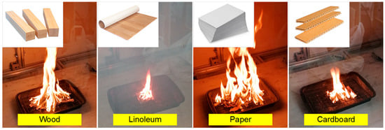
Figure 2.
Frames of combustion of model fires involving different materials.
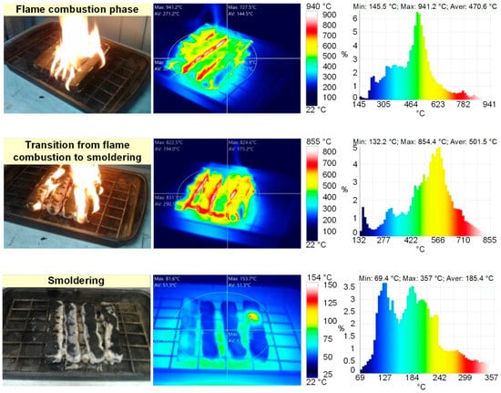
Figure 3.
Thermal images of model fire (wood) combustion (flame combustion phase; transition from flame combustion to smoldering; smoldering).
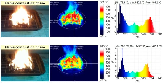

Figure 4.
Thermal images of model fire (linoleum) combustion (flame combustion; smoldering).
The analysis of thermal images (Figure 3 and Figure 4) revealed that the maximum temperatures of the fire involving wood were 940 °C during flame combustion and 350 °C during smoldering. The maximum temperatures of the fire involving linoleum were 945 °C during flame combustion and 350 °C during smoldering. The temperatures of the fires (the temperature of the fuel surface), consisting of paper and corrugated cardboard, were similar to those of the other two types of fires during combustion. During smoldering, the temperature of fires (the temperature of the fuel surface) consisting of paper and corrugated cardboard started falling almost immediately from 250–300 °C to 30–40 °C. The temperature of the fires (the temperature of the surface of the fuel in the model fire) hardly depends on the sizes and mass of the burning materials. The mass only affects the duration of the above stages. Figure 5 presents the thermocouple temperature trends (temperature versus time) in different parts of the SC during the combustion of the fires under study. The thermocouples TC#1 and TC#2 were mounted on the ceiling of the setup at a height of 1.25 m from the fire base. TC#3 and TC#4 were mounted on two opposite side walls of the SC. The height of positioning TC#3 and TC#4 was 0.3 m, and the distance to the fire center in the horizontal plane was 0.45 m.
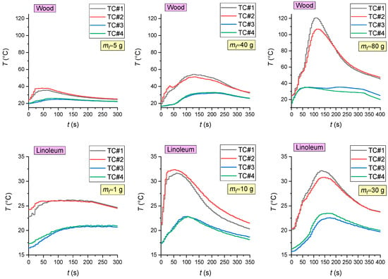
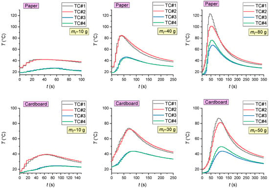
Figure 5.
The thermocouple temperature trends (temperature versus time) in different areas of the SC during the combustion of materials (wood; linoleum; paper; cardboard).
Figure 5 shows that the temperature in the control areas of the setup significantly depends on the mass of burning materials and thus on their heat release: the greater the model fire (the mass of burning materials), the higher the maximum gas temperatures. Using the obtained results, the heat flux densities were calculated: convective qconv (from the ambient gas medium to the fire), conductive qcond and radiant qrad (from the fire to the gas medium). The following formulas were used:
where α—convective heat transfer coefficient, W/(m2∙K); α = λg × Nu/Df; λg—thermal conductivity coefficient of gas, W/(m∙K); Nu—Nusselt number; Df—tentative diameter of the model fire, m; Tg—gas temperature, K; Tf—material temperature, °C; Nu = 2 + 0.6∙Re0.5∙Pr0.334; Re = Ug × Df/γ; Pr = γ × ρg × Cg/λg; σ = 5.67 × 10⁻⁸ W/(m2∙K4); Re—Reynolds number; Pr—Prandtl number; Ug—velocity of gas, m/s; Df—tentative diameter of the model fire, m; γ—kinematic viscosity, m/s2; ρg—gas density, kg/m3; Cg—heat capacity of gas, kg/m3.
qconv = α × (Tg − Tf);
qcond = λg × (Tf − Tg)/Df;
qrad = σ × εf × (Tf4 − Tg4),
The values of εf were taken in accordance with the main material in the fire: 0.91 for wood and linoleum and 0.96 for paper and cardboard [38,39,40]. When choosing λg, γ, ρg and Cg, the gas temperature was considered (Tg). The average temperature of the fuel surface during flame combustion, obtained from thermal images (Figure 3 and Figure 4), was taken as Tf. The natural convection velocity in the SC was taken as equal to 0.1 m/s. To determine the ranges of the heat flux changes, the initial gas temperature (20 °C) was used as Tg, and the temperatures determined following the experimental research were used (Figure 5): the maximum gas temperature in the upper part of the setup (TC#1, TC#2) and the maximum gas temperature near the lateral surface of the setup (TC#2, TC#3). The latter is accounted for by the non-uniform temperatures of the gas of the SC during the model fire combustion. In the final stage, the total specific heat flux (from the surface area unit of the model fire) was calculated (4):
qsum = qcond + qrad − qconv.
Figure 6 presents the total heat flux densities (qsum) during flame combustion when factoring in the actual maximum temperatures of the gas (Figure 5) of the SC (for different initial masses of burning materials).
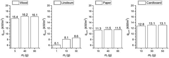
Figure 6.
Total heat flux (qsum) during flame combustion when factoring in the actual maximum temperatures of the gas of the SC (for different initial masses of burning materials).
Depending on the temperature Tg and the initial mass of the burning materials (mf), the heat fluxes may vary for different types of fires in the ranges presented in Table 4. It is clear that radiant heat exchange [41] makes a major contribution to total heat flux, which is typical of fires of different categories.

Table 4.
Variation ranges of specific heat flux densities for different types of fires.
The surface temperature of a model fire may differ across its perimeter. For a more accurate estimate, the surface temperature (Tf) of the model fire was defined as the arithmetic mean of the sample surface temperatures measured by the Testo-885 thermal imager (Figure 3 and Figure 4). The gas temperature and, hence, the temperature gradient also affect the heat fluxes. That is why, just as with the Tf, the Tg value used in the calculations was the average gas temperature (throughout the experiment) at a distance of 1 m above the model fire obtained by thermocouples. Thus, the calculated values of qsum are the average values that incorporate the nonlinearity and fluctuations in the temperature of the model fires of different initial masses and ambient gas.
The calculated heat flux values were compared with the data from [42,43,44]. Horvat et al. [42] presented research findings obtained using an experimental setup at CNRS-ENSMA-Poitiers. A 55 kW burner was used as the primary fire source. Three wood samples were made of beech with the dimensions 30 × 30 × 5 mm. The sample was heated using a gas burner. The total heat flux at the solid (wood)—gas interface was calculated with due consideration of the convective and radiant heat transfer to the environment. After ignition, the heat flux varied during the combustion of model fires in the range of 18–21 kW/m2 [42]. In the study [43], the sample was exposed to a radiant heat flux coming from an electrically heated conical coil. The distance between the sample and the heater was 25 mm. The samples were 50 mm-thick spruce wood pieces with the sizes 100 × 100 mm. The heat flux vector was perpendicular to the wood grain. To measure the temperature, thermocouples made of thin wire (0.1 mm in diameter) and sheathed thermocouples (1 mm in diameter) [43] were implanted deep into the samples. After that, the samples were heated using a cone calorimeter at different heat flux values (ranging from 16.5 kW/m2 to 93.5 kW/m2). The sample mass loss was additionally recorded during degradation. It was established [43] that the charring rate increases linearly from 0.5 mm/min s to 1 mm/min at heat fluxes of 16.5–93.5 kW/m2. Gollner et al. [44] measured the heat flux above the model fire (a class A plastic commodity packed in corrugated cardboard) 3 cm from the fire source using a thin-layer calorimeter. The total heat flux was determined as the sum of the radiant and convective heat fluxes above the fire. The maximum total heat flux found in the experiments [44] was approximately 5.3 kW/m2. The experimental research [45] was conducted using a wind tunnel as a setup with dimensions of 14 × 1.8 × 1.8 m (length × width × height). A stainless steel cuvette (1 × 1 × 0.57 m (length×width×height)) was placed along the central part of the tunnel. Cardboard was used as fuel. Laser-cut cardboard sheets (measuring 8 × 0.5 cm, with a thickness of 0.25 cm) were inserted into the cuvette channels to make up a fuel layer with the dimensions 0.9 × 0.4 × 0.08 m (length × width × depth). To measure the heat fluxes above the surface and inside the fuel layer [45], two pairs of water-cooled heat flux detectors by Medtherm and a radiant heat flux detector were used. The maximum total heat flux during the combustion of cardboard was found [45] to be approximately 11 kW/m2. Table 5 presents the results of the comparison of specific total heat fluxes obtained in this research with the values from [42,44,45] for paper and cardboard. The heat fluxes determined following the experiments in this research are consistent with the data of other studies, which shows the adequacy of the approach (Formulas (1)–(4)) proposed to qsum estimation.

Table 5.
Specific heat fluxes.
The experimental conditions in this research differ from those in [36,37,38,39]. The main objective of the qsum calculation and comparison against the findings from [36,37,38,39] was to compare the heat fluxes (Table 5). The total heat fluxes (Table 4) were calculated to show the difference between their values during the flame combustion and thermal decomposition of the various fuels. The heat fluxes presented in Table 4 can be successfully used for mathematical models simulating the conditions of small, closed spaces reproduced in the experiments in this research. The total heat release can be calculated as the multiplying of the total heat flux (qsum) by the area of the fire and the burning time: q’ = qsum × Sf × tf, kJ. The found values were: wood—197 kJ; paper—52 kJ; cardboard—94 kJ; and linoleum—75 kJ.
Figure 7 presents the experimental research findings obtained using GDS for the composition of gaseous products from the combustion of the materials under study (CO, CO2 and O2 concentrations in the SC during combustion and smoldering of model fires versus time). The Testo 340 gas analyzer did not measure the concentrations of CO2 and O2 for all the masses of the combustible materials under study (Figure 7). This result was conditioned by the response time of the O2 sensor (Table 3) of the Testo 340 gas analyzer. The analysis in Figure 7 shows the stages of sustained flame growth and combustion (characterized by an increase in the CO2 and CO concentrations, as well as by a decrease in O2), followed by the smoldering stage (characterized by a decrease in the CO2 concentrations, constant CO and slight growth of O2). This result is consistent with previously obtained temperature trends (Figure 5). It can be seen (Figure 7) that CO2 reaches its peak at the flame combustion stage. At the same time, the oxygen concentration is minimum, which indicates active oxidation. The flaming combustion stage is complete when the CO2 concentrations continue to fall, whereas the O2 concentrations increase. Smoldering begins when the CO yield becomes constant (Figure 7). The analysis in Figure 7 suggests that the type of fire and the mass of combustible materials are decisive factors for the duration and rate of the above-mentioned stages of model fire degradation.
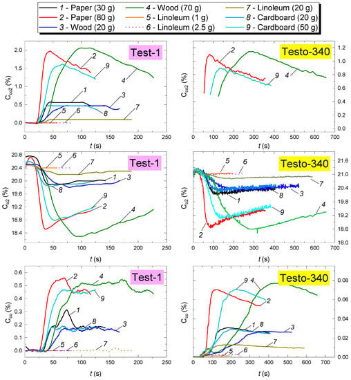
Figure 7.
CO, CO2 and O2 concentrations in the SC during combustion and smoldering of model fires versus time.
4.2. Numerical Simulation Results
Fire combustion with solid material in an enclosed space was simulated. A mathematical model to analyze the concentrations of CO, CO2, H2O, O2 and N2 during the combustion and thermal decomposition of typical combustible materials under study was developed using Ansys Fluent software. The scheme of the solution domain for heat transfer in the fire source—gas medium system with a mesh (80,694 elements, 80,032 nodes) is presented in Figure 8. The initial temperature in the solution domain T was taken as equal to 300 K. The flame temperature Tg was set to 1273 K. The oxidizer (O2) concentration at the initial point (t = 0) was assumed to be equal to the mass content of oxygen in the air (φO2 = 0.205). The computation was carried out on a 4-processor computer with a 3.4 GHz Intel Core i5-3570 CPU, 32 GB memory, 64K L1 cache, and 1MB L2 cache. The computation time ranged from 10 to 300 min.
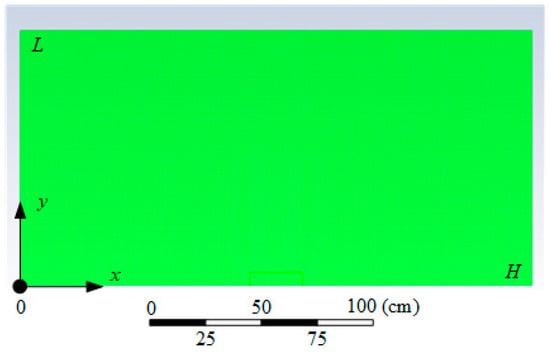
Figure 8.
Scheme of the solution domain for heat transfer in the fire source–gas medium system.
The interrelated processes of heat and mass transfer, as well as the physical and chemical transformations for the system under consideration (Figure 8), can be described by the following transient partial differential equations.
For the mixture of CO, CO2, H2O, O2, N2 (0 < x < H, 0 < y < L).
Continuity equation:
Equation of motion:
Energy equation:
Diffusion equation:
Balance equation:
where ψ—stream function, m2/s; x, y—coordinates of Cartesian system, m; ω—vorticity vector, s−1; u, v—combustible vapor velocity components projected to x, y axes; T—temperature, °C; 1—gas-vapor mixture; i—number of chemical reaction; γ—kinematic viscosity, m/s2; Q—thermal effect of chemical reaction, J/kg; W—mass rate of chemical reaction, kg/(m3·s); Ar—pre-exponential factor of chemical reaction, s−1; βr—exponent; Er—activation energy of chemical reaction, J/mol; Rt—universal gas constant, J/(mol·K); Cf—total mass concentration (proportion) of combustion products, %; ρ—density, kg/m3; D—diffusion coefficient, m2/s; CO2—mass concentration (proportion) of oxygen in the gas-vapor mixture, %; CCO—mass concentration of carbon monoxide in the gas-vapor mixture, %; CN2—mass concentration of nitrogen in the gas-vapor mixture, %; CH2O—mass concentration of water vapors in the gas-vapor mixture, %.
Table 6 presents the key chemical reactions that develop in the gas phase. Combustion products emitted from the surface of the fire source. The processes developing inside the fire were not taken into account.

Table 6.
Description of chemical reactions [46,47].
Volume fractions of the gas-vapor mixture components were derived from their mass concentrations:
The thermophysical characteristics of the gas-vapor mixture as a heterogeneous system were given by:
Initial conditions (t = 0): T = T0, CO2 = 1, Cf = 0, ψ = 0, ω = 0 when 0 < x < H, 0 < y < L.
Boundary conditions when t < 0:
T = Tg, CO2 = 0, Cf = 1 at the flame boundary.
Figure 9 presents the results of modeling the release of gaseous products of flame combustion and the thermal decomposition of wood, compared with the results of experimental studies.
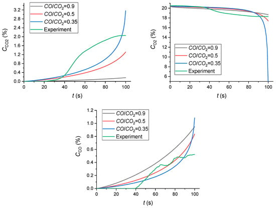
Figure 9.
Numerical simulation results (the release of gaseous products of flame combustion and thermal decomposition of wood compared with the results of experimental studies).
The numerical simulation results (Figure 7 and Figure 9) indicate that the calculated CO, CO2 and O2 concentrations are quite consistent with the experimental results (1.5–2% concentration of CO2 and 19–23% concentration of O2). The following specific aspect was established. In the mathematical modeling, the CO/CO2 concentration ratio is controlled by the CO/CO2 Split in Reaction Products that was set to 0.35–0.9 in accordance with the recommendations [48]. For a satisfactory correlation between the mathematical modeling results and the experimental data, the CO/CO2 ratio should be set as the source data. It is recommended to set the CO/CO2 Split in Reaction Products below 1 (about 0.35) for a satisfactory agreement with the experiment. As a result, not all the CO yielded in main chemical reaction 1 (Table 6) will be converted into CO2 due to the second chemical reaction. The developed mathematical model can be successfully used to determine the CO, CO2, H2O, O2 and N2 yields from the combustion and thermal decomposition of model fires. A comparison of the results of the numerical simulation with the experiment shows that the 2D model reliably predicts the nature of changes in gas concentrations over time. However, at the same time, quantitative differences at certain points can reach more than 15%. To develop more detailed models, it is necessary to consider other key factors, such as turbulent flow, non-stable boundary conditions, complex geometry of the objects, and the detailed kinetics of chemical reactions during pyrolysis, etc.
It is well known that 3D models are always better at simulating real physical processes [49,50,51,52,53]. However, the use of 3D models is always limited to the use of available computing equipment, particularly supercomputers [54,55]. Despite the popularity of supercomputers, 2D models are still important and allow calculations to be carried out on conventional personal computers. This, on the one hand, will allow any reader to reproduce the results of the presented calculations, and on the other hand, it is important for practical applications for engineers since the number of their calculations increases many times depending on the initial parameters. In our work, we have shown the possibility of using a 2D approach to model the complex physical phenomenon described in the article. The value of CO/CO2 = 0.35 was determined, at which a satisfactory agreement with the experimental data was obtained. This value corresponds to the typical values of CO/CO2 ≈ 0.4 for various fuels, including wood, described in [56].
4.3. Characteristics of Fire Detector Activation
The conducted cycle of experiments made it possible to identify the conditions of activation (including false alarms) of fire detectors (FD, HD, SD). Delays tD were shown to depend on a set of parameters and factors, which are presented in Table 7. The parameters and factors marked with “+” in Table 7 have a decisive effect on the detector performance characteristics; those marked with “−” have a weak effect on detector activation and response time. The effect of parameters and factors marked with “±” on the detector performance is unstable or indirect (e.g., for HD, the growth of the duration of combustion may contribute to the gas temperature increase, which is one of the decisive factors for this type of detector). More details on the factors listed in Table 7 are given below.

Table 7.
Parameters and factors affecting the activation and time of activation of different types of fire detectors (FD, HD, SD) (“+” affects; “−” has a minimal effect; “±” has a moderate effect).
In the experiments, two schemes of fire detector arrangement in the SC were used during the combustion of model fires consisting of wood. For other materials (linoleum, paper and cardboard), only Scheme #1 was considered. Figure 10 presents the top and side views of the experimental setup for each position of detectors (FD, HD and SD) under study.
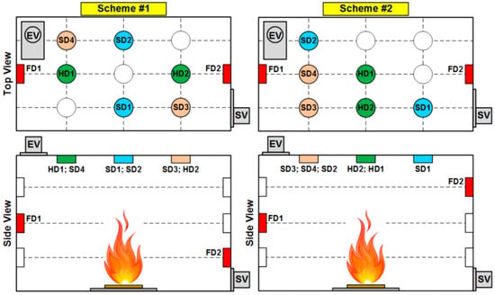
Figure 10.
Schemes of fire detector arrangement in the SC.
The choice of fire detector arrangement schemes (Figure 10) was based on the product specifications and installation guidelines. The aim was to consider schemes of fire detector arrangement that were principally different in terms of layout while meeting installation standards.
Figure 11 presents the curves of SD activation delay times versus the mass of the sample (material to be burned) for the combustion of wood, linoleum and cardboard. When the fire-containing paper was burning, SD was not activated in most of the experiments (with a mass of burning materials less than 50 g). It was established that the average activation time of wireless smoke detectors (SD# and SD4) during the combustion of wood is 26% lower than that of detectors connected though the circuit (SD1 and SD2) (153 s versus 208 s). In the combustion of fires involving linoleum, paper and cardboard, no differences in the detector response times were established (Figure 11).
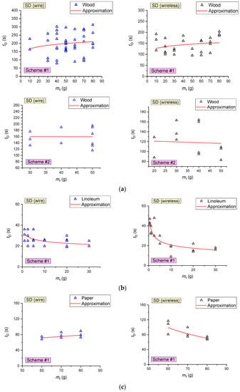
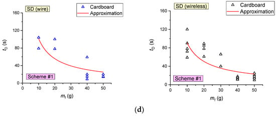
Figure 11.
Delay times of SD activation versus the sample mass during the combustion of wood (a), linoleum (b), paper (c) and cardboard (d).
Figure 12 presents the curves of FD activation delay times versus the mass of the sample (material to be burned) during the combustion of several types of model fires. It was established that FD activation times increase nonlinearly with the growth of the fuel’s initial mass. This result is attributed to the longer flame application with an increase in the sample mass. Additional experiments were conducted to confirm this conclusion, in which FD was turned on after the sustained flame growth of the model fire. The experiments revealed that the FD activation times during the stable combustion of materials (after flame application) did not depend on the mass of the fuel sample and varied in the range of 5–10 s.
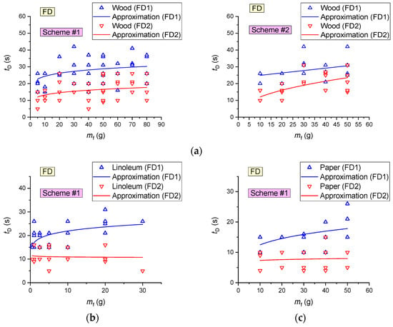
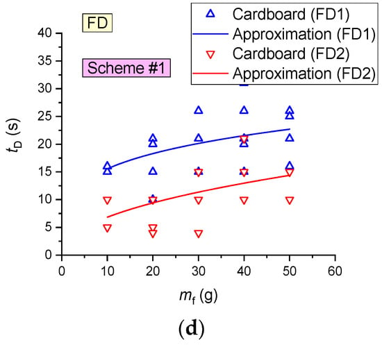
Figure 12.
FD activation delay times versus the sample mass during the combustion of wood (a), linoleum (b), paper (c) and cardboard (d).
Experiments involving wood fuel were conducted to evaluate the effect of the fire area on the characteristics of fire detector activation. Figure 13 presents the curves of the fire detectors (FD and SD) activation delay times versus the fire area (Sf) during the combustion of wood (mass of burning materials mf ≈ 50 g). An increase in the fire area Sf (as illustrated by wood) in the range of 100–260 cm2 (at a constant mass of the burning materials) was established to increase the time of FD activation by 45–50% (6–12 s). This is obviously related to an increase in the flame application time when the fire area increases. The SD activation times were recorded to decrease by 45–55% (Figure 13) with the fire area increase in the range of 100–260 cm2 (at a constant mass of the burning materials).
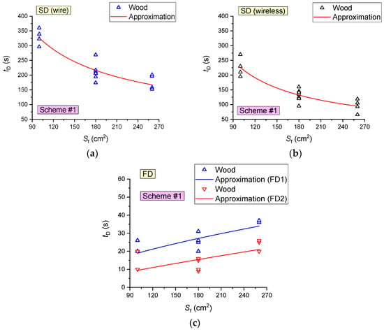
Figure 13.
Fire detector (FD and SD) activation delay times versus the fire area during wood combustion (mass of burning materials 50 g): (a) SD1, SD2; (b) SD3, SD4; (c) FD.
FD activation delays during wood combustion versus the flame height and detector position are shown in Figure 14. The activation time of different FD (of the same brand) was found to differ by 5–6 s under the same conditions. The experiments also show that the FD activation delay times (in the event of its activation) do not depend on the flame height, height of detector position or distance of the detector from the fire (Figure 14).
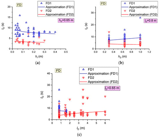
Figure 14.
FD activation time during wood combustion versus flame height (a), height of detector position (b) and distance of detectors from the fire (c).
Following the experiments, a summary map of FD activation/activation failure, shown in Figure 15, was plotted.
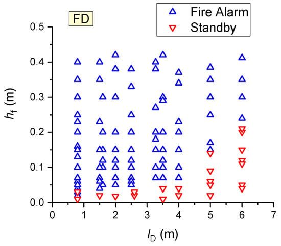
Figure 15.
Summary map of FD activation/activation failure (all the results obtained during wood combustion were used).
The results obtained during wood combustion were used (Figure 15). It was established that at a flame height of 1–2 cm, the FDs employed in the experiments were not activated in most cases. When the flame detector was moved away to a distance of 1–6 m from the fire, the flame height necessary for detector activation was found to increase nonlinearly to 2–25 cm. Overall, the experimental findings indicate that the constructed map for detector activation/activation failure (Figure 15) should be applied to predict FD activation.
Since the decisive factors for HD activation (Table 7) were the gas temperature and its increase rate, the maps of activation/activation failure plotted to evaluate the characteristics of HD activation took the effect of these factors into account (Figure 16). The experiments revealed that the most practical position of HD is right above the fire source (Figure 10, Scheme #2, detector HD1). Despite the rate of the gas temperature rise specified for this HD detector (0.05–0.5 °C/s), the heat detector was usually activated in the experiments conducted at a rate of temperature rise of at least 0.5–0.6 °C/s (Figure 16). Figure 17 presents a summary map of HD activation/activation failure.
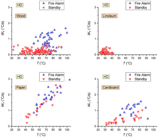
Figure 16.
Maps of HD activation/activation failure during the combustion of fuel materials (wood; linoleum; paper; cardboard).
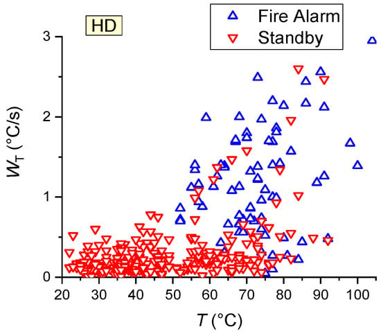
Figure 17.
Summary map of HD activation/activation failure (all the results obtained during wood, linoleum, paper and cardboard combustion were used).
- During paper combustion, the rapid growth followed by the subsequent reduction in the temperature led to HD activation failure in 42% of cases (Figure 16), even at high rates of temperature rise (more than 1 °C/s);
Figure 18 presents the average activation delay times of detectors, determined from the results of a cycle of experiments (for all the combustible materials under study).
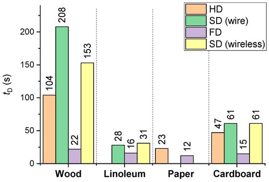
Figure 18.
Average activation delay times of detectors (FD, HD, SD) derived from a cycle of experiments (for all the combustible materials under study).
It is clear (Figure 18) that the lowest average activation times (12–16 s) of FD were recorded for paper, cardboard and linoleum, which is apparently related to the low (as compared to wood, e.g.,) time of sustained flame growth of the model fire (at an identical mass of the fuel sample). The maximum tD for SD corresponds to wood, the average values correspond to cardboard, and the minimum values are typical of linoleum.
The size of the fire source affects the flame turbulence regime, diffusion rate, and formation of combustion products. The heat flux and, hence, the temperature of a turbulent flame (large fire source) will exceed those of a laminar flame. As a result, HDs will give an “Fire Alarm” signal earlier (see a summary map of HD activation/activation failure in Figure 17). This factor had a negligible effect on the SD and FD activation response times (Figure 18).
Figure 19 presents the experimentally obtained curves of the probability of detector (FD, HD, SD) activation (P) versus the mass of the samples during the combustion of the four fuels considered in the experiments.
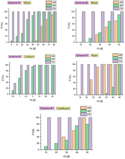
Figure 19.
Probability of detector (FD, HD, SD) activation at different masses of the sample during the combustion of fuel materials (wood; linoleum; paper; cardboard).
The overall probability (Figure 19) of each detector type activation was calculated as an arithmetic mean of the probability of detector (FD, HD, SD) activation in each experiment: P = (P1 + P2 + …+ Pj)/j. The detector activation probability in the experiment was calculated as a ratio of the number of activated detectors to the total number of detectors (Pj = na/nD∙100%).
The analysis of the probability of FD, HD and SD activation (Figure 19) led to the following conclusions:
- The probability of SD activation during the combustion of cardboard (with a mass below 30 g) is less than 20%. In the combustion of cardboard with a mass exceeding 40 g, the probability of SD activation was 70–80% (Figure 19);
- The probability of SD activation during the combustion of 1 g fabric-backed linoleum was approximately 50%. During the combustion of linoleum with a mass of 5 g and above, the probability of SD activation reached 100% (Figure 19). This result can be explained by the intense smoke emissions of the material. At the same time, smoke particles emitted by linoleum absorb and scatter light in a wide range of wavelengths [57]. For this reason, the detectors respond quickly;
- The probability of SD activation is mainly conditioned by the type of combustible material (Figure 19);
- SDs are most effective when detecting fires involving linoleum (average detection time 28–31 s), cardboard (61 s) and wood (153–208 s);
- In the experiments conducted with the fire source located in the SC, FDs were activated in 100% cases for all the combustible materials under study (Figure 19);
- The event of HD activation is primarily conditioned by the temperature of the gas and its growth rate (Figure 17), though the analysis in Figure 19 reveals that these parameters are indirectly affected by the mass of the sample involved in the model fire. An increase in mf contributes to faster HD activation (Figure 19).
Figure 20 presents the average SD activation delay times during the combustion of wood for the two schemes under consideration (Figure 10). It is clear from Figure 20 that it is most practical to mount SD in the corner points of the ceiling. As illustrated by wired detectors connected though the circuit, it was established that the time of fire detection in this case (Scheme #2) is 20% lower than when detectors are fitted along the wall (Scheme #1). Exhaust ventilation (in the case of the natural draft) was also found to reduce the time of fire detection by 7–12% (Figure 20) if SD was placed nearby.
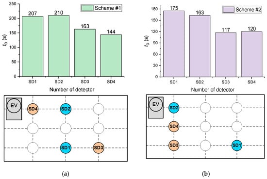
Figure 20.
Average SD activation times during the combustion of wood for the two schemes under consideration: (a) Scheme #1; (b) Scheme #2.
Experiments were conducted to evaluate the effect of the smoke ventilation system and air humidity (CH2O) on the characteristics of fire detector (FD, HD, SD) activation. With this end in view, the EV was turned on in the experiments; an ultrasonic mist maker and a steam generator were used, and the humidity was measured with a Testo 608-H1 hydrometer. It was experimentally established that these factors affect the characteristics of SD and HD activation. FD performance was not influenced by these factors. Figure 21 presents the results obtained for SD.
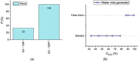
Figure 21.
(a) Effect of smoke ventilation system on SD activation probability during wood combustion (sample mass 50 g); (b) Influence of air humidity on false alarms of smoke detectors (the experiments were conducted using an ultrasonic water mist maker; a Testo hydrometer was used).
The following conclusions were drawn:
- With EV switched on and under otherwise identical conditions, the probability of SD activation decreases threefold (from 100% to 33% at the initial 100% activation) (Figure 21);
- Air humidity over 85–90% leads to false alarms of all the SD types under study (which was established in the experiments utilizing an ultrasonic water mist maker) (Figure 21). When the air humidity reaches 85–90%, the detectors are activated in 4–7 s on average;
- When a steam generator (producing hot water steam) is placed under SD (at a distance of 0.5–1 m), the detector is activated only when there is condensation (short circuit) on it in 11–12 min after the generator starts working;
- When HD is exposed to hot water steam, the detector is activated when the temperature in its vicinity reaches 63–75 °C.
Based on the results of the experiments, we additionally generalized the data (mass of materials, times and probabilities of activation of the detectors), which illustrates the characteristics of the fire detectors (Figure 22).
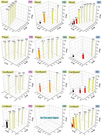
Figure 22.
Generalized performance characteristics of fire detectors (FD, HD, SD) for the four combustible materials.
It was also established that sunflecks can often cause false SD alarms. At the same time, no false alarms of flame detectors were induced by direct and targeted exposure to a light flow (using a 1500 W halogen spotlight).
The effect of a combination of model fire materials on SD activation characteristics was also explored. Figure 23 presents the probability and delay of SD activation for different combinations of combustible materials. It is clear (Figure 23) that in a mixed-model fire, the overall probability of SD activation is 15–30% higher than the sum of the probabilities of SD activation when a single material is burned. This specific aspect must be considered in fire detection system engineering.
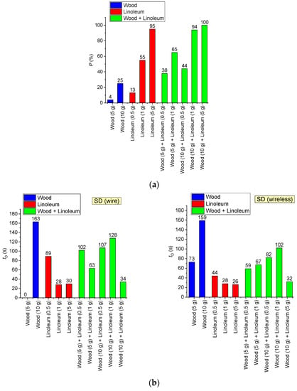
Figure 23.
Probability (a) and delay (b) of SD activation for different combinations of combustible materials.
Figure 24 presents a map of the SD activation probability versus the mass of linoleum and wood in a mixed fire. Figure 23 shows that the resulting probability of SD activation highly depends on the fuel mass ratio. At the same time, according to Figure 24, if a fuel has a certain threshold mass (50 g for wood and 10 g for linoleum), it will provide a 100% detector activation probability. If any other fuel is added to the fuel with the “threshold mass” in any proportion, the values of P will not change.
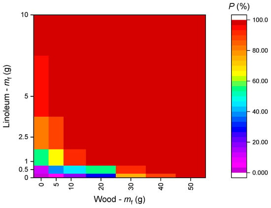
Figure 24.
Probability of SD activation vs. mass of linoleum and wood (when several fuels are involved in a model fire).
Figure 25 presents a curve of the probability of smoke detector activation versus the concentrations of smoke aerosol and pyrolysis products in the SC.
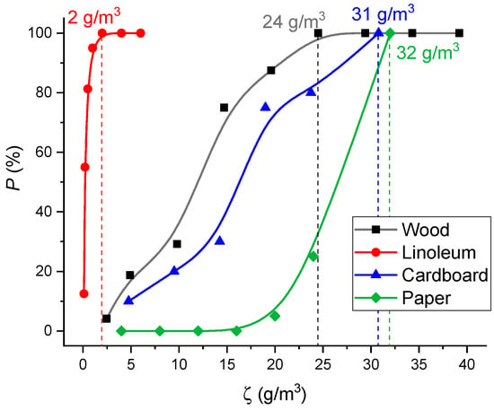
Figure 25.
Probability of SD activation versus concentrations of smoke aerosol and pyrolysis products in the SC (for different materials).
To obtain the curves presented in Figure 25, the fuels burned in a model fire were weighed on a laboratory microbalance before the start of the experiment and after it was completed. The mass loss of burning materials (Δmf) during the experiment was determined. The lost mass Δmf was assumed to turn into pyrolysis and combustion products. The ratio of the mass loss to the volume of the SC ζ was determined. The probability of SD activation was taken in accordance with Figure 19. The concentrations of smoke aerosol and pyrolysis products sufficient for SD activation were determined (Figure 19). Under real fire conditions, the fuel combustion rate may differ by an order of magnitude or more, depending on the ignition mechanism. SD activation can be predicted at a first approximation using the mass concentrations presented in Figure 24, irrespective of the fuel ignition and thermal decomposition regime.
5. Conclusions
Thus, the behavior of a typical compartment fire at the stages of ignition and combustion development was determined. The main stages of model fire combustion were singled out. The stages can be identified by the change in thermocouple trends and by gas analysis: the stages of sustained flame growth and combustion are characterized by a rise in CO2 and CO concentrations, a decrease in O2 concentrations and an increase in the ambient temperature; smoldering is characterized by lower CO2, constant CO, a slight rise in O2 and a decrease in the ambient temperature. At the flame combustion stage, the total heat flux from the fires of different types was found to be up to 16.6 kW/m2 for wood, 8.6 kW/m2 for linoleum, 12 kW/m2 for class A paper and 13.5 kW/m2 for corrugated cardboard.
The following key conclusions and recommendations were made from the research findings:
- Decisive parameters for effective heat detector activation were the rate of air temperature rise, air temperature, and time that the air temperature remained sufficient for the detector to respond;
- The minimum temperature threshold for heat detector activation was 50–55 °C (at a rate of temperature rise 0.7–0.8 °C/s);
- During paper combustion, fast growth of temperature followed by its reduction led to HD activation failure in approximately 42% of cases even at high rates of temperature rise (more than 1 °C/s) and high air temperatures (over 55–60 °C);
- The most practical location of a heat detector (providing the fastest fire detection) was right above the fire;
- When a fire is located within the visual range of a flame detector, it responds to flame in 100% cases for all the combustible materials under study;
- During steady combustion of a fire (after the appearance of the flame), flame detector response time did not depend on the fuel sample mass;
- When the flame detector is moved to a distance of 1–6 m from the fire, the flame height necessary for the detector activation increased nonlinearly to 2–25 cm;
- The probability of smoke detector activation for all the combustible materials under study increased with an increase in fuel sample mass. Smoke detector activation times decreased with an increase in the mass of the combustible material;
- Smoke detectors were most effective for linoleum combustion detection;
- Smoke detectors were most effective when mounted at the corner points of the ceiling. As illustrated by wired detectors connected though the circuit, the time of fire detection in this case is 20% lower than when detectors are fitted along the wall;
- With the smoke ventilation system turned on and under otherwise identical conditions, the probability of smoke detector activation decreases threefold.
Author Contributions
A.Z., writing—original draft preparation of manuscript; R.V., planning and conducting experiments; A.S., conducting pilot studies; G.K., conceptualization, funding acquisition; P.S., writing—original draft. All authors have read and agreed to the published version of the manuscript.
Funding
This research was supported by the Russian Science Foundation (project No. 21-19-00009, https://rscf.ru/en/project/21-19-00009/, accessed on 1 June 2022).
Conflicts of Interest
The authors declare no conflict of interest.
Nomenclature
| a | Temperature conductivity, m2/s |
| Ar | Pre-exponential factor of chemical reaction, s−1 |
| Cg | Heat capacity of gas, kg/m3 |
| CCO | Mass concentration (proportion) of carbon monoxide in the gas-vapor mixture, % |
| CCO2 | Mass concentration (proportion) of carbon dioxide in the gas-vapor mixture, % |
| Cf | Total mass concentration (proportion) of combustion products, % |
| CH2O | Mass concentration (proportion) of water vapors in the gas-vapor mixture, % |
| CN2 | Mass concentration (proportion) of nitrogen in the gas-vapor mixture, % |
| CO2 | Mass concentration (proportion) of oxygen in the gas-vapor mixture, % |
| D | Diffusion coefficient, m2/s |
| Df | Tentative diameter of model fire, m |
| Er | Activation energy of chemical reaction, J/mol |
| hD | Optical flame detector mounting height relative to the model fire base, m |
| hf | Height of model fire flame, m |
| H, L | Sizes of the solution domain projected to x and y axes, m |
| j | Number of experiments in a set |
| lD | Distance from the optical flame detector to the model fire, m |
| mf | Mass of materials to be burned (g) |
| na | Number of detectors of a particular type, activated in the experiment |
| nD | Total number of detectors of a particular type in the experiment |
| Nu | Nusselt number |
| P | Overall probability of activation of each type of detectors, % |
| P1, P2, …, Pj | Probability of detector activation in each experiment, % |
| Pr | Prandtl number |
| qcond | Conductive heat flux, kW/m2 |
| qconv | Convective heat flux, kW/m2 |
| qrad | Radiant heat flux, kW/m2 |
| qsum | Total heat flux, kW/m2 |
| q’ | Total heat release, kJ |
| Q | Thermal effect of chemical reaction, J/kg |
| Rt | Universal gas constant, J/(mol·K) |
| Re | Reynolds number |
| Sf | Surface areas of model fire (cm2) |
| t | Time, s |
| tD | Fire detector activation time, s |
| tf | Time of complete burnout of model fire, s |
| T | Temperature, °C |
| Tf | Temperature of model fire surface, °C |
| Tg | Gas temperature, K |
| u, v | Combustible vapor velocity components projected to x, y axes, m/s |
| Ug | Velocity (of free convection) of gas, m/s |
| W | Mass rate of chemical reaction, kg/(m3·s) |
| WT | Rate of gas temperature rise, °C/s |
| x, y | Coordinates of Cartesian system, m |
| Subscripts | |
| 1 | Gas-vapor mixture |
| i | Number of chemical reaction |
| Greek | |
| α | Convective heat transfer coefficient, W/(m2∙K) |
| βr | Exponent |
| γ | Kinematic viscosity, m/s2 |
| Δmf | Loss of mass of burning material during experiment (material pyrolysis), g |
| λg | Thermal conductivity coefficient of gas, W/(m∙K) |
| ρ | Density, kg/m3 |
| ρg | Gas density, kg/m3 |
| ψ | Stream function, m2/s |
| ω | Vorticity vector, s−1 |
| ζ | Concentration of smoke aerosol and pyrolysis products, g/m3 |
| Abbreviations | |
| DAIM | Digital and analog input module |
| EV | Exhaust ventilation |
| FACD | Fire alarm control device |
| FD | Flame detector |
| GDS | Gas detection system |
| HD | Heat detector |
| SC | Setup chamber |
| SD | Smoke detector |
| SV | Supply ventilation |
| TC | Thermocouple |
| FAC | Fire alarm circuit |
References
- Araujo Lima, G.P.; Viana Barbosa, J.D.; Beal, V.E.; Marcelo, M.A.; Souza Machado, B.A.; Gerber, J.Z.; Lazarus, B.S. Exploratory Analysis of Fire Statistical Data and Prospective Study Applied to Security and Protection Systems. Int. J. Disaster Risk Reduct. 2021, 61, 102308. [Google Scholar] [CrossRef]
- Brushlinsky, N.N.; Ahrens, M.; Sokolov, S.V. World Fire Statistics. 2020. Available online: https://www.ctif.org/sites/default/files/2020-06/CTIF_Report25.pdf (accessed on 1 May 2022).
- Shams Abadi, S.T.; Moniri Tokmehdash, N.; Hosny, A.; Nik-Bakht, M. BIM-Based Co-Simulation of Fire and Occupants’ Behavior for Safe Construction Rehabilitation Planning. Fire 2021, 4, 67. [Google Scholar] [CrossRef]
- Nazir, A.; Mosleh, H.; Takruri, M.; Jallad, A.H.; Alhebsi, H. Early Fire Detection: A New Indoor Laboratory Dataset and Data Distribution Analysis. Fire 2022, 5, 11. [Google Scholar] [CrossRef]
- Ding, Z.; Zhao, Y.; Li, A.; Zheng, Z. Spatial–Temporal Attention Two-Stream Convolution Neural Network for Smoke Region Detection. Fire 2021, 4, 66. [Google Scholar] [CrossRef]
- GOST 12.1.044–89*; Occupational Safety Standards System. Fire and Explosion Hazard of Substances and Materials. Nomenclature of Indices and Methods of Their Determination. Standardinform: Moscow, Russia, 1991.
- Bu, F.; Gharajeh, M.S. Intelligent and Vision-Based Fire Detection Systems: A Survey. Image Vis. Comput. 2019, 91, 103803. [Google Scholar] [CrossRef]
- Wu, H.; Wu, D.; Zhao, J. An Intelligent Fire Detection Approach through Cameras Based on Computer Vision Methods. Process Saf. Environ. Prot. 2019, 127, 245–256. [Google Scholar] [CrossRef]
- Hashemzadeh, M.; Zademehdi, A. Fire Detection for Video Surveillance Applications Using ICA K-Medoids-Based Color Model and Efficient Spatio-Temporal Visual Features. Expert Syst. Appl. 2019, 130, 60–78. [Google Scholar] [CrossRef]
- Khatami, A.; Mirghasemi, S.; Khosravi, A.; Lim, C.P.; Nahavandi, S. A New PSO-Based Approach to Fire Flame Detection Using K-Medoids Clustering. Expert Syst. Appl. 2017, 68, 69–80. [Google Scholar] [CrossRef]
- Hagen, B.C.; Meyer, A.K. From Smoldering to Flaming Fire: Different Modes of Transition. Fire Saf. J. 2021, 121, 103292. [Google Scholar] [CrossRef]
- Zhou, Y.; Bu, R.; Gong, J.; Zhang, X.; Fan, C.; Wang, X. Assessment of a Clean and Efficient Fire-Extinguishing Technique: Continuous and Cycling Discharge Water Mist System. J. Clean. Prod. 2018, 182, 682–693. [Google Scholar] [CrossRef]
- Zhang, X.; Zhang, Z.; Su, G.; Tang, F.; Liu, A.; Tao, H. Experimental Study on Thermal Hazard and Facade Flame Characterization Induced by Incontrollable Combustion of Indoor Energy Usage. Energy 2020, 207, 118173. [Google Scholar] [CrossRef]
- Qin, R.; Zhou, A.; Chow, C.L.; Lau, D. Structural Performance and Charring of Loaded Wood under Fire. Eng. Struct. 2021, 228, 111491. [Google Scholar] [CrossRef]
- Schmid, J.; Brandon, D.; Werther, N.; Klippel, M. Technical Note—Thermal Exposure of Wood in Standard Fire Resistance Tests. Fire Saf. J. 2019, 107, 179–185. [Google Scholar] [CrossRef]
- Zhou, Z.; Wei, Y.; Li, H.; Yuen, R.; Jian, W. Experimental Analysis of Low Air Pressure Influences on Fire Plumes. Int. J. Heat Mass Transf. 2014, 70, 578–585. [Google Scholar] [CrossRef] [Green Version]
- Mitrenga, P.; Osvaldová, L.M.; Marková, I. Observation of Fire Characteristics of Selected Covering Materials Used in Upholstered Seats. Transp. Res. Procedia 2021, 55, 1775–1782. [Google Scholar] [CrossRef]
- Zhang, Y.; Yang, X.; Luo, Y.; Gao, Y.; Liu, H.; Li, T. Experimental Study of Compartment Fire Development and Ejected Flame Thermal Behavior for a Large-Scale Light Timber Frame Construction. Case Stud. Therm. Eng. 2021, 27, 101133. [Google Scholar] [CrossRef]
- Hao, H.; Chow, C.L.; Lau, D. Effect of Heat Flux on Combustion of Different Wood Species. Fuel 2020, 278, 118325. [Google Scholar] [CrossRef]
- Diab, M.T.; Haelssig, J.B.; Pegg, M.J. The Behaviour of Wood Crib Fires under Free Burning and Fire Whirl Conditions. Fire Saf. J. 2020, 112, 102941. [Google Scholar] [CrossRef]
- Tao, L.; Zeng, Y. Effect of Different Smoke Vent Layouts on Smoke and Temperature Distribution in Single-Side Multi-Point Exhaust Tunnel Fires: A Case Study. Fire 2022, 5, 28. [Google Scholar] [CrossRef]
- Qiu, X.; Wei, Y.; Li, N.; Guo, A.; Zhang, E.; Li, C.; Peng, Y.; Wei, J.; Zang, Z. Development of an Early Warning Fire Detection System Based on a Laser Spectroscopic Carbon Monoxide Sensor Using a 32-Bit System-on-Chip. Infrared Phys. Technol. 2019, 96, 44–51. [Google Scholar] [CrossRef]
- Li, Y.Z.; Ingason, H. Influence of Fire Suppression on Combustion Products in Tunnel Fires. Fire Saf. J. 2018, 97, 96–110. [Google Scholar] [CrossRef] [Green Version]
- Pan, W.; Zhang, M.; Gao, X.; Mo, S. Establishment of Aqueous Film Forming Foam Extinguishing Agent Minimum Supply Intensity Model Based on Experimental Method. J. Loss Prev. Process Ind. 2020, 63, 103997. [Google Scholar] [CrossRef]
- Bustamante Valencia, L.; Rogaume, T.; Guillaume, E.; Rein, G.; Torero, J.L. Analysis of Principal Gas Products during Combustion of Polyether Polyurethane Foam at Different Irradiance Levels. Fire Saf. J. 2009, 44, 933–940. [Google Scholar] [CrossRef] [Green Version]
- Bluvshtein, N.; Villacorta, E.; Li, C.; Hagen, B.C.; Frette, V.; Rudich, Y. Early Detection of Smoldering in Silos: Organic Material Emissions as Precursors. Fire Saf. J. 2020, 114, 103009. [Google Scholar] [CrossRef]
- Noaki, M.; Delichatsios, M.A.; Yamaguchi, J.; Ohmiya, Y. Heat Release Rate of Wooden Cribs with Water Application for Fire Suppression. Fire Saf. J. 2018, 95, 170–179. [Google Scholar] [CrossRef]
- Gorska, C.; Hidalgo, J.P.; Torero, J.L. Fire Dynamics in Mass Timber Compartments. Fire Saf. J. 2021, 120, 103098. [Google Scholar] [CrossRef]
- Östman, B.; Brandon, D.; Frantzich, H. Fire Safety Engineering in Timber Buildings. Fire Saf. J. 2017, 91, 11–20. [Google Scholar] [CrossRef] [Green Version]
- Onorati, T.; Malizia, A.; Diaz, P.; Aedo, I. Modeling an Ontology on Accessible Evacuation Routes for Emergencies. Expert Syst. Appl. 2014, 41, 7124–7134. [Google Scholar] [CrossRef] [Green Version]
- Wagner, N.; Agrawal, V. An Agent-Based Simulation System for Concert Venue Crowd Evacuation Modeling in the Presence of a Fire Disaster. Expert Syst. Appl. 2014, 41, 2807–2815. [Google Scholar] [CrossRef]
- GOST R 51032–97; Building Materials. Spread Flame Test Method. Standardinform: Moscow, Russia, 1997.
- Lowden, L.A.; Hull, T.R. Flammability Behaviour of Wood and a Review of the Methods for Its Reduction. Fire Sci. Rev. 2013, 2, 4. [Google Scholar] [CrossRef] [Green Version]
- Log, T. Cold Climate Fire Risk; A Case Study of the Lærdalsøyri Fire, January 2014. Fire Technol. 2016, 52, 1825–1843. [Google Scholar] [CrossRef] [Green Version]
- Toscano, G.; Leoni, E.; Gasperini, T.; Picchi, G. Performance of a Portable NIR Spectrometer for the Determination of Moisture Content of Industrial Wood Chips Fuel. Fuel 2022, 320, 123948. [Google Scholar] [CrossRef]
- Park, J.; Kwark, J. Experimental Study on Fire Sources for Full-Scale Fire Testing of Simple Sprinkler Systems Installed in Multiplexes. Fire 2021, 4, 8. [Google Scholar] [CrossRef]
- GOST R 54081-2010 (MEK 60721-2-8:1994); Influence of Environmental Conditions Appearing in Nature on the Technical Products. Overall Performance Fire. Standardinform: Moscow, Russia, 2011.
- Pitarma, R.; Crisóstomo, J. Determination of Wood Emissivity Using Active Infrared Thermography. In Environmental Science and Engineering; Springer: Berlin/Heidelberg, Germany, 2021. [Google Scholar]
- Touloukian, Y.S.; Powell, R.W.; Ho, C.Y.; Klemens, P.G. Thermophysical Properties of Matter—The TPRC Data Series; Thermophysical and Electronic Properties Information Center: Lafayette, IN, USA, 1975. [Google Scholar]
- Yakimovich, K.A. Thermophysical Properties of Materials. Phys. Technol. 1977, 8, 35–36. [Google Scholar] [CrossRef] [Green Version]
- Kuznetsov, G.V.; Piskunov, M.V.; Volkov, R.S.; Strizhak, P.A. Unsteady Temperature Fields of Evaporating Water Droplets Exposed to Conductive, Convective and Radiative Heating. Appl. Therm. Eng. 2018, 131, 340–355. [Google Scholar] [CrossRef]
- Horvat, A.; Sinai, Y.; Pearson, A.; Most, J.M. Contribution to Flashover Modelling: Development of a Validated Numerical Model for Ignition of Non-Contiguous Wood Samples. Fire Saf. J. 2009, 44, 779–788. [Google Scholar] [CrossRef]
- Terrei, L.; Acem, Z.; Marchetti, V.; Lardet, P.; Boulet, P.; Parent, G. In-Depth Wood Temperature Measurement Using Embedded Thin Wire Thermocouples in Cone Calorimeter Tests. Int. J. Therm. Sci. 2021, 162, 106686. [Google Scholar] [CrossRef]
- Gollner, M.J.; Overholt, K.; Williams, F.A.; Rangwala, A.S.; Perricone, J. Warehouse Commodity Classification from Fundamental Principles. Part I: Commodity & Burning Rates. Fire Saf. J. 2011, 46, 305–316. [Google Scholar] [CrossRef]
- He, Q.; Liu, N.; Xie, X.; Zhang, L.; Zhang, Y.; Yan, W. Experimental Study on Fire Spread over Discrete Fuel Bed-Part I: Effects of Packing Ratio. Fire Saf. J. 2021, 126, 103470. [Google Scholar] [CrossRef]
- Vershinina, K.; Shabardin, D.; Strizhak, P. Burnout Rates of Fuel Slurries Containing Petrochemicals, Coals and Coal Processing Waste. Powder Technol. 2019, 343, 204–214. [Google Scholar] [CrossRef]
- Glushkov, D.O.; Lyrshchikov, S.Y.; Shevyrev, S.A.; Strizhak, P.A. Burning Properties of Slurry Based on Coal and Oil Processing Waste. Energy Fuels 2016, 30, 3441–3450. [Google Scholar] [CrossRef]
- Ansys Fluent Theory Guide Ansys Fluent Theory Guide; ANSYS Inc.: Canonsburg, PA, USA, 2021.
- You, J.; Huai, Y.; Nie, X.; Chen, Y. Real-Time 3D Visualization of Forest Fire Spread Based on Tree Morphology and Finite State Machine. Comput. Graph. 2022, 103, 109–120. [Google Scholar] [CrossRef]
- Frangieh, N.; Accary, G.; Rossi, J.L.; Morvan, D.; Meradji, S.; Marcelli, T.; Chatelon, F.J. Fuelbreak Effectiveness against Wind-Driven and Plume-Dominated Fires: A 3D Numerical Study. Fire Saf. J. 2021, 124, 103383. [Google Scholar] [CrossRef]
- Konovalov, I.B.; Golovushkin, N.A.; Beekmann, M.; Andreae, M.O. Insights into the Aging of Biomass Burning Aerosol from Satellite Observations and 3D Atmospheric Modeling: Evolution of the Aerosol Optical Properties in Siberian Wildfire Plumes. Atmos. Chem. Phys. 2021, 21, 357–392. [Google Scholar] [CrossRef]
- Tavakolian, Z.; Abouali, O.; Yaghoubi, M. 3D Simulations of Smoke Exhaust System in Two Types of Subway Station Platforms. Int. J. Vent. 2021, 20, 65–81. [Google Scholar] [CrossRef]
- Bao, T.; Liu, S.; Qin, Y.; Liu, L.Z. 3D Modeling of Coupled Soil Heat and Moisture Transport beneath a Surface Fire. Int. J. Heat Mass Transf. 2020, 149, 119163. [Google Scholar] [CrossRef]
- Baranovskiy, N.V. Algorithms for Parallelizing a Mathematical Model of Forest Fires on Supercomputers and Theoretical Estimates for the Efficiency of Parallel Programs. Cybern. Syst. Anal. 2015, 51, 471–480. [Google Scholar] [CrossRef]
- Li, J.; Li, X.; Chen, C.; Zheng, H.; Liu, N. Three-Dimensional Dynamic Simulation System for Forest Surface Fire Spreading Prediction. Int. J. Pattern Recognit. Artif. Intell. 2018, 32, 1850026. [Google Scholar] [CrossRef]
- Hurley, M.J.; Gottuk, D.; Hall, J.R.; Harada, K.; Kuligowski, E.; Puchovsky, M.; Torero, J.; Watts, J.M.; Wieczorek, C. Handbook of Fire Protection Engineering, 5th ed.; SFPE: Quincy, MA, USA, 2016; ISBN 9781493925650. [Google Scholar]
- Zhdanova, A.O.; Volkov, R.S.; Kuznetsov, G.V.; Kopylov, N.P.; Kopylov, S.N.; Syshkina, E.Y.; Strizhak, P.A. Solid particle deposition of indoor material combustion products. Process Saf. Environ. Prot. 2022, 162, 494–512. [Google Scholar] [CrossRef]
Publisher’s Note: MDPI stays neutral with regard to jurisdictional claims in published maps and institutional affiliations. |
© 2022 by the authors. Licensee MDPI, Basel, Switzerland. This article is an open access article distributed under the terms and conditions of the Creative Commons Attribution (CC BY) license (https://creativecommons.org/licenses/by/4.0/).