Article

Experimental and Numerical Study of the Trench Fire Spread Rule over a Sloped Uniform Fuel Bed: Rate of Fire Spread, Flame Morphology, and Heat Flux

School of Resource and Safety Engineering, Central South University, Changsha 410083, China
*
Author to whom correspondence should be addressed.
Fire 2023, 6(12), 469; https://doi.org/10.3390/fire6120469
Submission received: 13 October 2023 / Revised: 1 December 2023 / Accepted: 12 December 2023 / Published: 14 December 2023

Abstract

:
Trench fires on sloped terrain are always complicated due to the corresponding flame dynamics and heat transfer mechanisms. Flame attachment may increase the rate of fire spread (ROS) by enlarging the heating area of unburned vegetation. In addition, variations in radiative and convective heat flux are of great importance to fire behavior characteristics. In this work, trench fire tests under different slopes (θ) and inclined sidewalls (A) were performed by numerical simulations based on the Lagrangian Particle Model (LPM) and Boundary Fuel Model (BFM) in the Fire Dynamics Simulator (FDS) and small-scale experiments, and the ROS, flame characteristics, and radiative/convective heat flux of the fire front are discussed in detail. The results indicate that the flame tends to adhere to the fuel bed with increasing slope angle and sidewall inclination. In particular, the flame becomes fully attached with a greater pressure difference than the buoyancy, which is caused by the unequal air entrainment between the front and behind the flame. When A = 90°, the critical slope angle of the flame adhesion (from slight tilt to full attachment) is identified as ~20°. The ROS (θ ≤ 15°) predicted by the BFM and LPM are closer to the small-scale experiments. The heat fluxes based on the experiments confirm the predominant mechanism of radiative heat transfer in trench fires at low slopes (θ ≤ 20°). Furthermore, convective heat transfer is more significant than radiative and becomes the main heating mechanism for θ ≥ 20°.

1. Introduction

Wildfires are natural disasters that occur in the wild and are often out of human control. Wildland fire propagation is highly dependent on fuel properties, meteorology, and terrain. Terrain is considered a key factor in wildfires, and fire propagation is frequently accompanied by ROS acceleration and fire-line intensity enhancement under unique terrain such as steep slopes, gullies, and trenches. The rapid expansion of the flame will quickly engulf a large area of vegetation in a short time, posing a serious threat to the ecosystem, property, human life, and firefighters [1,2,3,4,5]. Trenches are usually confined spaces composed of bottom and side walls and are common in wild valleys and gullies. The 2019 wildfire in Liangshan, China, which killed 30 people, occurred in similar trenched terrain. Previous research suggested that the complexity of trench fires is due to variations in flame dynamics and fuel preheating mechanisms, which are influenced by slope, sidewall height, fuel bed width, etc. [6,7,8]. Xie et al. [7] investigated the effects of sidewall height and trench width on fire acceleration in trench terrain and proposed that flame adhesion was caused by slope and lateral entrainment restrictions, which are associated with eruptive fires. Viegas et al. [9,10,11] analyzed the fire propagation rule of various structural features of trenches and created a mathematical model to predict flame spread. Dold et al. [12] carried out upslope fire experiments indoors and in wildland and concluded that the cause of flame eruption in trench fires was an increase in combustion intensity due to airflow adhesion. Dupuy et al. [13] discussed different heat transfer mechanisms for various sloped conditions in fire experiments. Chen et al. [14] explored the effects of fuel position and slope angle on the flame characteristics in trench experiments, and it was discovered that the obvious flame ejection was derived from thermal buoyancy and the expansion of pyrolysis gas.
Experiments are reliable approaches that are costly and time-consuming [15]. In recent decades, numerical simulation has grown in popularity as a tool to explore wildfire propagation behavior. With the extension of the application scope of the Fire Dynamics Simulator (FDS), it has been utilized for simulating wildfire evolution [16]. The physicochemical processes governing fluid dynamics, energy transfer, and combustion are modeled in a physics-based model to determine mass transfer, heat transfer, fuel thermal decomposition, and combustion reaction during fire propagation, and then CFD methods are used to numerically solve the established mathematical equations. Woodburn et al. [17] performed fire simulations in upslope trenches based on the CFD approach and discovered that decreasing burner width and increasing sidewall height can lead to a lower critical angle of plume adhering to the slope. Mell et al. [8,18,19] developed a Wildland–urban Interface Fire Dynamics Simulator (WFDS) based on FDS, applied the model to tree fires, grassland fires, and upslope fires, and evaluated the practicality of the model. Innocent et al. [20,21] conducted physical modeling of wildfires with varying wind speeds and slope angles in FDS, comparing ROS to several empirical models, and analyzed flame dynamics, fire propagation modes, and heat transfer mechanisms. Fiorini et al. [22] established fire scenarios in which the building is exposed to a range of wild fields by FDS, then assessed the impacts of materials, fuels, terrain, and climate on wildfire development.
The above research work provides a valuable reference for scientifically understanding the behavior and mechanisms of fire propagation in trenches. However, most studies have focused on the influence of fuel bed features and slope on trench fires, with no systematic experimental work addressing the effect of trench inclination and slope angle on flame behavior, especially through numerical simulations. This study fills in this gap. In this work, the experiments and numerical simulations of trench fires were conducted over a uniform fuel bed with different trench inclinations and slope angles. By analyzing the experimental and numerical data, the variations of flame morphologies and the ROS growth associated with the flame attachment are investigated, the heat transfer mechanisms for various trench fires are discussed, and the feasibility of numerical models for predicting trench fires is assessed. The research findings enrich the basic theory of fire spread behavior under trench terrain, which could provide some scientific guidance for early prevention and firefighting in trench fires.

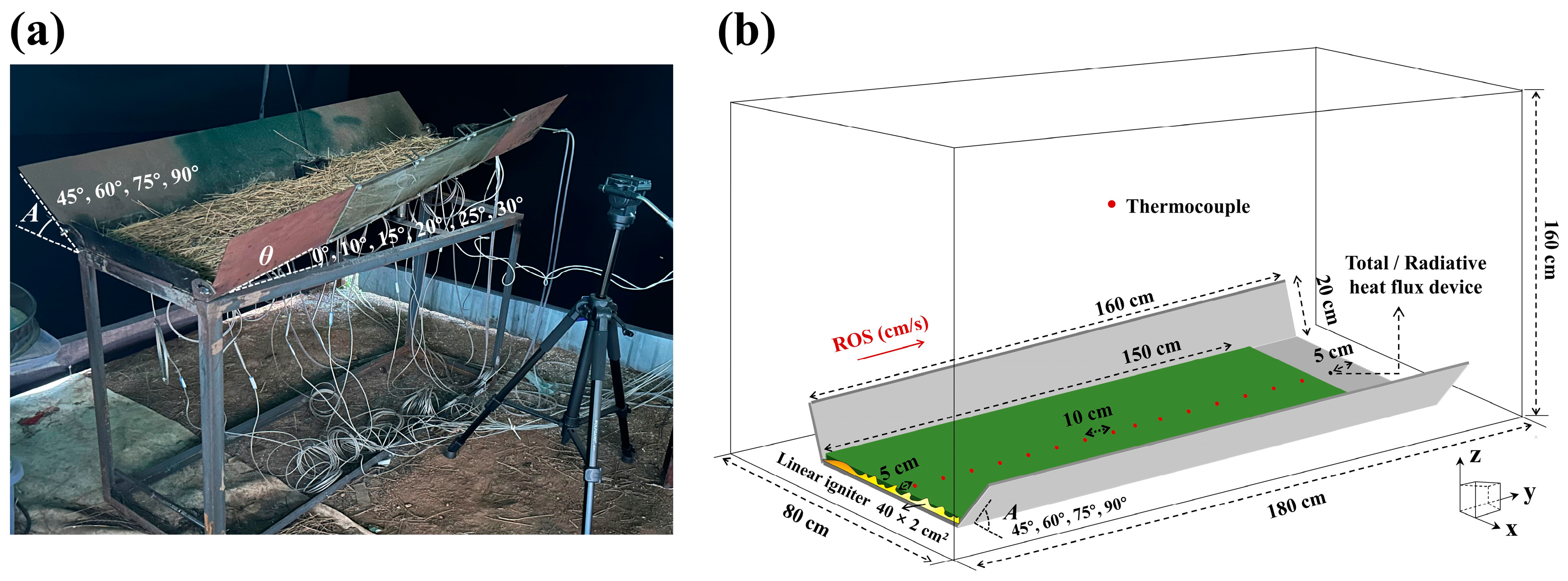
2. Experimental Methodology

A series of trench fire spread tests were carried out on a small-scale workbench, as shown in Figure 1a. This inclined trench model was 1.6 m long and 0.4 m wide, with two sidewalls of 0.2 m. To investigate the effect of slope angle (θ) and sidewall inclination (A) on trench fires, six slope angles of 0°, 10°, 15°, 20°, 25°, and 30° were used, and four sidewall inclinations of 45°, 60°, 75°, and 90° were used to generate different trench configurations. A total of 25 tests were carried out in this work. The litter pine needles from the Yimeng Mountain in northeast China were selected as fuels, and fuel moisture ranged from 5 to 10% on a dry mass basis. For each test, the fuel bed was 4 cm in depth with a uniform fuel load of 0.625 kg·m−2 to maintain an approximately constant bulk density. In the experiments, the ROS, flame morphology characteristics, and heat fluxes were recorded. The trench fires were initiated by a line ignition at the front edge of the fuel bed using a 40 cm cotton line soaked in ethanol.
The K-type thermocouples with a diameter of 2 mm were used to measure the temperature of the fuel bed surface, which were placed along the central axis of the fuel bed every 0.1 m. A radiative heat flux meter (STT-25-100-R/WF, range: 0–100 kWm−2, coefficient: 8.154 kWm−2mV−1, view angle: 150°) and a total heat flux meter (STT-25-100-R/WF, range: 0–100 kWm−2, coefficient: 8.567 kWm−2mV−1) of water-cooled type were installed 5 cm past the fuel bed end, and the top surfaces of the heat flux meters were flushed with the fuel surface. A data acquisition system (KEYSIGHT DAQ970A) was used to collect data from experiments, with a recording frequency of 0.5 s. A DV camera (SONY PXW-Z90V) was used to record the flame morphology from the side and upper front views.

3. Numerical Simulation

As a widely used numerical approach for fire simulation, FDS has been extended to simulate wildland fires in recent years [23]. This CFD method numerically solves a form of the Navier–Stokes equations appropriate for low Mach numbers and thermally driven fluids, focusing on heat transport and smoke from fires [22]. FDS provides the Lagrangian Particle Model (LPM) and Boundary Fuel Model (BFM) to achieve simulations of wildfire spread scenarios [24]. Herein, the two different methods were used to construct numerical wildfire models according to the small-scale test, and the simulation conditions were chosen to be consistent with experiments, as shown in Figure 1b.

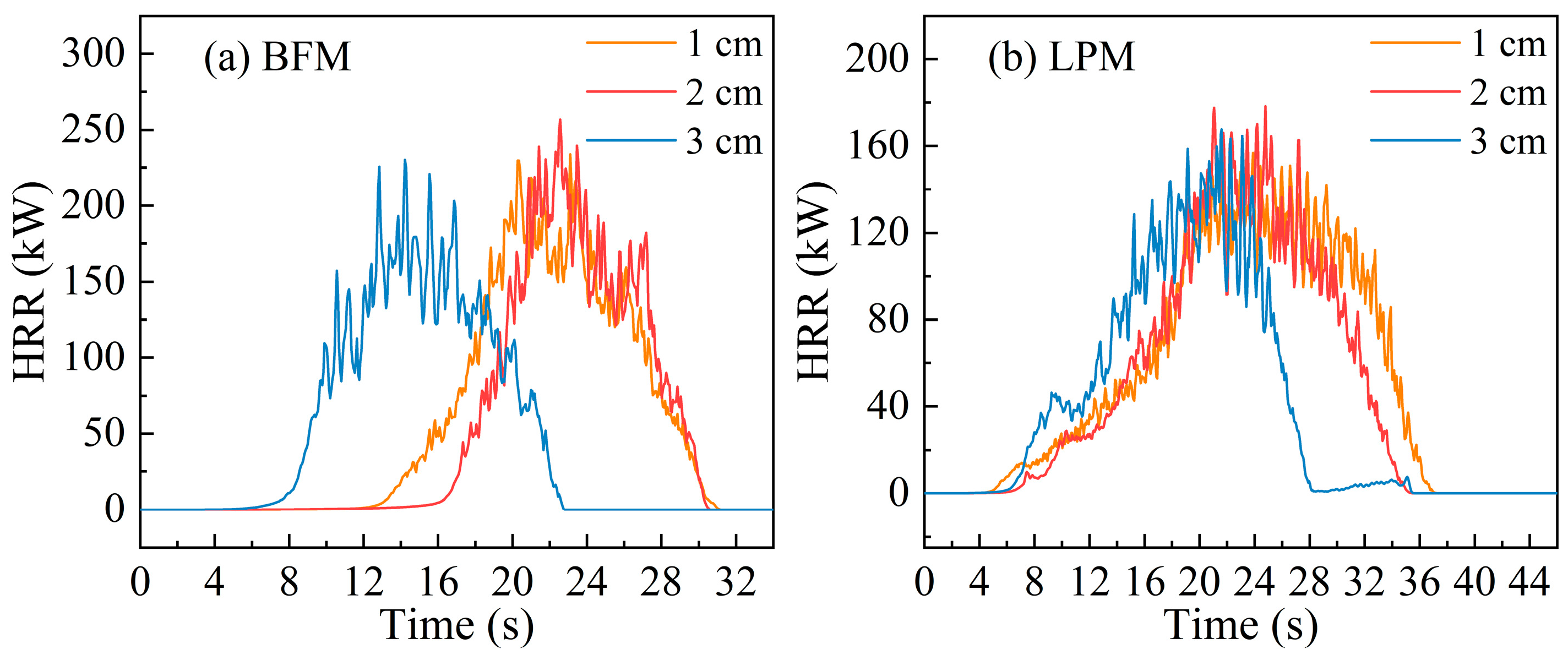
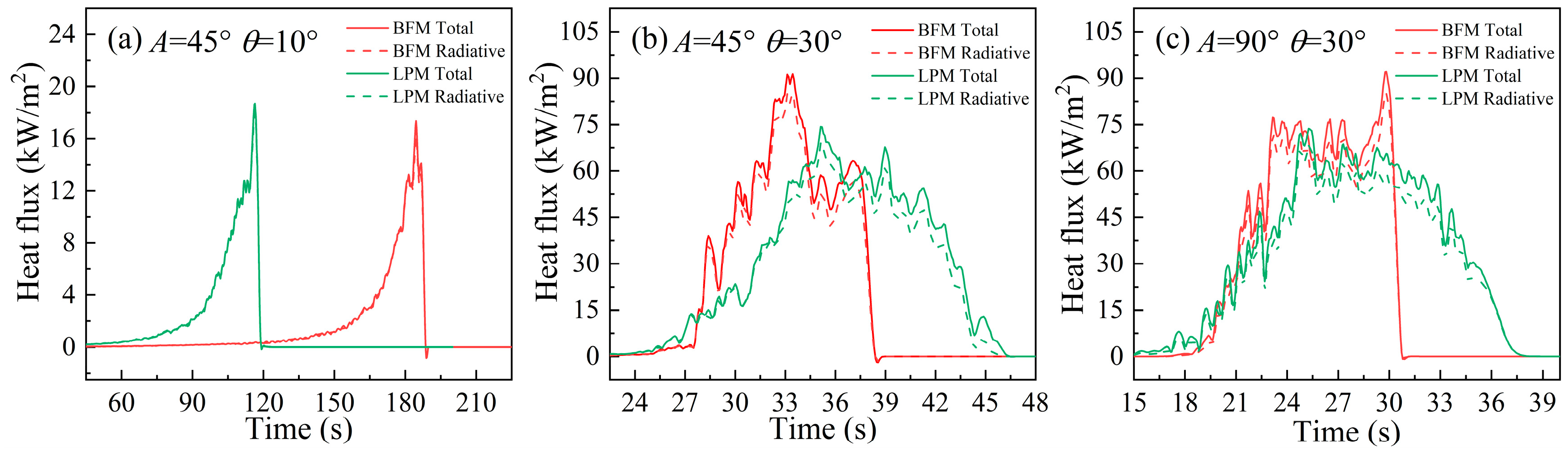
3.1. Lagrangian Particle Model and Boundary Fuel Model

Vegetation fuel in the LPM is modeled as a collection of cylindrical Lagrangian particles which can excellently represent different types of vegetation, like grass, trees, and leaves. Mell et al. [18,19] conducted fire experiments on Douglas fir and grass, and established the physics-based LPM according to the experimental results for the first time. Fiorioni et al. [22] also used the LPM method to construct several wildfire scenarios at the wildland–urban interface and assess the fire behavior characteristics. However, in BFM, fuel is represented by a porous boundary consisting of a layer of dry vegetation, moisture, and air [24], with a thickness equal to the height of the vegetation. Radiation absorbing by the vegetation layer is calculated according to a 1-D radiative transport equation and the absorption coefficient is given by:
k = C s σ β
where C s is the shape factor of vegetation (0.25 by default), σ is the surface area-to-volume ratio, and β is the packing ratio of the fuel bed. Thermal convection is imposed via a source term in the 1-D heat conduction solver:
q ˙ c , b = σ β q ˙ c
q ˙ c = h T g T s      
where h is the convective heat transfer coefficient, T g is the temperature at the center of the gas phase cell adjacent to the surface, and T s is the fuel temperature. The detailed information of the modeling is described by McGrattan [24].

3.2. Thermal Degradation Model for Vegetation

Both the LPM and BFM are based on the same thermal degradation model that includes solid-phase and gas-phase reactions, which follow the Arrhenius rate law associated with the activation energy and Boltzmann distribution [25]. The thermal degradation model involves the physicochemical and combustion kinetic properties of fuel and is typically used to predict drying, pyrolysis, and char oxidation of wet vegetation [24]. Before the simulations, the pyrolysis properties of pine needles were analyzed to characterize the solid-phase reactions, and the combustion of fuel gas was predicted by the one-step reaction in the gas phase according to McGrattan et al., as shown in Equation (4) [26]. In Table 1, the physicochemical and combustion kinetic properties are summarized. All the physics-based simulations in this work were performed using FDS 6.7.9.
C 6 H 10 O 5 + 6 O 2 + 3.76 N 2 6 C O 2 + 5 H 2 O + 22.56 N 2

3.3. Numerical Set Up

To ignite the fuel, a hot plate with a temperature of 1000 °C was set up on the fuel surface in front of the trench. The size of the numerical model was consistent with that of small-scale experiments, in which thermocouples and heat flux meters are positioned in the same position as the workbench to record temperature and heat flux changes. Sloped planes were used to construct the inclined sidewalls, and the different slope angles (θ) were achieved by adjusting components of gravity in the Y and Z directions, as given in Equation (5) below, where g = 9.81 m/s2.
g y = g sin θ ; g z = g cos θ
The cubic grid size is associated with the governing scale length of the solid phase, which is better than less than 1/3 of the fuel extinction length δ, and δ/3 is approximately 2.21 cm in this work, which can be obtained from Equation (6) [26].
δ = 4 β · σ
For the grid sensitivity tests, cubic grid sizes of 3 cm, 2 cm, and 1 cm were considered according to the governing scale length. Figure 2 shows the numerical HRR with θ = 10° and A = 45°, and it can be found that HRR curves tend to converge gradually as the grid size decreases, with little differences between the data for grid sizes of 2 cm and 1 cm. Therefore, the 2 cm grid size was chosen for this study to reduce computing costs while meeting the governing length.

4. Results and Discussion

4.1. Rate of Fire Spread

The ROS was obtained from the linear fitting of the flame front locations and the time, and the flame location was determined by the moment when the temperature measured by thermocouples reached 300 °C [7]. Figure 3a shows the nonlinear change of ROS values with varying slope for A = 90°, where the numbers in brackets represent the correlation coefficient of linear fitting. It can be seen that numerical models predict fire spread better for θ ≤ 15°, which is always less than 2.5 cm/s. At the same time, the fitted ROS show high correlations, indicating that the flame propagations are in a quasi-steady state at the lower slope. However, the ROS calculated by the numerical models is always greater than that of experiments with an increasing slope. Even for θ ≥ 20°, the ROS value in BFM is about 2.6–3.1 times that of LPM. Moreover, the correlation coefficient decreases with slope angle, indicating that fire spread may be unstable at high slopes. Figure 3b shows the data of flame front location versus time (θ ≥ 20°). It can be seen that the flame no longer advances uniformly, and there is premature burning of vegetation at the tail of the fuel bed (θ = 20° for BFM and θ = 25° for LPM). It is inferred that the flame morphology is influenced by air entrainment, thus affecting the fire spreading process.
There is a critical slope angle of 15°, at which point ROS begins to grow from 0.44 m/s to 1.13 m/s. The critical slope angle in the numerical simulation is also about 15°; however, the numerical model predicts a larger acceleration. The discrepancy of experiments and numerical simulation is discussed in the following parts. In Monroy’s [8] upslope fire tests, the critical slope angle was also found to be around 16°, and in Xie’s [7] tests, the ROS started to rise sharply at around 25° when the aspect ratio of the trench was 0.4. It can be inferred that the acceleration in fire propagation associated with the varying flame behavior in trench terrain will occur at a slope angle of 15–25°.

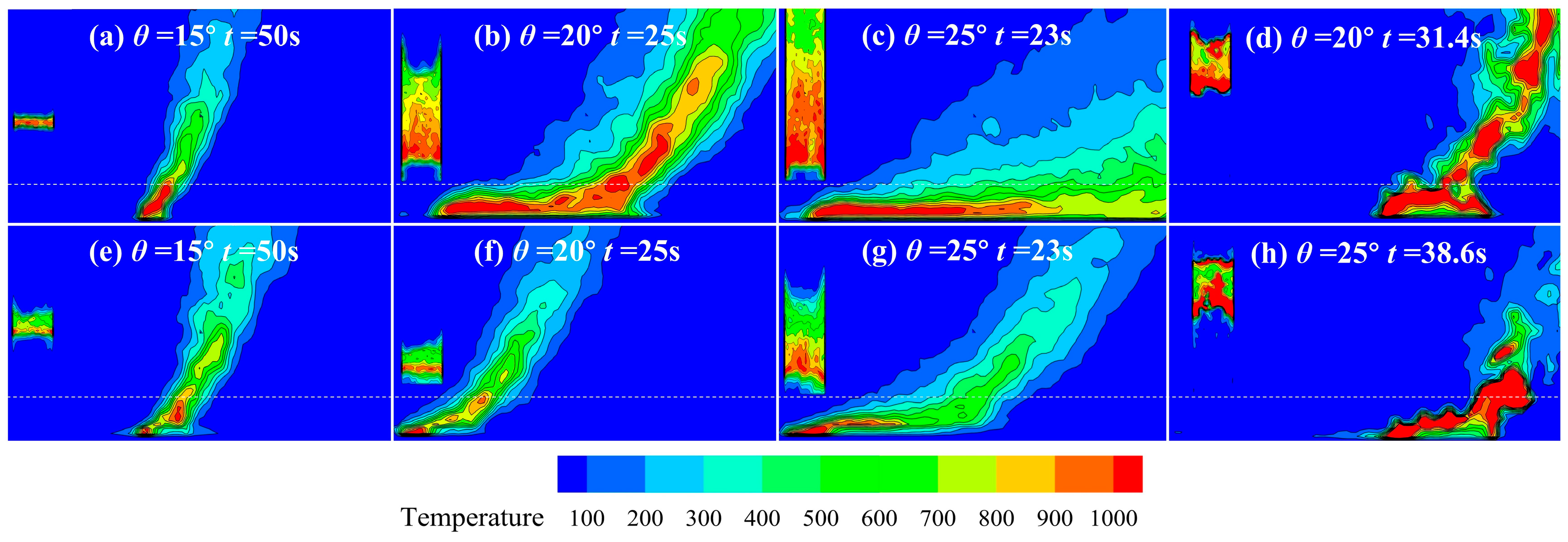
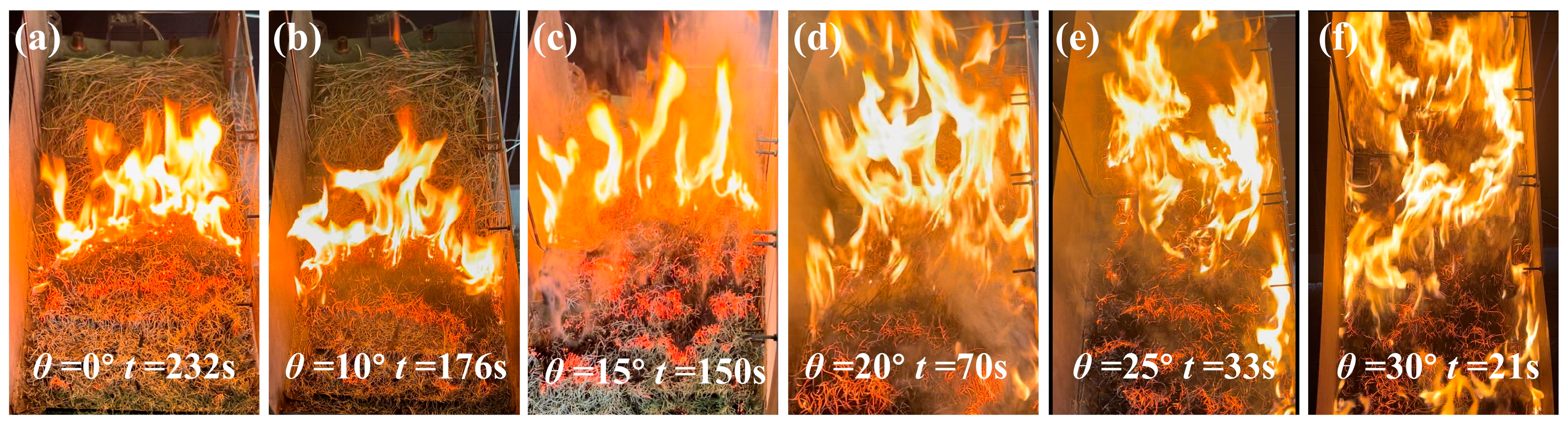
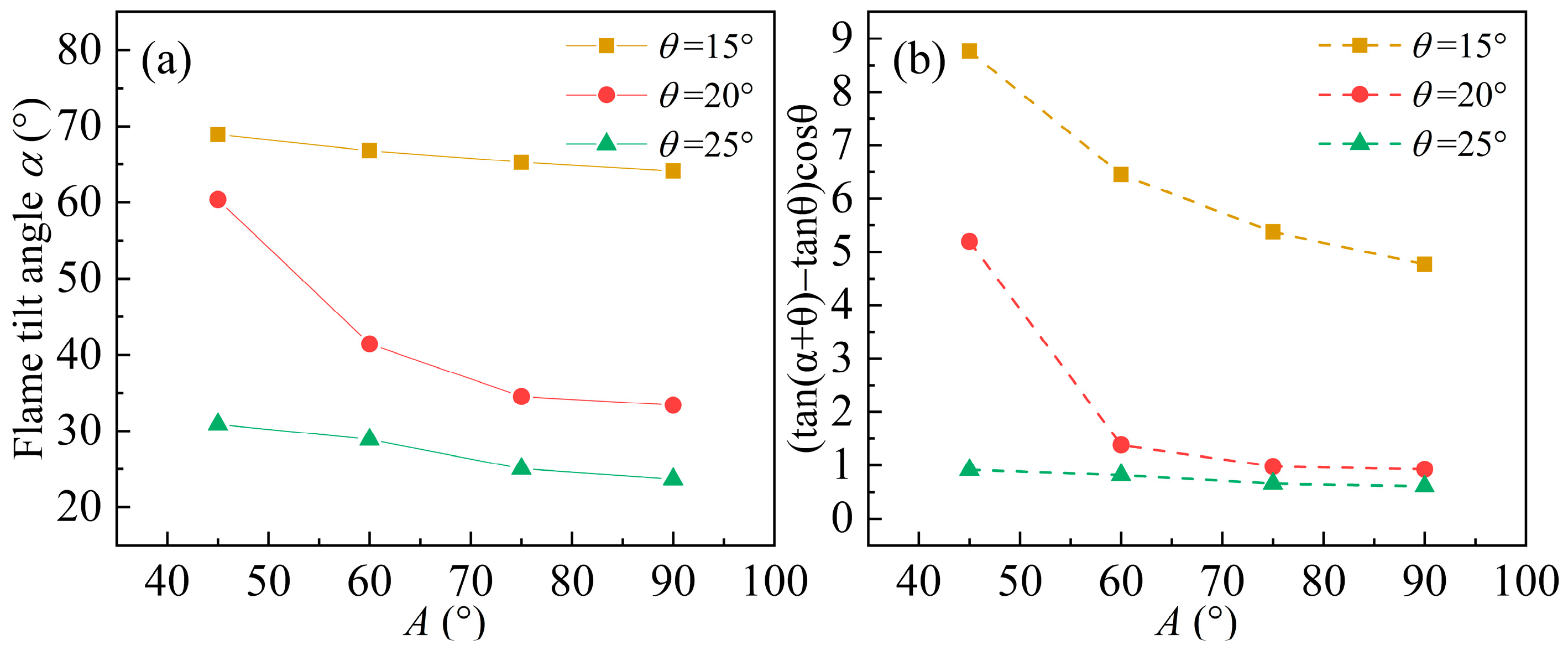
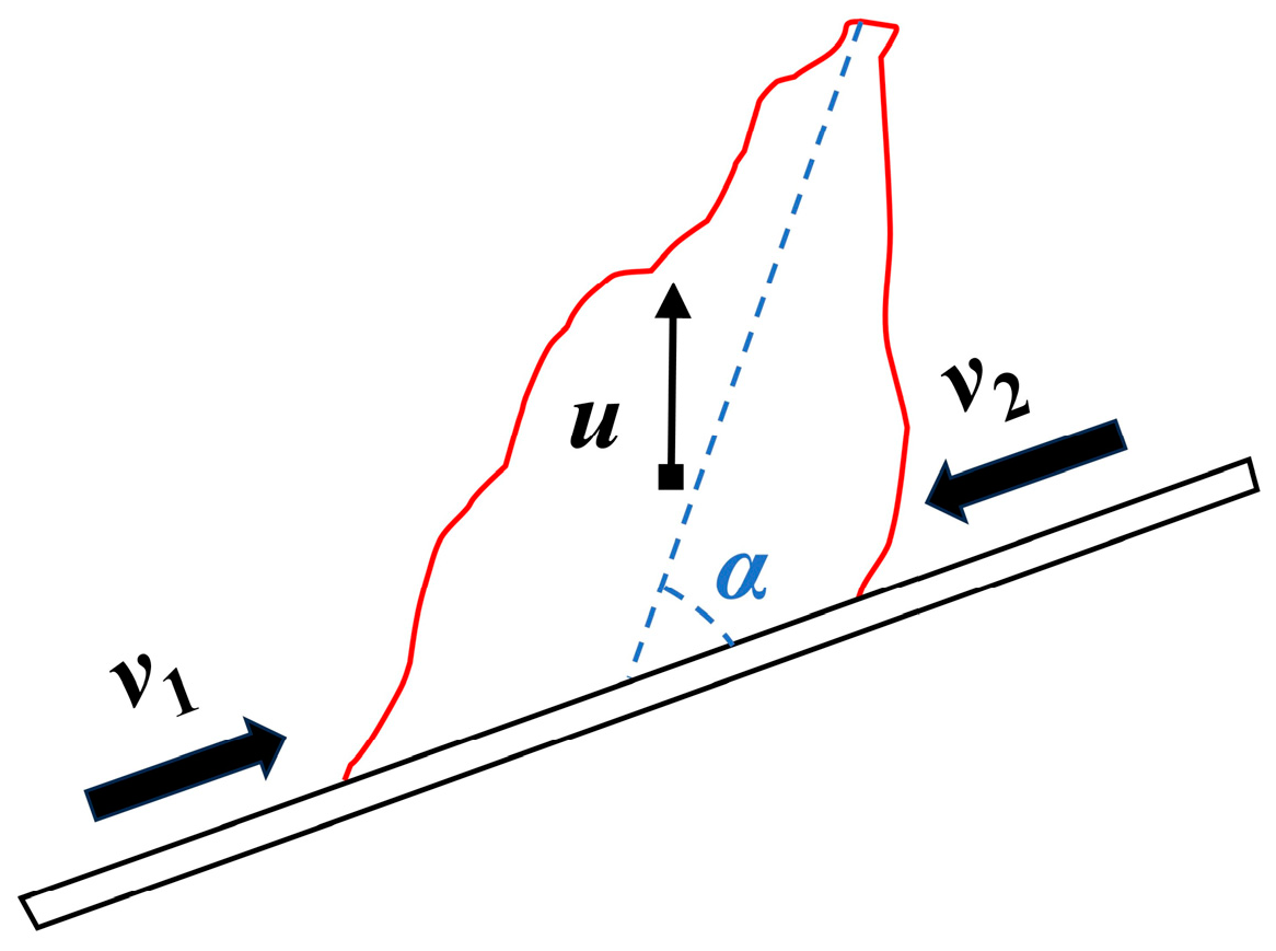
4.2. Flame Morphology Characteristics

The temperature contours of the flame longitudinal section were obtained through the two numerical approaches of BFM and LPM with A = 90°, as shown in Figure 4, and the flame progressions are presented on the left of each figure. In Figure 4a–c,e–g, it can be seen that the attachment of the flame lower than the sidewall is extended as the θ increases, and the flame higher than the sidewall is sharply inclined along the slope. For θ = 15°, the flame is slightly adhered, and it remains almost vertical due to the flame buoyancy. Moreover, the fuel preheating area in Figure 4e is larger than that in Figure 4a, implying that there is a development of fire spread in LPM, which is consistent with the increasing ROS in Figure 3a. When BFM predicts fire propagation for θ > 15°, the flame attachment and the longitudinal section area are sharply expanded compared with LPM, indicating that the rapid acceleration in ROS is significantly influenced by the flame adhesion and flame volume combined with Figure 3a. As the fire spreads to the end of the fuel bed (where the location of the last thermocouple is), flame morphologies are depicted in Figure 4d,h. As shown, the flame adhesion and the flame front are no longer regular and slender, which suggests that air entrainment around the opening is causing flame morphology to shift from regular to chaotic. The phenomenon of premature fuel burning in Figure 3b also supports the view, and it might be extrapolated that there is an unpredictability for wildfires at the end of the trench, which could lead to more catastrophes for firefighting and humans.
Figure 5 presents the flame progressions recorded in the experiments under trenches with A = 90°. For slopes between 0° and 15°, the fire line maintains the U-shape and steadily advances, as shown in Figure 5a–c. The steady states can also be confirmed by the correlation coefficient of linear fitting that is greater than 0.99 in Figure 3a. For θ = 20°, the burning becomes more intense with the fire line changing from a U to a V shape. As the slope is greater than 20°, the fire front is no longer linear, and the flame propagates quickly, covering the entire fuel bed in a short time. This irregular propagation is more remarkable when θ = 30°. According to the above, this suggests that there is a critical slope angle between 15 and 25° which induces the acceleration of flame progression from a steady state.
Flame photos taken from experiments were converted into grayscale images with OpenCV, and the flame inclination is the angle between the flame top and the fuel bed, which was obtained by ImageJ. The flame inclination angle α is of great significance to the heat transfer at the fire front, resulting in the changing ROS. Following that, the effect of θ and A on flame inclination angle was mainly analyzed. Figure 6 represents the flame morphologies for θ = 10–20° with A = 45–90°. It can be found that the flame front keeps almost vertical when θ = 15° and there is a slight attachment of the flame as θ increases. However, intense flame behavior occurred, characterized by the flame length increasing and full flame attachment when θ = 25°. In Figure 7a, the flame inclination angles (α) for different A and θ are presented. As shown, α remains at 65–70° for θ =15°, while there is a remarkable decrease under high-slope cases. In addition, θ = 20° is confirmed to be a critical slope angle when flame morphology is most influenced by sidewalls. Comparatively, for numerical results, the prediction of critical slope is also around θ = 20°, as shown in Figure 4, which is consistent with the experimental findings. Furthermore, when the slope is 25°, α is between 31° and 25° for various A, and the low flame tilt angles α with little variations infer that there is full flame attachment, which is also illustrated by the flame morphology in Figure 6.
Note that for the same slope angle, the reduction of α is approximately 40° when A inclines from 45° to 90°. It could be inferred that more air entrainments occurred on the fire front to obtain sufficient air for burning, while the air entrainments on the left and right sides are restricted by the inclined sidewall, which causes the flame to incline significantly. Moreover, the larger the sidewall inclination, the narrower the trench space. The gas produced during burning accumulates inside the trench, and the buoyancy and expansion force of the gas at a high temperature further drive the flame to adhere to the slope, as reported by Chen et al. [14].
In flame propagation, the air flow influencing fire behavior includes the vertical flow with a rate of u caused by buoyancy and the air entrainment behind and in front of the flame with rates of v1 and v2, as presented in Figure 8. For no-slope cases, the air entrainment on both sides of the flame is equal, and the buoyancy makes the flame almost vertical. As the slope angle rises, the component of buoyancy along the slope restricts air entrainment in the fire front, and the pressure differential generated by the v = v 1 v 2 leads the flame to incline until adhesion. In order to further investigate the rule of air flow around the flame, Equation (7) was used to quantify the gas flow velocity in vertical and horizontal components, and Equation (7) can also be translated into Equation (8).
tan α + θ ~ u + v sin θ v cos θ
u v ~ tan α + θ tan θ cos θ
The data of tan α + θ tan θ cos θ can be used to quantify the relative fluctuation between the vertical gas velocity u induced by buoyancy and the v along the slope. In Figure 6b, it is found that tan α + θ tan θ cos θ decreases with rising slope angle θ for the same A cases, indicating that buoyancy plays a more significant role than the pressure difference generated by v at lower slopes. For θ = 15 and θ = 20°, the sidewall inclination A increases from 45° to 60°, resulting in a sharp reduction in the value of tan α + θ tan θ cos θ . It is suggested that the cause of the flame inclining toward the slope is the enhancement in the pressure difference on both sides of the flame. Furthermore, tan α + θ tan θ cos θ < 1 occurs for θ = 25°, and it can be inferred that when the pressure difference is greater than the vertical buoyancy, the flame inclines remarkably and is in a state of complete attachment, which is illustrated by Figure 6.

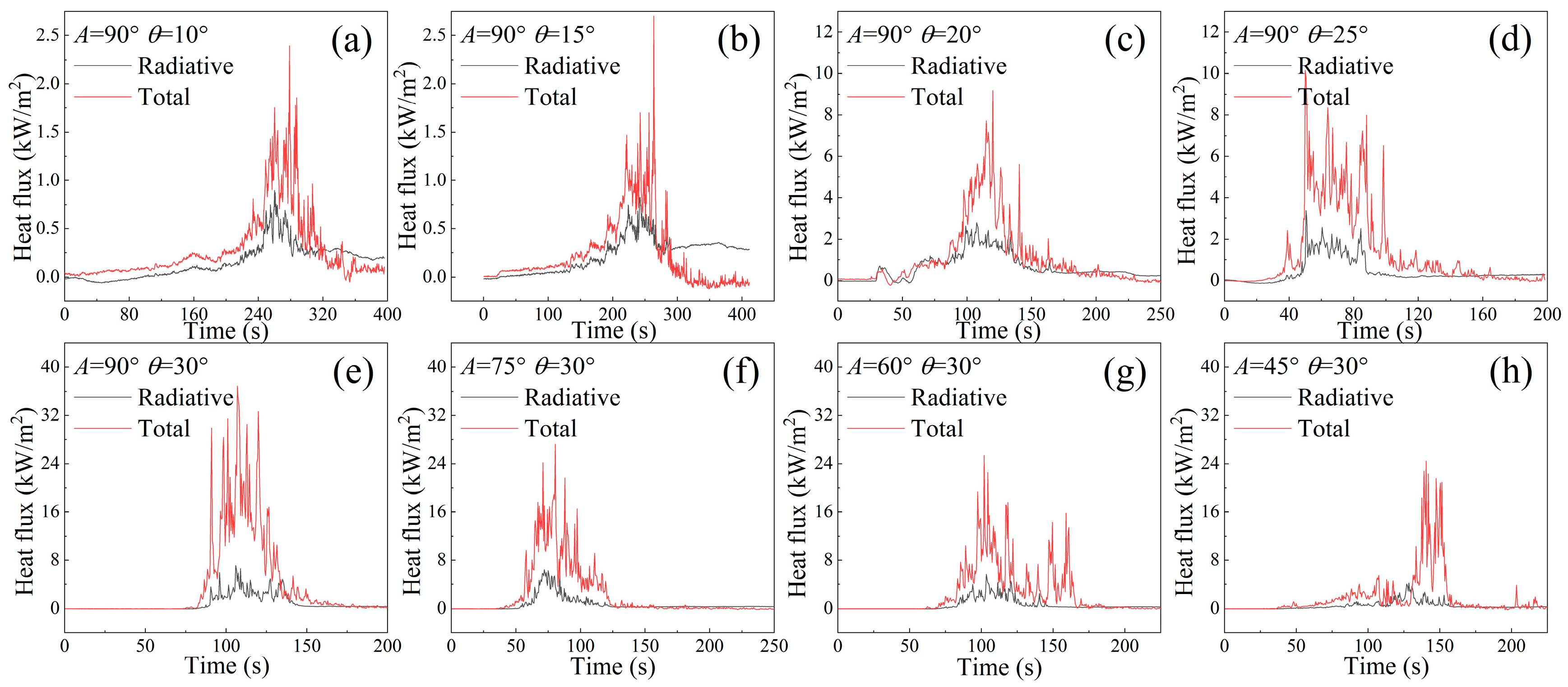
4.3. Fuel Preheating Mechanism

In order to explore the fuel preheating mechanism, the total/radiant heat flux meters were positioned at the end of the trench to measure the heat flux of the fuel surface. Figure 9 and Figure 10 present the heat flux data obtained from small-scale experiments and numerical simulations.
As shown in Figure 9a,b, the magnitude of total and radiative heat flux is equivalent, meaning radiation is the dominant heating mechanism in trench fires for θ = 10–15°. During this period, the heat transfer from the flame to the fuel is less than 2.5 kW/m2, implying a low rate of fire propagation, which is consistent with the ROS change shown in Figure 3a. When θ = 20°, the total heat flux is much higher than the values for θ = 15°; however, the radiative heat flux is slightly improved. This indicates the marked convective heating of the fire front. When θ ≥ 20°, there is only 25–40% total heat flux coming from radiation, suggesting convective heat transfer starts to be more important and becomes the main heating mechanism, which may be associated with the convective heating form of short-distance heating caused by the turbulent diffusion of the flame and longer-distance heating caused by the contact of the hot gas with the fuel surface [7]. For A = 90° with θ = 30°, ROS in the experiments increases to 2.5 times the value for θ = 20°, which is mainly caused by a great improvement in convective heating, as illustrated by Figure 9c,e. Under high-slope (θ = 30°) cases as presented in Figure 9e–h, raising A results in a remarkable enhancement of convective heat flux. Above all, it was confirmed that the slope θ and the sidewall inclination A affect fire behavior primarily by enhancing convective heat transfer during the fuel heating.
The heat fluxes predicted by BFM and LPM are presented in Figure 10. As shown, in the case of θ = 10°, the heat flux peak obtained from LPM is slightly higher than that for BFM. The higher heat flux enhances the fuel preheating, resulting in the differences in ROS in Figure 3a. Also, the data reveal that the fuel preheating is mainly derived from radiative heat transfer for θ = 10°, with only minor convections, which is similar to the experimental findings. However, when θ = 30°, the heat flux in BFM is remarkably greater than that for LPM, resulting in a shorter combustion period in BFM. The causes of the data discrepancy between BFM and LPM are as follows: BFM and LPM used particle and boundary methods to construct vegetation, respectively, and different calculation methods of the two models would lead to discrepancies in calculation results. For example, vegetation represented by Lagrangian particles occupies two layers of grid cells, while the fuel in BFM is realized by a single layer of vent surface, which causes the difference in the calculation of the 1-D radiative transport equation and convective heat equation, as stated by McGrattan [24]. Moreover, it can be seen from Figure 9 and Figure 10 that the numerical models overestimate the heat flux because there is heat dissipation between the flame and the experimental platform, as well as disturbance of the ambient wind, leading to reduction of heat flux. The lower heat fluxes result in a slower ROS, which is consistent with Figure 3. If the heat dissipation between the flame and the ambient temperature is considered, the heat flux will decrease.

5. Conclusions

Herein, the effect of slope (θ) and sidewall inclination (A) on fire behavior in trench terrain was investigated in detail. Numerical simulations based on FDS and small-scale tests were performed with a uniform fuel bed (fixed fuel load, fuel packing ratio, and fuel height). The work offers great advantage in understanding the fire behavior characteristics in various trenches over a uniform fuel bed. The experimental and numerical results indicate that the ROS accelerates with θ increasing, and BFM and LPM could predict the ROS at low slopes well (θ ≤ 15°). In high-slope cases (θ ≥ 20°) and near the end of the trench terrain, turbulent flame propagation and attachment may cause the trench fire to become out of control, thus posing a serious threat to firefighting. The variation in flame morphology demonstrates the larger pressure difference between the two sides of the flame than the buoyancy, resulting in sharp flame inclination and full attachment. In addition, increasing A and θ significantly enhances convective heating of the fire front. For lower slopes (θ = 10–15°) with steady fire propagation, radiation is the primary heating transfer mechanism, while convective heating plays a more important role in fuel preheating as the slope increases. Furthermore, for higher slopes in trench fires (θ = 20–30°), it was found that convective heating becomes the dominant heating mechanism in trench fires.
This work explores the fire propagation behavior in diverse trench topographies over a uniform fuel bed, which provides a reference for trench fire control in actual scenarios. However, the features of fuel beds in actual field fires are quite complex, and the fire line intensity and burning behavior of large-scale fires could be more intense. In view of these, larger-scale experiments and numerical simulations are required to further investigate flame propagation in heterogeneous fuel beds, complex trench scales, and climatic environments.

Author Contributions

Conceptualization, Y.W. and R.H.; methodology, Y.W. and R.H.; experiment, Y.W.; numerical simulation, Y.W.; validation, Y.W. and R.H.; formal analysis, Y.W.; investigation, Y.W.; writing—original draft preparation, Y.W.; writing—review and editing, Y.W.; visualization, Y.W.; supervision, R.H.; funding acquisition, R.H. All authors have read and agreed to the published version of the manuscript.

Funding

This work was supported by the Fundamental Research Funds for the Central Universities of Central South University (2023ZZTS0803) and the High Performance Computing Center of Central South University. This work was also supported by the Industrial Internet Innovation and Development Project (ZTZB-23-990-021) and Ningxia Autonomous Region Key Research and Development Plan (2022BEE02001).

Institutional Review Board Statement

Not applicable.

Informed Consent Statement

Not applicable.

Data Availability Statement

No new data were created or analyzed in this study. Data sharing is not applicable to this article.

Conflicts of Interest

The authors declare no conflict of interest.

References

  1. Liu, N.; Lei, J.; Gao, W.; Chen, H.; Xie, X. Combustion Dynamics of Large-Scale Wildfires. Proc. Combust. Inst. 2021, 38, 157–198. [Google Scholar] [CrossRef]
  2. Bufacchi, P.; Krieger, G.C.; Mell, W.; Alvarado, E.; Santos, J.C.; Carvalho, J.A. Numerical Simulation of Surface Forest Fire in Brazilian Amazon. Fire Saf. J. 2016, 79, 44–56. [Google Scholar] [CrossRef]
  3. Frangieh, N.; Accary, G.; Rossi, J.-L.; Morvan, D.; Meradji, S.; Marcelli, T.; Chatelon, F.-J. Fuelbreak Effectiveness against Wind-Driven and Plume-Dominated Fires: A 3D Numerical Study. Fire Saf. J. 2021, 124, 103383. [Google Scholar] [CrossRef]
  4. Sullivan, A.L. Wildland Surface Fire Spread Modelling, 1990–2007. 1: Physical and Quasi-Physical Models. Int. J. Wildland Fire 2009, 18, 349. [Google Scholar] [CrossRef]
  5. Sullivan, A.L. Wildland Surface Fire Spread Modelling, 1990–2007. 2: Empirical and Quasi-Empirical Models. Int. J. Wildland Fire 2009, 18, 369. [Google Scholar] [CrossRef]
  6. Li, H.; Liu, N.; Xie, X.; Zhang, L.; Yuan, X.; He, Q.; Viegas, D.X. Effect of Fuel Bed Width on Upslope Fire Spread: An Experimental Study. Fire Technol. 2021, 57, 1063–1076. [Google Scholar] [CrossRef]
  7. Xie, X.; Liu, N.; Lei, J.; Shan, Y.; Zhang, L.; Chen, H.; Yuan, X.; Li, H. Upslope Fire Spread over a Pine Needle Fuel Bed in a Trench Associated with Eruptive Fire. Proc. Combust. Inst. 2017, 36, 3037–3044. [Google Scholar] [CrossRef]
  8. Sánchez-Monroy, X.; Mell, W.; Torres-Arenas, J.; Butler, B.W. Fire Spread Upslope: Numerical Simulation of Laboratory Experiments. Fire Saf. J. 2019, 108, 102844. [Google Scholar] [CrossRef]
  9. Viegas, D.X. Parametric Study of an Eruptive Fire Behaviour Model. Int. J. Wildland Fire 2006, 15, 169. [Google Scholar] [CrossRef]
  10. Viegas, D.X.; Simeoni, A. Eruptive Behaviour of Forest Fires. Fire Technol. 2011, 47, 303–320. [Google Scholar] [CrossRef]
  11. Viegas, D.X.; Rodrigues, A.; Abouali, A.; Almeida, M.; Raposo, J. Fire Downwind a Flat Surface Entering a Canyon by Lateral Spread. Fire Saf. J. 2021, 122, 103349. [Google Scholar] [CrossRef]
  12. Dold, J. Flow Attachment in Eruptive Fire Growth. In Proceedings of the VI International Conference on Forest Fire Research, Coimbra, Portugal, 18–19 November 2010. [Google Scholar]
  13. Dupuy, J.-L.; Marechal, J.; Portier, D.; Valette, J.-C. The Effects of Slope and Fuel Bed Width on Laboratory Fire Behaviour. Int. J. Wildland Fire 2011, 20, 272–288. [Google Scholar] [CrossRef]
  14. Chen, C.; Nie, Y.; Zhang, Y.; Lei, P.; Jiao, W.; Wang, X. Experimental Study on Flame Spread over Poplar Plywood in Inclined Trench: Phenomenon of Flame Injection. J. Therm. Anal. Calorim. 2021, 146, 253–263. [Google Scholar] [CrossRef]
  15. Xu, T.; Zhao, D.; Tao, H.; Lei, P. Extended CFD Models for Numerical Simulation of Tunnel Fire under Natural Ventilation: Comparative Analysis and Experimental Verification. Case Stud. Therm. Eng. 2022, 31, 101815. [Google Scholar] [CrossRef]
  16. Sullivan, A.L. Wildland Surface Fire Spread Modelling, 1990–2007. 3: Simulation and Mathematical Analogue Models. Int. J. Wildland Fire 2009, 18, 387. [Google Scholar] [CrossRef]
  17. Woodburn, P.J.; Drysdale, D.D. Fires in Inclined Trenches: The Dependence of the Critical Angle on the Trench and Burner Geometry. Fire Saf. J. 1998, 31, 143–164. [Google Scholar] [CrossRef]
  18. Mell, W.; Maranghides, A.; McDermott, R.; Manzello, S.L. Numerical Simulation and Experiments of Burning Douglas Fir Trees. Combust. Flame 2009, 156, 2023–2041. [Google Scholar] [CrossRef]
  19. Mell, W.; Jenkins, M.A.; Gould, J.; Cheney, P. A Physics-Based Approach to Modelling Grassland Fires. Int. J. Wildland Fire 2007, 16, 1–22. [Google Scholar] [CrossRef]
  20. Innocent, J.; Sutherland, D.; Khan, N.; Moinuddin, K. Physics-Based Simulations of Grassfire Propagation on Sloped Terrain at Field Scale: Motivations, Model Reliability, Rate of Spread and Fire Intensity. Int. J. Wildland Fire 2023, 32, 496–512. [Google Scholar] [CrossRef]
  21. Innocent, J.; Sutherland, D.; Khan, N.; Moinuddin, K. Physics-Based Simulations of Grassfire Propagation on Sloped Terrain at Field Scale: Flame Dynamics, Mode of Fire Propagation and Heat Fluxes. Int. J. Wildland Fire 2023, 32, 513–530. [Google Scholar] [CrossRef]
  22. Fiorini, C.; Craveiro, H.D.; Santiago, A.; Laím, L.; Simões Da Silva, L. Parametric Evaluation of Heat Transfer Mechanisms in a WUI Fire Scenario. Int. J. Wildland Fire 2023, 32, 1600–1618. [Google Scholar] [CrossRef]
  23. Valero, M.M.; Jofre, L.; Torres, R. Multifidelity Prediction in Wildfire Spread Simulation: Modeling, Uncertainty Quantification and Sensitivity Analysis. Environ. Model. Softw. 2021, 141, 105050. [Google Scholar] [CrossRef]
  24. McGrattan, K.; Hostikka, S.; Floyd, J.; McDermott, R.; Vanella, M.; Mueller, E. Sixth Edition Fire Dynamics Simulator User’s Guide (FDS); National Institute of Standards and Technology: Gaithersburg, MD, USA, 2023; Volume 6.
  25. Meerpoel-Pietri, K.; Tihay-Felicelli, V.; Graziani, A.; Santoni, P.-A.; Morandini, F.; Perez-Ramirez, Y.; Bosseur, F.; Barboni, T.; Sánchez-Monroy, X.; Mell, W. Modeling with WFDS Combustion Dynamics of Ornamental Vegetation Structures at WUI: Focus on the Burning of a Hedge at Laboratory Scale. Combust. Sci. Technol. 2022, 195, 3181–3211. [Google Scholar] [CrossRef]
  26. Perez-Ramirez, Y.; Mell, W.E.; Santoni, P.A.; Tramoni, J.B.; Bosseur, F. Examination of WFDS in Modeling Spreading Fires in a Furniture Calorimeter. Fire Technol. 2017, 53, 1795–1832. [Google Scholar] [CrossRef]
Figure 1. (a) Experimental workbench; (b) numerical model of sloped trench fires.
Fire 06 00469 g001
Figure 2. Numerical HRR curves for the 3 cm, 2 cm, and 1 cm grid cell sizes (θ = 10°, A = 45°).
Fire 06 00469 g002
Figure 3. (a) Variations of ROS value with increasing slope (A = 90°); (b) changes in the fire front locations over time (θ ≥ 20°).
Fire 06 00469 g003
Figure 4. Temperature contours of fuel bed surface and flame longitudinal section in numerical simulations (A = 90°), shown in (ad) for BFM and (eh) for LPM, with the white line representing the side wall edge.
Fire 06 00469 g004
Figure 5. The typical photos of fire propagation modes with various slopes recorded from the front of the fuel bed.
Fire 06 00469 g005
Figure 6. Flame longitudinal morphology captured in small-scale experiments.
Fire 06 00469 g006
Figure 7. (a) Variations of flame tilt angle with A and θ; (b) variations of tan α + θ tan θ cos θ with A and θ.
Fire 06 00469 g007
Figure 8. Schematic of air entrainment on both sides of the flame.
Fire 06 00469 g008
Figure 9. Measured total heat flux and radiative heat flux in experiments.
Fire 06 00469 g009
Figure 10. Measured total heat flux and radiative heat flux in BFM and LPM.
Fire 06 00469 g010
Table 1. Physicochemical and combustion kinetic properties used for simulations.
ParameterValueParameterValue
Radiative fraction χ r 0.27 [8]Moisture fraction M0.1
Soot yield χ s (kg/kg)0.02 [22]Char fraction χ c h a r 0.2 [24]
Drag coefficient Cd2.8 [24]Density ρ (kg/m3) 500 [24]
Shape factor Cs0.25 [24]Conductivity c (W/(m·K))0.1 [24]
Fuel height h (m)0.04Specific heat (kJ/(kg·K))1.0 [24]
Fuel packing ratio β0.03Reference temperature (°C)300 [24]
Fuel load ω (kg/m2)0.625Heat of pyrolysis Δ h p y r   ( k J · k g 1 ) 711 [8]
Ignition area s (m2)0.4 × 0.02Fuel gas C6H10O5 [24]
Ignition temperature (°C)1000Combustion heat of fuel gas Q ( k J · k g 1 )17,260 [24]
Environment temperature Tg (°C)20Surface area-to-volume ratio σ (m−1)2010
Disclaimer/Publisher’s Note: The statements, opinions and data contained in all publications are solely those of the individual author(s) and contributor(s) and not of MDPI and/or the editor(s). MDPI and/or the editor(s) disclaim responsibility for any injury to people or property resulting from any ideas, methods, instructions or products referred to in the content.

