Abstract
Theoretical studies have indicated that borophene is a promising two-dimensional material characterized by remarkable chemical, mechanical, and electrical properties. Nonetheless, its practical applications in areas such as catalysis and gas sensing are hindered by the limited density of reactive sites in its pristine form. To address this limitation, the present study explores the controlled fluorination of borophene nanoflakes as a strategy to modify their surface chemistry and enhance the availability of active sites. Furthermore, it is anticipated that surface fluorination will improve hydrophobicity, which is crucial for reducing humidity-related interference in sensing applications. In this study, we report the successful functionalization of borophene nanoflakes with fluorine using a plasma arc discharge technique for the first time. Borophene nanolayers were synthesized via a sonochemical-assisted exfoliation method, yielding nanosheets with an average lateral dimension of approximately 100 nm. The fluorinated samples were characterized using X-ray photoelectron spectroscopy (XPS), X-ray diffraction (XRD), and high-resolution transmission electron microscopy (HRTEM). A systematic investigation of plasma exposure durations demonstrated that fluorine was effectively introduced as a dopant while maintaining the crystallinity of the borophene lattice.
1. Introduction
Over the past two decades, two-dimensional (2D) nanomaterials have garnered significant research interest due to their unique properties and a wide range of potential applications. These materials are characterized by their atomic-scale thickness, large surface area, and exceptional physical and chemical properties, which differ markedly from those of their bulk counterparts due to quantum confinement effects and high surface-to-volume ratios [1]. Notable examples of 2D materials include graphene [2], transition metal dichalcogenides (TMDs) [3], phosphorene [4], and hexagonal boron nitride (h–BN) [5], all of which have been extensively studied for various applications. In this context, 2D nanomaterials have demonstrated utility in numerous fields, including catalysis [6], advanced electronics [7], energy storage [8], and electrochemistry [9]. Additionally, the functional versatility of 2D nanomaterials is complemented by their potential for scalable and cost-effective production, facilitated by a variety of top-down and bottom-up synthesis methods [10].
In recent years, nano-sized boron sheets, referred to as borophene in analogy to graphene, have attracted considerable attention due to their exceptional properties. The unique electronic structure of borophene is characterized by high carrier mobility and excellent thermal conductivity [11], which suggests significant potential for applications in sensors and catalysis. Theoretical studies have predicted that borophene may exceed graphene in terms of intrinsic carrier mobility at room temperature [12], higher Fermi velocity [13], and greater Young’s modulus [14], among other attributes. Furthermore, borophene exhibits remarkable properties related to flexibility, strength, and elasticity [15], positioning it as an ideal candidate for flexible electronic applications. The complexity of the boron bonding also results in significant polymorphism [16], allowing for various crystal structure arrangements. The most extensively studied phases of borophene include B12, X3, honeycomb structures, and 2–Pmmm [17]. This polymorphic structure highlights the high potential of borophene to have its properties tailored for specific applications. Unlike graphene, the electron-deficient character of borophene enables tunable electronic properties, ranging from metallic behavior to semiconducting phases, under external stimuli such as strain, electric fields, or functionalization [18]. This versatility enhances its applicability across various domains.
However, pristine nanomaterials, including borophene, often exhibit limited applicability in real-world settings. For instance, in gas sensing applications, unmodified borophene is expected to demonstrate poor specificity in interacting with gas molecules. Consequently, surface engineering is frequently required to enhance performance for targeted applications. Among the various techniques available for tailoring the surface chemistry of nanomaterials, elemental functionalization has emerged as a versatile approach for fine-tuning electronic, chemical, and physical properties [19,20]. Plasma techniques have proven particularly advantageous for achieving elemental functionalization due to their solvent-free nature, minimization of waste generation, fast processing, and the possibility to achieve non-destructive functionalization [21]. Furthermore, plasma processes allow for precise control over functionalizing parameters, such as spatial distribution and concentration, which are critical for maintaining the structural integrity of the nanomaterial while achieving the desired modifications [22].
Among the different functionalizing elements, fluorine remains relatively unexplored compared to noble metals or rare earth elements. However, fluorine possesses significant potential for enhancing the chemical and electronic properties of materials. Due to its high electronegativity and small atomic radius, fluorine tends to form strong covalent bonds with surfaces, stabilizing materials and imparting unique functionalities [23]. In carbon-based systems, such as graphene and carbon nanotubes, fluorination has demonstrated notable benefits. For example, C. Struzzi et al. performed a fluorination of carbon nanotubes (CNTs) to minimize the interference of ambient moisture during ambient monitoring of pollutant gases [24]. The addition of fluorine atoms significantly increased the hydrophobicity, which is particularly valuable in sensing applications, where humidity can compromise the reliable detection of atmospheric pollutants.
In this context, the addition of fluorine to borophene, given its exceptional properties, may facilitate the development of advanced 2D nanomaterials. To date, very few theoretical works have reported the fluorination of borophene, despite its promising implications. Theoretical investigations suggest that fluorination could similarly enhance borophene’s structural integrity, enabling tunable electronic and optical properties. For instance, computational models predict that fluorinated borophene exhibits an increased work function and anisotropic thermal conductivity, properties particularly advantageous for electronics [23,25]. Despite these promising theoretical predictions, the fluorination of borophene remains largely unaddressed. Recently, M.M. Morey et al. reported the first synthesis of fluoroborophene [26], a 2D nanomaterial characterized by significant fluorine content (ranging from 12 to 35%), achieved through a solvothermal method using KF as a reagent. In contrast, this study presents a novel approach for moderate borophene fluorination (i.e., functionalization) employing a plasma-assisted method to achieve controlled functionalization. By modulating plasma parameters such as functionalization time, this study aims to characterize the surface chemistry changes induced by X-ray photoelectron spectroscopy (XPS). However, careful consideration is required in the fluorine functionalization process, as exceeding a certain threshold may disrupt the borophene lattice, resulting in undesirable properties. Therefore, this seeks to establish an effective fluorine functionalizing strategy that preserves the crystallinity of borophene.
2. Experimental Section
2.1. Borophene Synthesis
Commercially sourced boron powder with an average particle size of 2 µm and isopropyl alcohol (IPA) were used. The sonochemical synthesis method followed our previous work [27]. Briefly, a suspension was prepared by adding boron powder to an IPA solution at a concentration of 1 mg/mL. This suspension underwent an initial ultrasonic bath treatment for 5 min. Afterward, a probe sonicator operating in on/off pulsed mode (5 s pulses) was then used for 2 h. During this step, the solution was placed into an ice bath to stabilize the temperature, which was carefully monitored, and additional ice was added as needed to prevent overheating and solvent evaporation. To avoid potential contamination, this pulse sonication was performed within an airtight chamber.
Following the sonication, the suspension was centrifuged at 5000 rpm for 10 min, a step repeated three times to remove unexfoliated boron and larger aggregates. The supernatant containing the exfoliated boron sheets was collected. Due to the low concentration of the suspension, the solution was dried at a low temperature. Then, the borophene was subsequently weighed and re-dispersed in IPA to achieve a suitable concentration for the following deposition step. The borophene suspension was deposited onto quartz substrates measuring approximately 1 cm × 1 cm using a spray pyrolysis method. Pure nitrogen was used as the carrier gas for deposition, while the quartz substrates were placed on a hot plate.
2.2. Fluorine Functionalization
Quartz substrates coated with borophene thin films were introduced into the functionalization chamber. The fluorine functionalization was carried out in a custom-built magnetron sputtering chamber. The system used a graphite target with a diameter of 1.33 inches. The chamber pressure was set to 5 × 10⁻⁶ Torr using a combination of a turbomolecular pump and a primary pump connected in series. A manual valve located in front of the turbomolecular pump was used to set the working pressure at 30 mTorr. A controlled mixture of argon and fluorine gas (Ar:F2 at a 10:1 ratio) was introduced at a fixed flow rate of 10 sccm each. The distance between the graphite target and the substrate was maintained at 10 cm. Discharge was generated using an ENI RPG 5 kW Asymmetric Bipolar Pulsed DC power supply, applying different plasma exposure times (50 s, 100 s, 200 s, and 500 s) under a 100 W Ar/F2 discharge.
2.3. Nanomaterial Characterization
The physical and chemical properties of the synthesized nanomaterials were analyzed through several techniques. High-resolution transmission electron microscopy (HRTEM) was employed to investigate the morphology of borophene. The analysis was conducted using a JEM 2100 microscope (JEOL Ltd., Tokyo, Japan). A few drops of the suspension were deposited on a copper grid (Merck KGaA, Darmstadt, Germany) with a lacy carbon film (300 mesh). The borophene crystal structure analysis was performed and compared between the pristine and the F-exposed 200 s borophene using X-ray diffraction (XRD) with a Philips X’PERT diffractometer. The system was equipped with a proportional detector and a graphite monochromator. Measurements were conducted stepwise in the 2θ range of 5–70°, with a step size of 0.02° and an accumulation time of 20 s per step. The Cu Kα radiation (λ = 1.54178 Å) was used as the source. A SPECS spectrometer equipped with a Phoibos 150 MCD-9 detector was employed to perform X-ray photoelectron spectroscopy (XPS). A non-monochromatic Al Kα X-ray source (1486.6 eV) operated at 100 W and an analyzer pass energy of 30 eV were used, and during the survey, spectrum acquisition was 215 eV. Measurements were taken under ultra-high vacuum conditions at 10−9 mbar. All samples obtained, including pristine borophene and fluorine-functionalized borophene at different plasma exposure times, were analyzed by XPS. XPS data processing was conducted with CASA software. To validate the XPS spectral deconvolution approach, we employed several best practices recommended for reliable peak fitting [28]. The observation of homogeneous borophene films deposited on quartz substrates was carried out using a Hitachi SU8020 scanning electron microscope (SEM). Based on deposition conditions and microscopic observations, the thickness of the borophene coatings is estimated to be on the order of several hundred nanometers. This thickness is sufficient to provide uniform surface characteristics for XPS and XRD analyses.
3. Results and Discussion
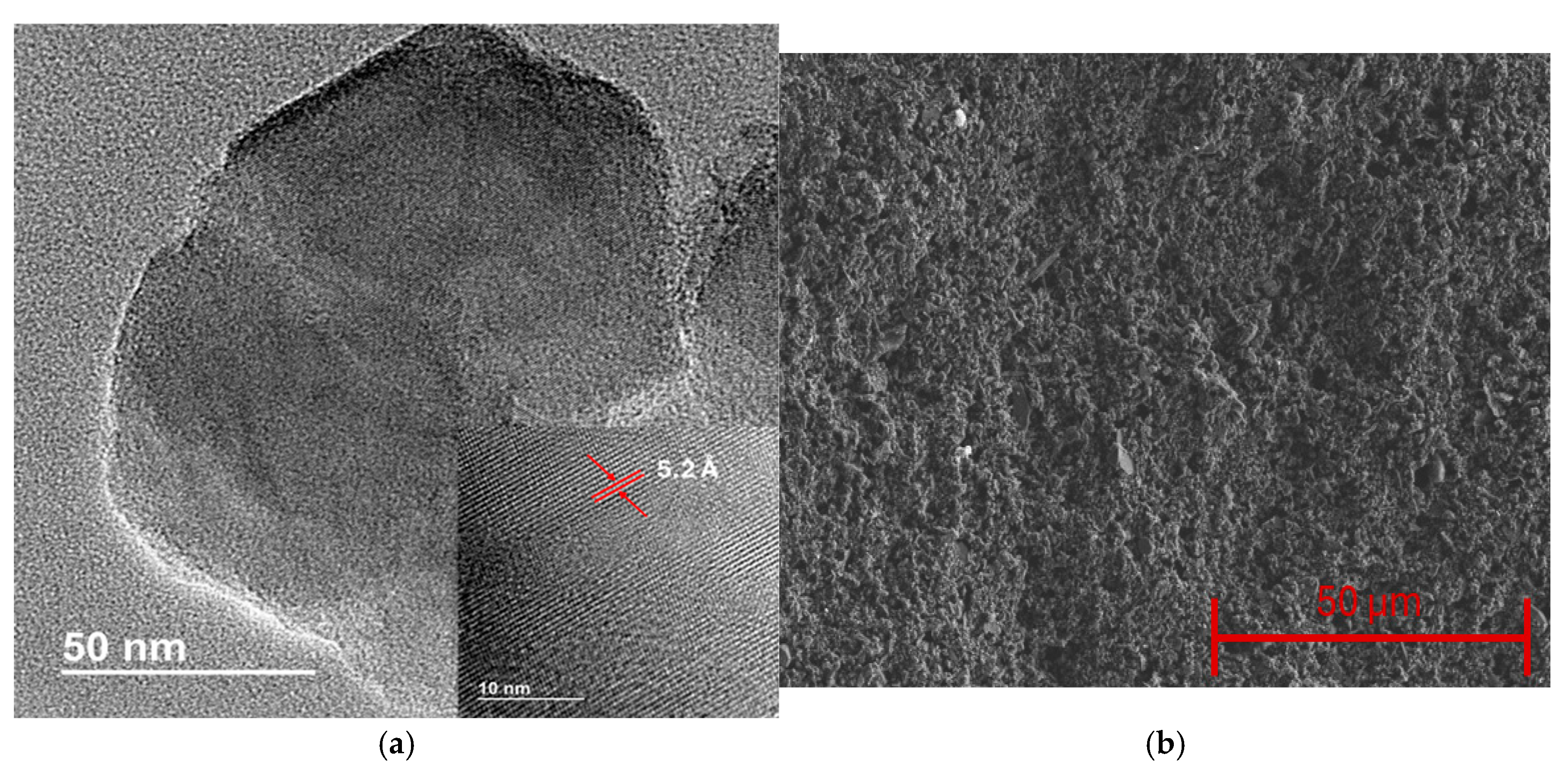
The physical and chemical properties of the synthesized borophene were analyzed through different experimental techniques. HRTEM was employed to study the morphological characteristics of the boron sheets. Figure 1a shows an example of the borophene sheets obtained, highlighting their reduced size, with an average lateral size of roughly one hundred nanometers. The inset in Figure 1a shows a magnified image, revealing the high crystallinity of the material and showing an average interlayer spacing of 5.2 Å. The HRTEM analysis confirms that the obtained nanomaterial consists of borophene nanoflakes with multiple layers, as evidenced by the interlayer spacing. Therefore, for better clarity, the term borophene in this work refers to few-layer boron nanoflakes [29]. Subsequently, pristine borophene thin films were deposited on quartz substrates, resulting in homogeneous coatings, as observed in Figure 1b.
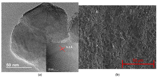
Figure 1.
(a) HRTEM image of borophene, the inset shows the high crystallinity of the nanomaterial and the interlayer distance. (b) SEM image showing the surface morphology of borophene thin films.
XPS was conducted to assess the surface chemistry following the sonochemical exfoliation of bulk boron. The pristine borophene was initially analyzed via XPS, revealing well-defined peaks corresponding to photoelectrons emitted from B 1s, O 1s, and C 1s core levels. As anticipated, boron was identified as the dominant element, consistent with the typical line profile typically reported for liquid-phase borophene [30].
Figure 2a illustrates the high-resolution B 1s spectrum, which was deconvoluted into three different components using a Gaussian–Lorentzian line shape. The components were centered at 187.6 eV, 189.1 eV, and 191.2 eV, representing 69.0%, 28.9%, and 2.1% of the total B 1s intensity, respectively. The component at the lowest binding energy (BE) and the highest intensity represents B–B bonds belonging to the β–rhombohedral framework. This observation confirms that the exfoliation process results in minimal incorporation of carbon- or nitrogen-related defects. The peak at 189.1 eV is attributed to interstitial sub-oxide BxOy (where x/y ≈ 3) [31,32], indicative of an early stage of borophene oxidation, likely introduced using isopropanol during the ultrasonication step [33]. The minor peak located at higher binding energy indicates the formation of a superficial sub-oxide BxOy (1.5 < x/y < 3) due to exposure to air. This slight oxidation may occur when coordinatively unsaturated boron atoms act as active sites for atmospheric oxygen, promoting a strong interaction between the two species [34]. Importantly, the absence of a fully oxidized B2O3 (x/y = 1.5) phase (BE ≈ 192.4 eV) indicates that complete oxidation has not occurred [35].

Figure 2.
XPS deconvoluted peaks of (a) B 1s, (b) O 1s, and (c) C 1s core levels for pristine borophene.
The O 1s spectrum (Figure 2b) was deconvoluted into five components. The two lowest BE components, centered at 529.1 eV and 530.9 eV, correspond to interstitial and surface BxOy species, respectively [32,33,35,36]. The components centered at 531.9 eV and 533.2 eV are associated with C=O and C–O bonds, which arise from atmospheric or solvent-derived carbonaceous residues. Finally, the component centered at 534.6 eV is attributed to hydroxyl (–OH) species on the nanolayers. The C 1s deconvolution (Figure 2c) revealed components centered at 284.8 eV, 286.3 eV, and 288.7 eV, which are assigned to C–C, C–O, and C=O groups, representing 74.3%, 18.9%, and 6.8% of the total C 1s signal, respectively. These carbon species likely originate from unavoidable surface contamination occurring during sample deposition and exposure to air.
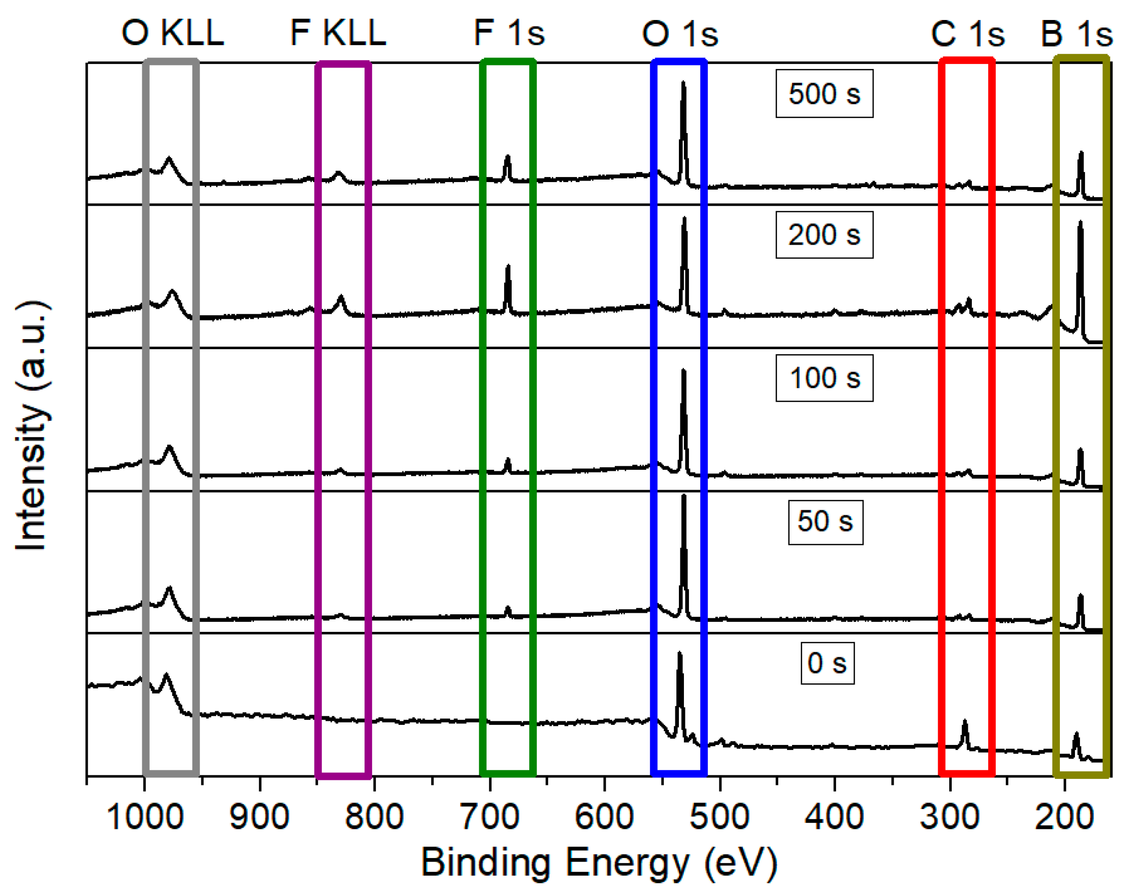
Subsequently, borophene samples were functionalized with fluorine species. Various plasma exposure times were employed (50 s, 100 s, 200 s, and 500 s) under a 100 W Ar/F2 discharge. Figure 3 presents a comparison of the survey spectra for the pristine and the fluorine-functionalized borophene samples. As anticipated, exposure of the nanomaterial to the Ar: F2 plasma resulted in the emergence of a distinct peak corresponding to F 1s at approximately 685 eV, along with the associated F KLL Auger peak around 832 eV. Table 1 summarizes the XPS-derived relative concentrations of the various elements for the samples depicted in Figure 3. Pristine borophene exhibits a significant amount of carbon, accompanied by minor traces of nitrogen, both of which significantly decrease upon plasma exposure. This reduction is likely attributable to the removal of carbonaceous species and hydrocarbons resulting from airborne contamination. The low quantities of sodium detected in all samples may be related to residuals from the synthesis process.
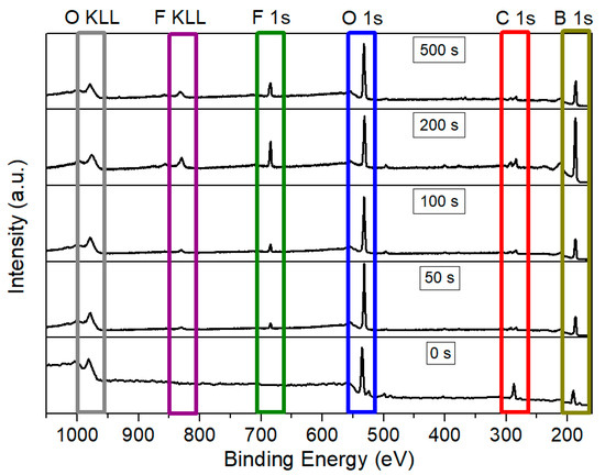
Figure 3.
Comparison of XPS survey spectra for pristine borophene and borophene functionalized with fluorine during 50 s, 100 s, 200 s, and 500 s of plasma exposure.

Table 1.
Summary of the atomic concentrations (in at. %) derived from XPS for pristine (0 s) and fluorinated borophene under constant 100 W power and varying plasma exposure times (from 50 to 500 s). The B/F ratio is also included as an indicator of the relative degree of fluorination.
Although nitrogen and sodium are not readily discernible in the survey XPS spectra due to their very low atomic concentration, both elements have been included in the quantification tables to provide a comprehensive and accurate representation of the surface composition.
It is noteworthy that even the shortest plasma exposure time of 50 s results in a detectable fluorine content of 1.8 at. %. Additionally, the Ar/F2 plasma treatment removes nearly 80% of the carbon content, likely due to the etching of carbon-based compounds that were initially grafted or adsorbed on the borophene surface. This effect is evident across all fluorinated samples and is accompanied by a relative increase in the boron signal, indicating the removal of undesirable atoms from the surface. Furthermore, the 50 s plasma exposure also led to an increase in the relative oxygen content. This may be attributed to the formation of unsaturated boron sites during the initial plasma exposure, which are not passivated by fluorine species. These sites subsequently react with O2 and H2O present when the plasma chamber was vented.
Extending the treatment time to 100 s results in an increase in fluorine concentration to 2.2 at. % and a reduction in oxygen concentration to 29 at. %, indicating that argon ion (Ar+) sputtering may facilitate the removal of the superficial suboxide layer present on the borophene surface. Concurrently, fluorine radicals are likely to interact with existing B–O bonds, potentially leading to the formation of B–O–F surface groups. Furthermore, the carbon content remains low and relatively stable at approximately 4%, suggesting that plasma treatment effectively eliminates the majority of surface-bound carbon species.
At a treatment duration of 200 s, the boron XPS signal increases to 81 at. %, while the oxygen content decreases further to 11 at. %, and fluorine concentration rises to 3.1 at. %. This observation implies that the plasma has nearly removed the initial superficial suboxide layer, indicating the introduction of a moderate density of B–F bonds. The decrease in the B/F atomic ratio, from 33 to 26, supports this trend and confirms a progressive fluorination process. From a practical perspective, the exposure duration of 200 s represents an optimal condition that balances effective fluorination and removal of oxidized surface species.
Notably, after 500 s of plasma treatment, the fluorine content continues to increase, reaching 4.7 at. %. However, oxygen concentration also rises to approximately 27 at. %. while boron decreases to around 64 at. %. This behavior may be attributed to prolonged ion bombardment, which could induce surface roughening [37] and a higher density of unsaturated sites [38]. Consequently, upon exposing the sample to ambient air, these reactive sites rapidly interact with atmospheric O2 and H2O, partly reconstituting a superficial suboxide layer. Trace elements such as N and Na remain relatively constant throughout the process, indicating that plasma primarily influenced the surface dynamics of boron, fluorine, and oxygen species.
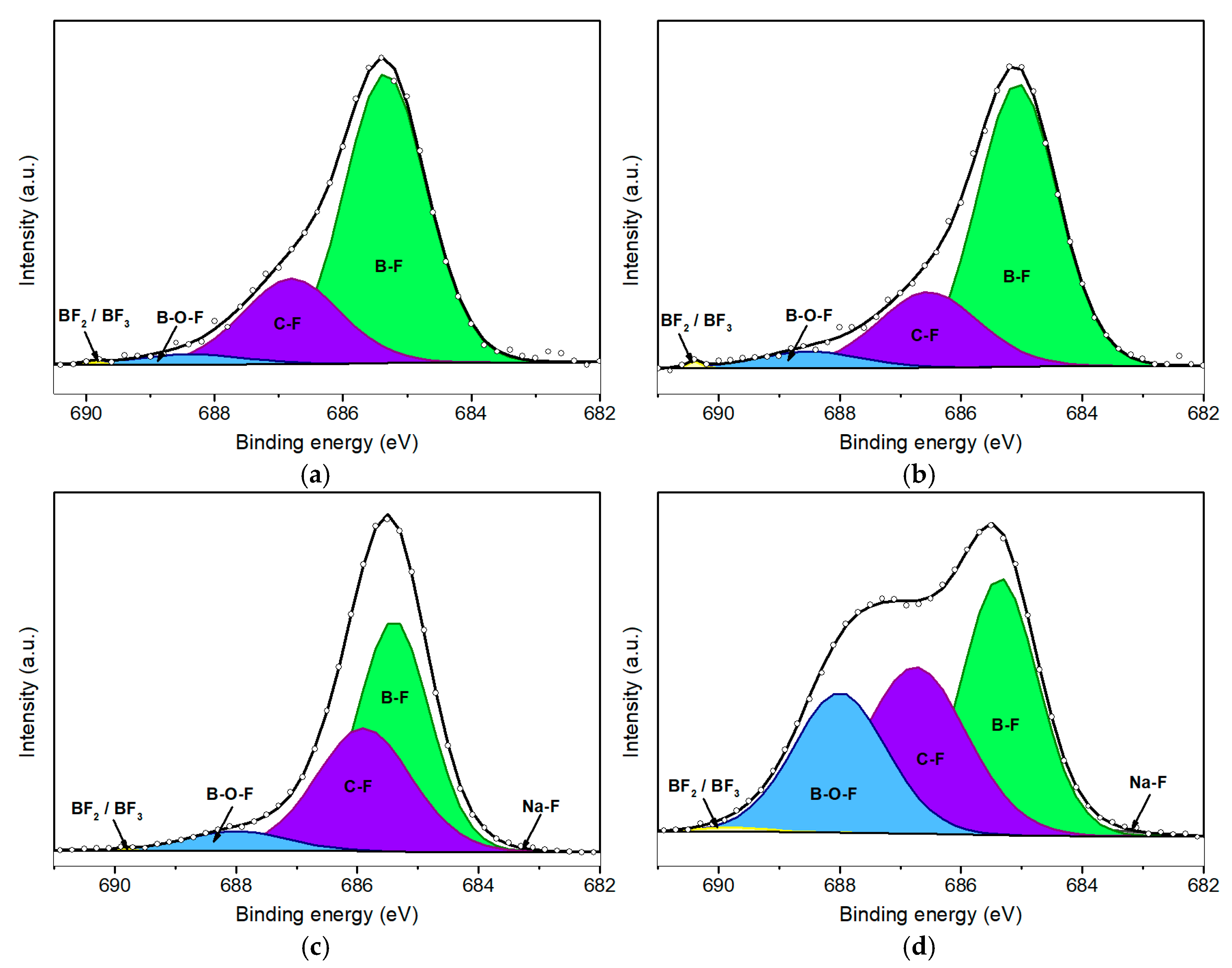
Figure 4 illustrates the F 1s XPS peaks corresponding to various durations of plasma treatment. Table 2 provides the relative area contributions (% A) of the deconvoluted components within the F 1s spectral envelope. As anticipated, the pristine borophene sample exhibited no detectable fluorine signal; however, a discernible F 1s peak emerged following just 50 s of plasma exposure. Notably, Figure 4d reveals a prominent shoulder at high binding energies, indicating the formation of an additional chemical environment for fluorine, likely associated with prolonged plasma exposure. This observation suggests the emergence of the B–O–F bond configurations, along with minor contributions from BF2 and BF3 species [26].
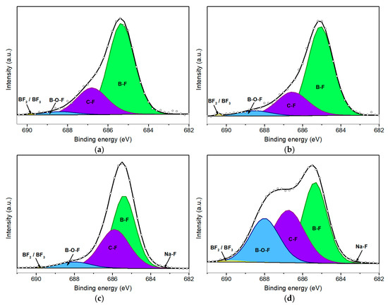
Figure 4.
Deconvolution of F 1s peaks for fluorinated borophene after 50 s (a), 100 s (b), 200 s (c), and 500 s (d) of plasma treatment.

At the lowest BE (around 684.0 eV), a minor peak associated with Na–F bonding is observed across all four fluorinated samples. This feature corresponds to bonds formed between fluorine and Na+ impurities, which are likely introduced during the synthesis and handling of the samples. However, the Na–F signal remains negligible and shows minimal variation across the different plasma treatment conditions.
A more pronounced peak appears at a slightly higher BE (685.1 eV), which is attributed to B–F bonding. This observation indicates that fluorine atoms are preferentially bonded to coordinatively unsaturated boron sites. Such bonding predominates at shorter plasma exposure durations, specifically at 50 s (Figure 4a) and 100 s (Figure 4b), where the B–F component accounts for approximately 70% of the total F 1s peak area. In contrast, for the sample subjected to 500 s of plasma exposure (Figure 4d), this proportion significantly decreases to approximately 38%, coinciding with an increase in the intensity of the component centered at 688.5 eV associated with the formation of B–O–F bonds.
Initially, the intensity of this component is relatively minor, increasing to a moderate level of 6% as shown in Figure 4c, which corresponds to 200 s of plasma treatment. However, when borophene is subjected to 500 s of plasma exposure, the area contribution (% A) of the component associated with B–O–F bonds increases to 25.6%, while the component associated with B–F bonds concurrently decreases. It is important to note that these B–O–F species are unlikely to form during plasma discharge. Instead, this configuration is probably formed after the post-treatment process, when samples containing fluorine species are exposed to ambient air. This suggests a sequential fluorination mechanism: in an initial stage, fluorine ions bind with boron atoms, forming B–F bonds. In a subsequent stage, with prolonged plasma exposure, argon ions (Ar+) sputter the nanomaterial, generating surface vacancies and B–F dangling bonds. These reactive sites then rapidly interact with atmospheric O2 and water vapor, leading to the formation of B–O–F species.
The C–F component observed at 686.5 eV indicates a similar post-exposure phenomenon. While plasma treatment likely removes a significant portion of surface carbon contamination, residual carbon impurities remain and can interact with fluorine ions during the plasma treatment. Furthermore, the vacancies and dangling bonds generated during plasma exposure facilitate reactions with atmospheric carbon species upon exposure to ambient air, thereby contributing to this component. It is important to note that the fluorination process remains within a low-functionalization regime, with an overall fluorine content of less than 5%. Consequently, fully fluorinated boron species, such as BF2 or BF3, are present in minimal quantities, accounting for less than 1% of the F 1s signal. Although in the F 1s spectrum of the sample subjected to 500 s of plasma exposure, there is a slight relative increase in this component, such an increase aligns with expectations given the higher fluorine amount.
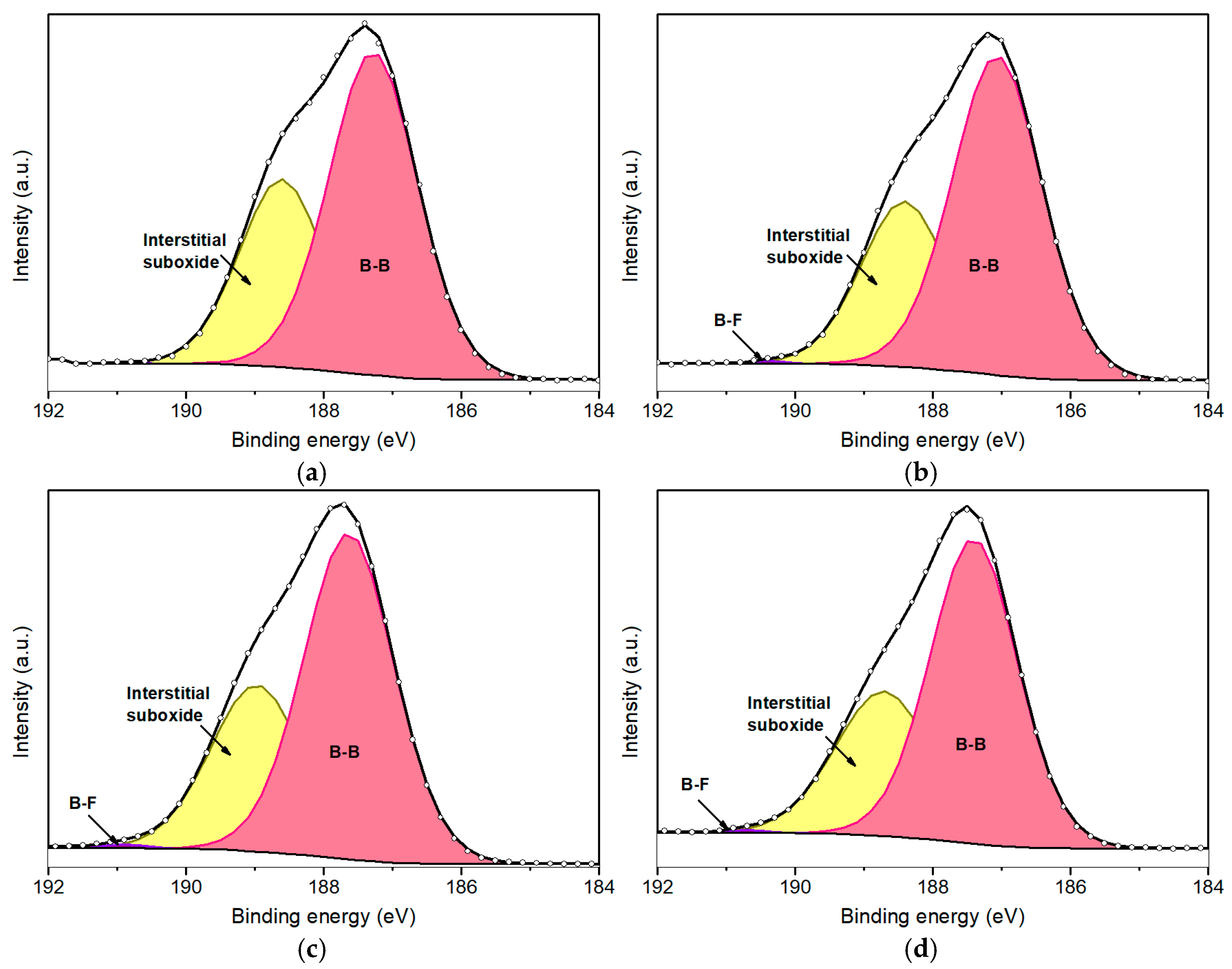
The B 1s peak further elucidates the fluorination process of borophene. Figure 5 presents the deconvoluted B 1s peaks for fluorinated borophene at various plasma exposure durations: 50 s (Figure 5a), 100 s (Figure 5b), 200 s (Figure 5c), and 500 s (Figure 5d). The B 1s peak was deconvoluted into four primary components (Table 3). The dominant component, consistently representing approximately 65–69% of the total area of the peak, is centered at the lowest BE and corresponds to B–B bonds [39]. This confirms that the β–rhombohedral phase remains largely intact, indicating that the fluorination strategy employed in this study effectively preserves the structural integrity and crystallinity of the boron sheets.
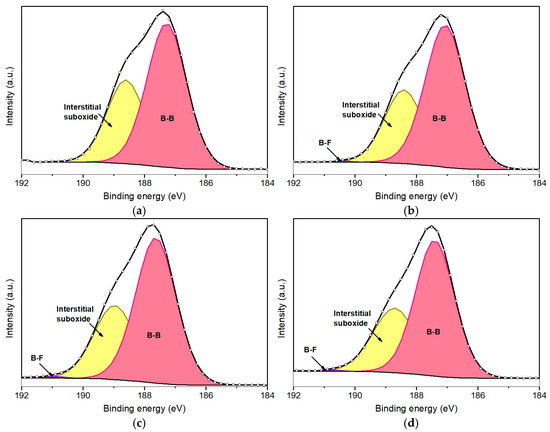
Figure 5.
Deconvolution of B1s peaks for fluorinated borophene after 50 s (a), 100 s (b), 200 s (c), and 500 s (d) of plasma treatment.

It is important to highlight that a minor component associated with B–F bonding is observed at approximately 190.7 eV. However, due to the relatively low concentration of fluorine and the predominant presence of boron and oxygen species, this peak remains minor and provides limited analytical insight. In this regard, the deconvolution of the F 1s peak proves to be more informative for characterizing the fluorination process.
Regarding the oxygen amount, a slight increase of approximately 5% was observed in the fluorinated samples compared to the pristine borophene. This increase is likely attributable to interstitial oxygen located between the borophene sheets. Although plasma treatment may disrupt some existing B–O bonds, it likely also facilitates the formation of boron vacancies and surface defects. Consequently, upon removal of the samples from the plasma chamber and exposure to ambient conditions, atmospheric oxygen can rapidly interact with these reactive sites, resulting in a moderate increase in oxygen content. Notably, this increase remains relatively consistent across the various plasma treatment durations, suggesting that the plasma-assisted fluorination protocol employed maintains a non-destructive interaction with the borophene structure. Overall, the lattice integrity and crystallinity appear to be preserved throughout the plasma treatment.
Summarizing, as the superficial thin suboxide layer formed upon exposure of borophene to air is almost all removed during brief plasma treatment durations, the associated component in the O1s spectrum at the highest BE has very low intensity. However, with prolonged exposure to plasma, a minimal signal reemerges, likely due to a slight increase in the density of reactive sites generated by extended ion bombardment. These unsaturated sites may subsequently oxidize upon exposure to oxygen in the air. Nevertheless, the highest observed contribution remains exceedingly low, at merely 0.4% of the total relative area, making this effect practically negligible. Importantly, even under the longest plasma treatment duration, there is no evidence in the O1s spectrum of a complete boron oxidation (i.e., formation of B2O3), which would appear at a higher BE.
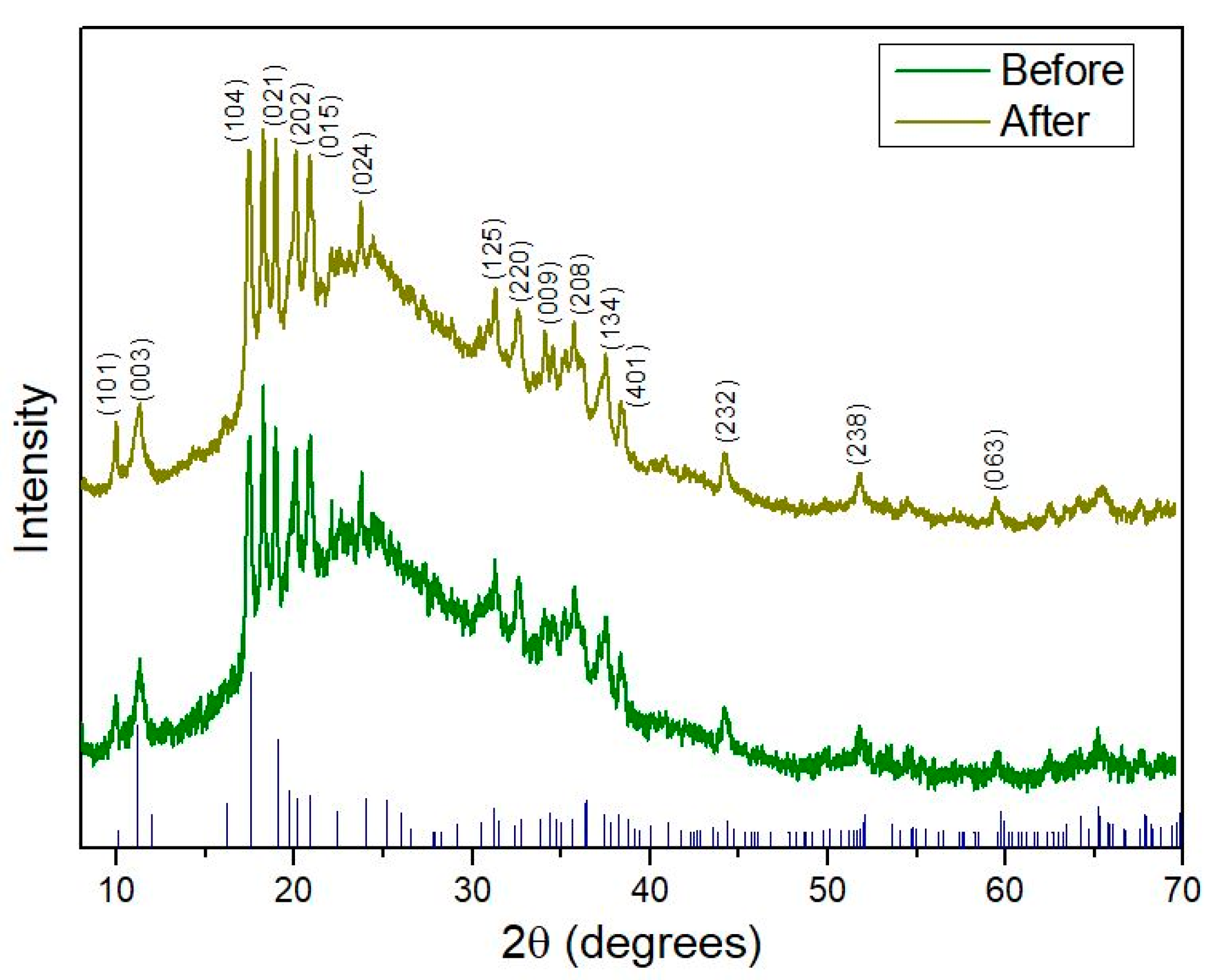
To further confirm that the fluorination process does not disrupt the crystal structure of borophene, additional experiments were performed. In this context, Figure 6 illustrates the XRD patterns recorded before and after plasma exposure. Notably, after fluorine functionalization, no significant differences were observed between the two spectra. This evidence indicates that the plasma functionalizing procedure employed does not damage or alter the crystallinity of the nanomaterial. Furthermore, the XRD data confirm that borophene retains a β–rhombohedral crystal structure (JCPDS 00-031-0207), indexed to the R–3m (no. 166) space group. This diffraction pattern corresponds to the β12 boron phase and agrees with previous studies [29]. Comparative analysis of the XRD patterns demonstrates consistent peak positions and relative peak shapes across all plasma treatment conditions, supporting the preservation of the β–rhombohedral crystal structure.
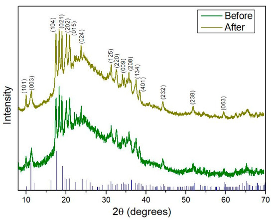
Figure 6.
XRD pattern comparison of borophene before and after fluorine plasma functionalization, along with the corresponding JCPDS reference peaks. The spectrum after plasma treatment corresponds to the sample irradiated for 200 s, selected to confirm that crystallinity is preserved under the plasma conditions considered optimal.
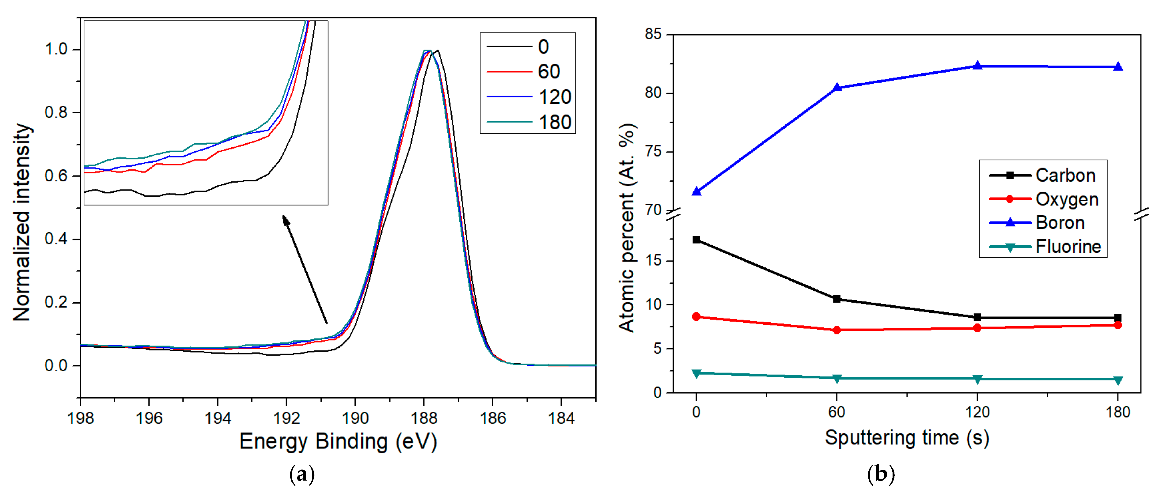
To gain a deeper understanding of the fluorine functionalization process in borophene, an XPS depth profile analysis was performed, monitoring the evolution of the relative areas of key elements at increasing depths. Figure 7a displays the B 1s peak for borophene exposed to 200 s of plasma treatment, acquired at the surface (0 s sputtering) and after 1, 2, and 3 min of sputtering, respectively. In this context, sputtering progressively etches the most superficial atomic layers, allowing access to information from deeper within the nanomaterial profile. Thus, longer sputtering durations can be taken as an indication of increased analysis depth, which facilitates the analysis of chemical changes across layers.
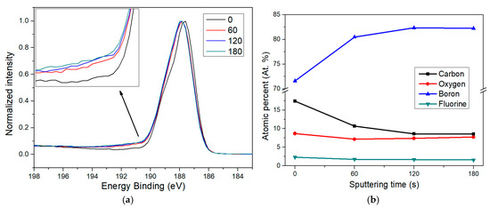
Figure 7.
XPS depth analysis of fluorine-doped borophene. Sputtering durations of 60, 120, and 180 s are compared to the pristine surface (0 s). (a) A shoulder feature attributed to B–F bonds becomes visible after sputtering, indicating that fluorine functionalization is present consistently below the initial surface impurities. (b) Elemental composition trends observed at increasing depths reveal how surface contaminants are removed and the borophene structure emerges progressively with higher sputtering times.
The inset in Figure 7a reveals that, following sputtering, there is an increase in the intensity of the B–F component around 190.7 eV, confirming that fluorine functionalization is not limited to the outermost borophene surface. As expected, the largest contrast occurs between the pristine sample and the one sputtered for 60 s. There is also a further increase in the B–F signal between 60 and 120 s, although the recorded spectrum at 180 s looks quite similar to that at 120 s. This observation aligns well with the depth-dependent elemental quantification shown in Figure 7b.
The most pronounced change happens from 0 to 60 s, where the carbon content drops significantly, indicating that most of the carbon contamination is confined to the surface and likely originates from ambient air exposure. Simultaneously, the boron signal increases sharply, while oxygen levels fall, probably due to the removal of adsorbed surface species and the partial etching of the superficial suboxide layer known to form on borophene after air contact. These trends continued slightly at 120 s, but by 180 s, no further major changes were observed. This suggests that after removing surface impurities, the doped borophene underneath becomes dominant and more chemically stable. It is also worth noting that the fluorine content remains relatively stable across the different depths, with only a slight and progressive decrease for longer sputtering times. This also suggests that after the plasma process, fluorinated borophene quickly interacts with environmental carbon and oxygen when exposed to ambient conditions, forming a suboxide layer again and grafting carbonaceous impurities onto the surface.
Regarding the interaction between fluorine and boron atoms, due to the high electronegativity of fluorine, it can form strong covalent bonds with boron atoms, which can significantly influence the surface charge distribution. This effect is especially relevant given the intrinsic electron deficiency of borophene, as the incorporation of fluorine increases local electron density and may stabilize the lattice electronically. Density functional theory (DFT) studies have reported that fluorination can lead to an increase in work function and introduce anisotropic modifications to the electronic structure [23,40] While further computational analysis would be necessary to confirm the precise charge redistribution mechanisms, current models support the idea that B–F bond formation partially compensates for the undercoordination typically observed in boron atoms in 2D borophene structures [41].
4. Conclusions
The functionalization of borophene with fluorine atoms results in a nanomaterial that is both chemically tunable and structurally robust, exhibiting considerable potential for diverse applications in gas sensing, flexible electronics, and catalysis. Analysis of the F 1s core-level spectra indicates a stepwise functionalizing mechanism, wherein fluorine initially interacts with coordinatively unsaturated boron atoms. As plasma exposure is extended, a secondary component associated with oxygen-containing species, specifically B–O–F configurations, becomes increasingly prominent. This transition implies a surface evolution influenced by subsequent exposure to ambient air, during which plasma-generated reactive sites rapidly engage with molecular oxygen (O2) and water vapour (H2O). Crucially, X-ray diffraction (XRD) and B 1s spectral analyses confirm that the β–rhombohedral structure of borophene remains intact throughout the fluorination process. The degree of fluorination achieved is maintained within the functionalization regime, reaching up to 5 at. %, while avoiding significant lattice disruptions. These findings highlight plasma-assisted fluorination as a precise and scalable method for tuning the surface properties of borophene, ensuring that its crystallinity is preserved.
Author Contributions
Conceptualization, J.C.-C. and C.B.; methodology, J.C.-C. and P.A.; validation, C.B.; formal analysis, J.C.-C.; investigation J.C.-C. and C.B.; resources, J.C.-C., P.A. and C.B.; data curation, J.C.-C.; writing—original draft preparation, J.C.-C.; writing—review and editing, J.C.-C., P.A. and C.B.; supervision, C.B.; project administration, J.C.-C.; funding acquisition, J.C.-C. All authors have read and agreed to the published version of the manuscript.
Funding
This research is funded by the Marie Skłodowska-Curie (Horizon Europe Programme) grant agreement No. 101066282—GREBOS.
Institutional Review Board Statement
Not applicable.
Informed Consent Statement
Not applicable.
Data Availability Statement
Dataset available on request from the authors.
Acknowledgments
The authors acknowledge financial support from the Marie Skłodowska-Curie (Horizon Europe Programme) grant agreement No. 101066282—GREBOS. The authors thank Rocio Garcia-Aboal for her assistance during the HRTEM image acquisition.
Conflicts of Interest
The authors declare no conflict of interest.
References
- Baig, N. Two-dimensional nanomaterials: A critical review of recent progress, properties, applications, and future directions. Compos. Part A Appl. Sci. Manuf. 2023, 165, 107362. [Google Scholar] [CrossRef]
- Torres, T. Graphene chemistry. Chem. Soc. Rev. 2017, 46, 4385–4386. [Google Scholar] [CrossRef]
- Minezaki, T.; Krüger, P.; Annanouch, F.E.; Casanova-Cháfer, J.; Alagh, A.; Villar-Garcia, I.J.; Pérez-Dieste, V.; Llobet, E.; Bittencourt, C. Hydrogen Sensing Mechanism of WS2 Gas Sensors Analyzed with DFT and NAP-XPS. Sensors 2023, 23, 4623. [Google Scholar] [CrossRef]
- Jain, A.; McGaughey, A.J.H. Strongly anisotropic in-plane thermal transport in single-layer black phosphorene. Sci. Rep. 2015, 5, 8501. [Google Scholar] [CrossRef]
- Cho, A.J.; Kwon, J.Y. Hexagonal Boron Nitride for Surface Passivation of Two-Dimensional van der Waals Heterojunction Solar Cells. ACS Appl. Mater. Interfaces 2019, 11, 39765–39771. [Google Scholar] [CrossRef] [PubMed]
- Hu, Y.; Chua, D.H.C. Synthesizing 2D MoS2 Nanofins on carbon nanospheres as catalyst support for Proton Exchange Membrane Fuel Cells. Sci. Rep. 2016, 6, 28088. [Google Scholar] [CrossRef]
- Kacem, K.; Ameur, S.; Casanova-Chafer, J.; Nsib, M.F.; Llobet, E. Bio-reduction of graphene oxide using pomegranate peels for NO2 sensing and photocatalysis applications. J. Mater. Sci. Mater. Electron. 2022, 33, 16099–16112. [Google Scholar] [CrossRef]
- Ramesh, A.; Mir, A. Influence of heteroatom doping on the quantum capacitance of phosphorene supercapacitors. J. Energy Storage 2022, 56, 106013. [Google Scholar] [CrossRef]
- Ambrosi, A.; Sofer, Z.; Pumera, M. Lithium Intercalation Compound Dramatically Influences the Electrochemical Properties of Exfoliated MoS2. Small 2015, 11, 605–612. [Google Scholar] [CrossRef] [PubMed]
- Yadav, A.; Kumar, H.; Shrama, R.; Kumari, R. Synthesis, processing, and applications of 2D (nano)materials: A sustainable approach. Surf. Interfaces 2023, 39, 102925. [Google Scholar] [CrossRef]
- Mishra, R.K.; Sarkar, J.; Verma, K.; Chianella, I.; Goel, S.; Nezhad, H.Y. Borophene: A 2D wonder shaping the future of nanotechnology and materials science. Nano Mater. Sci. 2024, 7, 198–230. [Google Scholar] [CrossRef]
- Cheng, T.; Lang, H.; Li, Z.; Liu, Z.; Liu, Z. Anisotropic carrier mobility in two-dimensional materials with tilted Dirac cones: Theory and application. Phys. Chem. Chem. Phys. 2017, 19, 23942–23950. [Google Scholar] [CrossRef] [PubMed]
- Xu, L.C.; Du, A.; Kou, L. Hydrogenated borophene as a stable two-dimensional Dirac material with an ultrahigh Fermi velocity. Phys. Chem. Chem. Phys. 2016, 18, 27284–27289. [Google Scholar] [CrossRef] [PubMed]
- Wang, Z.; Lü, T.Y.; Wang, H.Q.; Feng, Y.P.; Zheng, J.C. High anisotropy of fully hydrogenated borophene. Phys. Chem. Chem. Phys. 2016, 18, 31424–31430. [Google Scholar] [CrossRef]
- Casanova-Chafer, J. Roadmap for Borophene Gas Sensors. ACS Sens. 2025, 10, 76–99. [Google Scholar] [CrossRef]
- Mannix, A.J.; Zhou, X.F.; Kiraly, B.; Wood, J.D.; Alducin, D.; Myers, B.D.; Liu, X.; Fisher, B.L.; Santiago, U.; Guest, J.R.; et al. Synthesis of borophenes: Anisotropic, two-dimensional boron polymorphs. Science 2015, 350, 1513–1516. [Google Scholar] [CrossRef]
- Penev, E.S.; Kutana, A.; Yakobson, B.I. Can Two-Dimensional Boron Superconduct? Nano Lett. 2016, 16, 2522–2526. [Google Scholar] [CrossRef]
- Gupta, G.H.; Kadakia, S.; Agiwal, D.; Keshari, T.; Kumar, S. Borophene nanomaterials: Synthesis and applications in biosensors. Mater. Adv. 2024, 5, 1803–1816. [Google Scholar] [CrossRef]
- Feng, S.; Lin, Z.; Gan, X.; Lv, R.; Terrones, M. Doping two-dimensional materials: Ultra-sensitive sensors, band gap tuning and ferromagnetic monolayers. Nanoscale Horiz. 2017, 2, 72–80. [Google Scholar] [CrossRef]
- Shao, W.; Wang, H.; Zhang, X. Elemental doping for optimizing photocatalysis in semiconductors. Dalton Trans. 2018, 47, 12642–12646. [Google Scholar] [CrossRef] [PubMed]
- Hosseini, H.; Ghaffarzadeh, M. Surface functionalization of carbon nanotubes via plasma discharge: A review. Inorg. Chem. Commun. 2022, 138, 109276. [Google Scholar] [CrossRef]
- Vandenabeele, C.R.; Lucas, S. Technological challenges and progress in nanomaterials plasma surface modification—A review. Mater. Sci. Eng. R Rep. 2020, 139, 100521. [Google Scholar] [CrossRef]
- Qian, Y.Y.; Zheng, B.; Xie, Y.; He, J.; Chen, J.M.; Yang, L.; Lu, X.; Yu, H.T. Imparting α-Borophene with High Work Function by Fluorine Adsorption: A First-Principles Investigation. Langmuir 2021, 37, 11027–11040. [Google Scholar] [CrossRef]
- Struzzi, C.; Scardamaglia, M.; Casanova-Chafer, J.; Calavia, R.; Colomer, J.F.; Kondyurin, A.; Bilek, M.; Britun, N.; Snyders, R.; Llobet, E.; et al. Exploiting sensor geometry for enhanced gas sensing properties of fluorinated carbon nanotubes under humid environment. Sens. Actuators B Chem. 2019, 281, 945–952. [Google Scholar] [CrossRef]
- Peköz, R.; Konuk, M.; Kilic, M.E.; Durgun, E. Two-Dimensional Fluorinated Boron Sheets: Mechanical, Electronic, and Thermal Properties. ACS Omega 2018, 3, 1815–1822. [Google Scholar] [CrossRef]
- Morey, M.M.; Bahadur, R.; Li, Z.; Dharmarajan, N.P.; Fawaz, M.; Bandyopadhyay, A.; Chahal, S.; Ansah, S.; Singh Raman, R.K.; Terrones, M.; et al. Experimental Realization of Fluoroborophene. Small 2024, 21, 2407763. [Google Scholar] [CrossRef] [PubMed]
- Casanova-Chafer, J.; Bittencourt, C. Straightforward Synthesis of Borophene Nanolayers for Enhanced NO2 Detection in Humid Environments. ACS Appl. Electron. Mater. 2025, 7, 2305–2312. [Google Scholar] [CrossRef]
- Major, G.H.; Fernandez, V.; Fairley, N.; Smith, E.F.; Linford, M.R. Guide to XPS data analysis: Applying appropriate constraints to synthetic peaks in XPS peak fitting. J. Vac. Sci. Technol. A 2022, 40, 063201. [Google Scholar] [CrossRef]
- Zhang, F.; She, L.; Jia, C.; He, X.; Li, Q.; Sun, J.; Lei, Z.; Liu, Z.H. Few-layer and large flake size borophene: Preparation with solvothermal-assisted liquid phase exfoliation. RSC Adv. 2020, 10, 27532–27537. [Google Scholar] [CrossRef] [PubMed]
- Li, H.; Jing, L.; Liu, W.; Lin, J.; Tay, R.Y.; Tsang, S.H.; Teo, E.H.T. Scalable Production of Few-Layer Boron Sheets by Liquid-Phase Exfoliation and Their Superior Supercapacitive Performance. ACS Nano 2018, 12, 1262–1272. [Google Scholar] [CrossRef]
- Joshi, A.; Tomar, A.K.; Singh, G.; Sharma, R.K. Engineering oxygen defects in the boron nanosheet for stabilizing complex bonding structure: An approach for high-performance supercapacitor. Chem. Eng. J. 2021, 407, 127122. [Google Scholar] [CrossRef]
- Moddeman, W.E.; Burke, A.R.; Bowling, W.C.; Foose, D.S. Surface oxides of boron and B12O2 as determined by XPS. Surf. Interface Anal. 1989, 14, 224–232. [Google Scholar] [CrossRef]
- Gu, Q.; Lin, H.; Si, C.; Wang, Z.; Wang, A.; Liu, F.; Li, B.; Yang, B. Tuning the Active Oxygen Species of Two-Dimensional Borophene Oxide toward Advanced Metal-Free Catalysis. ACS Nano 2024, 18, 30574–30583. [Google Scholar] [CrossRef]
- Wang, L.; Xu, S.M.; Guan, S.; Qu, X.; Waterhouse, G.I.N.; He, S.; Zhou, S. Highly efficient photothermal heating via distorted edge-defects in boron quantum dots. J. Mater. Chem. B 2020, 8, 9881–9887. [Google Scholar] [CrossRef] [PubMed]
- Ong, C.W.; Huang, H.; Zheng, B.; Kwok, R.W.M.; Hui, Y.Y.; Lau, W.M. X-ray photoemission spectroscopy of nonmetallic materials: Electronic structures of boron and BxOy. J. Appl. Phys. 2004, 95, 3527–3534. [Google Scholar] [CrossRef]
- Matar, S.F.; Etourneau, J. Electronic and Magnetic Structures of New Interstitial Boron Sub-Oxides B12O2:X (X = B, C, N, O). Molecules 2021, 26, 123. [Google Scholar] [CrossRef]
- Cvelbar, U.; Pejovnik, S.; Mozetiè, M.; Zalar, A. Increased surface roughness by oxygen plasma treatment of graphite/polymer composite. Appl. Surf. Sci. 2003, 210, 255–261. [Google Scholar] [CrossRef]
- Nunomura, S. A review of plasma-induced defects: Detection, kinetics and advanced management. J. Phys. D Appl. Phys. 2023, 56, 363002. [Google Scholar] [CrossRef]
- Bignardi, L.; Pozzo, M.; Zelenika, A.; Presel, F.; Lacovig, P.; Lizzit, S.; Alfè, D.; Baraldi, A. Determining the atomic coordination number in the structure of β12 borophene on Ag(111) via X-ray photoelectron diffraction analysis. Surf. Interfaces 2024, 51, 104791. [Google Scholar] [CrossRef]
- Kistanov, A.A.; Cai, Y.; Zhou, K.; Srikanth, N.; Dmitriev, S.V.; Zhang, Y.W. Exploring the charge localization and band gap opening of borophene: A first-principles study. Nanoscale 2018, 10, 1403–1410. [Google Scholar] [CrossRef] [PubMed]
- Shahrokhi, M. Can fluorine and chlorine functionalization stabilize the graphene like borophene? Comput. Mater. Sci. 2019, 156, 56–66. [Google Scholar] [CrossRef]
Disclaimer/Publisher’s Note: The statements, opinions and data contained in all publications are solely those of the individual author(s) and contributor(s) and not of MDPI and/or the editor(s). MDPI and/or the editor(s) disclaim responsibility for any injury to people or property resulting from any ideas, methods, instructions or products referred to in the content. |
© 2025 by the authors. Licensee MDPI, Basel, Switzerland. This article is an open access article distributed under the terms and conditions of the Creative Commons Attribution (CC BY) license (https://creativecommons.org/licenses/by/4.0/).

