Article

Parametric Study of Proton Acceleration from Laser-Thin Foil Interaction

1
Institut für Optik und Quantenelektronik, Physikalisch-Astronomische Fakultät, Friedrich-Schiller-Universität, Max-Wien Platz 1, 07743 Jena, Germany
2
Helmholtz Institute Jena, Fröbelstieg 3, 07743 Jena, Germany
*
Author to whom correspondence should be addressed.
Plasma 2021, 4(4), 670-680; https://doi.org/10.3390/plasma4040034
Submission received: 5 August 2021 / Revised: 19 September 2021 / Accepted: 22 September 2021 / Published: 2 October 2021
(This article belongs to the Special Issue Laser–Plasma Interactions and Applications)

Abstract

:
We experimentally investigated the accelerated proton beam characteristics such as maximum energy and number by varying the incident laser parameters. For this purpose, we varied the laser energy, focal spot size, polarization, and pulse duration. The proton spectra were recorded using a single-shot Thomson parabola spectrometer equipped with a microchannel plate and a high-resolution charge-coupled device with a wide detection range from a few tens of keV to several MeV. The outcome of the experimental findings is discussed in detail and compared to other theoretical works.

1. Introduction

The acceleration of protons and ions during the interaction of high-power laser pulses with solid targets has been a well-investigated field since the first experimental study in the 1980s [1]. Thanks to the rapid advancement of high-power laser and optical technology, the focused intensities on targets exceed 10 18 W / cm 2 and the maximum kinetic energy of the accelerated protons reached tens of megaelectronvolts ( MeV ) [2]. The acceleration process occurs over a relatively very short length in the order of sub-millimeters and the generated proton beams possess high-emittance, laminarity and a short duration [3,4]. These characteristics of the proton beams generated from the interaction extend their huge potential in a plethora of applications, such as fusion energy [5,6], medical applications [7], isotope production [8] and astrophysical modeling [9,10].
Ion acceleration is the most efficient and is suitable for secondary applications when it is generated from the rear surface of the interacting solid target. Indeed, several models were proposed to describe the emission of the positively charged particles from the rear surface of the irradiated target, such as target normal sheath acceleration (TNSA) [11] and radiation pressure acceleration (RPA) [12], or even both in a hybrid acceleration scheme [13]. A detailed review of all the possible ion acceleration processes during laser–matter interaction can be found in review articles [4,14,15]. For laser intensities 10 19 W / cm 2 , the TNSA mechanism is the most dominant process; hence, we will focus on the TNSA process in this work. In this model, the fast electrons accelerated by the laser at the irradiated side propagate through and then exit the target, forming a dense sheath at the rear side of the foil. As a result, a huge electrostatic field in the order of TV / m is generated due to the charge separation of escaping electrons and the unbalanced charge left behind. This field can ionize and accelerate the atoms at the rear side of the target [11]. The accelerated ions and protons mainly originate from the hydrogen-rich contamination layer and water vapor at the target rear surface. TNSA generally produces broad Maxwellian-like proton and ion energy spectra with an exponentially decreasing profile with increasing ion energy [16], with a sharp cutoff. This was attributed to charge separation, which limits the ion velocities by forming a non-neutral electrostatic sheath, which diminishes the exponential density profile [17].
Since direct ion acceleration can not be yet realized directly by current laser technology, it has to rely on a driving electron component to transfer the energy from the laser to the ions. It has been found that the maximum energy of the accelerated protons is proportional to the temperature of the hot electrons creating the sheath as E proton β T hot [18]; the beta factor will be defined later for various parameters. Different models were suggested to explain the origin of the energetic electrons from the irradiated front side of the target, for example, collisional heating such as inverse bremsstrahlung, collisionless heating such as resonance absorption [19], vacuum heating [20] and pondermotive acceleration [21] depending on the laser and target parameters. When a high-intensity laser pulse reaches the target surface, the intense part of the pulse will not directly interact with the bulk material of the target, but with a pre-plasma generated by the advancing pedestal of the intensity profile of the laser due to the amplified spontaneous emission (ASE). If a p-polarized laser pulse is incident at an angle θ at a pre-plasma with a gradient length of λ g , the laser light will propagate up to the density n cr cos 2 θ before it is specularly reflected; as a result, the electric field vector E of the laser becomes parallel to the density gradient n . For relatively long λ g (sub-wavelength or larger), an electron plasma wave can be resonantly excited along the direction of the density gradient, and part of the laser energy is transferred to the electrons. This is called resonance absorption, [22] and the electron temperature scales as T hot ( I λ 2 ) 1 / 3 . For sharp density gradients, however, vacuum heating or Brunel absorption [20] becomes important; in this case, a strong energy absorption can be accounted for by the electrons that are dragged into the vacuum and then sent back into the plasma with velocities equivalent to the quiver velocity v osc = eE / m e ω . This mechanism is more efficient than resonant absorption for v osc / ω > λ g and the electron temperature scales as T hot ( I λ 2 ) α , where α > 1 . For relativistic laser intensities and relatively large plasma gradients, J × B heating [23], arising from the oscillating component of the ponderomotive force, greatly dominates. The temperature of hot electrons resulting from this mechanism is of the order of the ponderomotive potential with a scaling of T hot ( I λ 2 ) 1 / 2 [24]. However, the effectiveness of this absorption mechanism is reduced when a high-density plasma with a sharp gradient is present [22].
As briefly presented above, the experimental conditions greatly affect the temperature of the energetic electrons and subsequently the accelerated protons in a very dynamic environment with no clear boundaries between different mechanisms. The experimental conditions can also vary between different laser systems of similar characteristics. In the following, we present and discuss our experimental findings on the influence of different laser polarization ( P , S , and 45 ° ) on the number and energy of protons when varying laser intensity, pulse duration, and laser spot size are on the target.

2. Experiment

The experiments were carried out at the JETI40 laser facility at the Institute of Optics and Quantum Electronics at the University of Jena, Germany. The JETI40 laser system is based on chirped pulse amplification (CPA) technology with a center wavelength of 800 nm and can provide up to 650 mJ of pulse energy on target with a minimum pulse duration of 32 fs (FWHM). The pulse energy is monitored using a calibrated energy meter on a shot–shot basis. The polarization state of the laser was controlled by a 4-inch halfwave plate placed in the collimated beam before the focus. We considered the polarization state to be P- when the electric field component oscillates parallel to the plane of incidence, while S-polarized light oscillates perpendicularly to this plane. The laser pulses were focused using a 45 ° (f/1.2) off-axis parabola (OAP) onto an aluminum target with a thickness of 6 μ m . The focus spot size was 12 μ m 2 at ( 1 / e 2 ) , which accounts for an intensity above 1 × 10 19 W / cm 2 . The difference in reflectivity of the optics when changing the polarization state is about 1 % , which is in the same range of shot–shot fluctuations. The energy spectra of the protons emitted in the target normal direction were measured by a single-shot Thomson parabola spectrometer (TPS) equipped with a microchannel plate (MCP) and a high-resolution charge-coupled device (CCD) (see Appendix A). The TPS has an acceptance angle of 2 μ Sr and is capable of detecting protons with energy from 30 keV up to several MeV in a single shot. We also used a calibrated electron spectrometer [25] based on magnetic deflection with image plates to measure the temperature of the electrons along the target normal direction. This spectrometer has an acceptance angle of 0.3 mSr and can measure up to several of tens of MeV . A detailed schematic of the experimental set up is shown in Figure 1.

3. Results and Discussion

3.1. Intensity Scan

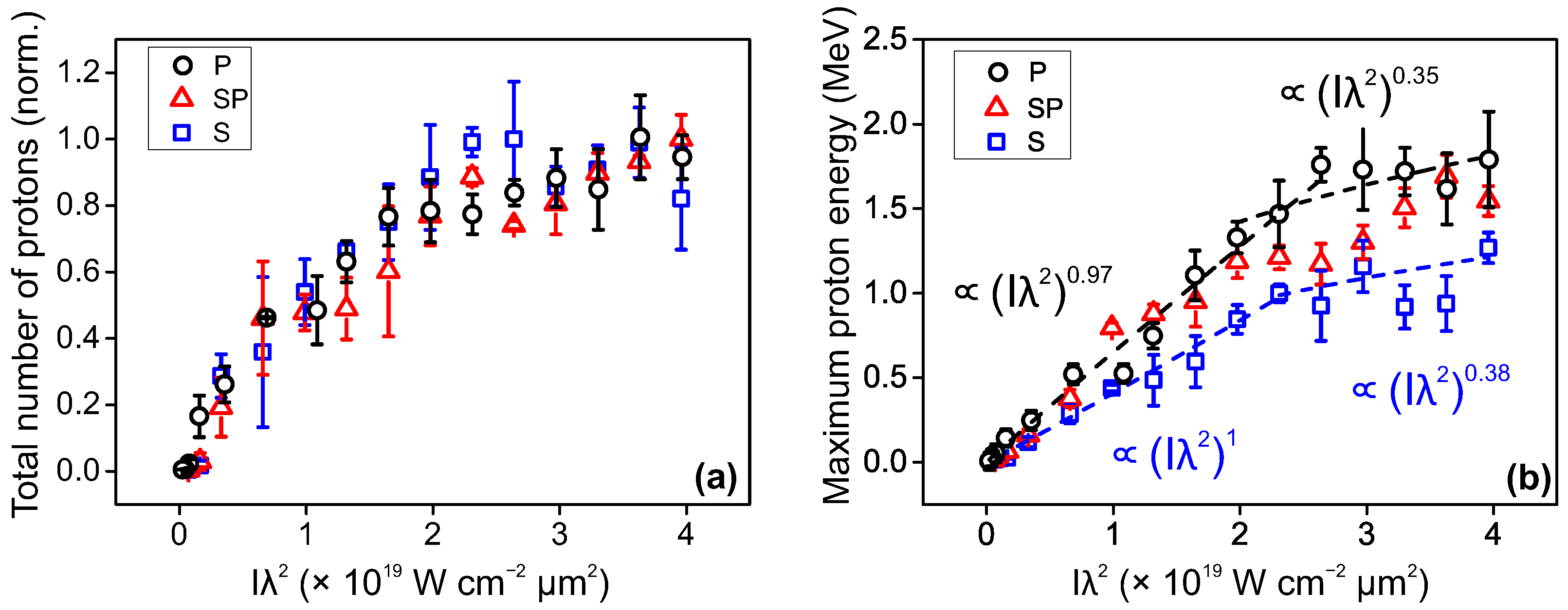
At first, we investigated the dependence of proton emission on laser intensity by varying the pulse energy on the target from 10 mJ up to 650 mJ in steps < 100 mJ while keeping the pulse duration and focus spot size fixed. We estimated the total number of protons collected by the TP for the energy range of 30 keV up to the maximum proton energy. In Figure 2a the integrated proton numbers for the three polarization states are presented. Error bars in all figures are due to shot–shot fluctuations. It can be seen that the total number of protons increases with laser intensity for all the polarization states. In fact, no significant difference can be observed in the proton number due to incident polarization, while the corresponding maximum proton energy presented in Figure 2b shows a clear preference for P-polarization state. To explain this observation, we take into account interaction parameters such as the intensity contrast ratio of the laser ∼ 10 6 at 10 ps and better than 10 10 at > 0.5 ns . By taking a pre-plasma expansion velocity of c s Z k B T e / m i with Z = 2 as the charge state of aluminum atoms ionized at the pre-pulse, k B T e < 0.1 keV and m i is the ion atomic mass of aluminum; we found a pre-plasma scale length of < 0.4 λ . At high intensities for oblique incidencse ( 45 ° ) of the laser pulse, P-polarization state has an electric field component directed parallel to the pre-plasma gradient n at the reflection boundary, whereas for S-polarization this condition is not fulfilled [22]. Thus, for P-polarization, the non-collisional heating absorption mechanisms such as vacuum heating and resonance absorption are both greatly enhanced in comparison to the case when using S-polarized light.
Furthermore, we can also see that the maximum proton energy for P-polarized incident light follows a power-law of ( I λ 2 ) α with α close to 1 for intensities up to 2.1 × 10 19 W / cm 2 . Thereafter, the power-law scaling reduces to α 0.35 . We can infer that vacuum heating is the dominant mechanism for heating electrons in the plasma at low intensities [26], while with increasing intensities, resonance absorption contributes stronger [22]. For S-polarization, we see a similar trend but with lower proton energies, although the conditions for the parallel electric field vector are not optimized for vacuum and resonance heating. In fact, the measured scaling of α = 0.38 sits in between resonance absorption, α = 0.3 [22] and ponderomotive heating, α = 0.5 [21]. With this conclusion, we are not ignoring the fact that pondermotively accelerated electrons mainly follow the laser propagation direction. For our experiment, it is 45 ° , which we experimentally measured and presented in a previous work [27]. Here, the angle of emission is still energy-dependent [28] and for low energy electrons they have a wider spread, which covers the target normal direction. These observations agree to some extent with the theoretical work of Y. Sentoku [29].
As mentioned in the introduction, the maximum proton energy is proportional to the temperature of the hot-electron generation in the plasma E proton β T hot . To quantify the factor β , we subsequently measured the temperature of the emitted electrons behind the target by inserting an electron spectrometer in the target normal direction (see Figure 1). The electron-energy spectra were taken at a maximum laser pulse energy of 650 mJ . After applying a Maxwellian-like fit, we found an electron temperature of T P = 0.46 MeV and T S = 0.29 MeV for lasers with P-polarization and S-polarization states, respectively (Figure 3). This makes the factor β P 4 have good agreement with Y. Sentoku’s work [29]. For the S-polarization state, the factor is slightly higher β S 4.1 .

3.2. Laser Pulse Duration Scan

Next, we fixed the laser energy at the maximum value and varied the temporal duration of the laser pulse and measured the corresponding maximum energy and number of protons. The scan range started from the optimized minimum pulse duration of 32 fs up to 180 fs . We employed an acousto-optic programmable dispersive filter (AO-PDF), also called a Dazzler device, to vary the group delay dispersion [30]. We employed Spider and Wizzler devices [31] to measure the pulse duration for different Dazzler parameters. Pulse duration measurements were carried out routinely during the experimental period. This was achieved by coupling out the low power laser beam immediately onto the devices placed outside the interaction chamber using a fused silica window of 0.15 mm thickness and known dispersion, which allowed us to calculate the pulse duration in the interaction chamber. Although a fused silica glass wafer of 500 μ m thickness was employed to protect the gold parabola from target debris, the induced pulse elongation is less than 0.18 % [32].
Taking a look at the recorded maximum proton energy presented in Figure 4, we can see a slight energy increase followed by a general down-trend with increasing pulse duration. This behavior agrees with the work in [33]. As mentioned before, the intensity was not kept constant when varying the pulse duration, but only the energy, which was set at the maximum value of 650 mJ . In the case of P-polarization—and less clearly in S and SP—we notice a maximum around 70 80 fs . After this peak, however, the energy decreases with the laser pulse duration with a scaling law of ( 1 / τ laser ) 0.5 . This is in agreement with the analytical model of a radially confined surface charge induced by laser-accelerated electrons on the target rear surface [34], as the laser energy E L = P L / τ laser is converted with an efficiency of η into hot-electron energy and subsequently into maximum proton energy as
E max = α · 2 m e c 2 η E L τ laser · P R 1 / 2
where P R = mc 3 / r e is the relativistic power unit, r e is the classical electron radius, η = 0.4 [35,36] is the conversion efficiency of energy transfer from laser into hot-electron, and E L and τ L are the laser energy and duration. We used a factor of α = 0.22 to obtain the same maximum proton energy of E p = 2.3 MeV , shown in Figure 4a at a pulse duration of τ laser = 70 fs . After substitution, the equation becomes equivalent to
E max = 4.45 × 10 20 [ J ] · ( 1 τ laser [ s ] ) 0.5
we used a quantity of 4.45 × 10 20 J in Equation (2) to fit the data in the case of P- and S-polarization states for the maximum proton energy after the peak at τ laser = 70 fs and indeed we obtain a scaling of ( 1 τ laser ) 0.5 .
On the other hand, when plotting the proton yield as a function of the laser pulse duration as seen in Figure 5, an uptrend is visible for all polarization states. The energy of the summed protons starts from the low energy threshold of the spectrometer 30 keV up to the maximum that is reported in Figure 4.
We compare our experimental findings with the theoretical estimation of the total number of protons given by the fluid model of Mora [37], and after some working we obtain
N p = n e c s t acc S sheath · e x p 2 E T hot | E max E min
where N p is the total number of accelerated protons over a given energy range, n e is the electron density, c s is the sound speed, t acc = a · τ laser is the acceleration time as discussed before [18] and S sheath is the sheath size at the target rear surface. We can see that the number of accelerated protons can increase with pulse duration as more electrons are involved in the light–energy conversion despite the lower maximum energy available for each particle. Using longer pulses can generate more protons; however, the acceleration time and the pulse energy are not infinite.

3.3. Laser Spot Size

In the next step, we fixed both the laser energy and the pulse duration while varying the laser spot size on the target. For that, we moved the target along the focus and as a result the intensity on the target varied with spot size w z . We measured the maximum proton energy at each target position, as seen in Figure 6. The highest proton energy was recorded when using the P-polarized light and the lowest energy for the S-polarization of the incident light. Furthermore, for all polarization states the protons gain maximum energy at the focus corresponding to the highest intensity. Beyond the Rayleigh range, the energy drops off exponentially. A short variation in the maximum proton energy compared to Section 3.1 is seen, which we attribute to the shot–shot fluctuations.
When estimating the proton yield recorded at each focal position as presented in Figure 7, we can see a double-peak structure around the zero position of the focus. Indeed this feature is evident for all polarization states and can be accounted for by the volumetric effect. Although the laser intensity decreases fast away from the focus, the irradiated area on the target is larger, meaning that a higher number of particles is involved at a given volume. This, however, is only applicable if the intensity is still sufficient to generate hot electrons to go through the target and to accelerate the protons at the rear surface. To test that, we employed a Gaussian fit to the experimental peaks and found out that the average position of the peak in the case of P-polarization is around ± 155 μ m and slightly larger for the S-polarization state around ± 220 μ m . Next, we calculated the equivalent intensity at this position assuming a Gaussian beam profile for the laser; w z = w 0 1 + ( z z R ) 2 with z R = 16 μ m is the Rayleigh length and w 0 is the beam radius at the focus. This gives an intensity which is slightly lower than 1 × 10 18 W / cm 2 . At such intensity, we used the equation T hot = κ ( I λ 2 ) α to estimate the temperature of the electrons, with κ being an experimental factor and α is a scaling factor which attributes the heating mechanism [38]. To set the factor κ , we used our experimentally measured value for the electron temperature of T hot = 0.46 MeV at the minimum focal spot position and the scaling of α = 0.35 . This gives κ 0.14 . Now we can estimate a temperature of T hot 0.1 MeV when the target is placed at the peak position. These hot electrons still have to be involved in creating a strong enough sheath field to ionize and accelerate the protons at the target rear surface using a simple equation to estimate the electric field of the sheath at the exit behind the target E TNSA = 2 k B T e e λ D [39], where k B T e is the temperature of electrons and λ D is Debye length. The (TNSA) electric field when the target is at the position where it gives the maximum proton number is 1 × 10 11 V / m , which is about one order of magnitude lower than its value at the focus z = 0 , yet it is still strong enough to ionize hydrogen atoms at the target side via barrier suppression of the atoms’ Coulomb field BSI [40] with a threshold electric field strength of E ion = π ϵ 0 ( U bind 2 = 13.6 eV ) e 3 · ( Z = 1 ) 10 10 V / m .
In the case of S-polarization, we used our experimental scaling α = 0.38 . By following a similar approach as in the case of P-polarization, we found that κ = 0.08 and the reduced electron temperature T e = 40 keV , which corresponds to a sheath field of E TNSA = 3 × 10 10 V / m , to be compared to 7 × 10 11 V / m at the focus position.
To elaborate more on the two-peak feature seen in the proton yield, we tried to calculate the TNSA electric field and the interaction volume at different target positions. We started with the TNSA field, which, as discussed before, depends on the electron temperature T e and the Debye length λ D = ϵ 0 k B T e e 2 n e , where ϵ 0 is vacuum permittivity and n e the electron density at the target rear surface neglecting recirculation [39]. To estimate the electron temperature behind the target, we first calculated it at the target front surface at different target positions (which corresponds to different laser intensities), using the same simple scaling as before, T e ( I λ 2 ) 0.35 0.38 . These electrons are then injected into the target where their energy decreases mainly due to collisional energy transfer to bound atomic electrons following “Bethe” theory [41]. The TNSA field is then calculated for each target position. As expected, the TNSA electric field decreases as the electron temperature quickly declines away from the focus position. We also added a field ionization threshold limit of 10 10 V / m for ionizing hydrogen atoms behind the target. The counteracting factor in our model is the increasing interaction volume of the incident laser pulse and the plasma created at the irradiated side of the target. We consider an interaction volume of V i n t e r = ( π w z 2 ) · ( t p r e c s ) , where π w z 2 is the focus spot size at the target and t p r e = 10 ps and c s are the pre-pulse time and pre-plasma expansion velocity, as introduced in Section 3.1. The product of ( E T N S A · V i n t e r ) , displayed in Figure 8, shows a similar behavior to the measured proton yield, especially when using the ionization limit of 10 10 V / m . It is worth mentioning that this simple model neglects some factors which are crucial for the laser–plasma interaction, for instance, the changing pre-plasma dynamics for different laser intensities as well as the interplay between different absorption mechanisms at different polarization states. To adequately tackle this task, however, extensive simulations are needed.

4. Conclusions

In summary, we have experimentally studied the effect of different laser parameters on the number and energy of accelerated protons during the interaction of high-intensity laser pulses with a thin aluminum foil. The total number of protons increased with laser intensity for all polarization states of the incident laser light. A slight saturation at intensities above 3 × 10 19 W / cm 2 was also observed. A similar trend was also observed in the case of maximum proton energy. The measured scaling of maximum proton energy to electron temperature comes around E p 4.1 T h o t , which agrees with theoretical work [29]. Further, we observed a slight increase in maximum proton energy when the laser pulse duration varied from 32 fs up to 70 fs . The reported energy peak was followed by a decrease in maximum proton energy with increasing laser pulse duration for all polarization states. For P- and S-polarizations, we obtained a scaling of E max ( 1 τ laser ) 0.5 . We also observed the uptrend of the total number of accelerated protons for longer laser pulses for all polarization states. Finally, we also varied the laser spot size on the target and observed the number of protons with respect to the spot size. We found a double peak structure away from the focus position for all polarization states due to the volumetric effect. It is important to carry out detailed parametric studies to understand the particle acceleration process for each laser system to find the optimal parameters for proton acceleration. Measuring the proton spectra along with the electron spectra enabled us to understand the dominating physical processes responsible for particle acceleration for the given laser parameters.

Author Contributions

Conceptualization, M.A. and A.G.; analysis, M.A. and S.M.; investigation, M.A., S.M. and A.G.; resources, B.B. and F.R.; writing—original draft preparation, M.A. and S.M.; review, A.G. and G.G.P.; supervision, A.G. and G.G.P.; project leader, G.G.P. All authors have read and agreed to the published version of the manuscript.

Funding

This research received no external funding.

Institutional Review Board Statement

Not applicable.

Informed Consent Statement

Not applicable.

Data Availability Statement

The data that support the findings of this study are available from the corresponding author upon reasonable request.

Conflicts of Interest

The authors declare no conflict of interest.

Appendix A

Appendix A.1. Thomson Parabola Spectrometer

The TP spectrometer consists of two parallel electric and magnetic fields. Both fields can be modified by changing the electric potential and varying the distance between the magnets, respectively. We measured a magnetic flux density of 110 mT using a Hall probe while the electric field was fixed at 42.5 kV / m . After exiting the deflection fields, protons and ions drift for 31 cm to hit a multi-channel plate (MCP) detector with a phosphor screen, such that the impact position and intensity can be imaged using a CCD. Since the TPS deflects the charged particles based on their q / m , the energy of each particle can be estimated from the deflection value x = q B 2 m E ( 1 2 L B 2 + L B D B ) where L B is the length of the magnet along the trajectory of the particle and D B is the distance between the end of the magnets and the MCP. The TPS was placed at 86.3 cm from the interaction point with an entrance of 1.35 mm , which gives 2 μ Sr as an angle of acceptance.

Appendix A.2. Proton Number Calibration

We used a nuclear track plate known as CR39 mounted in front of the MCP to calibrate the spectrometer. The CR39 is sensitive to ions with energies larger than 100 keV / nucleon , but insensitive to electrons and X-rays. After exposure, the CR39 plates need to be etched in NaOH solution at a temperature of ∼ 80 ° C for 60–80 min. After etching, the crater marks due to each proton impact become visible. Next, we counted the craters under a microscope in three different energy regions along the parabolic trace; low, medium, and high. The number of protons was counted inside a box with a size that is defined by the energy bin due to the lateral magnetic deflection with respect to the zero deflection point. In the end, we adjusted the intensity signal from the MCP by the average factor from the CR39. The high-energy cutoff was set as the signal starts to flatten due to the finite detection threshold of the MCP. Figure A1 shows a typical energy spectrum.
Figure A1. A typical energy spectrum for proton number per energy and solid angle.
Plasma 04 00034 g0a1

References

  1. Gitomer, S.J.; Jones, R.D.; Begay, F.; Ehler, A.W.; Kephart, J.F.; Kristal, R. Fast ions and hot electrons in the laser–plasma interaction. Phys. Fluids 1986, 29, 2679. [Google Scholar] [CrossRef]
  2. Wagner, F.; Bedacht, S.; Bagnoud, V.; Deppert, O.; Geschwind, S.; Jaeger, R.; Ortner, A.; Tebartz, A.; Zielbauer, B.; Hoffmann, D.H.H.; et al. Simultaneous observation of angularly separated laser-driven proton beams accelerated via two different mechanisms. Phys. Plasmas 2015, 22, 063110. [Google Scholar] [CrossRef]
  3. Cowan, T.E.; Fuchs, J.; Ruhl, H.; Kemp, A.; Audebert, P.; Roth, M.; Stephens, R.; Barton, I.; Blazevic, A.; Brambrink, E.; et al. Ultralow emittance, Multi-MeV proton beams from a laser virtual-cathode plasma accelerator. Phys. Rev. Lett. 2004, 92, 204801. [Google Scholar] [CrossRef]
  4. Macchi, A.; Borghesi, M.; Passoni, M. Ion acceleration by superintense laser-plasma interaction. Rev. Mod. Phys. 2013, 85, 751. [Google Scholar] [CrossRef] [Green Version]
  5. Roth, M.; Cowan, T.E.; Key, M.H.; Hatchett, S.P.; Brown, C.; Fountain, W.; Johnson, J.; Pennington, D.M.; Snavely, R.A.; Wilks, S.C.; et al. Fast Ignition by Intense Laser-Accelerated Proton Beams. Phys. Rev. Lett. 2001, 86, 436. [Google Scholar] [CrossRef] [PubMed]
  6. Belyaev, V.S.; Vinogradov, V.I.; Matafonov, A.P.; Rybakov, S.M.; Krainov, V.P.; Lisitsa, V.S.; Andrianov, V.P.; Ignatiev, G.N.; Bushuev, V.S.; Gromov, A.I.; et al. Excitation of promising nuclear fusion reactions in picosecond laser plasmas. Phys. At. Nucl. 2009, 72, 1077–1098. [Google Scholar] [CrossRef]
  7. Bulanov, S.S.; Brantov, A.; Bychenkov, V.; Chvykov, V.; Kalinchenko, G.; Matsuoka, T.; Rousseau, P.; Reed, S.; Yanovsky, V.; Krushelnick, K.; et al. Accelerating protons to therapeutic energies with ultraintense, ultraclean, and ultrashort laser pulses. Med. Phys. 2008, 35, 1770–1776. [Google Scholar] [CrossRef] [Green Version]
  8. Nemoto, K.; Maksimchuk, A.; Banerjee, S.; Flippo, K.; Mourou, G.; Umstadter, D.; Bychenkov, V. Laser-triggered ion acceleration and table top isotope production. Appl. Phys. Lett. 2001, 78, 595–597. [Google Scholar] [CrossRef] [Green Version]
  9. Belyaev, V.S.; Batishchev, P.A.; Bolshakov, V.V.; Elkin, K.S.; Karabadzhak, G.F.; Kovkov, D.V.; Matafonov, A.P.; Raykunov, G.G.; Yakhin, R.A.; Pikuz, S.A.; et al. Promising lines of investigations in the realms of laboratory astrophysics with the aid of powerful lasers. Phys. At. Nucl. 2013, 76, 404–422. [Google Scholar] [CrossRef]
  10. Remington, B.A.; Drake, R.P.; Takabe, H.; Arnett, D. A review of astrophysics experiments on intense lasers. Phys. Plasmas 2000, 7, 1641–1652. [Google Scholar] [CrossRef] [Green Version]
  11. Wilks, S.C.; Langdon, A.B.; Cowan, T.E.; Roth, M.; Singh, M.; Hatchett, S.; Key, M.H.; Pennington, D.; MacKinnon, A.; Snavely, R.A. Energetic proton generation in ultra-intense laser–solid interactions. Phys. Plasmas 2001, 8, 542–549. [Google Scholar] [CrossRef]
  12. Esirkepov, T.; Borghesi, M.; Bulanov, S.V.; Mourou, G.; Tajima, T. Highly Efficient Relativistic-Ion Generation in the Laser-Piston Regime. Phys. Rev. Lett. 2004, 92, 175003. [Google Scholar] [CrossRef] [Green Version]
  13. Higginson, A.; Gray, R.; King, M.; Dance, R.J.; Williamson, S.D.R.; Butler, N.M.H.; Wilson, R.; Capdessus, R.; Armstrong, C.D.; Green, J.S.; et al. Near-100 MeV protons via a laser-driven transparency-enhanced hybrid acceleration scheme. Nat. Commun. 2018, 9, 742. [Google Scholar] [CrossRef] [PubMed] [Green Version]
  14. Belyaev, V.S.; Krainov, V.P.; Lisitsa, V.S.; Matafonov, A.P. Generation of fast charged particles and superstrong magnetic fields in the interaction of ultrashort high-intensity laser pulses with solid targets. Phys.-Uspekh 2008, 51, 793–814. [Google Scholar] [CrossRef] [Green Version]
  15. Hiroyuki, D.; Nishiuchi, M.; Pirozhkov, A.S. Review of laser-driven ion sources and their applications. Rep. Prog. Phys. 2012, 75, 056401. [Google Scholar]
  16. Fews, A.P.; Norreys, P.A.; Beg, F.N.; Bell, A.R.; Dangor, A.E.; Danson, C.N.; Lee, P.; Rose, S. Plasma Ion Emission from High Intensity picosecond Laser Pulse Interactions with solid targets. Phys. Rev. Lett. 1994, 73, 1801–1804. [Google Scholar] [CrossRef] [PubMed]
  17. Pearlman, J.S.; Morse, R.L. Maximum expansion velocities of laser-produced plasmas. Phys. Rev. Lett. 1978, 40, 1652–1655. [Google Scholar] [CrossRef]
  18. Fuchs, J.; Antici, P.; D’Humières, E.; Lefebvre, E.; Borghesi, M.; Brambrink, E.; Cecchetti, C.A.; Kaluza, M.C.; Malka, V.; Manclossi, M.; et al. Laser-driven proton scaling laws and new paths towards energy increase. Nat. Phys. 2006, 2, 48–54. [Google Scholar] [CrossRef]
  19. Estabrook, K.; Kruer, W.L. Properties of resonantly heated electron distributions. Phys. Rev. Lett. 1978, 40, 42–45. [Google Scholar] [CrossRef]
  20. Brunel, F. Not-so-resonant, resonant absorption. Phys. Rev. Lett. 1987, 59, 52–55. [Google Scholar] [CrossRef]
  21. Wilks, S.C.; Kruer, W.L.; Tabak, M.; Langdon, A.B. Absorption of ultra-intense laser pulses. Phys. Rev. Lett. 1992, 69, 1383–1386. [Google Scholar] [CrossRef] [PubMed]
  22. Wilks, S.C.; Kruer, W.L. Absorption of ultrashort, ultra-intense laser light by solids and overdense plasmas. IEEE J. Quantum Electron. 1997, 33, 1954–1968. [Google Scholar] [CrossRef]
  23. Kruer, W.; Estabrook, K. J × B heating by very intense laser light. Phys. Fluids 1985, 28, 430–432. [Google Scholar] [CrossRef]
  24. Malka, G.; Miquel, J.L. Experimental confirmation of ponderomotive-force electrons produced by an ultrarelativistic laser pulse on a solid target. Phys. Rev. Lett. 1996, 77, 75–78. [Google Scholar] [CrossRef]
  25. Rosmej, O.N.; E Andreev, N.; Zaehter, S.; Zahn, N.; Christ, P.; Borm, B.; Radon, T.; Sokolov, A.; Pugachev, L.P.; Khaghani, D.; et al. Interaction of relativistically intense laser pulses with long-scale near critical plasmas for optimization of laser based sources of MeV electrons and Gamma-rays. N. J. Phys. 2019, 21, 043044. [Google Scholar] [CrossRef] [Green Version]
  26. Schnürer, M.; Kalashnikov, M.P.; Nickles, P.V.; Schlegel, T.; Sandner, W.; Demchenko, N.; Nolte, R.; Ambrosi, P. Hard X-ray emission from intense short pulse laser plasmas. Phys. Plasmas 1995, 2, 3106–3110. [Google Scholar] [CrossRef]
  27. Gopal, A.; Woldegeorgis, A.; Herzer, S.; Almassarani, M. Spatiotemporal visualization of the terahertz emission during high-power laser-matter interaction. Phys. Rev. E 2019, 100, 053203. [Google Scholar] [CrossRef]
  28. Cui, Y.Q.; Wang, W.; Sheng, Z.; Li, Y.; Zhang, J. Laser absorption and hot electron temperature scalings in laser–plasma interactions. Plasma Phys. Control. Fusion 2013, 55, 085008. [Google Scholar] [CrossRef]
  29. Sentoku, Y.; Bychenkov, V.; Flippo, K.; Maksimchuk, A.; Mima, K.; Mourou, G.A.; Sheng, Z.M.; Umstadter, D. High-energy ion generation in interaction of short laser pulse with high-density plasma. Appl. Phys. B 2002, 74, 207–215. [Google Scholar] [CrossRef]
  30. Verluise, F.; Laude, V. Huignard, J.; Tournois, P.; Migus, A. Arbitrary dispersion control of ultrashort optical pulses with acoustic waves. J. Opt. Soc. Am. B 2000, 17, 138–145. [Google Scholar] [CrossRef]
  31. Oksenhendler, T.; Coudreau, S.; Forget, N.; Crozatier, V.; Grabielle, S.; Herzog, R.; Gobert, O.; Kaplan, D. Self-referenced spectral interferometry. Appl. Phys. B 2010, 99, 7–12. [Google Scholar] [CrossRef]
  32. Boyd, R.W. Nonlinear Optics; Academic Press: Cambridge, MA, USA, 1992. [Google Scholar]
  33. Pirozhkov, A.S.; Mori, M.; Yogo, A.; Kiriyama, H.; Ogura, K.; Sagisaka, A.; Ma, J.-L.; Orimo, S.; Nishiuchi, M.; Sugiyama, H.; et al. Laser-driven proton acceleration and plasma diagnostics with J-KAREN laser. Proc. SPIE 2009, 7354, 223–232. [Google Scholar]
  34. Schreiber, J.; Bell, F.; Grüner, F.; Schramm, U.; Geissler, M.; Schnürer, M.; Ter-Avetisyan, S.; Hegelich, B.M.; Cobble, A.J.; Brambrink, E.; et al. Analytical model for ion acceleration by high-intensity laser pulses. Phys. Rev. Lett. 2006, 97, 045005. [Google Scholar] [CrossRef] [PubMed]
  35. Hatchett, S.P.; Brown, C.G.; Cowan, T.E.; Henry, E.A.; Johnson, J.S.; Key, M.H.; Koch, J.A.; Langdon, A.B.; Lasinski, B.F.; Lee, R.W.; et al. Electron, photon, and ion beams from the relativistic interaction of Petawatt laser pulses with solid targets. Phys. Plasmas 2000, 7, 2076–2082. [Google Scholar] [CrossRef] [Green Version]
  36. Yasuike, K.; Key, M.H.; Hatchett, S.P.; Snavely, R.A.; Wharton, K.B. Hot electron diagnostic in a solid laser target by K-shell lines measurement from ultraintense laser–plasma interactions (3 × 10²⁰ W/cm2, 400 J). Rev. Sci. Instrum. 2001, 72, 1236–1240. [Google Scholar] [CrossRef]
  37. Mora, P. Plasma expansion into a vacuum. Phys. Rev. Lett. 2003, 90, 185002. [Google Scholar] [CrossRef] [Green Version]
  38. Sheng, Z.-M.; Weng, S.; Yu, L.-L.; Wang, W.-M.; Cui, Y.-Q.; Chen, M.; Zhang, J. Absorption of ultrashort intense lasers in laser–solid interactions. Chin. Phys. B 2015, 24, 015201. [Google Scholar] [CrossRef]
  39. Roth, M.; Schollmeier, M. Ion Acceleration target normal sheath acceleration. CERN Yellow Rep. 2016, 1, 231. [Google Scholar]
  40. Augst, S.; Strickl, D.; Meyerhofer, D.D.; Chin, S.L.; Eberly, J.H. Tunneling ionization of noble gases in a high-intensity laser field. Phys. Rev. Lett. 1989, 63, 2212–2215. [Google Scholar] [CrossRef]
  41. Bethe, H.A. Zur Theorie des Durchgangs schneller Korpuskularstrahlen durch Materie. Ann. Phys. 1930, 397, 325–400. [Google Scholar] [CrossRef]
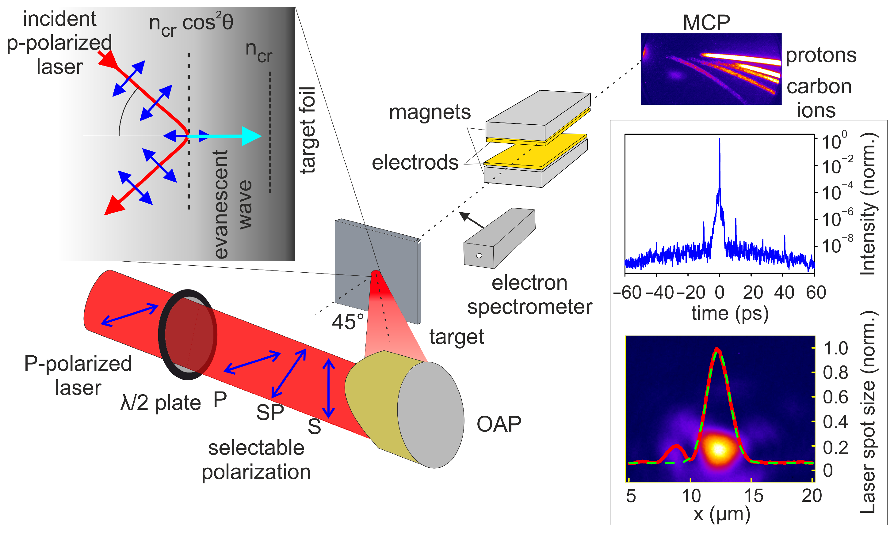
Figure 1. Schematic of the experimental setup. A halfwave plate inserted in the collimated beam path is employed to define the laser polarization state. Thereafter, the laser beam is focused onto an aluminum foil target of 6 μ m thickness using a 45 ° off-axis parabolic mirror. After the interaction, the charged particles accelerated along the target normal direction to enter the TP spectrometer through a 1 mm aperture. Here, the parallel electric and magnetic fields deflect them into parabolic trajectories with equal Z/m on the detection plane at the MCP. For recording the electron temperature, an electron spectrometer is inserted. The figure in the top-left inset shows the reflection of P-polarized laser on the pre-plasma profile at the target front surface. The figures on the right inset show measurements of the laser intensity contrast and the spot size.
Plasma 04 00034 g001
Figure 2. (a) Normalized proton numbers and (b) maximum proton energy as a function of laser intensity for P-, SP- and S-polarization. Dashed lines in (b) are power-law fittings.
Plasma 04 00034 g002
Figure 3. Electron spectra recorded along the target normal direction using a magnetic deflection spectrometer for P and S polarizations. Red (solid) lines represent the numerical fit between the peak and the high energy cut-off near the detection threshold. The spectra are presented in log-scale.
Plasma 04 00034 g003
Figure 4. Proton maximum energy as a function of laser pulse duration. (a) P-, (b) SP- and (c) S-polarization. Red (solid) line in (a,c) is a power-law fitting.
Plasma 04 00034 g004
Figure 5. Total number of protons as a function of laser pulse duration. (a) P-, (b) SP- and (c) S-polarization.
Plasma 04 00034 g005
Figure 6. The maximum proton energy as a function of the target position along the laser focus.
Plasma 04 00034 g006
Figure 7. Total number of protons as a function of the target position along the laser focus, blue (solid) line is a Gaussian peak fit. (a) P-, (b) SP-, (c) S-polarization. Red line in (a) represents laser spot size on target.
Plasma 04 00034 g007
Figure 8. Theoretical calculations for TNSA electric field at the target rear side (upper right) and the interaction volume at the target front side (bottom right) and their product (left).
Plasma 04 00034 g008
Publisher’s Note: MDPI stays neutral with regard to jurisdictional claims in published maps and institutional affiliations.