Article

Reducing the Transition Hysteresis of Inductive Plasmas by a Microwave Ignition Aid

Light Technology Institute, Karlsruhe Institute of Technology, Engesserstr. 13, 76131 Karlsruhe, Germany
*
Author to whom correspondence should be addressed.
Plasma 2019, 2(3), 341-347; https://doi.org/10.3390/plasma2030026
Submission received: 25 June 2019 / Revised: 7 August 2019 / Accepted: 9 August 2019 / Published: 16 August 2019

Abstract

:
Inductive plasma discharge has been a part of continuous investigations since it was discovered. Especially the E- to H-mode transition and the hysteresis behavior have been topics of research in the last few decades. In this paper, we demonstrate a way to reduce the hysteresis behavior by the usage of a microwave ignition system. With this system, a significant decrease of the needed coil current for the ignition of the inductive driven plasma is realized. For the microwave generation, a magnetron as in a conventional microwave oven is used, which offers a relatively inexpensive way for microwave ignition aid. At the measured pressure of 7.5 Pa, it was possible to reduce the needed coil current for the inductive mode transition by a factor of 3.75 compared to the mode transition current without the ignition aid. This was achieved by initiating the transition by a few seconds of microwave coupling. The performed simulations suggested that the factor can be further increased at higher pressures. That is especially interesting for plasmas that are hard to ignite or for RF-sources that cannot deliver high enough currents or frequencies for the ignition.

1. Introduction

Inductively-coupled plasmas (ICPs) are applied in a wide range of areas, from surface treatment to lighting applications. Since wide bandgap transistors made of semiconductor materials like SiC and GaN are available, it is possible to build highly-efficient inverters for a frequency up to 3 MHz [1]. Compared to the commonly-used frequency of 13.56 MHz, the needed coil currents for the ignition of 3-MHz-driven plasmas are drastically higher. In addition, the size of the coil used and the material that has to be ionized for the discharge are parameters with a large influence on the ignition current [2,3,4]. Therefore, the ignition behavior of this kind of plasma is investigated. A conventional magnetron was used for an additional power coupling to reduce the hysteresis behavior during the E- to H-mode transition. The results showed that due to the microwave ignition aid, the high frequency power source needs to deliver only the minimum maintenance current for the plasma ignition at a defined pressure.
The basis for the investigations was the model for the minimum ignition field according to Burm [2] and the analytical estimation of the minimum maintenance current according to Kortshagen [5]. The minimum ignition field approach is a relationship of the magnetic breakdown to the Paschen law. Usually, the Paschen law and the breakthrough condition are not used to describe the ICP ignition [6]. However, the theory can be justified by the results in Section 3. The chosen approach describes the minimum magnetic breakdown field B ign as:
B ign = B 0 p ω R [ l n ( A 0 π p R ) l n ( l n ( γ + 1 γ ) ) ]
where A 0 and B 0 are the Paschen parameters, which can also be used for inductive operation. The excitation frequency used is given by the angular frequency ω and the pressure p. The radius of the coil corresponds to R. Here, the radius of the plasma vessels r was chosen as nearly r R . The secondary electron emission coefficient γ originally described the generation rate of the secondary electrons at the electrodes [7]. Since there are no electrodes for inductive excitation, this value was set to γ = 1 e 1 to neglect the negative double-logarithmic term for the first approximation. A detailed derivation can be found in [2]. The calculated minimum ignition field B ign for the configuration used is shown in Figure 1.
The minimum maintenance current was approximated numerically. According to Kortshagen [5], with the known geometry and impedance Z of the system, the minimum maintenance current I min can be determined by calculating the electric field E 0 along the coil as:
I min = 2 L M | Z | 2 π R E 0
where L corresponds to half of the coil length and M to the winding density. For the calculation of the field E 0 , the Finite Element Method (FEM) software COMSOLTM (COMSOL AB, Stockholm, Sweden) was used [8]. This software includes a module for ICP simulations. In this article only the most important formulas used from the software to simulate the plasma parameters will be introduced. An exact overview of the main simulation theory can be found in [9]. The simulation was performed as a sweep over the pressure. The pressure dependence of the plasma parameters was then taken into account by the software. To estimate the minimum maintenance current I min , a set of plasma parameters is needed. To create this set, an external power has to be applied in the simulation. Therefore, the presented simulation yielded a solution that was not explicit. However, we found that if the minimum ignition current derived from B ign from Equation (1) was the base for the parameter calculation, the results delivered a good first step approximation for I min . To calculate the plasma properties, the following equations are solved:
n e t + · Γ e = R e ( u · ) n e Γ e = ( μ e E ) n e ( D e N e )
n ε t + · Γ ε + E · Γ e = S e n ( u · ) n ε + ( Q + Q g e n ) / q Γ ε = ( μ ε E ) n ε ( D ε N ε )
Equation (3) is used to calculate the time-dependent change of the electron density, where n e is the electron density, R e the rate of electron generation, μ e the electron mobility, E the electric field, D e the diffusion coefficient, and u represents the velocity vector of the neutral fluid (here Xenon). Equation (4) indicates the density of the electron energy. The symbols n ε , μ ε and D ε are given analogously to Equitation (3) for the energy density. Q and Q g e n are given by an external and a general heat source. In addition, q is given as the charge, and S e n indicates the energy change by inelastic collisions. In our simulation, the reactions in Table 1 were used. For both equations, the flux terms Γ e and Γ ε are directly given. To calculate the generation rate R e of electrons due to collisions and reactions, the cross-sections of the different Xenon species can be imported into the software. The elastic collision data from [10] and the excitation and ionization data from [11] were used.
The electromagnetic field is calculated through Ampere’s law, expressed as a function of the magnetic vector potential A, given as:
( j ω σ ω 2 ϵ ) A + × ( μ 0 1 × A ) = J e
where j is the imaginary unit, ϵ the permittivity, μ 0 the vacuum permeability, and J e the external applied current density. The plasma conductivity σ is calculated by:
σ = n e e 0 2 m e ( ν m + j ω )
where e 0 represents the electron charge, m e the electron mass, and ν m the momentum transfer frequency. Since a high-frequency sinusoidal excitation is used, a rapidly-changing magnetic field is induced in the coil. Following Faraday’s law, an electrical field dependent on the magnetic vector potential is induced:
E = j ω A
E 0 in Equation (2) is defined as the electrical field strength E at the location R. We simulated E 0 over the pressure and calculated the minimum magnetic maintenance field B main by the use of I min and the given coil configuration (see Section 2) as:
B main = μ r μ 0 M I min
The calculated ignition and maintenance fields are shown in Figure 1. The hysteresis behavior of the mode transition could be regarded as the difference of the fields.

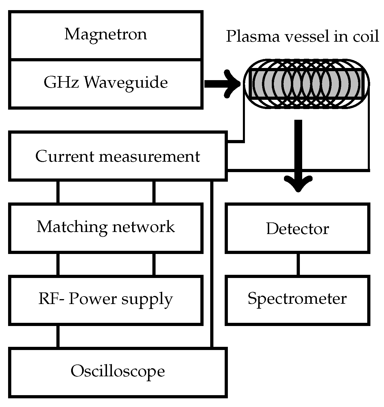
2. Experimental Setup

Figure 2 shows a scheme of the setup used. For the high-frequency power supply, an internally-developed inverter was used, which was presented in [1]. The output impedance was adapted to the inductive load with a matching network consisting of a tunable vacuum capacitor (500–1000 pF, WVS-Technology, Meerbusch, Germany). The coil current was measured with a wideband current monitor (Pearson Electronics, Palo Alto, CA, USA) directly at the coil input. The power output of the inverter, as well as the coil current were continuously monitored and recorded by an oscilloscope.
The operation took place in an air coil made of a copper tube with internal water cooling and different winding densities. For the investigations of the magnetic ignition behavior, a coil with n = 15, R = 30 mm and l = 100 mm was used. For the experiments using the microwave ignition aid, the coil had to be adapted to n = 26, R = 22.5 mm and l = 145 mm.
The plasma was generated in cylindrical quartz vessels within the coil. These were baked under vacuum and then filled with Xenon. The filling pressures were varied from 2.5 Pa–40 Pa. Here, glass vessels with l = 60 mm and r = 28.5 mm were used. For the studies with the use of microwaves, a glass vessels with l = 100 mm and r = 14.5 mm was used. The adaptation of the coil and the lamp vessel in the microwave investigations had to be done because an adjustment of the load during operation should be prevented. With the smaller dimensions and thus a smaller power density, the operation even in non-ideal operating points was possible. The hysteresis investigations were radiation-based. The mode transition was recorded by an array spectrometer (CAS 140CT, Instrument Systems, Munich, Germany), and the microwave generation was realized by a 500-W, 2.45-GHz magnetron (2M213, HITACHI, Chiyoda, Japan). The microwave radiation was then directed by a waveguide directly into the glass vessel.

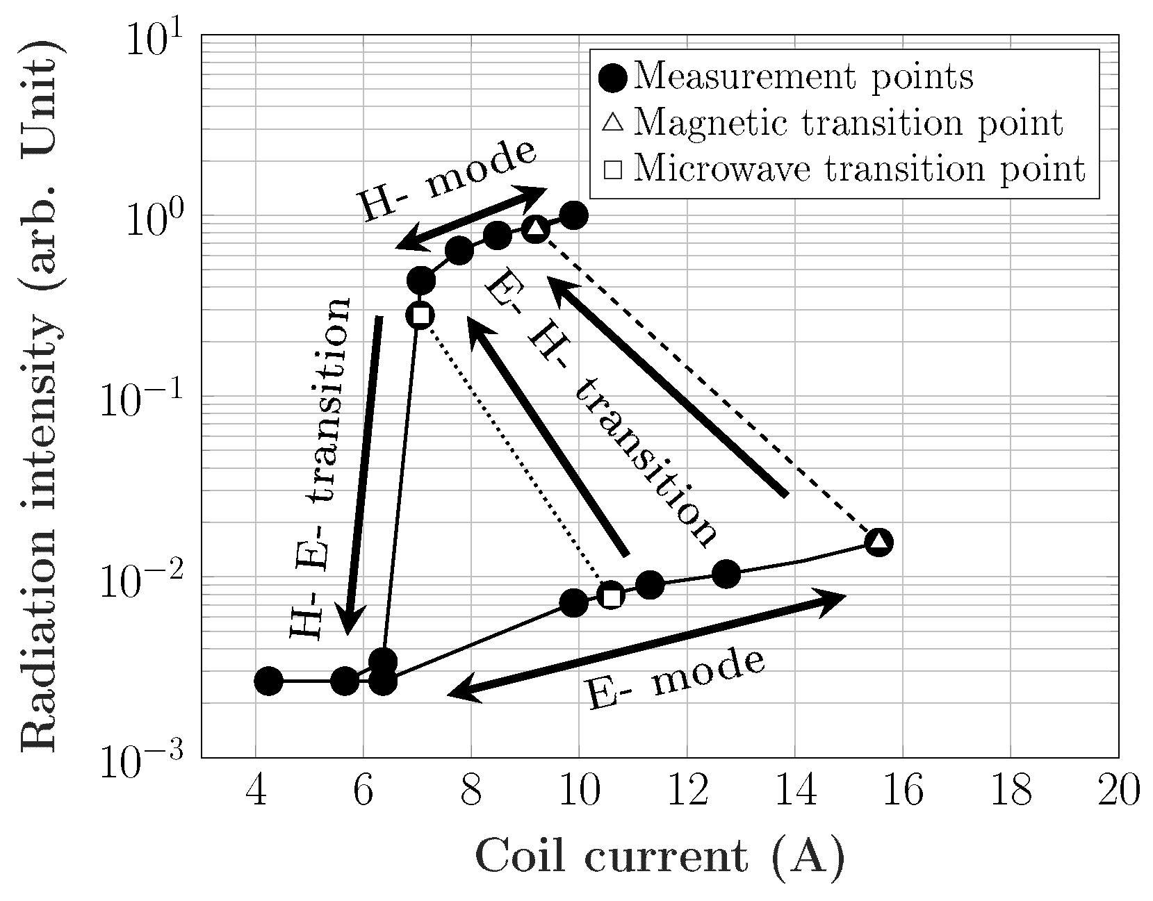
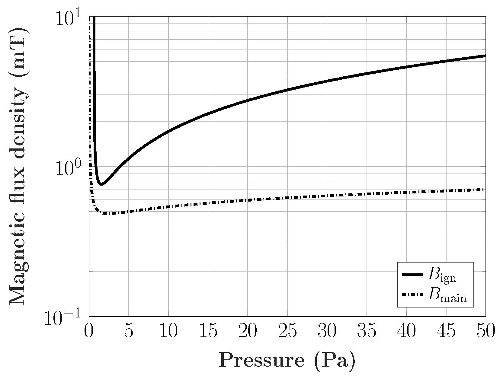
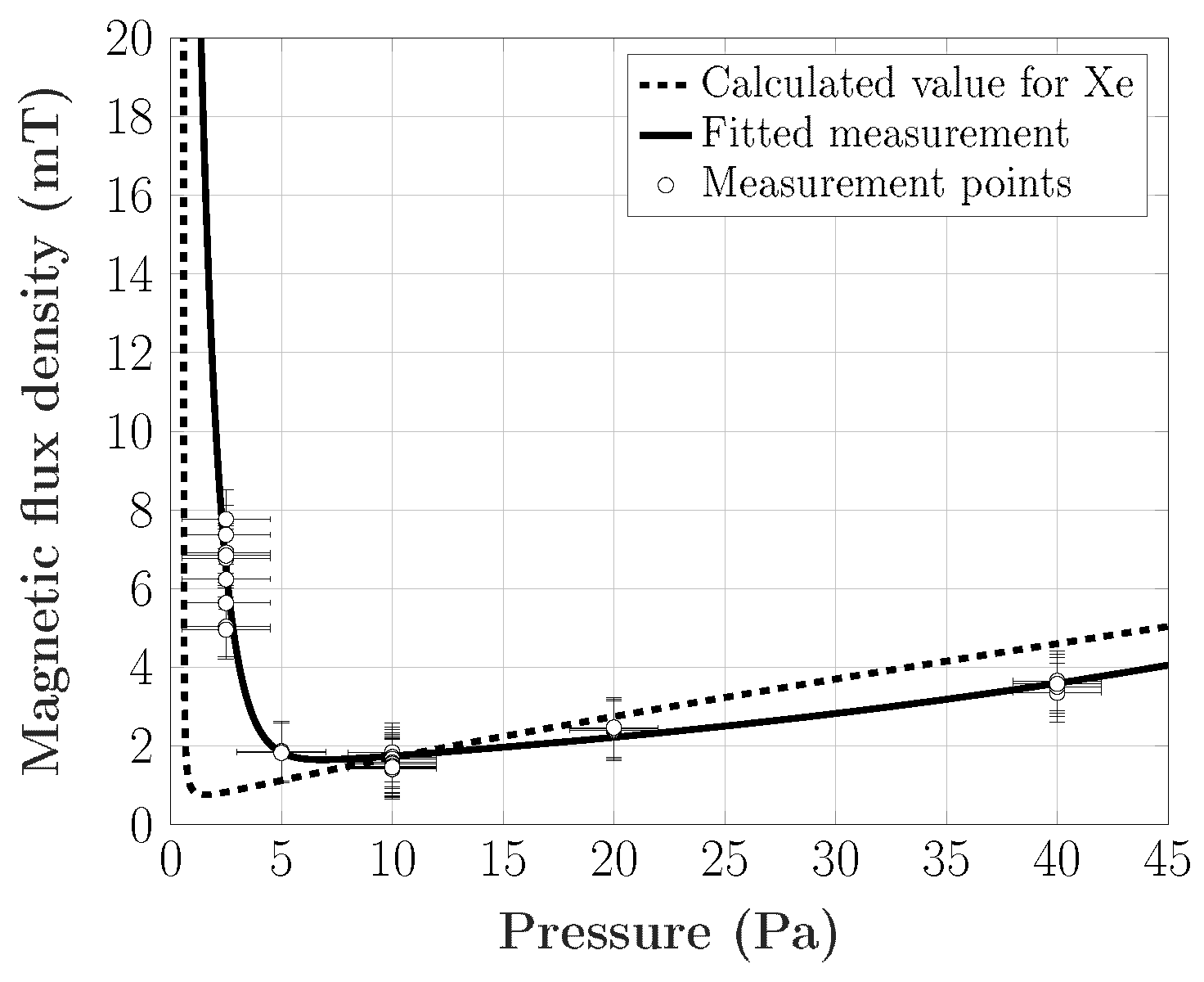
3. Results and Discussion

To validate Equation (1), the glass vessels with different Xenon pressures were placed in the coil. The coil current was slowly increased until the plasma mode transition occurred. The required ignition current was recorded by the oscilloscope. Since the ignition was based on statistical processes, this procedure was repeated several times for each pressure, and the mean value was built. The measurement results are shown in Figure 3.
The measurements showed that Equation (1) gave a good approximation to the calculation of the required ignition field. The deviations in the pressure range of <5 Pa were generated by the larger statistical distribution of the ignition points. In order to produce an even more precise curve, the measurements would have to be repeated more often and at even more pressure points. Furthermore, the uncertainty of ±2 Pa was caused by the pressure sensor and the filling station used. However, with those measurements, we found the minimum ignition field B ign at a pressure of 7.5 Pa Xenon. At this point, the severe error did not influence the ignition field since the slope of the measured curve was near the minimum here. With that pressure, a lamp for the hysteresis investigation was built. For the measurement in the first step, the normal ignition behavior was observed, as shown in Figure 4 (dashed line). Therefore, the coil current was increased stepwise, and the radiation output was detected. Without the microwave ignition aid, a common transition behavior was measured. That behavior is well known and often reported [5,12,13]. For the microwave ignition study, the coil current was increased stepwise, and the microwaves were coupled into the lamp vessel. Due to the additional power, the inductive discharge ignited even at low coil currents. In that case, the additional radiation output was not relevant and so is neglected in Figure 4. Without the additional power from the microwaves, the discharge at low coil currents fell back into E-mode. After the minimum maintenance current I min was exceeded, the inductive discharge stayed on (Figure 4, dotted line). The jump in the coil current was caused by the sudden decay in the impedance and was observed in both of the two ignition situations. The results showed that with the additional power from the microwaves, the needed E- to H-transition current was lowered to the minimal maintenance coil current I min . Therefore, if the setup were matched to the H-mode plasma impedance, the generated high-frequency coil current would be reduced to the minimum maintenance current I min . In that situation, also the E- to H-mode hysteresis was avoided. The lower transition point, which was reached with the microwave ignition aid, could be explained by the jump in the electron density during the additional power coupling. The power that could be absorbed by the plasma was proportional to the electron density [12]. If the power were increasing, a cut-off density would be reached. At this point, the capacitive power absorption was reduced while the inductive absorption was still increasing, and the E- to H-mode transition occurred [12]. In the case of a common inductive ignition, the cut-off electron density had to be reached only from the field generated by the coil. In view of the high currents, this represents a challenge to the technology, especially for hard ignitable plasmas. However, the presented pressure range has to be noted, so information on the scope of the validity of the statements made in this work is a subject of future research. In addition, investigations on the power coupling efficiencies of the microwaves have to be done to describe the power absorption more precisely.

4. Conclusions

In this paper, we calculated and measured the minimum magnetic breakdown field and the minimum maintenance field for an ICP Xenon discharge. We showed that a reduction or even the prevention of the transition hysteresis seen by the coil and the high-frequency inverter can be achieved by the use of a microwave ignition aid. With this system, it is possible to reduce the needed coil current significantly, which provides a great advantage for efficient operation of the inverter used. If the inverter used is switched on during the microwave ignition, it only has to be matched to the inductive discharge impedance. This prevents a matching to the E-mode and avoids an impedance tuning during the operation. Furthermore, the usage of a common 2.45-GHz magnetron is an inexpensive and simple way to realize an ignition aid for ICPs.

Author Contributions

Conceptualization, all; methodology, all; validation, all; formal analysis, all; investigation, all; data curation, T.G.; writing—original draft preparation, T.G.; writing—review and editing, all; visualization, T.G.; supervision, R.K.; project administration, R.K.; funding acquisition, R.K.

Funding

This research was funded in part by the European Union’s Horizon 2020 research and innovation program under Grant Number 641702.

Conflicts of Interest

The authors declare no conflict of interest.

References

  1. Denk, F.; Haehre, K.; Simon, C.; Eizaguirre, S.; Heidinger, M.; Kling, R.; Heering, W. 25 kW high power resonant inverter operating at 2.5 MHz based on SiC SMD phase-leg modules. In Proceedings of the PCIM Europe 2018; International Exhibition and Conference for Power Electronics, Intelligent Motion, Renewable Energy and Energy Management, Nuernberg, Germany, 5–7 June 2018. [Google Scholar]
  2. Burm, K. Breakdown magnetic field in an inductively coupled plasma. Phys. Lett. A 2008, 372, 6280–6283. [Google Scholar] [CrossRef]
  3. BURM, K.T.A.L. Breakdown minimum in magnetic field-driven metal plasmas. J. Plasma Phys. 2011, 77, 675–678. [Google Scholar] [CrossRef]
  4. BURM, K.T.A.L. Paschen curves for metal plasmas. J. Plasma Phys. 2012, 78, 199–202. [Google Scholar] [CrossRef]
  5. Kortshagen, U.; Gibson, N.D.; Lawler, J.E. On the E–H mode transition in RF inductive discharges. J. Phys. D Appl. Phys. 1996, 29, 1224–1236. [Google Scholar] [CrossRef]
  6. BURM, K.T.A.L. The electronic identity of inductive and capacitive plasmas. J. Plasma Phys. 2008, 74, 155–161. [Google Scholar] [CrossRef]
  7. Lieberman, M.A.; Lichtenberg, A.J. Principles of Plasma Discharges and Materials Processing, 2nd ed.; Wiley-Interscience: Hoboken, NJ, USA, 2005. [Google Scholar] [CrossRef]
  8. COMSOL. Multiphysics V. 5.4; COMSOL AB: Stockholm, Sweden. Available online: www.comsol.com (accessed on 25 June 2019).
  9. COMSOL. Plasma Module User’s Guide; COMSOL AB: Stockholm, Sweden, 2019; Available online: https://www.doc.comsol.com/5.4/doc/com.comsol.help.plasma/PlasmaModuleUsersGuide.pdf (accessed on 25 June 2019).
  10. SIGLO Database. Available online: www.lxcat.net (accessed on 25 April 2019).
  11. TRINITI Database. Available online: www.lxcat.net (accessed on 25 April 2019).
  12. Lee, M.H.; Chung, C.W. On the E to H and H to E transition mechanisms in inductively coupled plasma. Phys. Plasmas 2006, 13, 063510. [Google Scholar] [CrossRef]
  13. Turner, M.M.; Lieberman, M.A. Hysteresis and the E-to-H transition in radiofrequency inductive discharges. Plasma Sources Sci. Technol. 1999, 8, 313–324. [Google Scholar] [CrossRef]
Figure 1. Ignition field B ign and maintenance field B main over the pressure calculated for Xenon in a r = 28.5-mm vessel.
Plasma 02 00026 g001
Figure 2. Scheme of the setup used.
Plasma 02 00026 g002
Figure 3. Calculated ignition field B ign without microwave ignition aid from the current measurement for Xenon in a vessel with r = 28.5 mm and a coil with R = 30 mm, n = 15 over the pressure.
Plasma 02 00026 g003
Figure 4. Hysteresis behavior with and without microwave ignition. Measured as the radiation intensity in dependence of the coil current in a R = 22.5 mm, l = 145 mm and n = 26 coil.
Plasma 02 00026 g004
Table 1. The processes used in the Xenon discharge for the simulation.
No.ProcessReaction Δ ε (eV)
1Elastic X e + e X e + e
2Excitation X e + e X e * + e 8.31
3Superelastic collision X e * + e X e + e −8.31
4Ionization X e + e X e + + 2 e 12.1
5Step-wise ionization X e * + e X e + + 2 e 3.8

