Article

Analysis of the Preheating Phase of Micro-Arc Discharge in Seawater, Operated Using a Needle-to-Plane Electrode with Variation in the Tip Shape

1
Department of Electronic and Photonic Systems Engineering, Kochi University of Technology, Kami, Kochi 782-8502, Japan
2
Department of Electrical and Electronic Engineering, Meijo University, Nagoya, Aichi 468-8502, Japan
3
Center for Nanotechnology, Research Institute of KUT, Kochi University of Technology, Kami, Kochi 782-8502, Japan
*
Author to whom correspondence should be addressed.
Plasma 2019, 2(3), 303-315; https://doi.org/10.3390/plasma2030022
Submission received: 30 May 2019 / Revised: 27 June 2019 / Accepted: 5 July 2019 / Published: 8 July 2019

Abstract

:
In this work, micro-arc discharge is investigated using a needle-to-plane electrode system placed with a micro-gap in highly conductive artificial seawater. A major problem with microarc discharge is the erosion of electrodes caused by the high current of the arc; however, it was found that erosion of the needle electrode did not have any effect on the discharge process in the case of precise control of the discharge gap. A simple mathematical model was developed for a more detailed study of the preheating phase of the discharge. The modeling showed good agreement with the experimental results and confirmed that the needle electrode could be reused to generate reproducible micro-arc discharges even after the erosion caused by the arc. Moreover, it was found that, in certain conditions, the preheating phase could be simulated using a simple inductor-capacitor-resistor (LCR) oscillator model with a resistor instead of electrodes immersed in the liquid. It was confirmed that the shape of the needle electrode’s tip did not affect the measurement of optical emission spectra in the case of precise focusing, which could be used in the development of compact analytical tools for on-site analysis of deep-sea water using atomic emission spectroscopy.

Graphical Abstract

1. Introduction

Recently, plasma processes in liquids have been gaining a lot of attention owing to their wide range of possible applications, such as nanoparticle and nanocarbon production, water cleaning, plasma medicine, and plant growth promotion [1,2,3,4,5,6,7,8,9]. One promising application is the use of optical emission spectroscopy (OES) of various plasmas generated in liquid or in contact with liquid for elemental composition analysis of the liquid [10,11,12,13,14]. There are many methods for the generation of plasmas directly in liquids with low conductivity; however, reproducible generation of plasma directly in highly-conductive liquids is still challenging [5,14,15,16,17,18,19,20,21,22]. Moreover, for elemental composition analysis using OES, a strong intensity of optical emission is required [4,11,12,23,24,25,26]. Considering the requirements of strong optical emission and the possibility of generation of the plasma in highly-conductive liquid at high pressure, arc discharge is looking promising owing to the increase in the intensity of optical emission with the increase in pressure [12,15,24,27]. It was reported that micro-arc discharges could be reproducibly generated directly in highly-conductive liquids even at high pressures (up to 20 MPa) using a compact setup, which is essential for the development of compact analytical tools for on-site measurements in deep sea [15]. The compact tool for elemental composition analysis of seawater will be applied to numerous studies on oceanography, the exploration of marine resources, and ecological monitoring [28,29,30,31]. In recent study, it has been shown that OES of micro-arc discharges is advantageous for the detection of metal contaminants in seawater and could be applied to elemental composition analysis [24]. However, micro-arc discharges generated directly in liquids, especially highly-conductive liquids (such as seawater), have not been well studied and reproducible operations and reliable measurement are still a challenge [12,32,33].
The key feature of seawater is its high electrical conductivity. Due to the high conductivity, it requires a large current (typically more than 5 A) to apply the voltage required for breakdown [12,19,32,33]. The high current density passing through the liquid prior to discharge causes intense Joule heating of a small volume of liquid, resulting in the formation of microbubbles of vapor. After the formation of the bubbles, micro-arc discharge is generated in a gaseous medium inside the bubble [15,19,22,32,34,35]. For the operation of plasma in such highly-conductive liquid, it is advantageous to focus the current in the small volume within the micro-sized electrode to reduce the energy required for formation of the bubbles and breakdown [12,19,32]. A high current density during the micro-arc discharge results in significant damage to the electrodes due to erosion [12,15,32,36]. For reproducible micro-arc discharge and reliable OES measurement, it is necessary to study the effect of the erosion of the electrode’s tip on the discharge process.
The most significant changes in the discharge conditions induced by erosion are an increase in the gap length and variation in the electrode’s tip shape. The gap length can be easily adjusted using a micromanipulator before each discharge. However, the variation in the tip shape caused by erosion cannot be controlled reproducibly. For practical application and the development of an on-site measurement tool with a sufficient lifespan, it is necessary to understand the effect of the variation of the tip shape on the plasma generation and discharge parameters. From our previous experiments, it was found that a hemisphere-shaped needle tip was quickly deformed into a flat edge of cylinder after several shots of micro-arc discharges. In this study, the effect of the tip shape on the preheating phase of the discharge was investigated by experiments and numerical modeling. The ignition process of micro-arc discharge in seawater can be divided into two main steps: Preheating in liquid medium with formation of the bubbles and arc discharge in a gaseous medium. Considering that the arc discharges in a gaseous medium have been studied extensively, this study mostly focuses on the preheating of seawater within the electrode gap required for the formation of the bubbles.

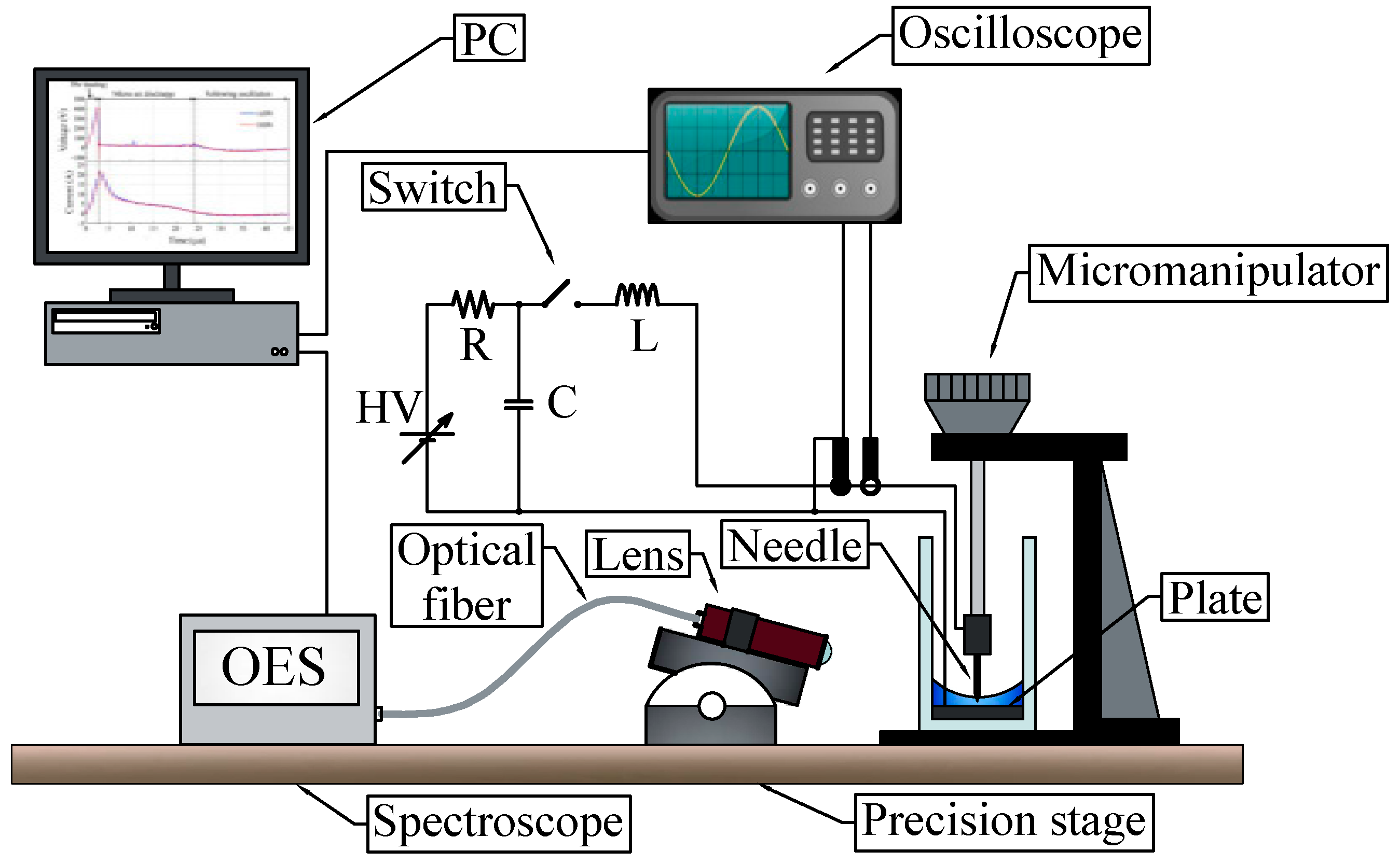
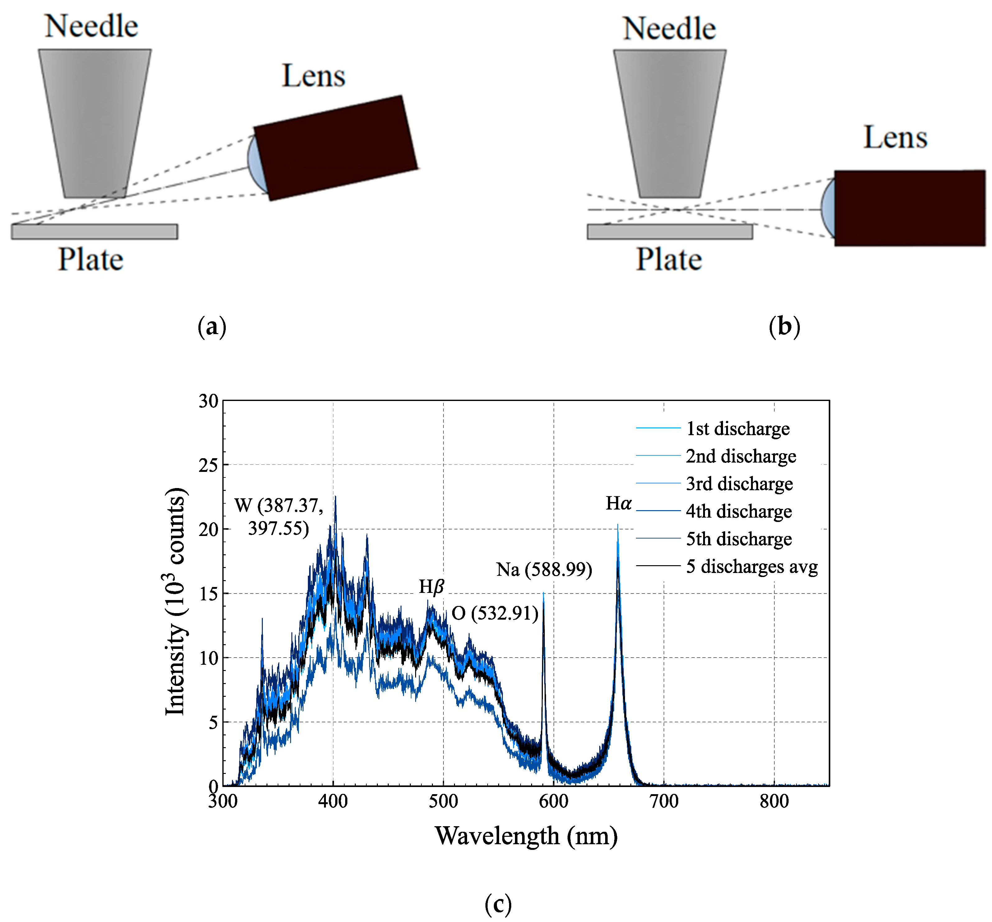
2. Materials and Methods

Artificial seawater composed of 10 typical components (10ASW, electrical conductivity 45.1 mS/cm at 20.3 °C) was used for the experiments. Elemental composition of the 10ASW is shown in Table 1.
A schematic of the experimental setup is given in Figure 1. For generation of microplasma discharge, the needle-to-plane electrode system, consisting of a W needle electrode (W20-05-10 × 1½”, NPS Inc., Tokyo, Japan) and polished Pt plate were used. The plane electrode was placed on the bottom of a quartz cuvette of 18 mm x 18 mm inner size, in which 1 mL of 10ASW was introduced, resulting in 2 mm water depth at the center and about 4 mm in area of the wall inside the cuvette due to the surface tension effect. The discharge gap was precisely controlled using a micromanipulator.
An impulse generator, consisting of a capacitor C = 47–220 nF, an inductor L = 47–330 µH, and a MOSFET switch, was used to supply a current pulse. The capacitor was charged by a DC power supply, with the resulting voltage in the range of 580‒750 V. During the discharge, the MOSFET switch was closed to apply a current pulse to the discharge gap. The voltage and current waveforms were stored in a digital oscilloscope with a high-voltage probe and a current probe. The OES spectrum from the plasma was collected by a quartz lens and recorded by multi-channel spectrometer (USB4000, Ocean Optics, Largo, FL, USA) through a quartz optical fiber.

3. Results and Discussion

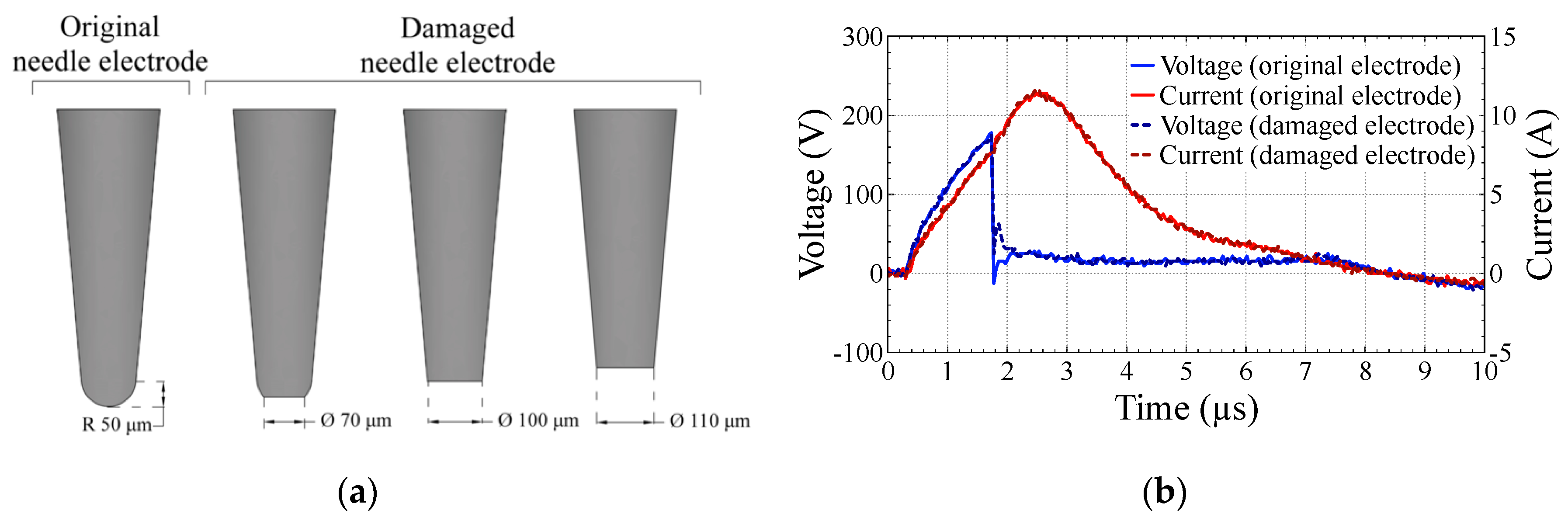
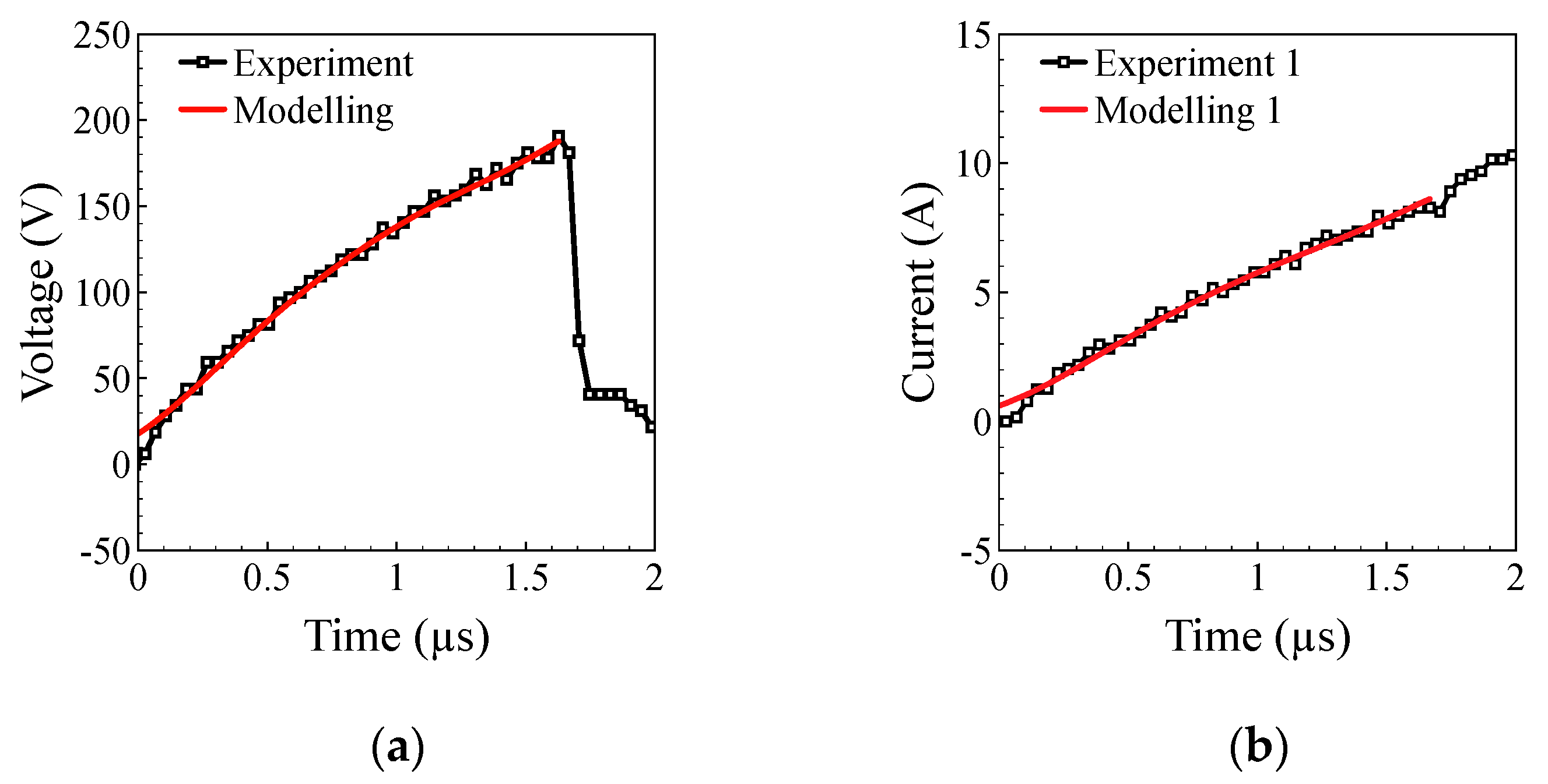
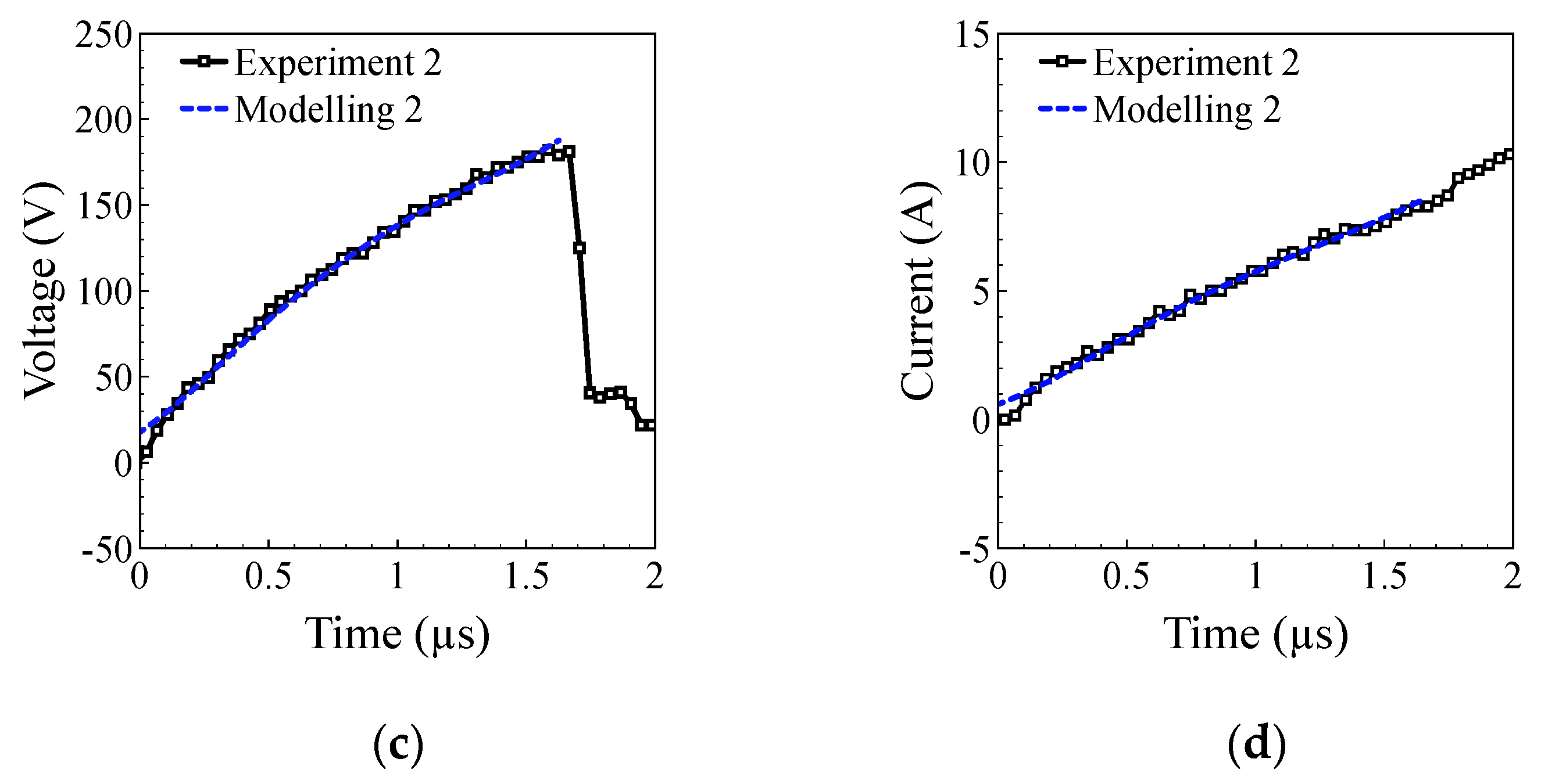
3.1. Current and Voltage Waveforms

High current during the discharge causes significant damage to the needle electrode. Observations during experiments confirmed that the migration of the micro-arc spot during the discharge caused relatively uniform erosion of the electrode material from the tip of the needle, resulting in a change of the tip shape from hemispherical (with the radius dependent on the parameters of the needle used) to relatively flat (with the area dependent on the needle angle and the length of needle remaining). Possible shapes for a needle with a 50 µm tip radius are presented in Figure 2a. Figure 2b shows the typical current and voltage waveforms for the micro-arc discharge in 10ASW operated using an original (not damaged by erosion) or damaged needle electrode, 47 nF capacitor charged to 650 V, 67 μH inductance and gap between the electrodes of 20 μm. In both cases, the discharge process can be separated into two phases: (1) A preheating phase and (2) micro-arc discharge. During the preheating phase, the voltage and current followed the same waveform of an impulse with a peak voltage of 190 V and a peak current of 8 A. During the micro-arc discharge, sustained for 5.2 µs, the voltage was almost constant at 20 V and the current further increased until the peak value of 12 A at 2.2 μs, where it turned towards decay until the termination of the micro-arc. After the termination of the positive current at 7.2 μs, the voltage and current turned to negative oscillation due to the inverse charge of the capacitor. A more detailed study of the micro-arc discharge current and voltage waveforms and ignition process can be found elsewhere [12,13,15,32].
In our previous work, it was confirmed that the bubble formation process played a key role in the generation of micro-arc discharge in seawater, therefore the variation in electrodes tip shape should have an effect on the discharge generation [32]. However, from the present experiments, as shown in Figure 2b, there was no significant difference in the current and voltage waveforms of micro-arc discharges generated using the original and the damaged needle electrode. To find out why the electrode shape did not affect the discharge, a more detailed study of the mechanism is required. Moreover, considering the possible applications of the OES spectrometry of micro-arc discharges in seawater for on-site elemental composition analysis, it is necessary to check the effect of the needle electrode’s tip shape on the measured optical emission spectra.

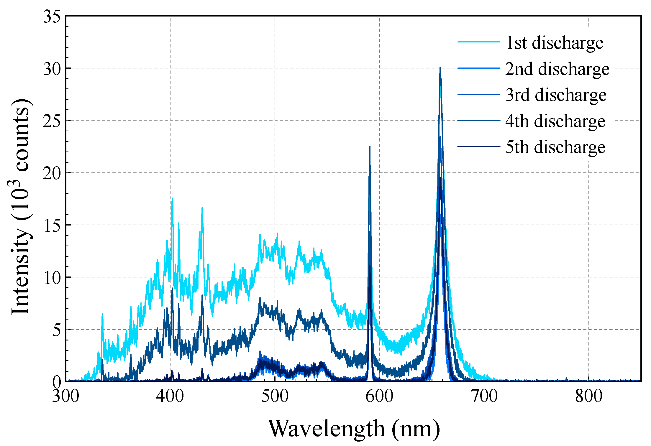
3.2. Optical Emission Spectrometry

Optical emission spectra for five consistent micro-arc discharges operated in 10ASW using W needle electrode are presented in Figure 3.
The first discharge was operated using a new needle electrode with the original hemispheric shape. After the second discharge, the tip shape had been changed due to erosion caused by the high current during the discharge. It was observed that intensity of measured optical emission for the 1st discharge was much stronger than those for the following discharges. Moreover, by repeating experiments, it was confirmed that the discharges operated using new needle electrodes always showed a strong intensity of optical emission, while the intensity varied widely after the second discharge generated using the same electrodes.
Taking into account the same experimental conditions (except for the shape of the needle electrode tip) and the same results of current and voltage waveforms, the observed instability of OES spectra intensity can be caused by damage of the needle electrode or inaccuracy in the focusing system. To confirm the effect of the focusing system on the measured spectra, OES measurements were performed with varying orientation of the lens axis. For adjusting the focusing position of the lens, a 3D micromanipulator was used. To focus the lens on the discharge gap, the spectrometer on the optical fiber was replaced with a light source. By using a micromanipulator, it was confirmed that the focusing point of the lens was completely adjusted at the center of the gap between the electrodes. The tilt angle of the optical axis varied from 10° to 0° to the plane electrode, as shown in Figure 4a,b.
Due to the variation of the observation angle, part of the gap was hidden by the needle electrode and emission from the hidden part was not collected by the lens. Moreover, due to the migration of the arc spot, optical emission collected by the lens depended on the position of the micro-arc spot for each discharge. In the case of the original needle shape, there was a smaller area hidden by the needle owing to the hemispherical shape of the needle tip, resulting in collection of emissions from a bigger area of the gap and stronger intensity of the recorded spectra. Using of a new needle electrode for each measurement can solve the problem of unstable intensity; however, it means OES measurements of micro-arc discharges are not applicable for on-site analysis, owing to the necessity of changing the needle electrode after every discharge.
The problem with the observation of the discharge gap can be partially solved by mounting the lens so as to make the lens axis parallel to the plate electrode, as presented in Figure 4b. In that case, it was possible to reduce the area hidden by the electrode and perform more reproducible OES measurements. Optical emission spectra measured using a lens mounted parallel to the plate electrode are presented in Figure 4c.
It can be noted that, in this case, the intensity of the measured optical emission and observed peaks were much more reproducible compared to the case with a tilted lens. Moreover, there was no significant difference between the measured spectrum for the first discharge generated using a new needle electrode and the spectrum for the following discharges using the damaged needle electrode. The reproducibility of OES measurements allows for a reduction in the noise level and improves the quality of the spectra by averaging the spectra of several discharges. An example of a spectrum obtained by averaging five discharges is presented in Figure 4c, as the plot of “5 discharges avg”. Averaging of spectra allows us to reduce the noise level and makes possible the accurate assignment of emission peaks for materials present in seawater and electrodes (e.g., H, O, Na, and W) in the same way as was reported elsewhere [13].
However, due to some instability in the arc discharge duration, there were still small variations in the measured spectra intensity; for example, the intensity of the fourth discharge is smaller compared to the spectra for other discharges presented in Figure 4c.

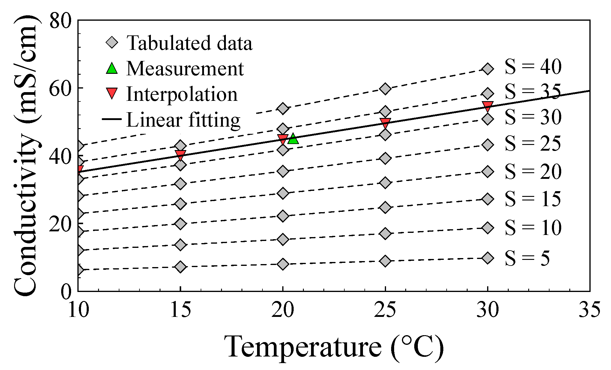
3.3. Mathematical Model

To analyze the effect of the shape of the needle electrode’s tip on the preheating phase and to confirm the results observed in the experiments, a simple mathematical model was developed using Matlab (Version 9.0; MathWorks, Natick, MA, USA), QuickField (Tera Analysis Ltd., Svendborg, Denmark), and COMSOL Multiphysics (Version 5.2a, complete set of Electromagnetics, Liquid Flow & Heat Transfer and Structural Mechanics and Acoustics modules, Material Library, and LiveLink™ for MATLAB®; COMSOL Inc., Burlington, MA, USA) software. For mathematical modeling of the preheating phase, two geometries of the needle electrode tip were used: The original hemispheric shape and a flat face of 100 µm in diameter after damage, as indicated in Figure 2a. Electrolysis was not considered in the model.
The model was divided into two blocks:
LCR oscillation model with defined steps in time, with variable resistor instead of electrodes immersed in the 10ASW;
Local process in the discharge gap and surrounding seawater using parameters calculated in the first block and dimensions from the experimental setup.
In the first block, current and voltage waveforms were calculated using common equations for LCR oscillation in Matlab software (Version 9.0; MathWorks, Natick, MA, USA). To perform the calculation, electrodes introduced into the liquid were replaced with a resistor of a value equal to the resistance of water between the electrodes. The resistance between the electrodes could depend on the geometry of electrodes and the conductivity of liquid, and therefore should be estimated in the second block of the model or measured experimentally. A simple way to calculate the current and voltage waveforms is to use a system of equations (Equations (1)–(4)) and make a small increment of time starting from the initial conditions:
I i + 1 = I i + V L i × Δ t L ,
V C i + 1 = V C i I i × Δ t C ,
V R i + 1 = I i + 1 × R i ,
V L i + 1 = V C i + 1 V R i + 1 ,
where i is the number of steps in time, I i is the current through the circuit at step i, V L i is the voltage on the inductor at step i, V C i is the voltage on the capacitor at step i, V R i is the voltage applied to the electrodes at step i, Ri is the resistance of water between the electrodes for step i from the second block of the model, C is capacitance, L is inductance, and Δ t is the increment in time. In the present work, the increment of time Δ t was set to 50 ns. The value of Δ t could be further decreased; however, it will increase the calculation time and will not result in a noticeable increase in the accuracy of the calculation. The initial conditions (step i = 0) are: I 0 = 0 , V L 0 = V C 0 ; parameters R 0 , L and C are taken from the experimental conditions and V C 0 is the voltage on the charged capacitor before the start of the discharge. In order to obtain a good correlation between the mathematical model and the experimental results, real values of L and C should be measured for the electronic components used in the circuit.
In the second block of the model, the electric field, current density, and temperature distribution in the discharge gap were calculated using COMSOL Multiphysics (version 5.2a; COMSOL Inc., Burlington, MA, USA) finite element modeling software, with the voltage applied to the electrodes as the dependent variable. In the geometry block of COMSOL Multiphysics, a 3D model was built that included the plate electrode, seawater, and needle electrode with various shapes of the tip. To reduce the number of elements in the mesh and the time required for the calculation, the volume of liquid in the model was reduced. The depth of the liquid was set to be the same as in the experimental setup (2 mm; concaving of the liquid surface was not considered in the model); however, the horizontal dimensions were reduced from 18 × 18 mm to 4 × 4 mm. It was confirmed that the reduction of volume of the liquid did not have a noticeable effect on the calculation. The 3D model was discretized using a free tetrahedral physics-controlled mesh with normal element size. The initial temperature of all components was 293.15 K and temperature of outer boundaries of water was fixed. Voltage was applied to the needle electrode when the plate electrode was grounded. Most of the material properties used in the finite element simulations are available in the materials library in COMSOL and the thermal and electrical properties of the materials used (specific heat, thermal conductivity, density, dielectric constant, etc.) are not temperature-dependent. On the other hand, one of the most important parameters of seawater for generation of the discharge is the electrical conductivity, which is temperature-dependent. For that reason, the conductivity of the liquid at each point of the mesh was adjusted according to the local temperature. There are many studies of the effect of temperature on the conductivity of natural seawater in the “Neptunian” range (temperatures of −2 to 35 °C and absolute salinities of 2 to 42 g/kg) commonly used in oceanography; however, information about the conductivity of seawater as a function of temperature for temperatures higher than 30 °C is limited [37,38,39,40]. The conductivity of 10ASW used in the present experiments was 45.1 mS/cm for a temperature of 20.5 °C; therefore, using linear interpolation of data tabulated elsewhere [37], it was found that the value of conductivity of 10ASW is equal to the value of conductivity of natural seawater with an absolute salinity of 32.35 g/kg. The values of conductivity of 10ASW for other temperatures in the “Neptunian” range were estimated using linear interpolation of tabulated data. The dependency of the conductivity of seawater on the temperature in the “Neptunian” range is reasonably well represented by a linear equation; moreover, it was confirmed elsewhere that the conductivity of seawater for higher temperatures could be estimated using a linear equation with an acceptable level of error (below 2%) [40]. Therefore, values of conductivity obtained from interpolation were fitted with a linear function, as shown in Figure 5, which allowed us to estimate the conductivity of 10ASW for temperatures above 30 °C.
Parameters of 10ASW missing from COMSOL material libraries were estimated from tabulated data as for natural seawater with absolute salinity of 32.35 g/kg [37]. The actual salinity of 10ASW as the mass fraction of inorganic solute was 33.3 g/kg from Table 1, when the salinity of natural seawater with equal conductivity was 32.35 g/kg, which was caused by some differences in composition of 10ASW and natural seawater.
The electric field distribution for step i was calculated using the voltage applied to the electrodes, which was calculated in the previous step, i − 1 ( V R i ), in the first block of the model. Examples of the calculated electric field distributions for original and damaged needle electrodes are presented in Figure 6a,b, respectively.
It can be noted that the change of shape of the needle electrode tip causes a significant difference in the electric field distribution in the discharge gap; however, electric field distribution in the surrounding liquid can be considered the same for both shapes. Furthermore, the current density and temperature profile were calculated using electric field distribution and the conductivity value of the liquid was calculated at each point of the mesh as a function of temperature, considering heat transfer. Examples of temperature profiles calculated for original and damaged needle electrodes are presented in Figure 6c,d, respectively. The effect of the shape of the needle electrode tip on the temperature profile is similar to the effect on the electric field distribution. The difference between a hemispheric shaped and a flat needle electrode tip can be observed only in the discharge gap. An insignificant difference between the electric field and temperature profiles can be noted owing to the thermal transfer in the seawater and the electrodes.
Finally, the resistivity of the water between the electrodes was calculated using the obtained values for conductivity and used in the next step of the LCR oscillation calculation.

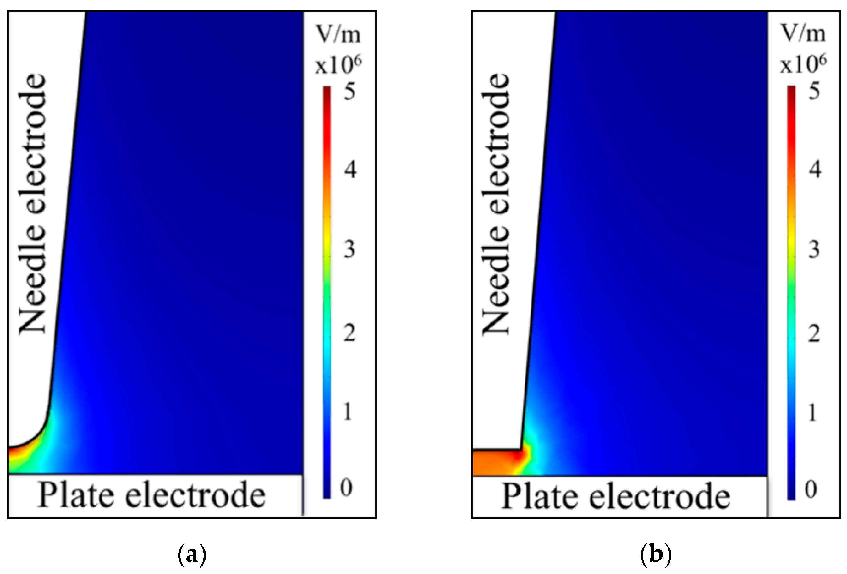
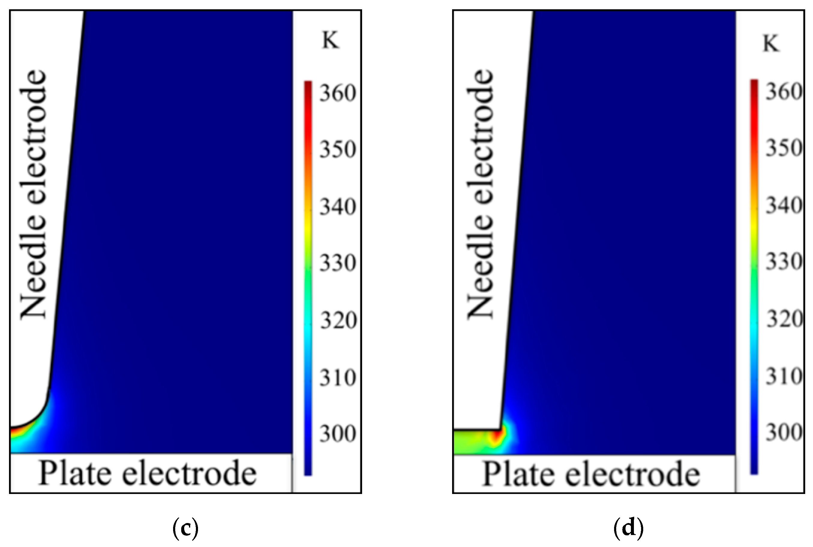
3.4. Results of Mathematical Modeling

The current and voltage waveforms during the preheating phase using original hemispheric and flat needle electrodes, calculated by a mathematical model and measured experimentally, are presented in Figure 7.
A very good agreement between the current and voltage waveforms for the preheating phase was obtained from mathematical modeling and experimental which can be observed in both cases with use of the original hemispheric needle (Figure 7a,b) and of a damaged flat needle (Figure 7c,d) electrodes. Moreover, it can be observed that there was no significant difference in the current and voltage waveforms during the preheating phase for original and damaged needle electrodes. The observed effect was caused by the high conductivity of seawater. Due to the high conductivity of seawater, significant current passed through the surrounding water, which did not participate in the plasma generation process. The influence of the needle electrode’s tip shape on the local processes in the discharge gap, which was observed in the modeling results, did not have any notable effect on the current and voltage waveforms because most of the current was passing through the surrounding liquid. Similar results were observed in the experiments as shown in Figure 2b, where no significant effect of the tip shape on current and voltage waveforms appeared during the preheating phase. Moreover, it was found by a manual change of value of the thermal conductivity of the liquid that the heat transfer did not have any noticeable effect on the total value of resistivity of liquid between the electrodes, resulting only in insignificant changes in the temperature of the liquid in the discharge gap, which could be explained by a large value of specific heat of water and the short duration of the preheating phase.
In the present experiments and the modeling results described above, the length of the part of the needle electrode immersed in liquid was about 2 mm, resulting in a large value of current passing through the bulk liquid. However, as was reported elsewhere, some changes in the resistivity of water between the electrodes were observed during the preheating phase after the insulation of the side walls of the electrodes (resulting in the length of the open part of the needle electrode being less than 1 mm), owing to a reduction in the current passing through the bulk liquid, when in the case of a 2 mm long needle the electrode resistivity was constant [32]. Taking into account the constant value of resistivity observed in the model, the preheating phase of microarc discharge in seawater could be calculated with reasonably good accuracy using only a simple LCR oscillation model with a resistor instead of electrodes immersed in liquid for a length of the needle electrode’s part immersed in liquid of 2 mm or longer.
Considering the good correlation of the experimental data and the modeling results, it can be concluded that the shape of the tip of the needle electrode only affects local processes in the discharge gap and has no significant influence on the current and voltage waveforms during the preheating phase in the case of a long needle electrode. That effect allows us to reuse needle electrodes damaged by erosion for generation of micro-arc discharges, which can be essential for conducting on-site diagnostics in deep sea owing to the possibility of carrying out measurements without replacement of the electrodes. However, the usage of damaged needle electrodes introduces strict requirements on the focusing system, requiring the adjustment of the length of the discharge gap before each discharge and electrodes long enough to compensate for local processes in the discharge gap.

4. Conclusions

Micro-arc discharges were reproducibly operated in the 10ASW using a needle-to-plane electrode system using needle electrodes with various tip shapes. A mathematical model of the preheating phase was developed for the investigation of the effect of the shape of the needle electrode’s tip on the preheating phase. From the results of the simulation, it has been confirmed that the shape of the tip only affected local processes in the discharge gap and had no effect on the current and voltage waveforms during the preheating phase for a needle electrode of 2 mm in length. Moreover, it was found that the preheating phase of the discharge could be simulated using simple LCR oscillation with a resistor instead of electrodes immersed in the liquid in the case of a needle electrode long enough to compensate for local processes in the discharge gap. It was also confirmed that there was no effect of the needle electrode’s tip shape on optical emission and that electrodes could be reused for the OES measurements even after damage caused by erosion. For the usage of damaged needle electrodes in spectroscopic measurements, strict adjustment of the optical axis in the focusing system and precise micro-manipulation for the adjustment of the discharge gap will be required before each discharge.

Author Contributions

V.G. conducted the experiments and measurements, analyzed the experimental results, performed simulations and wrote the paper; M.H. performed the formal analysis; M.I. performed the data curation; H.F. performed the validation, review and editing; A.H. supervised the project.

Funding

This research was funded by JSPS KAKENHI Grant Number 26600129.

Acknowledgments

The authors are grateful to Kei Okamura of Kochi University for providing 10ASW.

Conflicts of Interest

The authors declare no conflict of interest.

References

  1. Kim, H.-G.; Lee, H.; Kim, S.-J.; Kim, D.-H.; Kim, J.-S.; Kang, S.-Y.; Jung, S.-C. Synthesis of manganese nanoparticles in the liquid phase plasma. J. Nanosci. Nanotechnol. 2013, 13, 6103–6108. [Google Scholar] [CrossRef] [PubMed]
  2. Kim, S.-J.; Kim, B.H.; Chung, M.C.; Ahn, H.-G.; Kim, S.-C.; Kim, H.-G.; Jung, S.-C. The synthesis of nickel nanoparticles by liquid phase plasma processing. J. Nanosci. Nanotechnol. 2013, 13, 1997–2000. [Google Scholar] [CrossRef] [PubMed]
  3. Oh, J.-S.; Szili, E.J.; Ito, S.; Hong, S.-H.; Gaur, N.; Furuta, H.; Short, R.D.; Hatta, A. Slow molecular transport of plasma-generated reactive oxygen and nitrogen species and O2 through agarose as surrogate for tissue. Plasma Med. 2016, 5, 125–143. [Google Scholar] [CrossRef]
  4. Tung, N.H.; Chikae, M.; Ukita, Y.; Viet, P.H.; Takamura, Y. Sensing technique of silver nanoparticles as labels for immunoassay using liquid electrode plasma atomic emission spectrometry. Anal. Chem. 2012, 84, 1210–1213. [Google Scholar] [CrossRef] [PubMed]
  5. Akiyama, H. Streamer Discharges in Liquids and their Applications. lEEE Trans. Dielectr. Electr. Insul. 2000, 7, 646–653. [Google Scholar] [CrossRef]
  6. Ito, M.; Oh, J.S.; Ohta, T.; Shiratani, M.; Hori, M. Current status and future prospects of agricultural applications using atmospheric-pressure plasma technologies. Plasma Process. Polym. 2018, 15, e1700073. [Google Scholar] [CrossRef]
  7. Gamaleev, V.; Kajikawa, K.; Takeda, K.; Hiramatsu, M. Investigation of Nanographene Produced by In-Liquid Plasma for Development of Highly Durable Polymer Electrolyte Fuel Cells. C 2018, 4, 65. [Google Scholar] [CrossRef]
  8. Iwata, N.; Gamaleev, V.; Hashizume, H.; Oh, J.; Ohta, T.; Ishikawa, K.; Hori, M.; Ito, M. Simultaneous achievement of antimicrobial property and plant growth promotion using plasma-activated benzoic compound solution. Plasma Process. Polym. 2019, e1900023. [Google Scholar] [CrossRef]
  9. Iwata, N.; Gamaleev, V.; Oh, J.-S.; Ohta, T.; Hori, M.; Ito, M. Investigation on the long-term bactericidal effect and chemical composition of radical-activated water. Plasma Process. Polym. 2019, e1900055. [Google Scholar] [CrossRef]
  10. Kohara, Y.; Terui, Y.; Ichikawa, M.; Yamamoto, K.; Shirasaki, T.; Kohda, K.; Yamamoto, T.; Takamura, Y. Atomic emission spectrometry in liquid electrode plasma using an hourglass microchannel. J. Anal. At. Spectrom. 2015, 30, 2125–2128. [Google Scholar] [CrossRef]
  11. Kohara, Y.; Terui, Y.; Ichikawa, M.; Shirasaki, T.; Yamamoto, K.; Yamamoto, T.; Takamura, Y. Characteristics of liquid electrode plasma for atomic emission spectrometry. J. Anal. At. Spectrom. 2012, 27, 1457. [Google Scholar] [CrossRef]
  12. Gamaleev, V.; Okamura, Y.; Kitamura, K.; Hashimoto, Y.; Oh, J.-S.; Furuta, H.; Hatta, A. Investigation of microplasma discharge in sea water for optical emission spectroscopy. Jpn. J. Appl. Phys. 2016, 55, 07LC03. [Google Scholar] [CrossRef]
  13. Gamaleev, V.; Furuta, H.; Hatta, A. Atomic Emission Spectroscopy of Microarc Discharge in Sea Water for On-Site Detection of Metals. IEEE Trans. Plasma Sci. 2019, 47, 1841–1850. [Google Scholar] [CrossRef]
  14. Van Khoai, D.; Miyahara, H.; Yamamoto, T.; Tue, P.T.; Okino, A.; Takamura, Y. Development of AC-driven liquid electrode plasma for sensitive detection of metals. Jpn. J. Appl. Phys. 2016, 55, 02BC23. [Google Scholar] [CrossRef]
  15. Gamaleev, V.; Furuta, H.; Hatta, A. Generation of micro-arc discharge plasma in highly pressurized seawater. Appl. Phys. Lett. 2018, 113, 214102. [Google Scholar] [CrossRef]
  16. Seepersad, Y.; Pekker, M.; Shneider, M.N.; Fridman, A.; Dobrynin, D. Investigation of positive and negative modes of nanosecond pulsed discharge in water and electrostriction model of initiation. J. Phys. D Appl. Phys. 2013, 46, 355201. [Google Scholar] [CrossRef] [Green Version]
  17. Schoenbach, K.; Kolb, J.; Xiao, S.; Katsuki, S.; Minamitani, Y.; Joshi, R. Electrical breakdown of water in microgaps. Plasma Sources Sci. Technol. 2008, 17, 024010. [Google Scholar] [CrossRef]
  18. Jin, Y.; Cho, C.; Ryoo, H.; Kim, J.; Rim, G. Long Gap Discharge in Water. J. Korean Phys. Soc. 2011, 59, 3640–3643. [Google Scholar] [CrossRef]
  19. Vetchinin, S.P.; Vasilyak, L.M.; Pecherkin, V.Y.; Panov, V.A.; Son, E.E. Spark discharge in conductive liquid with microbubbles. J. Phys. Conf. Ser. 2016, 774, 012183. [Google Scholar] [CrossRef] [Green Version]
  20. Gavrilov, I.M.; Kukhta, V.R.; Lopatin, V.V.; Petrov, P.G. Dynamics of prebreakdown phenomena in a uniform field in water. IEEE Trans. Dielectr. Electr. Insul. 1994, 1, 496–502. [Google Scholar] [CrossRef]
  21. An, W.; Baumung, K.; Bluhm, H. Underwater streamer propagation analyzed from detailed measurements of pressure release. J. Appl. Phys. 2007, 101, 053302. [Google Scholar] [CrossRef]
  22. Devins, J.C.; Rzad, S.J.; Schwabe, R.J. Breakdown and prebreakdown phenomena in liquids. J. Appl. Phys. 1981, 52, 4531–4545. [Google Scholar] [CrossRef]
  23. Kitano, A.; Iiduka, A.; Yamamoto, T.; Ukita, Y.; Tamiya, E.; Takamura, Y. Highly sensitive elemental analysis for Cd and Pb by liquid electrode plasma atomic emission spectrometry with quartz glass chip and sample flow. Anal. Chem. 2011, 83, 9424–9430. [Google Scholar] [CrossRef] [PubMed]
  24. Gamaleev, V.; Furuta, H.; Hatta, A. Detection of metal contaminants in seawater by spectral analysis of microarc discharge. Jpn. J. Appl. Phys. 2018, 57, 0102B8. [Google Scholar] [CrossRef]
  25. Khoai, D.V.; Yamamoto, T.; Ukita, Y.; Takamura, Y. On-chip solid phase extraction-liquid electrode plasma atomic emission spectrometry for detection of trace lead. Jpn. J. Appl. Phys. 2014, 53, 05FS01. [Google Scholar] [CrossRef]
  26. Wilson, C.G.; Gianchandani, Y.B. Spectral detection of metal contaminants in water using an on-chip microglow discharge. IEEE Trans. Electron Devices 2002, 49, 2317–2322. [Google Scholar] [CrossRef]
  27. Raizer, Y.P. Gas Discharge Physics, 1st ed.; Allen, J.E., Ed.; Springer: Berlin/Heidelberg, Germany, 1991; ISBN 978-3-642-64760-4. [Google Scholar]
  28. Lu, Q.; Yang, S.; Sun, D.; Zheng, J.; Li, Y.; Yu, J.; Su, M. Direct determination of Cu by liquid cathode glow discharge-atomic emission spectrometry. Spectrochim. Acta Part B At. Spectrosc. 2016, 125, 136–139. [Google Scholar] [CrossRef]
  29. Bostrom, K.; Kunzendorf, H. Marine Mineral Exploration. Elsevier Oceanogr. Ser. 1986, 41, 21–53. [Google Scholar] [CrossRef]
  30. Glasby, G.P. Deep Seabed Mining: Past Failures and Future Prospects. Mar. Georesources Geotechnol. 2002, 20, 161–176. [Google Scholar] [CrossRef]
  31. Bruneton, P. Geological environment of the Cigar Lake uranium deposit. Can. J. Earth Sci. 1993, 30, 653–673. [Google Scholar] [CrossRef]
  32. Gamaleev, V.; Oh, J.; Furuta, H.; Hatta, A. Investigation of Effect of Needle Electrode Configuration on Microplasma Discharge Process in Sea Water. IEEE Trans. Plasma Sci. 2017, 45, 754–760. [Google Scholar] [CrossRef]
  33. Jones, H.M.; Kunhardt, E.E. The influence of pressure and conductivity on the pulsed breakdown of water. IEEE Trans. Dielectr. Electr. Insul. 1994, 1, 1016–1025. [Google Scholar] [CrossRef]
  34. Xiao, P.; Staack, D. Microbubble generation by microplasma in water. J. Phys. D Appl. Phys. 2014, 47, 355203. [Google Scholar] [CrossRef]
  35. Atrazhev, V.M.; Vorob’ev, V.S.; Timoshkin, I.V.; Given, M.J.; Macgregor, S.J. Mechanisms of Impulse Breakdown in Liquid: The Role of Joule Heating and Formation of Gas Cavities. IEEE Trans. Plasma Sci. 2010, 38, 2644–2651. [Google Scholar] [CrossRef]
  36. Potocký, Š.; Saito, N.; Takai, O. Needle electrode erosion in water plasma discharge. Thin Solid Films 2009, 518, 918–923. [Google Scholar] [CrossRef]
  37. Lide, D.R.; Baysinger, G. CRC Handbook of Chemistry and Physics, 83rd ed.; CRC Press: Boca Raton, FL, USA, 2002. [Google Scholar]
  38. Sauerheber, R.; Heinz, B. Temperature Effects on Conductivity of Seawater and Physiologic Saline, Mechanism and Significance. Chem. Sci. J. 2015, 6, 109. [Google Scholar] [CrossRef]
  39. Hayashi, M. Water For Environmental Monitoring and Geophysical Data Inversion. Environ. Monit. Assess. 2004, 96, 119–128. [Google Scholar] [CrossRef]
  40. Pawlowicz, R. The electrical conductivity of seawater at high temperatures and salinities. Desalin. J. 2012, 300, 32–39. [Google Scholar] [CrossRef]
Figure 1. Experimental setup.
Plasma 02 00022 g001
Figure 2. Original needle electrode geometry and damaged needle electrodes geometries with 70 µm, 100 µm and 110 µm in diameter flat surface of the tip (a) and typical current and voltage waveforms for micro-arc discharge in seawater (b).
Plasma 02 00022 g002
Figure 3. Instability of the measured optical emission spectra.
Plasma 02 00022 g003
Figure 4. Mounting of lens during measurements (a) with an angle and (b) parallel to the plate electrode; and (c) optical emission spectra measured using a lens mounted parallel to the plate electrode.
Plasma 02 00022 g004
Figure 5. Tabulated data of conductivity values of seawater with various salinity, interpolation, and linear fit of conductivity of seawater with salinity similar to 10ASW as a function of temperature.
Plasma 02 00022 g005
Figure 6. Electric field distribution for the (a) original and (b) damaged needle electrode cases; and temperature profile of seawater for the (c) original and (d) damaged needle electrode cases 1 µs after the start of the discharge.
Plasma 02 00022 g006aPlasma 02 00022 g006b
Figure 7. Experimental data and results of mathematical modeling of the preheating phase for (a) voltage applied to the electrodes and (b) current using the original needle electrode; (c) voltage applied to the electrodes; and (d) current using a damaged needle electrode.
Plasma 02 00022 g007aPlasma 02 00022 g007b
Table 1. Composition of 10ASW in grams for 1 kg of water and elemental concentration.
Composition of 10ASWElemental Concentration
IngredientMass (g)ElementConcentration (mol/kg)
NaCl23.939Cl0.549
MgCl2 + 6H2O10.849Na0.468
Na2SO43.994Mg0.055
CaCl21.123S0.028
KCl0.667Ca0.01
NaHCO30.196K0.009
KBr0.098C0.0023
H3BO30.027Br0.0008
SrCl2 + H2O0.004B0.00046
NaF0.003F0.000053

