Article

Surface Transformation of Ultrahigh-Temperature ZrB2–HfB2–SiC–CCNT Ceramics Under Exposure to Subsonic N2-CH4 Plasma Flow

by
Elizaveta P. Simonenko
1,*,
Aleksey V. Chaplygin
2,*,
Nikolay P. Simonenko
1,
Ilya V. Lukomskii
2,
Semen S. Galkin
2,
Anton S. Lysenkov
3,
Ilya A. Nagornov
1,
Artem S. Mokrushin
1,
Anatoly F. Kolesnikov
2 and
Nikolay T. Kuznetsov
1
1
Kurnakov Institute of General and Inorganic Chemistry of the Russian Academy of Sciences, Leninsky pr., 31, Moscow 119991, Russia
2
Ishlinsky Institute for Problems in Mechanics of the Russian Academy of Sciences, Vernadskogo pr., 101-1, Moscow 119526, Russia
3
A. A. Baikov Institute of Metallurgy and Materials Science, Russian Academy of Sciences, Leninsky pr., 49, Moskow 119334, Russia
*
Authors to whom correspondence should be addressed.
Ceramics 2025, 8(2), 67; https://doi.org/10.3390/ceramics8020067
Submission received: 30 April 2025 / Revised: 21 May 2025 / Accepted: 31 May 2025 / Published: 2 June 2025

Abstract

The chemical and microstructural transformation of the surface of a 31.5 vol.% ZrB2-31.5 vol.% HfB2-27 vol.% SiC-10 vol.% CCNT ultrahigh-temperature ceramic sample (where CCNT refers to carbon nanotubes) was studied under the influence of a subsonic N2-plasma flow with the addition of 5 mol% methane, simulating aerodynamic heating in the atmosphere of Titan. As in the case of pure nitrogen flow, it was found that silicon carbide is removed from the surface. Zirconium and hafnium diborides are partially transformed into a Zr-Hf-B-C-N solid solution in the experiment conducted. XRD, Raman spectroscopy, and SEM-EDX analysis show that the presence of C2 in the N2-CH4 plasma flow leads to surface carbonization (formation of a graphite- and diamond-like coating with a high proportion of amorphous carbon), resulting in significant changes in the microstructure and emissivity, potentially affecting the catalytic properties of the surface.

1. Introduction

Ceramic materials based on ZrB2-SiC or HfB2-SiC systems are recognized as promising candidates for manufacturing the most thermally loaded parts of high-speed aircraft, primarily those with low radii of curvature [1,2,3]. This phenomenon can be attributed to the favorable combination of high melting temperatures (without phase transformations over a wide temperature range) and thermal conductivity, the value of which remains relatively stable even at temperatures of up to ~2000 °C [4,5,6]. In addition, such ceramics have sufficiently high emissivity [7,8] to remove heat from areas that overheat due to sharp edges and the nose. This is achieved through increased thermal conductivity of the sharp edges and nose parts due to increased thermal conductivity and subsequent radiation from colder side surfaces [2]. Along with good mechanical properties, ceramic materials based on ZrB2(HfB2)-SiC systems have good oxidation resistance even at 2000 °C, including exposure to flows containing atomic nitrogen and oxygen [8,9,10,11], which determines the main possible field of their application.
Despite the advantageous properties of ZrB2(HfB2)-SiC ultrahigh-temperature ceramic composites, have certain characteristics, particularly fracture toughness and thermal shock resistance, which urgently require improvement. Furthermore, due to the high melting point and covalent bonding within the structure of the constituent components, achieving samples with near-full density necessitates the use of sintering additives. These additives include refractory metal silicides and nitrides [12,13,14], as well as carbon materials [15] such as graphite platelets [16,17], carbon nanotubes [18,19] and fibers [20], graphene [19,21,22,23,24,25,26,27]. For instance, in [28] it was demonstrated that the incorporation of graphite platelets enhances the overall thermal resistance of the ZrB2-20vol.%SiC-15vol.% graphite material, even in sharp-edged geometries (1.5 mm radius of curvature). Introducing an additional component can also significantly affect the degradation process of the composite material under high-velocity gas flow conditions, such as its oxidation resistance [22]. Therefore, to predict the behavior of such modified ultrahigh-temperature ceramics under aerodynamic heating, it is rational to expose them to high-speed gas flow exposure, for example, using ICP facilities [29,30].
The favorable combination of properties exhibited by ZrB2(HfB2)-SiC ultrahigh-temperature ceramics leads to the concept of their application not only in thermal protection systems for innovative, reusable spacecraft returning to Earth, but also for the exploration of other celestial bodies in the solar system [31], which have significantly different atmospheric compositions. For example, we previously investigated the behavior of (HfB2-30vol.%SiC)-1vol.%C(graphene) materials in a dissociated CO2 flow (including with additional laser heating) [24] and, for the first time, noted their potential use in atmospheres predominantly composed of carbon dioxide (Venus, Mars). It was established [24] that a multi-layered near-surface oxidation region forms under these conditions, similar to that observed under high-speed airflow exposure. Furthermore, the thickness of this region is extremely sensitive to the surface temperature. Increasing the temperature from 1750–1790 to 2000–2200 °C (over 2 min) due to additional laser heating results in an increase in the thickness of the degraded near-surface ceramic region from 165 to 380 μm.
Celestial bodies with nitrogen-based atmospheres, such as Saturn’s moon Titan, are equally intriguing [32]. The number of experimental studies dedicated to investigating ZrB2(HfB2)-SiC ultrahigh-temperature ceramic behavior in a nitrogen atmosphere is significantly higher [18,23,33,34,35] compared to that of studies modeling their behavior in a CO2 atmosphere. The experimental setup for material testing in a nitrogen flow is highly sensitive to oxygen impurities in the gas stream. This is because the instantaneous surface oxidation of these materials substantially alters the emissivity and catalytic properties, affecting the surface temperature regime. Nevertheless, our previous experiments with oxygen-free nitrogen plasma show that the phase composition and microstructure of the degraded ceramic surface based on the HfB2-SiC system differ significantly depending on whether a subsonic [36] or supersonic flow of dissociated nitrogen [23] is employed. In the former case, a hexagonal phase of low hafnium nitride Hf3N2 forms. In the latter case, a cubic solid solution Hf(C,N) is present on the surface against the background of reflections from the original HfB2 phase.
The experimental data obtained from testing ZrB2(HfB2)-SiC UHTC in pure nitrogen are extremely important for predicting their behavior in Titan’s atmosphere. However, it is important to note that the atmosphere also contains between 1.4 and 5% methane [37,38], depending on the altitude. Furthermore, comparative experiments conducted by Carandente et al. [32] on the interaction of different sample surface types with nitrogen plasma and plasma containing 80% N2 and 20% CH4 demonstrated a significant increase in heat flux in the latter case. The authors attribute this phenomenon to different reactions catalyzed by the sample surface (regardless of its emissivity), rather than to more intense radiative heating from the N2+CH4 flow. A literature review revealed a lack of information on the behavior of ultrahigh-temperature ceramics when exposed to high-enthalpy flows containing dissociated nitrogen and methane.
This study aims to investigate the thermochemical effect of a subsonic N2 plasma flow containing 5 mol% methane on the surface of UHTC with the composition ZrB2-HfB2-SiC-CCNT and to evaluate its chemical transformation.

2. Materials and Methods

2.1. Sample Preparation

The method for manufacturing the ceramic composite material 31.5 vol.% ZrB2-31.5 vol.% HfB2-27 vol.% SiC-10 vol.% CCNT is described in detail in [18]. In brief, this involved reactive hot pressing of a pre-synthesized composite powder ZrB2-HfB2-SiO2-C, obtained by the sol-gel method, at a temperature of 1800 °C (heating rate 10 °C/min, holding time at maximum temperature 30 min) and a pressure of 30 MPa in graphite dies using a hot press model HP20-3560-20 (Thermal Technology Inc., Minden, NV, USA). The relative density of the investigated sample was 108 ± 1% due to the formation of low amount of impurity phases ZrC/HfC [18].
The following reagents were utilized in the production of the composite powder: hafnium diboride (>98%, particle size 2–3 µm, aggregate size~20–60 µm, Tugoplavkie Materialy LLC., Taganrog, Russia), zirconium diboride (>98%, MP Complex LLC., Izhevsk, Russia), tetraethoxysilane (TEOS) Si(OC2H5)4 (>99.99%, EKOS-1 JSC, Moscow, Russia), LBS-1 bakelite varnish (Karbolit OJSC, Moscow, Russia), formic acid CH2O2 (>99%, Spektr-Chem LLC., Moscow, Russia), multi-walled carbon nanotubes (brand “Dealtom”, SPE “Center of Nanotechnologies”, Moscow, Russia).
High-purity gaseous nitrogen (99.999%, brand “5.0”, manufacturer LLC. “BK Group”, Moscow, Russia) and methane (99.99%, brand “4.0”, manufacturer LLC. “BK Group”, Moscow, Russia) were utilized to perform the experiment investigating the effects of a subsonic N2-CH4 plasma flow on the ceramic samples.

2.2. Test Facility

The effects of subsonic high-enthalpy nitrogen jets containing 5 mol% methane (corresponding to its maximum concentration in Titan’s atmosphere) on a ZrB2-HfB2-SiC-CCNT ultrahigh-temperature ceramic sample were studied using a 100 kW high-frequency induction plasmatron VGU-4 [39,40]. The distance between the nozzle exit and the sample was 30 mm. The mass flow rate of the N2+CH4 gas mixture was 2.4 g/s (controlled by a Bronkhorst MV-306 mass flow meter, Bronkhorst High-Tech B.V., Ruurlo, Netherlands), and the pressure inside the test chamber was (8.1 ± 0.1)⋅103 Pa. The sample was immersed in the high-enthalpy jet at a plasmatron anode power (N) of 45.0 ± 0.1 kW and maintained under these conditions for 10 min (600 s). The 15 mm diameter cylindrical sample was pre-installed by friction in a water-cooled socket flush with the front surface, and the gap was filled with flexible SiC and carbon-felt-based thermal insulation to minimize heat losses. After the test, the chamber was backfilled with nitrogen to cool the sample to a temperature < 300 °C.
The surface temperature of the heated sample in the central region (with a viewing area diameter of ~5 mm) was measured using a Mikron M700S spectral-ratio pyrometer (Mikron Infrared Inc., Oakland, CA, USA), with a working temperature range of 1000–3000 °C. The temperature distribution across the sample surface was studied using a Tandem VS-415U thermal imager (OOO «PK ELGORA», Korolev, Moscow region, Russia). Thermal imaging was performed with the spectral emissivity ελ set to 0.6 at a wavelength of 0.9 μm since the experiment assumed a change in ελ. The correction of the central region temperatures, measured with the thermal imager, to the color temperature measured with the spectral-ratio pyrometer allowed us to estimate the spectral emissivity values and their change during the experiment.
The technique for determining the reference heat flux to the cold, highly catalytic copper surface is described in detail in [41]. The measurements performed yielded a heat flux value of 315 W/cm2 for the operating regime and gas flow composition used.
The emission spectra of free N2 and N2+CH4 plasma jets were collected using a high-resolution HR4000 spectrometer (Ocean Optics, Orlando, FL, USA) with a spectral range of 200–1050 nm (Figure 1). The experimental procedure and equipment design are described in more detail in [42]. As can be seen, the emission intensity of the N2+CH4 mixture flow significantly exceeds that of a subsonic flow of pure nitrogen (with fixed process parameters), which is also noticeable in the corresponding photographs due to CN luminescence [32]. For the pure N2 plasma flow (Figure 1b), the presence of N2, N2+, and atomic nitrogen was observed, as noted previously in [42], where it was also noted that no oxygen impurities were detected.
The emission spectrum of the N2 flow containing 5 mol% CH4 (Figure 1a) is dominated by the CN violet band system [43], with the CN red bands (whose intensity increases with increasing pressure in the plasmatron test chamber [44]), and C2 bands also appearing, as has been observed for N2-CH4 plasma in the literature, which is related to N2+CH4 plasma, including that produced using ICP facilities [45,46,47].

2.3. Materials’ Investigation

XRD patterns of the synthesized samples were acquired using a Bruker D8 Advance X-ray diffractometer (Bruker, Billerica, MA, USA), employing CuKα radiation with a resolution of 0.02° and a signal accumulation time of 0.3 s per point. Phase analysis was performed using the MATCH! software (Version 3.8.1.143). Identification of crystalline phases was carried out with the Phase Identification from Powder Diffraction software, Version 3.8.0.137 (Crystal Impact, D-53227 Bonn, Germany), which utilizes the Crystallography Open Database (COD).
Raman spectra of the sample surface before and after the exposure were acquired using a SOL Instruments Confotec NR500 Raman spectrometer (objective 40×, 532 nm laser). The lattice: 600, signal accumulation time was 30 s.
The surface and fracture microstructure of the ceramic sample after exposure to a subsonic N2+5 mol% CH4 plasma flow was investigated using a FIB-SEM TESCAN AMBER double-beam scanning electron-ion microscope (Tescan s.r.o., Brno-Kohoutovice, Czech Republic), with an accelerating voltage of 2, 5 and 20 kV.

3. Results and Discussion

3.1. Exposure of the ZrB2-HfB2-SiC-CCNT Sample Surface to a Subsonic N2+CH4 Plasma Flow

After the sample was immersed in the dissociated nitrogen jet containing 5 mol% methane, a rapid increase in its surface temperature was observed (Figure 2), reaching 2115 °C after the first minute of exposure. Subsequently, the heating rate decreased significantly to ~0.2 °C/min, and a maximum temperature of 2229 °C was recorded just before the end of the exposure. Analysis of the thermal images obtained during the experiment (Figure 3) revealed that, despite the measures taken to insulate the sample from the water-cooled model, contact between the sample and the cold wall was unavoidable, potentially leading to some heat loss. During the heating process, a significant temperature difference of approximately 150–200 °C was observed between the central and peripheral regions. This temperature difference stabilized at this level after the fourth minute of exposure. The even greater temperature difference observed in the thermal images and corresponding temperature distributions along the sample diameter is likely due to contact with the water-cooled model wall, causing localized cooling. The maximum recorded temperatures were observed in the central region of the sample, reaching 2270–2275 °C, while the peripheral regions reached a temperature of at least 2060–2085 °C after 300 s of exposure.
After the heating was switched off, the sample remained in a flow of cold nitrogen until the surface temperature dropped below 300 °C. The mass loss of the sample after exposure was 0.2%, and the ablation rate was 4.0 × 10⁻⁴ g·cm–2·min–1.

3.2. Investigation of the Surface and Fracture of a ZrB2-HfB2-SiC-CCNT Sample After Exposure to a Subsonic N2+CH4 Flow

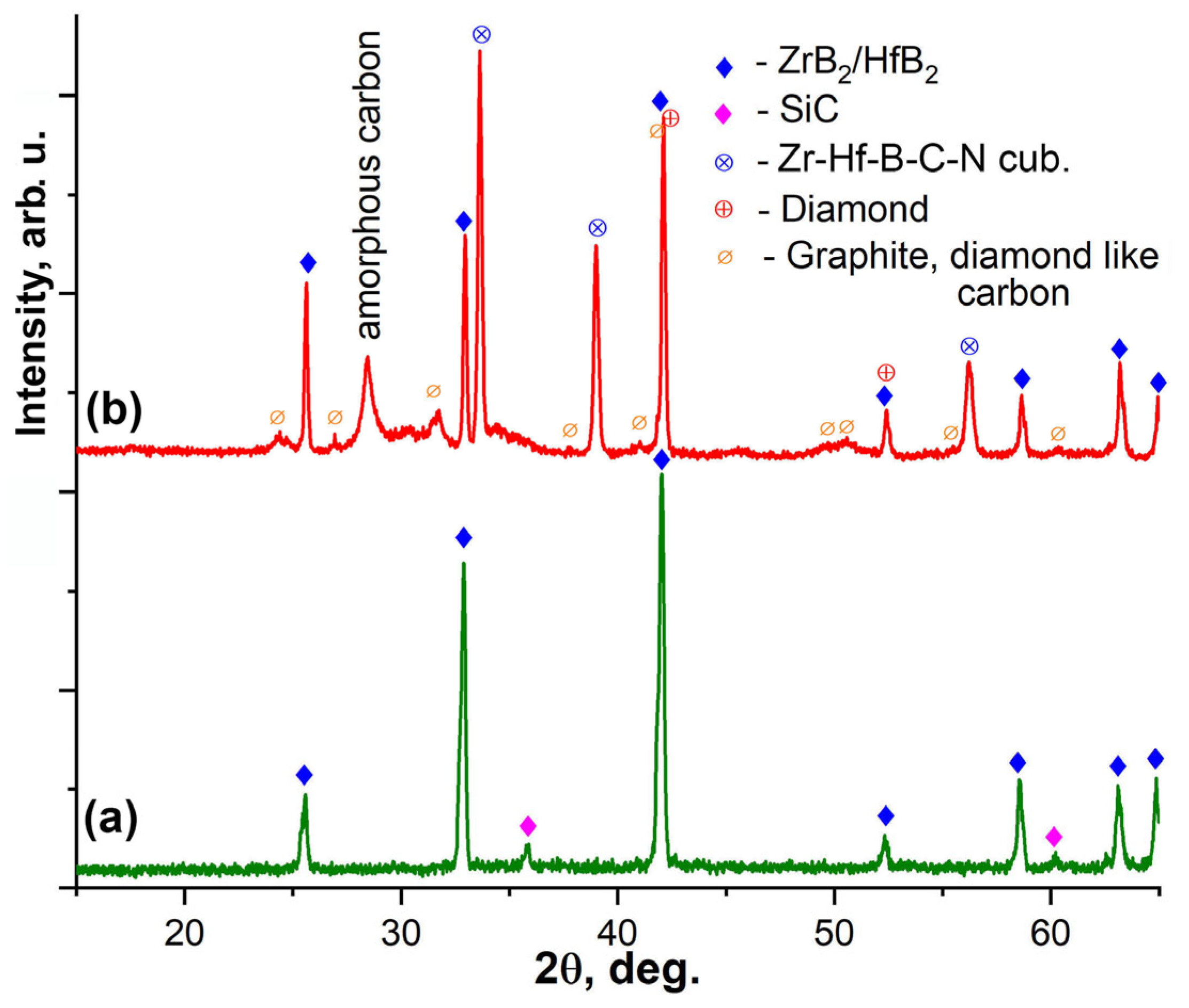
The X-ray diffraction analysis of the ZrB2-HfB2-SiC-CCNT sample surface after exposure (Figure 4) revealed significant changes consistent with the occurring reactions. The initial sample primarily consisted of a ZrB2-HfB2 solid solution [48,49] with the presence of cubic silicon carbide [50]. However, after thermochemical treatment, the cubic phase of a complex composition based on zirconium and hafnium monoborides Zr(Hf)B [51,52] became the dominant phase on the surface (while retaining the reflections of the ZrB2-HfB2 phase). This is likely due to the incorporation of carbon and nitrogen atoms into its lattice, leading to the formation of a cubic phase of complex composition in the Zr-Hf-B-C-N system [52,53,54]. Furthermore, the SiC phase disappeared, and additional low-intensity reflections appeared, which could be attributed to various carbon modifications (amorphous carbon [55,56], graphite [57], diamond- and graphite-like phases [58,59]), likely formed due to the addition of 5 mol% methane to the nitrogen plasma.
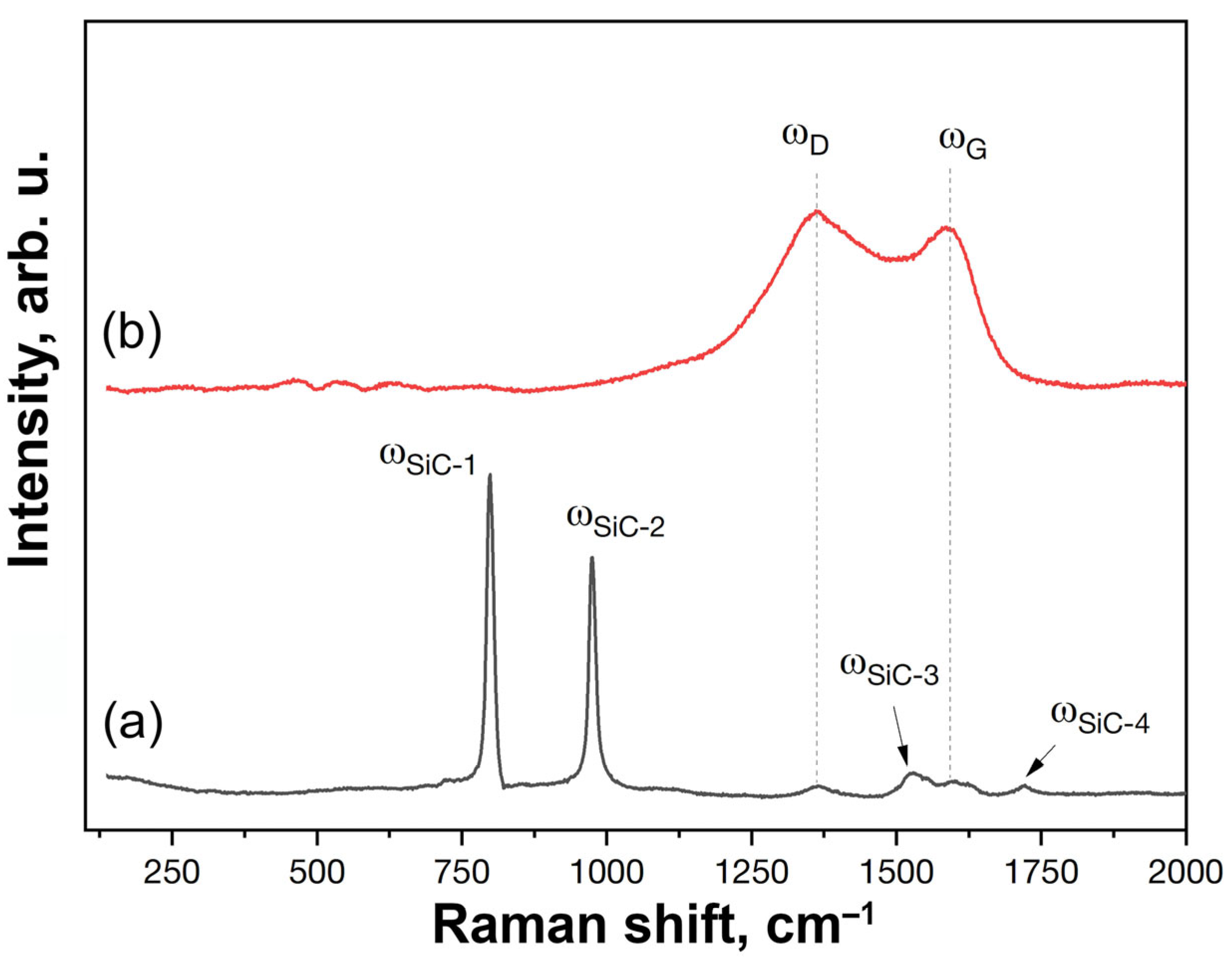
The formation of surface carbon layers (including a diamond-like coating) on the ceramic surface is further supported by the Raman spectroscopy data, as shown in Figure 5. The spectrum of the initial sample exhibits two prominent, intense peaks, ωSiC-1 and ωSiC-2, at 799 and 975 cm−1, which correspond well with silicon carbide [60]. In the lower wavenumber region, low-intensity carbon bands ωD and ωG are present at 1365 and 1591 cm−1, as well as broadened second-order modes of silicon carbide, ωSiC-3 and ωSiC-4, at 1522 and 1721 cm−1 [61]. The phases of the ZrB2-HfB2 and Zr-Hf-B-C-N solid solutions, which were detected by XRD, do not have characteristic intense Raman modes and, therefore, did not appear in the obtained Raman spectra (Figure 5, spectrum 1). The relatively low-intensity D-and G-bands are most likely due to the presence of carbon nanotubes. It is worth noting that for the initial sample, the intensity of the G-band is higher than that of the D-band, which is characteristic of carbon nanotubes [62].
The Raman spectrum of the ZrB2-HfB2-SiC-CCNT sample surface after the tests significantly differs from the initial one (Figure 5, spectrum 2). The characteristic silicon carbide bands are no longer present, which is consistent with the XRD data (Figure 4), and only broadened and intense carbon D- and G-bands at 1365 and 1591 cm−1 are observed. Comparing the D- and G-bands before and after the tests reveals that they differ significantly in shape and intensity, which may indicate the formation of carbon nanostructures of a different modification. After the thermochemical treatment, the D-band becomes more intense than the G-band. Typically, the D-band is associated with diamond-like materials, and the G-band with graphite-like materials, and the intensity of these bands can be used to infer the chemical nature of the resulting materials, which together constitute a broad group of various carbon structures [63]. According to XRD data, it can be concluded that a layer containing both amorphous and diamond-like carbon (DLC) formed on the sample surface. For amorphous carbon, a broadened G-band is usually observed [63], while for DLC structures, the appearance of an intense D-band is characteristic [64]. However, the data presented in the literature vary widely, and in some studies, authors present Raman spectra for DLC in which the G-band is more intense than the D-band [65]. In the present work, the combined Raman spectroscopy and XRD data indicate the formation of a carbon layer on the surface, containing both amorphous carbon and diamond-like layers.
Scanning electron microscopy (SEM) analysis of the surface microstructure (Figure 6) revealed the formation of hierarchically organized, faceted structures with an ordered, stepped structure of trigonal aggregates under the action of the N2+CH4 plasma. The average step width ranges from 50 to 90 nm (up to 165 nm). It is likely that the high-enthalpy jet containing C2 (Figure 1) induces the ordered growth of diamond- and graphite-like films [66], which is possible not only in the “methane-inert gas” gas mixture, but also in the N2-CH4 mixture [67,68] even without the addition of H2 [69], including model experiments simulating the effects of the Titan atmosphere [70]. This is also supported by the surface distribution data of Zr, Hf, and C (as is well known, energy-dispersive X-ray spectroscopy data for carbon and other light elements must be interpreted with caution due to the low energy of the emitted radiation), as shown in Figure 7 and EDX analysis. As can be seen, carbon distribution generally corresponds to the surface microstructure, and the ratio n(C):n(Zr+Hf) is ~1.9, which, along with the Raman spectroscopy data, allows us to cautiously suggest an increased carbonization of the sample surface exposed to nitrogen plasma with the addition of 5 mol% methane. It should be noted that the mutual distribution of zirconium and hafnium on the transformed surface indicates not only the formation of hexagonal (Zr,Hf)B2 and cubic (Zr,Hf)(B,C,N) solid solutions, but also the partial preservation of the cores with a predominant content of ZrB2, which is characteristic of the original composite material [18]. The complete absence of silicon on the ceramic surface, which was also observed after exposure to N2-plasma without the addition of methane [18,23,35,36], can be explained by its evaporation from the SiC composition under the influence of temperatures of 2100–2200 °C and reduced pressure, as well as by the reactions occurring on the surface to form volatile products.
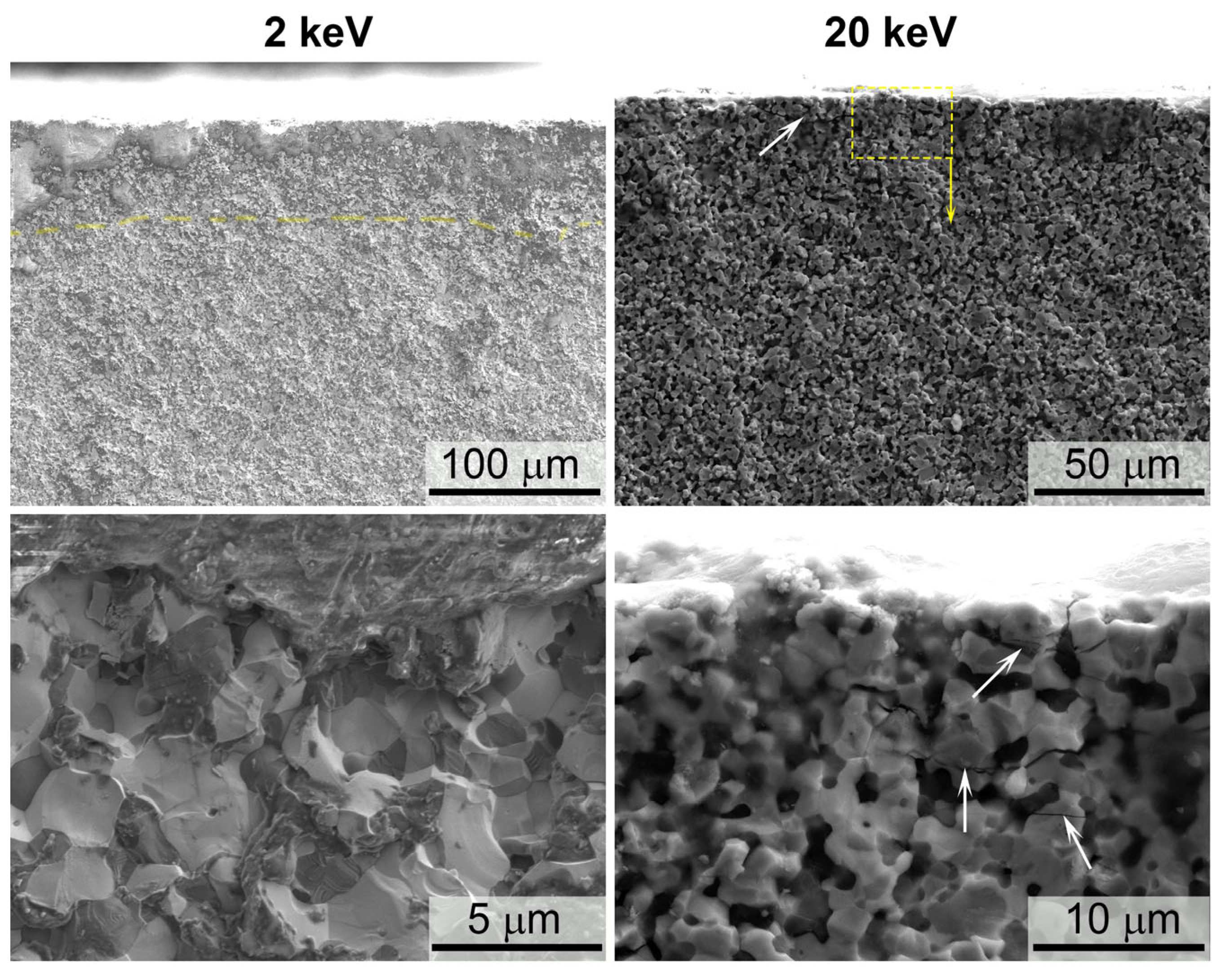
The investigation of the ceramic material’s degradation depth was also conducted using SEM coupled with EDX analysis—Figure 8, Figure 9 and Figure 10. The study of the sample’s fracture after thermochemical treatment at two accelerating voltages of 2 and 20 kV (Figure 8) revealed significant changes in the sample’s fracture microstructure up to a depth of ~40–60 μm: large non-crystalline inclusions are present, likely a light phase, since the granular structure of di- and monoborides of zirconium-hafnium appears in their localization upon increasing the accelerating voltage from 2 to 20 kV.
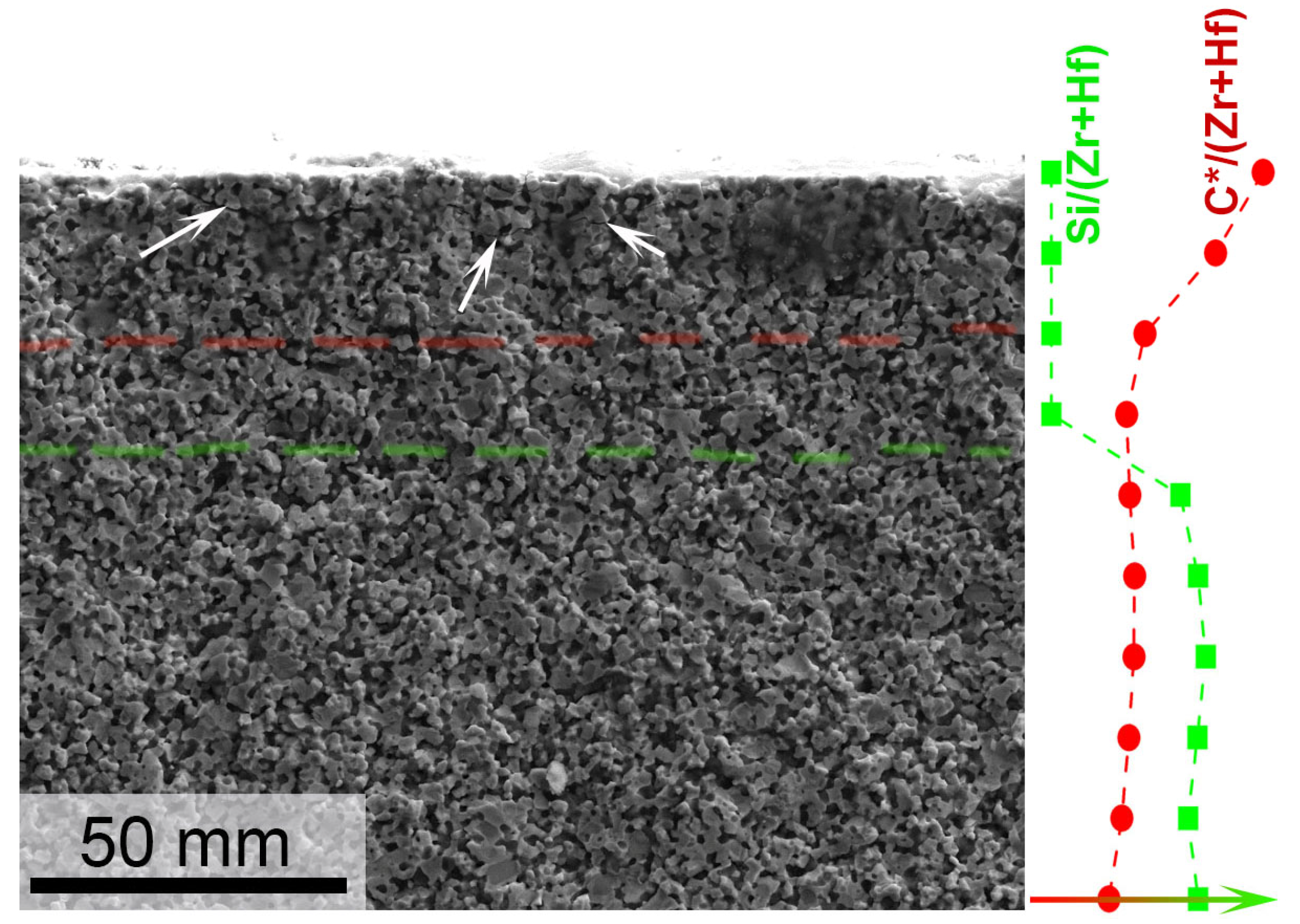
Furthermore, horizontal cracks are clearly visible in the micrographs obtained at a high accelerating voltage (Figure 8 and Figure 9, indicated by arrows), mainly within the near-surface layer with a thickness of ~15 μm. In Figure 9, EDX analysis data (molar ratios of Si/(Zr+Hf) and C/(Zr+Hf) as a function of depth) are superimposed on the SEM illustration, allowing for a clearer definition of the near-surface region of the main degradation by composition: as can be seen, an increased carbon content is characteristic of a layer with a thickness of 25–30 μm, and the decrease in silicon content ends at a distance of 45–55 μm from the surface.
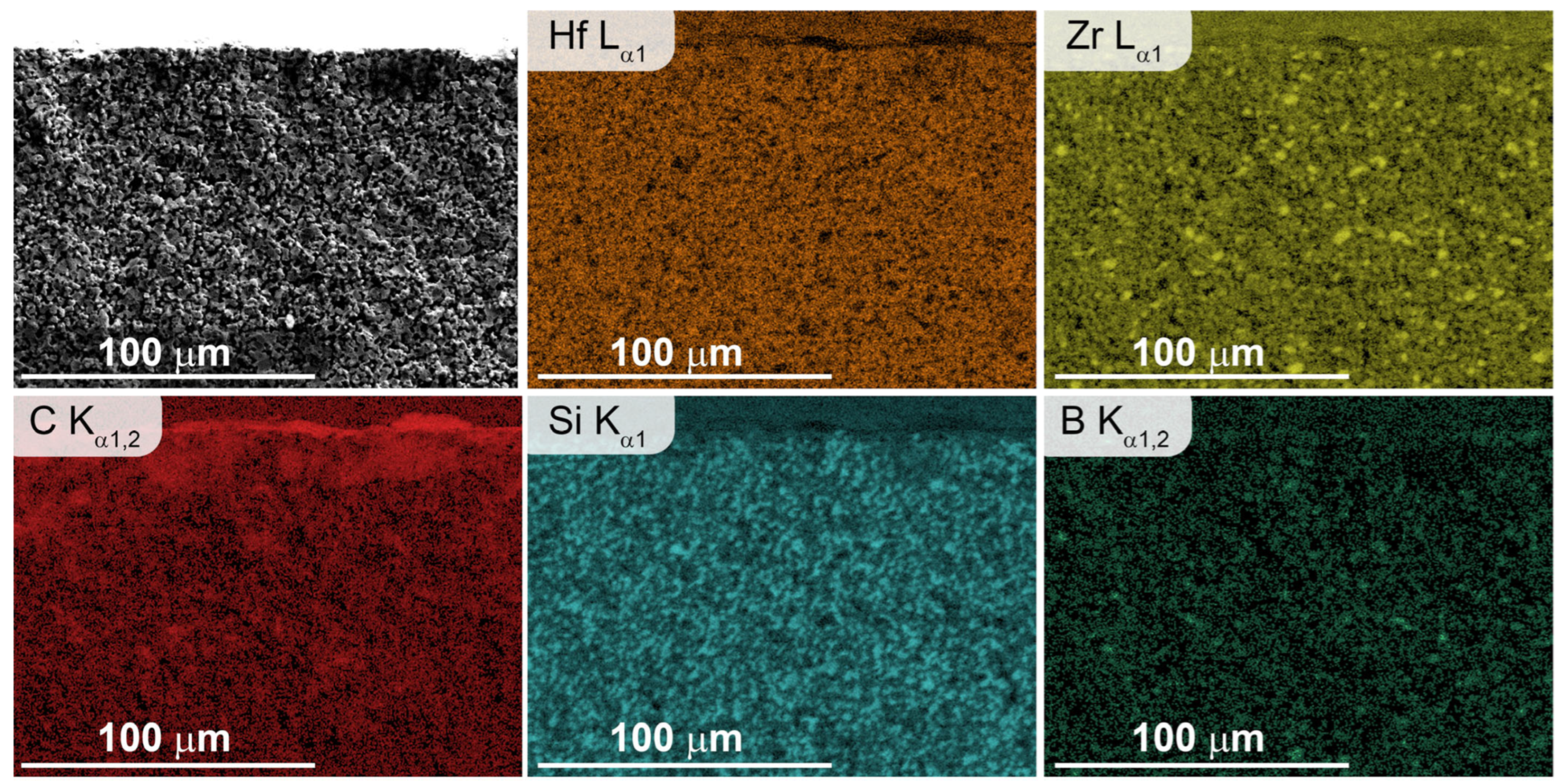
The conclusions regarding the composition and thickness of the degradation layer under the high-enthalpy N2+CH4 plasma flow of the ZrB2-HfB2-SiC-CCNT ceramic composite can also be verified through the distribution of the basic elements: Hf, Zr, Si, C, and B (Figure 10): a near-surface concentration of carbon is observed. Silicon carbide grains are distributed evenly throughout the ceramic volume; their content decreases closer to the surface. As previously mentioned, the presence of cores with a predominant zirconium content, distributed in the grains of the HfB2-ZrB2 solid solution, is individually illustrated for the composite volume. In general, the degradation depth of this ceramic material, although close to that noted for a material of similar composition and properties (HfB2-30 vol%SiC)-2 vol%C (graphene), subjected to a subsonic N2-plasma flow as well, is nevertheless somewhat greater. This may be related to the higher average surface temperature of 2115–2230 °C, compared to 2170–2190 °C.

4. Conclusions

For the first time, the behavior of ultrahigh-temperature ceramics modified with multi-walled carbon nanotubes has been studied under exposure to subsonic flows of dissociated nitrogen with the addition of 5 mol% methane, simulating aerodynamic heating of the material in Titan’s atmosphere. The composition used as an example was 31.5 vol.% ZrB2-31.5 vol.% HfB2-27 vol.% SiC-10 vol.% CCNT. Summarizing the obtained results, several short conclusions can be drawn:
  • The heat flux to a cold copper wall, determined for the plasma based on nitrogen modified with 5 mol% methane, was 315 W/cm2. At the same time, an increase in the plasma radiation intensity was observed compared to the pure nitrogen plasma jet under the same facility parameters (anode power, pressure, and gas flow rate). This increase was also expressed in a significantly higher intensity of the N2+ and CN lines in the emission spectrum of the 95 mol% N2–5 mol% CH4 plasma composition compared to the N2 plasma spectrum. Additionally, emission spectroscopy data revealed the presence of C2 in the composition of the high-enthalpy jet.
  • From the point of view of the effect on the sample, it is necessary to state that there are both similarities and differences in the behavior of the ceramic under the action of dissociated individual nitrogen and the N2+CH4 gas mixture with respect to the pure N2 plasma flow. Namely:
    • In both cases, there is no silicon carbide on the surface of the sample, which is likely to be destroyed under the influence of a temperature of 2100–2230 °C and reduced pressure, with transition to the gas phase, or to react with atomic nitrogen or hydrogen-containing particles to form gaseous products.
    • Partially, zirconium and hafnium diborides are converted into a solid solution with a cubic structure, most likely, based on metal monoborides with an admixture of monocarbides and mononitrides, which is close to the behavior of ZrB2(HfB2)-SiC-C ceramics under the action of not a subsonic but a supersonic flow of dissociated nitrogen. In a subsonic flow of nitrogen without the addition of methane, it was previously shown that a lower hafnium nitride with the composition Hf3N2 is formed [36].
    • The introduction of methane into the subsonic flow of dissociated nitrogen leads to the formation of a carbon layer on the surface, which includes both amorphized carbon and diamond-like coatings, as evidenced by the combined data of XRD, Raman spectroscopy, SEM, and energy-dispersive analysis of the sample. This significant change in the composition and microstructure of the ultrahigh-temperature ceramic surface affects its emissivity and can impact the catalytic component of further sample heating.
In general, the experiment demonstrated that introducing even a small amount of a second gaseous component (5 mol% methane) into the composition of the high-enthalpy flow of dissociated nitrogen can significantly affect both the thermal behavior of ultrahigh-temperature ceramics and the process of its surface degradation. The initial data obtained indicate the need for comprehensive and meticulous research to identify how varying heat fluxes, pressure, and gas mixture composition influence these materials. These studies are necessary to accurately assess the prospects of using ZrB2(HfB2)-SiC-based materials in the design of probes to explore the planets and moons of the solar system (e.g., Titan).

Author Contributions

Conceptualization, E.P.S. and A.V.C.; methodology, A.F.K. and N.T.K.; investigation, A.V.C., E.P.S., N.P.S., I.V.L., S.S.G., A.S.L., I.A.N. and A.S.M.; writing—original draft preparation, E.P.S. and A.V.C.; writing—review and editing, N.P.S., I.V.L., S.S.G., A.S.L., I.A.N., A.S.M. and A.F.K.; visualization, E.P.S., N.P.S., S.S.G. and A.V.C.; supervision, A.F.K. and N.T.K.; project administration, A.V.C. and E.P.S.; funding acquisition, A.V.C. All authors have read and agreed to the published version of the manuscript.

Funding

This research was supported by the Russian Science Foundation (project No. 22-79-10083, https://rscf.ru/en/project/22-79-10083/, accessed on 9 April 2025).

Institutional Review Board Statement

Not applicable.

Informed Consent Statement

Not applicable.

Data Availability Statement

Data are contained within this article.

Conflicts of Interest

The authors declare no conflicts of interest.

References

  1. Simonenko, E.P.; Sevast’yanov, D.V.; Simonenko, N.P.; Sevast’yanov, V.G.; Kuznetsov, N.T. Promising Ultra-High-Temperature Ceramic Materials for Aerospace Applications. Russ. J. Inorg. Chem. 2013, 58, 1669–1693. [Google Scholar] [CrossRef]
  2. Squire, T.H.; Marschall, J. Material Property Requirements for Analysis and Design of UHTC Components in Hypersonic Applications. J. Eur. Ceram. Soc. 2010, 30, 2239–2251. [Google Scholar] [CrossRef]
  3. Jin, X.; He, R.; Zhang, X.; Hu, P. Ablation Behavior of ZrB2–SiC Sharp Leading Edges. J. Alloys Compd. 2013, 566, 125–130. [Google Scholar] [CrossRef]
  4. Samsonov, G.V.; Bolgar, A.S.; Guseva, E.A.; Klochkov, L.A.; Kovenskaya, B.A.; Serebryakova, T.I.; Timofeeva, I.I.; Turchanin, A.G.; Fesenko, V.V. Thermophysical Properties of Transition Metal Carbides and Diborides. High Temp.-High Press. 1973, 5, 29–33. [Google Scholar]
  5. Guria, J.F.; Bansal, A.; Kumar, V. Effect of Additives on the Thermal Conductivity of Zirconium Diboride Based Composites—A Review. J. Eur. Ceram. Soc. 2021, 41, 1–23. [Google Scholar] [CrossRef]
  6. Harrington, G.J.K.; Hilmas, G.E. Thermal Conductivity of ZrB 2 and HfB 2. In Ultra-High Temperature Ceramics; Wiley: Hoboken, NJ, USA, 2014; pp. 197–235. [Google Scholar]
  7. Balat-Pichelin, M.; Bêche, E.; Sciti, D.; Alfano, D. Emissivity, Catalycity and Microstructural Characterization of ZrB2–SiCfiber Based UHTC at High Temperature in a Non-Equilibrium Air Plasma Flow. Ceram. Int. 2014, 40, 9731–9742. [Google Scholar] [CrossRef]
  8. Meng, S.; Zeng, Q.; Jin, H.; Wang, L.; Xu, C. Evaluation of Atomic Oxygen Catalytic Coefficient of ZrB2 –SiC by Laser-Induced Fluorescence up to 1473 K. Meas. Sci. Technol. 2018, 29, 075207. [Google Scholar] [CrossRef]
  9. Li, N.; Hu, P.; Zhang, X.; Liu, Y.; Han, W. Effects of Oxygen Partial Pressure and Atomic Oxygen on the Microstructure of Oxide Scale of ZrB2–SiC Composites at 1500°C. Corros. Sci. 2013, 73, 44–53. [Google Scholar] [CrossRef]
  10. Marschall, J.; Chamberlain, A.; Crunkleton, D.; Rogers, B. Catalytic Atom Recombination on ZrB2/SiC and HfB2/SiC Ultrahigh-Temperature Ceramic Composites. J. Spacecr. Rocket. 2004, 41, 576–581. [Google Scholar] [CrossRef]
  11. Marschall, J.; Pejakovic, D.; Fahrenholtz, W.G.; Hilmas, G.E.; Panerai, F.; Chazot, O. Temperature Jump Phenomenon during Plasmatron Testing of ZrB2-SiC Ultrahigh-Temperature Ceramics. J. Thermophys. Heat Transf. 2012, 26, 559–572. [Google Scholar] [CrossRef]
  12. Wang, D.; Zhang, Y.; Jiao, Y.; Wei, B.; Ding, X.; Jin, X.; Ran, S. Reactive Spark Plasma Sintering of an Electrically Conductive B4C-SiC-ZrB2 Composite with Enhanced Mechanical Properties. J. Eur. Ceram. Soc. 2024, 44, 2720–2729. [Google Scholar] [CrossRef]
  13. Ahmadi, Z.; Shahedi Asl, M.; Zakeri, M.; Farvizi, M. On the Reactive Spark Plasma Sinterability of ZrB2–SiC–TiN Composite. J. Alloys Compd. 2022, 909, 164611. [Google Scholar] [CrossRef]
  14. Duan, X.; Wei, C.; Geng, X.; Meng, F.; Zhou, L.; Wang, P.; Dong, Z.; Dong, S. Effects of Adding Si3N4 Whiskers to ZrB2–SiC Ceramics on Microstructure, Mechanical Properties and Oxidation Resistance. Ceram. Int. 2024, 50, 43153–43164. [Google Scholar] [CrossRef]
  15. Simonenko, E.P.; Simonenko, N.P.; Sevastyanov, V.G.; Kuznetsov, N.T. ZrB2/HfB2–SiC Ultra-High-Temperature Ceramic Materials Modified by Carbon Components: The Review. Russ. J. Inorg. Chem. 2018, 63, 1772–1795. [Google Scholar] [CrossRef]
  16. Yang, B.; Kuang, C.; Liu, Z.; Yu, C.; Deng, C.; Ding, J. Effect of Nano-Graphite on Mechanical Properties and Oxidation Resistance of ZrB2–SiC–Graphite Electrode Ceramics. J. Iron Steel Res. Int. 2024, 31, 1502–1513. [Google Scholar] [CrossRef]
  17. Asl, M.S.; Balak, Z. Fabrication and Characterization of ZrB2 Ceramic in Presence of Graphite Platelet and SiC. Silicon 2023, 15, 6911–6919. [Google Scholar] [CrossRef]
  18. Simonenko, E.P.; Simonenko, N.P.; Kolesnikov, A.F.; Chaplygin, A.V.; Lysenkov, A.S.; Nagornov, I.A.; Mokrushin, A.S.; Kuznetsov, N.T. Investigation of the Effect of Supersonic Flow of Dissociated Nitrogen on ZrB2–HfB2–SiC Ceramics Doped with 10 Vol.% Carbon Nanotubes. Materials 2022, 15, 8507. [Google Scholar] [CrossRef]
  19. Tripathi, S.; Bhadauria, A.; Tiwari, A.; Tiwari, A.K. Effect of Carbonaceous Reinforcements on Mechanical Properties of ZrB2-SiC Composites via Nanoindentation Study. Diam. Relat. Mater. 2023, 140, 110537. [Google Scholar] [CrossRef]
  20. He, L.; Wu, J.; Meng, Q.; Sun, Y.; Pan, J.; Tian, Y.; Wu, F. Study on Low Content Short Carbon Fibers to Enhance Mechanical Properties of ZrB2-SiC Composites with Improved Damage Tolerance. Mater. Today Commun. 2025, 42, 111391. [Google Scholar] [CrossRef]
  21. Chen, Y. ULTRA-HIGH-TEMPERATURE CERAMIC MATERIALS MODIFIED BY GRAPHENE: AN OVERVIEW. Ceram.-Silikaty 2023, 67, 260–296. [Google Scholar] [CrossRef]
  22. Simonenko, E.P.; Simonenko, N.P.; Kolesnikov, A.F.; Chaplygin, A.V.; Lysenkov, A.S.; Nagornov, I.A.; Simonenko, T.L.; Gubin, S.P.; Sevastyanov, V.G.; Kuznetsov, N.T. Oxidation of Graphene-Modified HfB2-SiC Ceramics by Supersonic Dissociated Air Flow. J. Eur. Ceram. Soc. 2022, 42, 30–42. [Google Scholar] [CrossRef]
  23. Simonenko, E.P.; Kolesnikov, A.F.; Chaplygin, A.V.; Lysenkov, A.S.; Nagornov, I.A.; Lukomskii, I.V.; Galkin, S.S.; Mokrushin, A.S.; Simonenko, N.P.; Kuznetsov, N.T. Transformation of the Surface of HfB2–SiC–C(Graphene) Ultrahigh-Temperature Ceramics in a High-Velocity Flow of Dissociated Nitrogen. Russ. J. Inorg. Chem. 2024, 69, 517–527. [Google Scholar] [CrossRef]
  24. Simonenko, E.P.; Kolesnikov, A.F.; Chaplygin, A.V.; Kotov, M.A.; Yakimov, M.Y.; Lukomskii, I.V.; Galkin, S.S.; Shemyakin, A.N.; Solovyov, N.G.; Lysenkov, A.S.; et al. Oxidation of Ceramic Materials Based on HfB2-SiC under the Influence of Supersonic CO2 Jets and Additional Laser Heating. Int. J. Mol. Sci. 2023, 24, 13634. [Google Scholar] [CrossRef] [PubMed]
  25. Simonenko, E.P.; Simonenko, N.P.; Kolesnikov, A.F.; Chaplygin, A.V.; Sakharov, V.I.; Lysenkov, A.S.; Nagornov, I.A.; Kuznetsov, N.T. Effect of 2 Vol % Graphene Additive on Heat Transfer of Ceramic Material in Underexpanded Jets of Dissociated Air. Russ. J. Inorg. Chem. 2022, 67, 2050–2061. [Google Scholar] [CrossRef]
  26. Cheng, Y.; Liu, Y.; An, Y.; Hu, N. High Thermal-Conductivity RGO/ZrB2-SiC Ceramics Consolidated from ZrB2-SiC Particles Decorated GO Hybrid Foam with Enhanced Thermal Shock Resistance. J. Eur. Ceram. Soc. 2020, 40, 2760–2767. [Google Scholar] [CrossRef]
  27. Zhang, B.; Zhang, X.; Hong, C.; Qiu, Y.; Zhang, J.; Han, J.; Hu, P. Electrostatic Assembly Preparation of High-Toughness Zirconium Diboride-Based Ceramic Composites with Enhanced Thermal Shock Resistance Performance. ACS Appl. Mater. Interfaces 2016, 8, 11675–11681. [Google Scholar] [CrossRef]
  28. Wang, A.; Hu, P.; Zhang, X.; Zhang, D.; Fang, C. Thermal Shock Behavior of ZrB2-Based Sharp Leading Edges Evaluated by a Novel Water Spraying Method. Ceram. Int. 2018, 44, 2376–2382. [Google Scholar] [CrossRef]
  29. Boulos, M.I.; Auweter-Kurtz, M.; Fauchais, P.L.; Pfender, E. Plasma in the Aerospace Industry. In Handbook of Thermal Plasmas; Springer International Publishing: Cham, Germany, 2023; pp. 1509–1580. [Google Scholar]
  30. Chinnaraj, R.K.; Hong, S.M.; Kim, H.S.; Oh, P.Y.; Choi, S.M. Ablation Experiments of Ultra-High-Temperature Ceramic Coating on Carbon–Carbon Composite Using ICP Plasma Wind Tunnel. Int. J. Aeronaut. Space Sci. 2020, 21, 889–905. [Google Scholar] [CrossRef]
  31. Simonenko, E.P.; Papynov, E.K.; Shichalin, O.O.; Belov, A.A.; Nagornov, I.A.; Simonenko, T.L.; Gorobtsov, P.Y.; Teplonogova, M.A.; Mokrushin, A.S.; Simonenko, N.P.; et al. Reactive Spark Plasma Sintering and Oxidation of ZrB2-SiC and ZrB2-HfB2-SiC Ceramic Materials. Ceramics 2024, 7, 1566–1584. [Google Scholar] [CrossRef]
  32. Carandente, V.; Savino, R.; Esposito, A.; Zuppardi, G.; Caso, V. Experimental and Numerical Simulation, by an Arc-Jet Facility, of Hypersonic Flow in Titan’s Atmosphere. Exp. Therm. Fluid Sci. 2013, 48, 97–101. [Google Scholar] [CrossRef]
  33. Savino, R.; De Stefano Fumo, M.; Silvestroni, L.; Sciti, D. Arc-Jet Testing on HfB2 and HfC-Based Ultra-High Temperature Ceramic Materials. J. Eur. Ceram. Soc. 2008, 28, 1899–1907. [Google Scholar] [CrossRef]
  34. Silvestroni, L.; Mungiguerra, S.; Sciti, D.; Di Martino, G.D.; Savino, R. Effect of Hypersonic Flow Chemical Composition on the Oxidation Behavior of a Super-Strong UHTC. Corros. Sci. 2019, 159, 108125. [Google Scholar] [CrossRef]
  35. Kolesnikov, A.F.; Kuznetsov, N.T.; Murav’eva, T.I.; Nagornov, I.A.; Sakharov, V.I.; Sevastyanov, V.G.; Simonenko, E.P.; Simonenko, N.P.; Chaplygin, A.V.; Shcherbakova, O.O. Investigation of Heat Transfer to HfB2-SiC-Based Ceramics in Underexpanded Dissociated-Nitrogen Jets and Analysis of the Surface. Fluid Dyn. 2022, 57, 513–523. [Google Scholar] [CrossRef]
  36. Simonenko, E.P.; Simonenko, N.P.; Chaplygin, A.V.; Lukomskii, I.V.; Galkin, S.S.; Lysenkov, A.S.; Nagornov, I.A.; Mokrushin, A.S.; Kolesnikov, A.F.; Kuznetsov, N.T. Surface Degradation of Ultrahigh-Temperature Ceramics Based on HfB2–30vol%SiC in Subsonic Nitrogen Plasma Flow. Int. J. Refract. Met. Hard Mater. 2025, 130, 107139. [Google Scholar] [CrossRef]
  37. Nixon, C.A. The Composition and Chemistry of Titan’s Atmosphere. ACS Earth Space Chem. 2024, 8, 406–456. [Google Scholar] [CrossRef] [PubMed]
  38. Owen, T. The Composition and Origin of Titan’s Atmosphere. Planet. Space Sci. 1982, 30, 833–838. [Google Scholar] [CrossRef]
  39. Chaplygin, A.V.; Vasil’evskii, S.A.; Galkin, S.S.; Kolesnikov, A.F. Thermal State of Uncooled Quartz Discharge Channel of Powerful High-Frequency Induction Plasmatron. Phys. Kinet. Gas Dyn. 2022, 23, 38–56. [Google Scholar] [CrossRef]
  40. Gordeev, A. Overview of Characteristics and Experiments in IPM Plasmatrons. In VKI, RTO AVT/VKI Special Course on Measurement Techniques for High Enthalpy Plasma Flows; RTO EN-8; Defense Technical Information Center: Fort Belvoir, VA, USA, 1999; Available online: https://apps.dtic.mil/sti/citations/ADP010736 (accessed on 1 June 2025).
  41. Chaplygin, A.; Simonenko, E.; Simonenko, N.; Kotov, M.; Yakimov, M.; Lukomskii, I.; Galkin, S.; Kolesnikov, A.; Vasil’evskii, S.; Shemyakin, A.; et al. Heat Transfer and Behavior of Ultra High Temperature Ceramic Materials under Exposure to Supersonic Carbon Dioxide Plasma with Additional Laser Irradiation. Int. J. Therm. Sci. 2024, 201, 109005. [Google Scholar] [CrossRef]
  42. Chaplygin, A.; Yakimov, M.; Vasil’evskii, S.; Kotov, M.; Lukomskii, I.; Galkin, S.; Shemyakin, A.; Solovyov, N.; Kolesnikov, A. Combined Plasma and Laser Heating of Graphite. Plasma 2025, 8, 9. [Google Scholar] [CrossRef]
  43. Roeck, W.; Auweter-Kurtz, M. Experimental Investigation of the Huygens Entry into the Titan Atmosphere within a Plasma Wind Tunnel. In Proceedings of the 30th Thermophysics Conference, San Diego, CA, USA, 19–22 June 1995; American Institute of Aeronautics and Astronautics: Reston, VA, USA, 1995. [Google Scholar]
  44. Playez, M.; Vancrayenest, B.; Zuber, M.E.; Fletcher, D.G. Titan Atmosphere Plasma Investigation Using Spectroscopic Techniques. In Proceedings of the Fifth European Symposium on Aerothermodynamics for Space Vehicles, Cologne, Germany, 8–11 November 2005; pp. 1–6. [Google Scholar]
  45. Kouakou, P.; Brien, V.; Assouar, B.; Hody, V.; Belmahi, M.; Migeon, H.N.; Bougdira, J. Preliminary Synthesis of Carbon Nitride Thin Films by N2/CH4 Microwave Plasma Assisted Chemical Vapour Deposition: Characterisation of the Discharge and the Obtained Films. Plasma Process. Polym. 2007, 4, S210–S214. [Google Scholar] [CrossRef]
  46. Bulou, S.; Le Brizoual, L.; Hugon, R.; De Poucques, L.; Belmahi, M.; Migeon, H.; Bougdira, J. Characterization of a N2/CH4 Microwave Plasma With a Solid Additive Si Source Used for SiCN Deposition. Plasma Process. Polym. 2009, 6, S576–S581. [Google Scholar] [CrossRef]
  47. Vacher, D.; Dudeck, M.; André, P.; Lino da Silva, M.; Faure, G.; Dubois, M.; Hamwi, A. Radiation from an Inductively Coupled Plasma in the Near-UV to near-IR Spectral Region for a Titan-Type N2-CH4 Mixture. In Proceedings of the EUCASS, the European Conference for AeroSpace Sciences; p. 184. Available online: https://www.eucass.eu/component/docindexer/?task=download&id=6310 (accessed on 1 June 2025).
  48. Holleck, H. Legierungsverhalten von HfB2 Mit Uran- Und Übergangsmetalldiboriden. J. Nucl. Mater. 1967, 21, 14–20. [Google Scholar] [CrossRef]
  49. Kugai, L.N. Chemical Stability of Borides of Transition Metals of Groups IV-VI Inalkaline Solutions. Izv. Akad. Nauk Neorg. Mater. 1972, 8, 669–670. (In Russian) [Google Scholar]
  50. Braekken, H. Zur Kristallstruktur Des Kubischen Karborunds. Z. Krist. 1930, 75, 572–573. [Google Scholar]
  51. Shulishova, O.I.; Shcherbak, I.A. Superconductivity of the Borides of Transition and Rare-Earth Metals. Inorg. Mater. 1967, 3, 1304–1306. [Google Scholar]
  52. Wyckoff, R.W.G. Second Edition. Interscience Publishers, New York, New Yorkrocksalt Structure. Cryst. Struct. 1963, 1, 85–237. [Google Scholar]
  53. Becker, K.; Ebert, F. Die Kristallstruktur Einiger Binärer Carbide Und Nitride. Z. Phys. 1925, 31, 268–272. [Google Scholar] [CrossRef]
  54. Rudy, E. The Crystal Structures of Hf3N2 and Hf4N3. Metall. Mater. Trans. B 1970, 1, 1249–1252. [Google Scholar] [CrossRef]
  55. Li, Y.; Mu, L.; Hu, Y.-S.; Li, H.; Chen, L.; Huang, X. Pitch-Derived Amorphous Carbon as High Performance Anode for Sodium-Ion Batteries. Energy Storage Mater. 2016, 2, 139–145. [Google Scholar] [CrossRef]
  56. Chen, P.; Huang, F.; Yun, S. Characterization of the Condensed Carbon in Detonation Soot. Carbon N. Y. 2003, 41, 2093–2099. [Google Scholar] [CrossRef]
  57. TRUCANO, P.; CHEN, R. Structure of Graphite by Neutron Diffraction. Nature 1975, 258, 136–137. [Google Scholar] [CrossRef]
  58. Fayos, J. Possible 3D Carbon Structures as Progressive Intermediates in Graphite to Diamond Phase Transition. J. Solid State Chem. 1999, 148, 278–285. [Google Scholar] [CrossRef]
  59. Larichev, Y.V.; Yeletsky, P.M.; Yakovlev, V.A. Study of Silica Templates in the Rice Husk and the Carbon–Silica Nanocomposites Produced from Rice Husk. J. Phys. Chem. Solids 2015, 87, 58–63. [Google Scholar] [CrossRef]
  60. Bechelany, M.; Brioude, A.; Cornu, D.; Ferro, G.; Miele, P. A Raman Spectroscopy Study of Individual SiC Nanowires. Adv. Funct. Mater. 2007, 17, 939–943. [Google Scholar] [CrossRef]
  61. Burton, J.C.; Sun, L.; Long, F.H.; Feng, Z.C.; Ferguson, I.T. First- and Second-Order Raman Scattering from Semi-Insulating 4-H SiC. Phys. Rev. B 1999, 59, 7282–7284. [Google Scholar] [CrossRef]
  62. Jiang, C.; Zhao, J.; Therese, H.A.; Friedrich, M.; Mews, A. Raman Imaging and Spectroscopy of Heterogeneous Individual Carbon Nanotubes. J. Phys. Chem. B 2003, 107, 8742–8745. [Google Scholar] [CrossRef]
  63. Dresselhaus, M.S.; Jorio, A.; Hofmann, M.; Dresselhaus, G.; Saito, R. Perspectives on Carbon Nanotubes and Graphene Raman Spectroscopy. Nano Lett. 2010, 10, 751–758. [Google Scholar] [CrossRef] [PubMed]
  64. Robertson, J. Diamond-like Amorphous Carbon. Mater. Sci. Eng. R Rep. 2002, 37, 129–281. [Google Scholar] [CrossRef]
  65. Argibay, N.; Babuska, T.F.; Curry, J.F.; Dugger, M.T.; Lu, P.; Adams, D.P.; Nation, B.L.; Doyle, B.L.; Pham, M.; Pimentel, A.; et al. In-Situ Tribochemical Formation of Self-Lubricating Diamond-like Carbon Films. Carbon N. Y. 2018, 138, 61–68. [Google Scholar] [CrossRef]
  66. Das, S.; Mojumder, S.; Saha, D.; Pal, M. Influence of Major Parameters on the Sensing Mechanism of Semiconductor Metal Oxide Based Chemiresistive Gas Sensors: A Review Focused on Personalized Healthcare. Sens. Actuators B Chem. 2022, 352, 131066. [Google Scholar] [CrossRef]
  67. Ashfold, M.N.R.; Mankelevich, Y.A. Self-Consistent Modeling of Microwave Activated N2/CH4/H2 (and N2/H2) Plasmas Relevant to Diamond Chemical Vapor Deposition. Plasma Sources Sci. Technol. 2022, 31, 035005. [Google Scholar] [CrossRef]
  68. Almeida, L.S.; Souza, A.R.M.; Costa, L.H.; Rangel, E.C.; Manfrinato, M.D.; Rossino, L.S. Effect of Nitrogen in the Properties of Diamond-like Carbon (DLC) Coating on Ti 6 Al 4 V Substrate. Mater. Res. Express 2020, 7, 065601. [Google Scholar] [CrossRef]
  69. Badzian, A.; Badzian, T.; Lee, S.-T. Synthesis of Diamond from Methane and Nitrogen Mixture. Appl. Phys. Lett. 1993, 62, 3432–3434. [Google Scholar] [CrossRef]
  70. Carandente, V.; Caso, V.; Esposito, A.; Savino, R.; Zuppardi, G. Simulation of Titan Atmosphere by an Arc-Heated Facility. In Proceedings of the Ntervento Presentato al Convegno 9th International Planetary Probe Workshop, Toulouse, France, 18–22 June 2012; pp. 1–6. [Google Scholar]
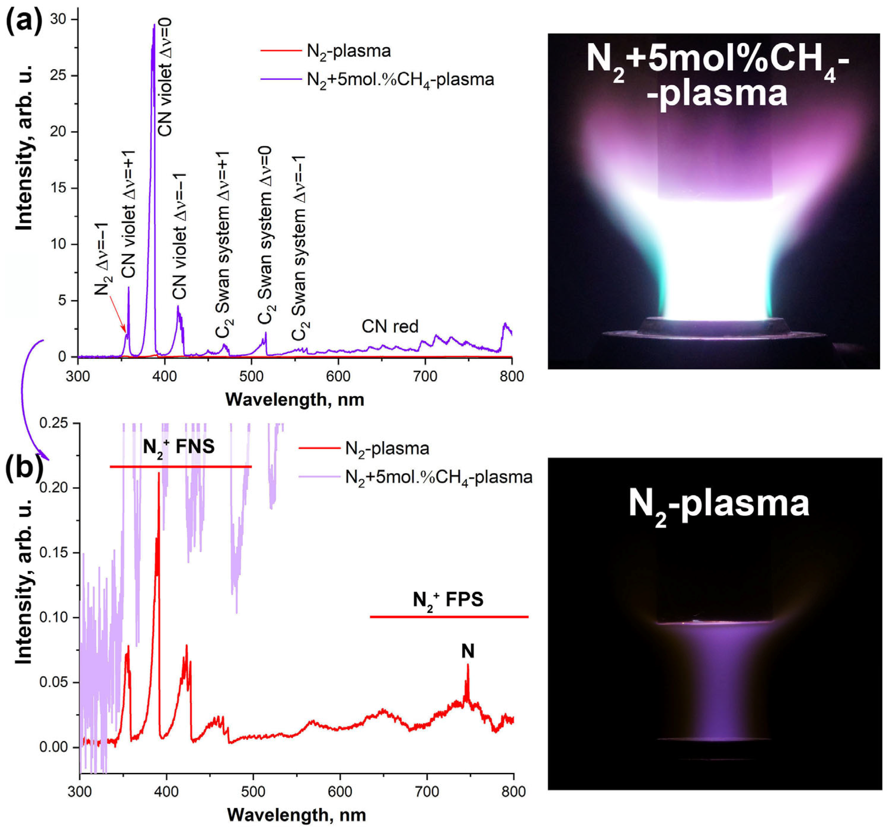
Figure 1. Optical emission spectrum of a N2 plasma jet containing 5 mol% CH4 (purple, (a)), including a comparison with the spectrum of N2 plasma (red, (b)), as well as corresponding photographs of the appearance of a cylindrical water-cooled heat flux probe (reproduced exposure conditions on the sample: N = 45 kW, p = 8⋅103 Pa, 2.4 g/s); FNS—first negative system; FPS—first positive system.
Ceramics 08 00067 g001
Figure 2. The appearance of the ZrB2-HfB2-SiC-CCNT sample in the water-cooled model at the 3rd minute of exposure (a) and the evolution of the average surface temperature in the central region (T, red curve) as a function of anode power (N, blue curve), pressure in the plasmatron test chamber (P, green curve), and exposure time (b).
Ceramics 08 00067 g002
Figure 3. Thermal images of the ZrB2-HfB2-SiC-CCNT sample surface at specific moments during exposure to a subsonic N2+CH4 plasma flow (top) and the corresponding temperature distributions along the diameter (bottom).
Ceramics 08 00067 g003
Figure 4. X-ray diffraction patterns of the initial ZrB2-HfB2-SiC-CCNT sample surface (a) and after exposure to a subsonic N2+CH4 plasma flow (b).
Ceramics 08 00067 g004
Figure 5. Raman spectra of the initial ZrB2-HfB2-SiC-CCNT sample surface (a) and after exposure to a subsonic N2+CH4 plasma flow (b).
Ceramics 08 00067 g005
Figure 6. SEM image of the ZrB2-HfB2-SiC-CCNT sample surface after exposure to a subsonic N2+CH4 plasma flow (ad), acquired at an accelerating voltage of 5 kV.
Ceramics 08 00067 g006
Figure 7. Surface distribution mapping of the elements C*, Zr, and Hf on the ZrB2-HfB2-SiC-CCNT sample after thermochemical treatment, accelerating voltage 20 kV; *carbon distribution is approximate.
Ceramics 08 00067 g007
Figure 8. Microstructure of ZrB2-HfB2-SiC-CCNT sample slip from SEM data; accelerating voltages of 2 (left) and 20 kV (right); arrows indicate horizontal cracks.
Ceramics 08 00067 g008
Figure 9. Microstructure of the ZrB2-HfB2-SiC-CCNT sample slip after exposure to a subsonic N2+CH4 plasma flow with superimposed EDX analysis data on the degradation depth; arrows indicate horizontal cracks.
Ceramics 08 00067 g009
Figure 10. Mapping of the distribution of elements Hf, Zr, C*, Si, and B* across the ZrB2-HfB2-SiC-CCNT sample’s fracture after thermochemical treatment, accelerating voltage of 20 kV; *carbon and boron distributions are approximate.
Ceramics 08 00067 g010
Disclaimer/Publisher’s Note: The statements, opinions and data contained in all publications are solely those of the individual author(s) and contributor(s) and not of MDPI and/or the editor(s). MDPI and/or the editor(s) disclaim responsibility for any injury to people or property resulting from any ideas, methods, instructions or products referred to in the content.