Article

Improving the Transparency of a MgAl2O4 Spinel Damaged by Sandblasting through a SiO2-ZrO2 Coating

1
Emerging Materials Research Unit, Ferhat Abbas University Setif 1, Setif 19000, Algeria
2
Optics and Precision Mechanics Institute, Ferhat Abbas University Setif 1, Setif 19000, Algeria
3
Laboratory of Non-Metallic Materials, Optics and Precision Mechanics Institute, Ferhat Abbas University Setif 1, Setif 19000, Algeria
4
Laboratory of Applied Optics, Institute of Optics and Precision Mechanics, University Ferhat Abbas Setif 1, Setif 19000, Algeria
5
Institut National des Sciences Appliquées Lyon, Université Claude Bernard Lyon 1, CNRS, MATEIS, UMR5510, 69621 Villeurbanne, France
6
Instituto de Cerámica y Vidrio (CSIC), Campus de Cantoblanco, 28049 Madrid, Spain
*
Author to whom correspondence should be addressed.
Ceramics 2024, 7(2), 743-758; https://doi.org/10.3390/ceramics7020049
Submission received: 4 March 2024 / Revised: 15 May 2024 / Accepted: 22 May 2024 / Published: 28 May 2024
(This article belongs to the Special Issue Transparent Ceramics—a Theme Issue in Honor of Dr. Adrian Goldstein)

Abstract

:
Transparent materials in contact with harmful environments such as sandstorms are exposed to surface damage. Transparent MgAl2O4 spinel used as protective window, lens or laser exit port, among others, is one of the materials affected by natural aggressions. The impact of sand particles can cause significant defects on the exposed surface, thus affecting its optical and mechanical behavior. The aim of this work is to improve the surface state of a spinel damaged surface by the deposition of a thin layer of SiO2-ZrO2. For this purpose, spinel samples obtained from different commercial powders sintered by Spark Plasma Sintering were sandblasted and further coated with a SiO2-ZrO2 thin layer. The coating was successfully synthesized by the sol/gel method, deposited on the sandblasted samples and then treated at 900 °C, reaching a final thickness of 250 nm. The results indicated that sandblasting significantly affects the surface of the spinel samples as well as the optical transmission, confirmed by UV-visible spectroscopy and profilometry tests. However, the deposition of a SiO2-ZrO2 coating modifies the UV-visible response. Thus, the optical transmission of the S25CRX12 sample presents the best transmission values of 81%, followed by the S25CRX14 sample then the S30CR sample at 550 nm wavelength. An important difference was observed between sandblasted samples and coated samples at low and high wavelengths. At low wavelengths (around 200 nm), sandblasting tends to improve significantly the transmission of spinel samples, which exhibit a low transmission in the pristine state. This phenomenon can be attributed to the healing of small superficial defects responsible for the degradation of transmission such as pores or flaws. When the initial transmission at 200 nm is high, the sandblasting worsens the transmission. Sandblasting reduces slightly the transmission values for long wavelengths due to the formation of large superficial defects like chipping by creation and propagation of lateral cracks. The coating of the sandblasted samples exhibits some healing of defects induced by sandblasting. The deposition of the SiO2-ZrO2 layer induces a clear increase in the optical transmission values, sometimes exceeding the initial values of the transmission in the pristine state.

Graphical Abstract

1. Introduction

The degradation of optical and mechanical properties of materials used for precise imaging and detection of IR or near-IR radiation produced by particles suspended in the air, such as silica particles in the Saharan regions, is a serious problem [1,2]. Transparent ceramics are very promising materials in the field of protection of IR detection devices thanks to their high transparency in the range between 300 and 900 nm wavelength and their interesting mechanical properties [3,4]. However, these materials suffer erosion–corrosion as a consequence of the exposition of natural attacks such as sandstorms. Studies based on the fragility of materials such as glass are numerous, but in the case of transparent ceramics, they are limited. In fact, numerous works of research [5,6] have shown that erosion of brittle materials is affected by many factors, including the properties of the incident particles (properties of the target materials (i.e., their hardness, fracture toughness and their surface condition) and the test conditions (i.e., impact speed, impact angle and temperature). During sandstorms, all these factors take place at the same time and in a random way (wide range of grain size, variable shape of sand particles, variable speeds during the same storm, variable impact angles, etc.), producing defects in the surface. Indeed, the cracks and defects created act as effective scattering centers for the incident radiation. Therefore, optical transmission and resolution are affected, decreasing the performance of detection equipment. Cracking also weakens the material and may be enough to cause failure of the protective window [3].
Magnesium aluminate spinel (MgAl2O4) is one of the most important ceramic materials used as transparent shielding ceramics and also as protective windows for sensor applications in aeronautics since these applications require high optical and mechanical performances [7,8,9]. Spinel possesses very good mechanical properties, i.e., hardness, toughness and wear resistance, high transmission and an appropriate refractive index [10,11]. For possible applications in aggressive environments, these characteristics should be preserved for a long time to maintain the structural integrity and optical transparency. Mechanical properties and transparency depend on powder characteristics (particle size and chemical purity) and subsequent sintering conditions. Only a few research studies have addressed the surface degradation of transparent spinel. For example, Lallemant et al. [2] studied the erosion of several types of transparent materials including spinel. They observed that the increase in surface roughness caused by erosion directly affected the optical quality of spinel. They concluded that the variation depends on three parameters: wavelength, microstructure and hardness. Thus, if the size of the defects (roughness Rq) is small compared to the wavelength, the reflectance of the surface increases, and, consequently, the optical properties also increase, except for the infrared, where the variation can be neglected. Tokariev et al. [8] reported that coarse-grained spinel wear resists erosion better than fine-grained spinel. On the other hand, Von Helden et al. [4] studied the behavior of spinel under abrasion by performing erosion tests using sand particles at different durations. They found that spinel exhibits minimal degradation of its surface state after erosion and that hardness has a direct influence on short-term wear of the samples. However, the stress intensity factor KIC influenced long-term wear.
To improve the wear resistance of spinel, different groups of researchers have considered two different approaches: (1) to strengthen the mechanical properties of the surface through thermal or thermochemical treatments before exposure to sandstorms and (2) the deposition of thin transparent layers on the surface of the damaged material to restore the properties (optical transmission and mechanical strength) [12]. Various techniques are used to prepare these layers, such as chemical vapor deposition (CVD), physical vapor deposition (PVD) or atomic layer deposition (ALD), among others. However, the sol-gel technique is a good alternative to obtain adherent and homogeneous coatings on a wide variety of substrates, including MgAl2O4 spinel, with good stoichiometric control of the synthesis process [13,14]. Several researchers have reported that the deposition of SiO2, ZrO2 and SiO2–ZrO2 coatings on soda-lime glass significantly increases the optical transmission and mechanical strength of the glass [15,16]. Zhang et al. [17] reported that the deposition of SiO2-ZrO2 coatings on glass improves the wear properties and controls the degradation. Zhang et al. [18] also studied the indentation properties of SiO2-ZrO2 coatings on glass substrates and observed that increasing the ZrO2 amount leads to a remarkable increase in hardness. A hardness of 22 GPa and a Young’s modulus of 193 GPa were achieved for 100% ZrO2. In general, the deposition of a sol-gel coating can improve the mechanical properties by healing the superficial defects [18], filling flaws or crack tips [19]. The incorporation of ZrO2 in the composition of the coatings is beneficial because ZrO2 offers mechanical resistance, good surface properties and good biocompatibility and biological properties [17,20], making it a beneficial material for reinforcement. To our knowledge, there has been no study focused on the deposition of a SiO2-ZrO2 coating on spinel except the paper of DiGiovanni et al. [3]. In this paper, the authors consider that the success of the method is limited, particularly at high temperatures, and thus, more studies are necessary to consider the feasibility of the method.
In this work, spinel samples fabricated from different spinel powders by Spark Plasma Sintering (SPS) at different temperatures are sandblasted to simulate erosion by sand particles. Then, a SiO2-ZrO2 coating is deposited on the eroded spinel samples and the surface roughness and optical transmission are analyzed and compared with pristine spinel samples.

2. Experimental Procedure

2.1. Materials and Methods

2.1.1. Powders and SPS Sintering

MgAl2O4 spinel is produced from pure powders supplied by Baikowski (La Balme de Sillingy, France) in three different batches (S25XRX12, S25CRX14, S30CR). Table 1 shows the chemical composition, specific surface area (SSA) and crystallite size of each batch. The S30CR powder has the highest sulfur content (600 ppm) compared to S25CRX12 (200 ppm) and S25CRX14 (300 ppm). The commercial powders were placed into a graphite matrix and then sintered by SPS (HPD 25, FCT System) without any further preparation. A pressure of 72 MPa was applied at ambient temperature. The heating rate was controlled at 100 °C/min up to above 800 °C. Then, the temperature was increased up to 1100 °C with a heating rate of 10 °C/min. At these stages, the increase of punch displacement can be mainly attributed to the powder shrinkage. Maximum densification is reached after heating to the final sintering temperature with a low heating rate (1 °C/min), without holding time. By using a low heating rate, residual porosity and pore size can be reduced without significant grain growth. At the end of the heating up to the final sintering temperature, the pressure is removed. The sintering cycle is completed by a subsequent annealing at 1000 °C for 10 min to eliminate any residual stresses. The cooling rate between the end of sintering and annealing and after subsequent annealing is 100 °C/min. The used sintering cycle was previously optimized to obtain transparent samples of MgAl2O4 spinel [21]. Three sintering temperatures, 1290 °C, 1310 °C and 1330 °C, were chosen to obtain different microstructures. The resulting samples were polished on both surfaces following a well-defined polishing protocol [9] in order to obtain the best possible surface conditions. The final thickness of the samples varies between 1.9 and 2.4 mm.

2.1.2. Optical Transmission

The samples were characterized using a UV-visible spectrophotometer (Shimadzu UV-1800, Shimadzu corporation, Kyoto, Japan) to follow the evolution of optical transmission before and after sandblasting and after deposition of the layer. The spectral band was recorded between 200 nm and 1100 nm. Since thicknesses of the samples are different, the transmittance measurement was normalized at a thickness of 0.88 mm using Equation (1) [21]:
T d 2 = ( 1 R S ) T ( d 1 ) 1 R S d 2 / d 1
T (d1) = transmittance for a sample of starting thickness d1
T (d2) = transmittance for a sample of thickness d2 = 0.88 mm
RS = total normal surface reflectance (0.14)

2.1.3. Microscopic Observations

Scanning electron microscopy (SEM) was used to analyze the morphology of the different spinel samples obtained by SPS. SEM images were obtained on Zeiss Supra 55VP (Zeiss, Oberkochen, Germany) and analyzed by the free software ImageJ (version 1.50b) using a three-dimensional correction factor of 1.225 [22].
Figure 1 shows the microstructural morphology of the spinel samples sintered at 1310 °C using the different powders. S25CRX14 has a higher porosity than the other ones, associated with the lower compressibility of the powder [9]. The fine pores are essentially located at the multiple junctions of the grains, and their average size is around 100 nm (Figure 1). As reported in reference [9], a small amount of residual porosity can significantly weaken the transparency. The grain size was also determined from the microscopic images. Table 2 summarizes the grain size for the different spinel samples sintered at different temperatures. It is worth noting that increasing the sintering temperature results in the formation of larger grains for all the used powders. The S30CR powder sample sintered at 1330 °C shows the highest grain size compared to the others.

2.1.4. Sandblasting

Sandblasting of the sintered spinel samples was carried out using a horizontal sandblasting device according to the standards for erosion tests by particles suspended in air (DIN 50 332 [23] and ASTM G76 [24]). The flow speed was set at 30 m/s, and the angle of incidence was 90°. According to previous research, the 90° angle is considered the most harmful angle for fragile materials such as alumina during particle erosion [25]. Finally, the projected mass used was 200 g. The sand used in this study comes from the desert region of Ouargla (southern Algeria) and was used as it is, without any preliminary washing. The sand grains come in various shapes (round and elliptical) and different colors, as shown in Figure 2. This suggests that the chemical composition of the sand is not pure, and it may contain silica (transparent) and silica mixed with other metal oxides. Sand microhardness, determined in a previous study [26] (under a load of 0.6 N for a batch of 30 particles), is 14.49 ± 3.28 GPa.
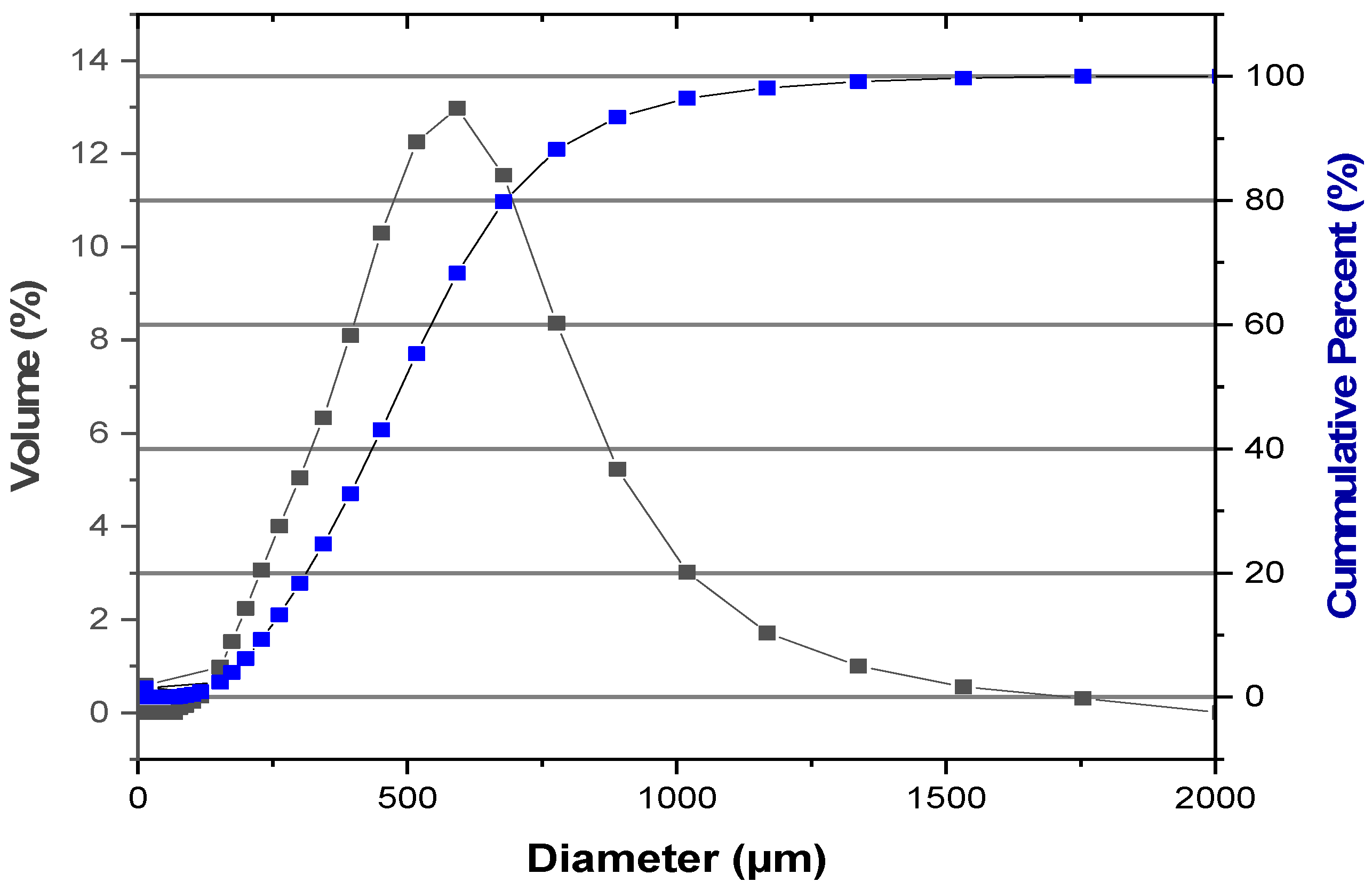
The sand particles of the desert region of Ouargla have wide particle size distribution. For that, using several sieves of different sizes and a vibratory sieve shaker, a sorting was carried out to keep only the particles of size between 250 and 850 µm (Table 3). The particle size distribution of the sand used is determined by a laser particle size analyzer, and the results are presented in Figure 3.
Then, the samples were sandblasted and characterized. The surface roughness of the central area of the sample was characterized before and after sandblasting with a profilometry instrument (Form Talysurf Series 120i by Taylor Hobson Company, Leicester, UK). The Ra roughness parameter (Equation (2)) is universally recognized, and it is the most used roughness parameter, defined as the arithmetic average of the absolute values of the Z(x) ordinates within a base length. As well, Z(x) is the function which describes the profile of the analyzed surface in terms of height (Z) and position (x) of the sample over an evaluation length “l”.
R a = 0 l 0 Z i x d x
The morphology of the coated surface was observed by atomic force microscopy (Asylum MFP3D, Oxford Instruments Asylum Research, Santa Barbara, CA, USA).

2.1.5. Coating of Sintered Samples

Silica-zirconia (SiO2-ZrO2) films were prepared by the hydrolysis and condensation of tetraethoxysilane (TEOS, Si(OC2H5)4, Sigma-Aldrich, Darmstadt, Germany, 99%), methyltriethoxysilane (MTES, CH3Si(OC2H5)3) (Sigma-Aldrich, 98%) and zirconium n-butoxide (ZrBu) as precursors. The sol was prepared in two steps; TEOS and MTES were first pre-hydrolyzed with acidified water (0.1 N HCl) for 2 hours at 40 °C. The molar ratios used were MTES/TEOS = 20/80. In a second step, ZrBu was mixed with acetylacetone in a molar ratio of ZrBu/AcAc = 1 and stirred for one hour. Then, distilled water was added while maintaining agitation for 1 h at 25 °C. Once both solutions were obtained, they were slowly mixed, and after 15 minutes, the remaining water was added dropwise (H2O/(TEOS + MTES + ZrBu) = 1.1) until the completion of hydrolysis, and the mixture was kept for 2 hours at 40 °C. The molar composition used is SiO2/ZrO2 = 95/05. The final concentration of (SiO2-ZrO2) was fixed to 130 g/L.
SiO2-ZrO2 sol was analyzed by an infrared spectrophotometer to monitor the hydrolysis and condensation reactions that occurred during the solution preparation. Figure 4 presents the FTIR transmittance spectra in the range of 4000–400 cm−1 of the silica-zirconia sol. The three dominant peaks characteristic of the Si-O were mentioned: The band at near to 1070 cm−1 is attributed to antisymmetric stretching of the oxygen atoms in the bond of Si-O-Si. The frequency peak below 450 cm−1 is attributed to the oscillatory movements of oxygen atoms perpendicular to the Si-O-Si plane or deformation vibrations of O-Si-O. The band at frequency near 878 cm−1 is associated with the symmetric stretching motion of oxygen atoms. These peaks confirm the hydrolysis reaction of the silica precursors and the formation of the Si-O-Si bond. The bands at 1262 cm−1 and 2900–3000 cm−1 are assigned to the Si-CH3 bonds.
The various bands observed in the infrared spectroscopy curve are summarized in Table 4.
According to Gonçalves et al. [32], the band located at around 940 cm−1 can be attributed to Si-O-Zr or Si-OH. The emergence of this band indicates the incorporation of zirconia into the silica network.
It is important to note that the solution stability is crucial to prevent poor deposition on the sample, thus the viscosity of the solution was measured using a vibro-viscosimeter SV-1A (A&D Company, Tokyo, Japan), and a value of 3. 71 mPa·s was obtained.
SiO2-ZrO2 sol was deposited on transparent spinel substrates by the dip-coating method. The samples were carefully cleaned with water and detergent and rinsed with distilled water and finally with ethanol in an ultrasonic bath, followed by drying. The deposition layer was carried out at a constant withdrawal rate of 3 cm/min.
After deposition, the obtained samples were heat treated in a furnace at 900 °C for 1 h to eliminate organic residues, densify the layer and impart final properties to the deposited layer. Typically, treatment of layers deposited on fragile materials such as glasses is carried out at temperatures below 500 °C. However, in our case, the layer was treated at 900 °C, which is likely to provide the deposited layer with very interesting optical and especially mechanical properties. This treatment helps to reduce the porosity by eliminating open pores and reducing pore size [34]. The deposited layer has an average thickness of 250 nm, measured by a mechanical profilometry.

3. Results and Discussion

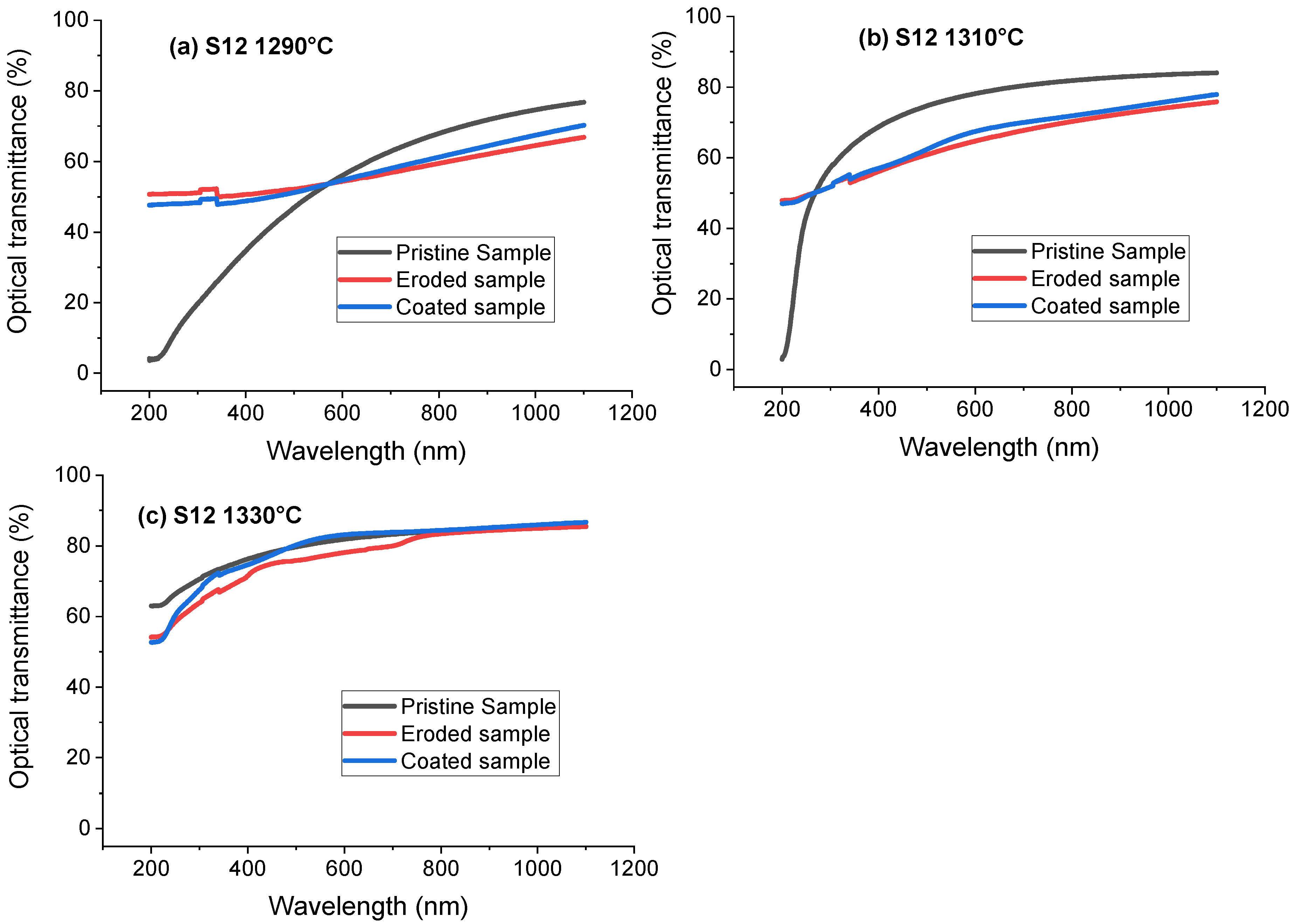
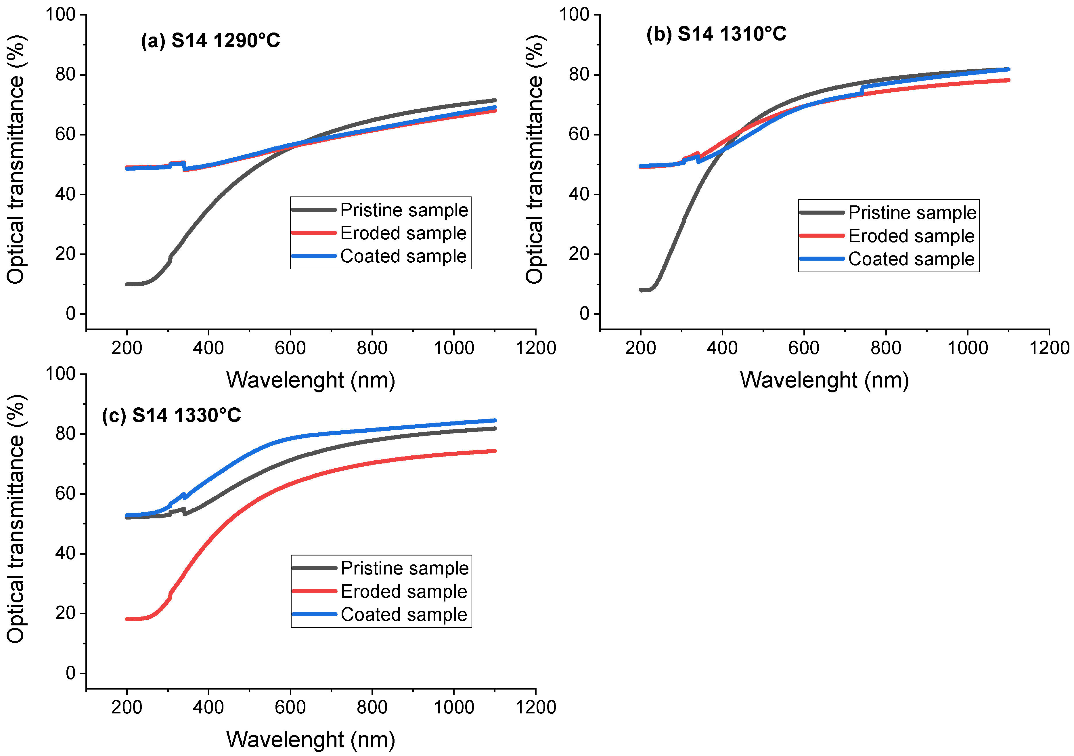
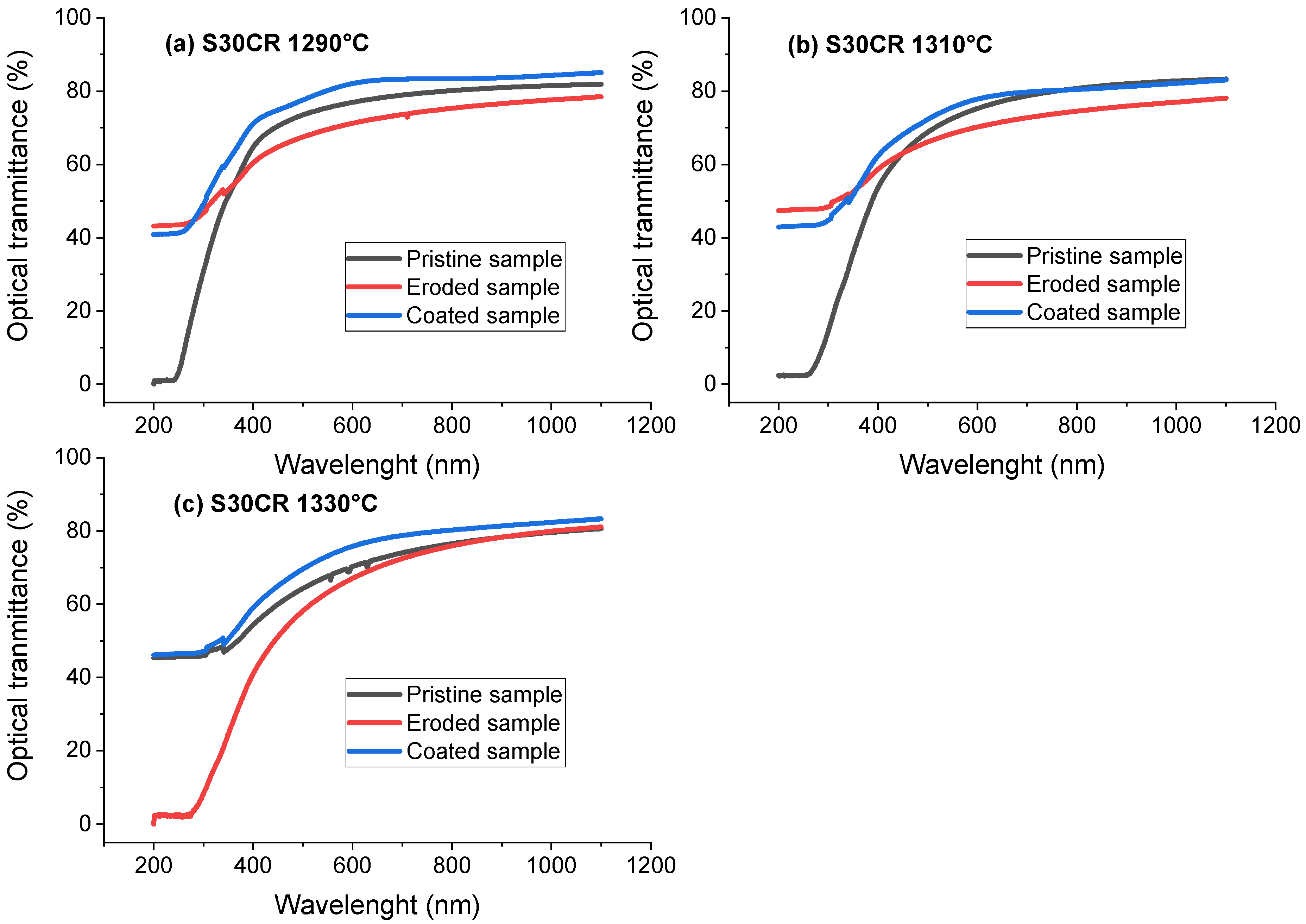
The spinel samples before and after being sandblasted and then after the deposition of SiO2-ZrO2 coatings were characterized by a UV-visible spectrophotometer. Figure 5, Figure 6 and Figure 7 show the UV-vis spectra between 200 and 1100 nm for the S25CRX12, S25CRX14 and S30CR spinel samples sintered at different temperatures before and after sandblasting and after the deposition of a SiO2-ZrO2 coating.
Figure 5 shows the evolution of optical transmission for S25CRX12 samples sintered at 1290, 1310 and 1330 °C. The optical transmission depends on the sintering temperature. In the pristine state at 200 nm, samples sintered at lower temperatures exhibit very low optical transmission, whereas the transmittance becomes important after sintering at 1330 °C. The increase in sintering temperature leads to an increase in optical transmission at 550 nm wavelength. It varies from 51.8 to 80.9% when the sintering temperature varies from 1290 to 1330 °C. At 1000 nm, similar effects were observed.
Concerning the damaged samples, at 200 nm, it is important to note that sandblasting increases the optical transmission of the fabricated spinel samples by approximately 40%, excepting for the sample sintered at 1330 °C, where sandblasting did not produce a great effect. Sandblasting has no significant effect on the optical transmission at 550 nm wavelength for the sintered samples, whatever the sintering temperature. At 1000 nm, sandblasting also degraded slightly the optical transmission of the samples, except for the sintering at 1330 °C.
After deposition of the coating layer, very small changes in optical properties are observed for 200, 500 and 1000 nm wavelengths; just a slight increase in the transmittance can be noted.
Figure 6 shows the UV-vis spectra for the S25CRX14 samples sintered at 1290, 1310 and 1330 °C before and after sandblasting and after the deposition of SiO2-ZrO2 coating. It is obvious that for the pristine state, increasing the sintering temperature increases the optical transmission of the spinel samples in the visible range at 550 nm wavelength. At 200 nm wavelength, the optical transmission for the pristine state is very low for the sintering at 1290 and 1310 °C, and for the sintering at 1330 °C, a relatively higher optical transmittance is noted. At 1000 nm wavelength, there is also an increase in optical transmission while increasing the sintering temperature.
Sandblasting of the spinel samples has an effect on the optical transmission of the S25CRX14 samples. Indeed, at 550 nm wavelength, sandblasting has slightly damaged the surface reflected by the reduction in the optical transmission values from 70 to 67 and from 69 to 60% for the sintering temperatures 1310 and 1330 °C, respectively. At 200 nm wavelength, the optical transmission is increased from 10 to 49%, and from 8 to 49% for the sintering temperatures 1290 and 1310 °C, respectively. For the sintering at 1330 °C, the optical transmission is reduced from 52 to 18%. Then, at 1000 nm wavelength, sandblasting reduces slightly the optical transmission for all the samples.
After deposition of the layer on the spinel samples, a clear improvement in the optical transmission at 550 nm wavelength of the sample sintered at 1310 °C is observed. At 550 nm wavelength, it can be noted that the coating has little effect on the transmission for the sintering at 1290 and 1310 °C, and an improvement in the optical transmission is observed for the sample sintered at 1330 °C. We also notice that at 200 nm wavelength, by applying the coating, an improvement in the optical transmission of the sandblasted sample sintered at 1330 °C is achieved from 18 to 53%. On the other hand, the coating has little effect on samples sintered at 1290 and 1310 °C. At 1000 nm wavelength, we can consider that the coating improves optical transmission, especially for samples sintered at 1310 and 1330 °C. The transmission varies from 73% after sandblasting to 84% after coating for the sample sintered at 1330 °C.
Figure 7 represents the variation of the optical transmission as a function of the wavelength of the S30CR samples sintered at 1290, 1310 and 1330 °C, respectively. In the pristine state, the samples exhibit at 200 nm wavelength a low optical transmission for the two sintering temperatures 1290 °C and 1310 °C and a relatively high transmission for the sintering at 1330 °C. At 1000 nm wavelength, all samples have high transmittance values up to 83%.
For the 200 nm wavelength, sandblasting has a considerable effect on the recorded values. For the sintering temperatures 1290 °C and 1310 °C, sandblasting increases significantly the optical transmission, whereas for the sintering temperature 1330 °C, the opposite effect is observed, with a significant reduction in the transmission. At 550 and 1000 nm wavelengths, sandblasting affected optical transmission by reducing slightly the optical properties.
Finally, after coating of the samples, we note a clear improvement in the optical transmission at 200 nm wavelength for the samples sintered at 1330 °C and a small effect for the sintering temperatures 1290 °C and 1310 °C. At 550 and 1000 nm, the coating increases slightly the transmission for all the sintering temperatures. Also, it is interesting to note that the transmission values after coating even exceed the initial values in the pristine state (see Table 5, Table 6 and Table 7).
The optical transmission values recorded at 200, 550 and 1000 nm for the S25CRX12, S25CRX14 and S30CR samples sintered at 1290, 1310 and 1330 °C are summarized in Table 5, Table 6 and Table 7.
From the results, it is possible to conclude that the transmission in the visible range depends significantly on the sintering temperature. The optical transmission presents the best values in the pristine state for the S25CRX12 powder, followed by the S30CR and the S25CRX14. Grain size measurements indicate that all samples present a small grain size ranging from approximately 300 to 900 nm (Table 2). It can also be noted that increasing the sintering temperature leads to the formation of larger grains for all the powders. Therefore, it appears that the good optical transmission depends neither on grain size nor on the surface area of the starting powders because the best performing sample, S25CRX12, has the lowest specific surface area (17.1 m2/g) and a relatively large grain size (835 nm). These interesting results can be attributed to the significant higher purity of this powder (S25CRX12) and, in particular, to the low sulfur content mentioned previously (Table 1). S25CRX14 contains a pore volume greater than the other two powders, with this powder exhibiting a lower compressibility [9]. The fine pores are especially located near the multiple grain junctions with a mean size of about 100 nm.
It can be noted that at 200 nm wavelength, the sandblasting tends to improve the transmission of spinel samples when the pristine transmission is low, which corresponds to some healing of small defects responsible for transmission, such as pores or flaws. Studies have shown that sensitivity to small defects is greater at low wavelengths. On the other hand, when the initial optical transmission is high for short wavelengths, the sandblasting of samples provokes a significant decrease in the transmission. For high wavelengths, the effect of sandblasting on the degradation of the optical transmission is lower. This can be attributed to the formation of large defects like chipping, as indicated by several studies [35] which report that after sandblasting transparent samples such as glasses or transparent ceramics, material removal takes place by formation and propagation of lateral cracks which develop into chipping. Evenly, increasing surface reflection can also be a contributing factor to the decrease in optical transmission [26]. Table 8 presents the roughness values Ra of the spinel samples in the pristine, sandblasted and then coated states.
Sandblasting degrades the surface of the samples, starting with a roughness Ra of around 8 nm in the pristine state to a higher roughness around 25 nm after sandblasting, which clearly affects the optical transmission of the material in most spectra, although, at 200 nm, there is a healing phenomenon, and the transmission increases. The transmission increases after sandblasting when the initial transmission is low, indicating a healing phenomenon.
The coating increases the optical transmission after sandblasting for all the wavelengths. This increase is very significant at 200 nm when the transmission after sandblasting is very low. The roughness values decrease after the deposition of the coating. On S30CR samples sintered at 1290, 1310 and 1330 °C and the S25CRX12 sample sintered at 1310 °C, the roughness Ra has lower values than in the pristine state, proving the effectiveness of the deposited layer in restoring the characteristics of an eroded material.
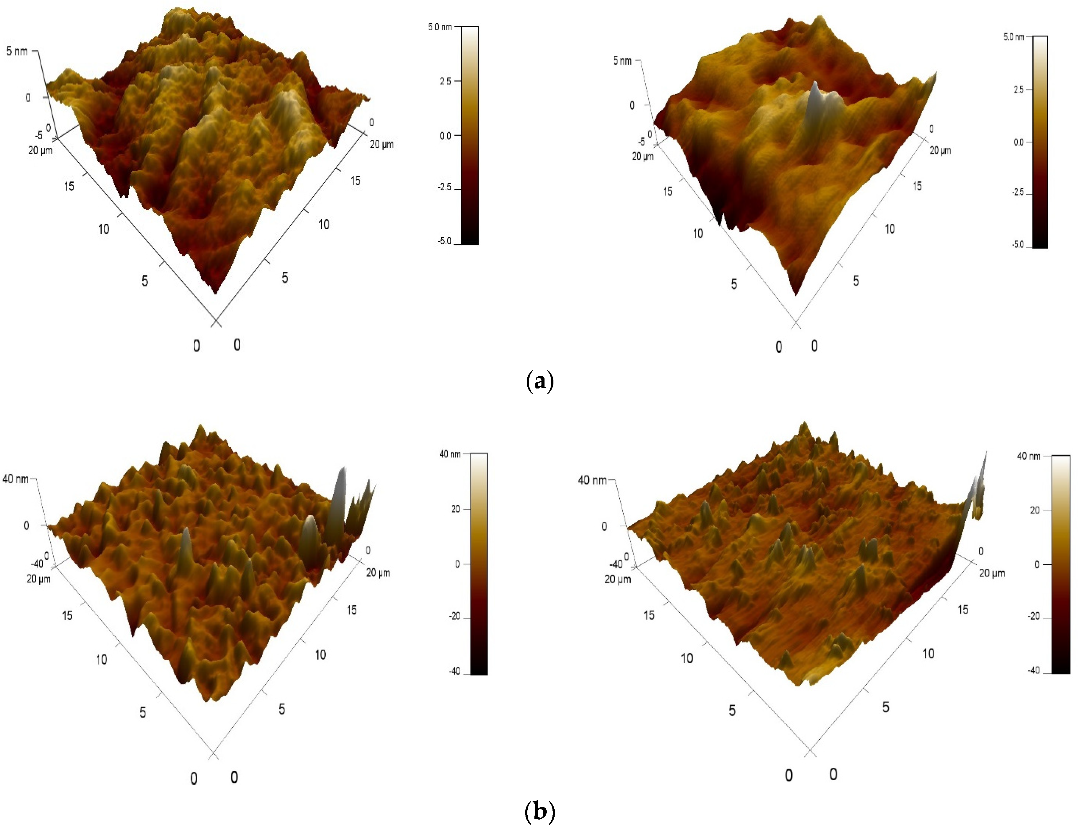
On S25CRX12 powder sintered at 1330 °C, and at a low wavelength of 200 nm, the coating improves the optical transmission lost during sandblasting. However, if sandblasting increases transmission (for the sintering temperatures 1290 and 1310 °C), the coating effect becomes very small to negligible. For the same wavelengths and for the S25CRX14 and S30CR powders, we have a behavior similar to that just shown. Then, at visible wavelengths, i.e., 550 nm, the S25CRX12 powder exhibits surface degradation, which implies a reduction in the optical transmission of the samples sintered at 1310 and 1330 °C. The same effect is observed on the S25CRX14 sample sintered at 1330 °C; otherwise, on the other samples, the effect of the coating is almost unremarkable. In the case of S30CR powder, all samples, regardless of their sintering temperature, are affected by sandblasting. Then, their optical properties are restored after coating. We can say that by applying a silica-based coating, the initial characteristics of the eroded spinel samples are largely restored, namely roughness and optical transmission. Indeed, sol-gel coatings can penetrate into the micro-defects and defects generated during sandblasting by filling them, adding an improvement in the morphology of the non-eroded zone. Previous results have shown that the coating heals defects in the pristine surface, thereby decreasing light reflection [26]. To better explain the restoration of surface roughness, an atomic force microscopy study was carried out. Figure 8 shows the variation in the roughness profile after sandblasting for the S25CRX14 and S30CR samples and then after coating.
From the microscopic images, it is clear that the surface roughness degraded by sandblasting is much improved after coating. This results in the filling of defects resulting from sandblasting, leading to a reduction in reflection and consequently an increase in optical transmission. Thus, the coating can restore optical properties and even exceed the transmission values recorded for the pristine sample. This is observed on samples of S25CRX 12 powders sintered at 1330 °C, S25CRX14 sintered at 1330 °C and on S30CR sintered at 1290 °C (Figure 9). This behavior can be linked to a decrease in the effect of sharp-bump defects, which became more spherical, as observed by Ayadi et al. [26] for glasses. It should be useful to make some SEM observations in order to specify this point. On the other hand, roughness alone is not sufficient to explain the results. Sandblasting can also increase the optical transmission of a spinel sample at short wavelengths thanks to a phenomenon of a defect’s healing such as pores or flaws.
At long wavelengths (1000 nm), the sintered S25CRX12 powder shows a degradation of the optical properties after sandblasting then a restoration of these properties after coating, except for the samples where sandblasting has no effect on the pristine state; then, a minimal effect can be cited. The same phenomenon was recorded on the S25CRX14 and S30CR powders, where there is no effect of the coating when sandblasting does not degrade the surface or optical transmission. On the other hand, when the sandblasting provokes a strong reduction in optical transmission, a significant improvement after coating is observed.
For the future, it would be interesting to investigate the damage caused on the surfaces eroded by sandblasting and the coating effect by making some microscopic observations with an optical or a scanning electronic microscope. Furthermore, it would be suitable to consider the two other alternative scenarios:
-
A sandblasted and coated sample is again exposed to sandblasting; thus, the optical endurance of the repaired ceramic can be determined.
-
A pristine sample is directly coated and characterized without sandblasting: what is the potential of such treatment and how it will perform when sandblasting.

4. Conclusions

Sand erosion of a transparent spinel fabricated with different powders (S25CRX12, S25CRX14, S30CR) sintered at different temperatures (1290, 1310, 1330 °C) was carried out, simulating the harsh conditions of a sandstorm in the Sahara. Then, a SiO2-ZrO2 layer deposition was carried out after sandblasting in order to correct the damage of the eroded surface. The results obtained allowed us to conclude with the following points:
  • In the pristine state, the optical transmission presents the best transmission values (85% at 1000 nm) for the S25CRX12 powder, followed by the S30CR then the S25CRX14. This good result can be attributed to the significant difference which lies in the high purity of this powder, particularly the sulfur content.
  • At 200 nm wavelength, sandblasting tends to improve the transmission of spinel samples (nearly 40%) for the specimens exhibiting a low transmission in the pristine state. This behavior can be attributed to the healing of small superficial defects responsible for the degradation of transmission, such as pores or flaws, for instance. Evenly, when the pristine transmission at 200 nm is high, the sandblasting worsens the transmission, which can be due to the formation of impact flaws.
  • Sandblasting reduces slightly the transmission values for long wavelengths due to the formation of large superficial defects like chipping by creation and propagation of lateral cracks. Furthermore, sandblasting degrades the surface of the samples, starting with a roughness Ra of around 8 nm in the pristine state to a significant roughness after sandblasting around 25 nm.
  • Using a silica-based coating can largely restore the initial roughness and optical transmission of the eroded spinel samples by repairing the superficial defects and filling flaws or cracks tips. After coating, the optical transmission is restored, and sometimes it is higher than the initial value.

Author Contributions

Conceptualization, A.Z. and A.A.; methodology, A.Z., A.A. and G.F.; validation, A.Z., A.A., M.H., A.D., Y.C. and G.F.; formal analysis, A.Z., M.H., A.D., Y.C. and G.F.; writing—original draft preparation, A.Z., A.A., I.K. and G.F.; writing—review and editing, A.Z., A.A., I.K., A. D., Y.C. and G.F.; visualization, A.Z., A.A., I.K. and G.F.; supervision, A.Z., M.H. and G.F. All authors have read and agreed to the published version of the manuscript.

Funding

The research received no external funding.

Data Availability Statement

The original contributions presented in the study are included in the article, further inquiries can be directed to the corresponding author.

Acknowledgments

The authors are grateful to L. Bonneau and A. Vivet from Baikowski (La Balme de Sillingy, France) for the supplying of the spinel powders.

Conflicts of Interest

The authors declare no conflicts of interest. Baikowski, the supplier of the spinel powders, had no role in the design, execution, interpretation, or writing of the study.

References

  1. Telling, R.H.; Jilbert, G.H.; Field, J.E. Erosion of aerospace materials by solid-particle impact. In Proceedings Volume 3060, Window and Dome Technologies and Materials V; SPIE: Bellingham, WA, USA, 1997. [Google Scholar] [CrossRef]
  2. Lallemant, L.; Garnier, V.; Bonnefont, G.; Marouani, A.; Fantozzi, G.; Bouaouadja, N. Effect of solid particle impact on light transmission of transparent ceramics: Role of the microstructure. Opt. Mater. 2014, 37, 352–357. [Google Scholar] [CrossRef]
  3. DiGiovanni Anthony, A.; Fehrenbacher, L.; Roy, D.W. Hard transparent domes and windows from magnesium aluminate spinel. In Proceedings Volume 5786, Window and Dome Technologies and Materials IX; SPIE: Bellingham, WA, USA, 2005. [Google Scholar] [CrossRef]
  4. Von Helden, S.; Malzbender, J.; Krüger, M. Mechanical properties, wear resistance and surface damage of glasses and MgAl2O4 spinel ceramic after abrasion and scratch exposure. Ceram. Int. 2019, 45, 10765–10775. [Google Scholar] [CrossRef]
  5. Lindsley, B.A.; Marder, A.R. The effect of velocity on the solid particle erosion rate of alloys. Wear 1999, 225–229, 510–516. [Google Scholar] [CrossRef]
  6. Wellman, R.G.; Allen, C. The effects of angle of impact and material properties on the erosion rates of ceramics. Wear 1995, 186–187, 117–122. [Google Scholar] [CrossRef]
  7. Krell, A.; Klimke, J.; Hutzler, T. Advanced spinel and sub-μm Al2O3 for transparent armor applications. J. Eur. Ceram. Soc. 2009, 29, 275–281. [Google Scholar] [CrossRef]
  8. Tokariev, O.; Schnetter, L.; Beck, T.; Malzbender, J. Grain size effect on the mechanical properties of transparent spinel ceramics. J. Eur. Ceram. Soc. 2013, 33, 749–757. [Google Scholar] [CrossRef]
  9. Zegadi, A.; Kolli, M.; Hamidouche, M.; Fantozzi, G. Transparent MgAl2O4 spinel fabricated by spark plasma sintering from commercial powders. Ceram. Int. 2018, 44, 18828–18835. [Google Scholar] [CrossRef]
  10. Swab, J.J.; Pavlacka, R.; Gilde, G.; Kilczewski, S.; Wright, J.; Harris, D. Determining the Strength of Coarse-Grained ALON and Spinel. J. Am. Ceram. Soc. 2014, 97, 592–600. [Google Scholar] [CrossRef]
  11. Tustison, R.W. Window and Dome Technologies and Materials XI. Orlando, Florida, United States. Proceedings of SPIE, 7302; SPIE: Bellingham, WA, USA, 2009. [Google Scholar]
  12. Pellice, S.; Gilabert, U.; Solier, C.; Castro, Y.; Durán, A. Mechanical behavior of glass reinforced with SiO2 hybrid sol–gel coatings. J. Non-Cryst. Solids 2004, 348, 172–179. [Google Scholar] [CrossRef]
  13. Gallardo, J.; Durán, A.; Di Martino, D.; Almeida, R.M. Structure of inorganic and hybrid SiO2 sol–gel coatings studied by variable incidence infrared spectroscopy. J. Non-Cryst. Solids 2002, 298, 219–225. [Google Scholar] [CrossRef]
  14. Innocenzi, P.; Abdirashid, M.O.; Guglielmi, M. Structure and properties of sol-gel coatings from methyltriethoxysilane and tetraethoxysilane. J. Sol-Gel Sci. Technol. 1994, 3, 47–55. [Google Scholar] [CrossRef]
  15. García-Heras, M.; Rincón, J.M.; Romero, M.; Villegas, M.A. Indentation properties of ZrO2–SiO2 coatings on glass substrates. Mater. Res. Bull. 2003, 38, 1635–1644. [Google Scholar] [CrossRef]
  16. Endres, K.; Mennig, M.; Amlung, M.; Gier, A.; Schmidt, H. Enhancement of fracture strength of cutted plate glass by the application of SiO2 sol-gel coatings. Thin Sol. Films 1999, 351, 132–136. [Google Scholar] [CrossRef]
  17. Zhang, Q.; Li, X.; Shen, J.; Wu, G.; Wang, J.; Chen, L. ZrO2 thin films and ZrO2-SiO2 optical reflection filters deposited by sol–gel method. Mat. Lett. 2000, 45, 311–314. [Google Scholar] [CrossRef]
  18. Zhang, H.; Zhou, J.-H.; Zhang, Q.-L.; Yang, H. Mechanical and Optical Properties of Ion-exchange Strengthened Glass Coated with Sol-Gel Derived ZrO2-SiO2 Film. J. Inorg. Mater. 2013, 28, 779–785. [Google Scholar] [CrossRef]
  19. Ma, K.J.; Chien, H.H.; Huang, S.W.; Chen, S.C.; Chao, C.L. Crack Filling of Cover Glasses by Sol-Gel Coatings. Adv. Mater. 2013, 797, 700–705. [Google Scholar] [CrossRef]
  20. Nogami, M. Glass preparation of the ZrO2-SiO2 system by the sol-gel process from metal alkoxides. J. Non-Crys Solids 1985, 69, 415–423. [Google Scholar] [CrossRef]
  21. Bonnefont, G.; Fantozzi, G.; Trombert, S.; Bonneau, L. Fine-grained transparent MgAl2O4 spinel obtained by spark plasma sintering of commercially available nano powders. Ceram. Int. 2012, 38, 131–140. [Google Scholar] [CrossRef]
  22. Apetz, R.; Van Bruggen, M.P.B. Transparent Alumina: A Light-Scattering Model. J. Am. Ceram. Soc. 2003, 86, 480–486. [Google Scholar] [CrossRef]
  23. DIN 50332; Strahlverschleiβprufung (Ray of Schleiβ Test). DIN: Berlin, Germany, 1984.
  24. ASTM G76-04; Standard Test Method for Conducting Erosion Tests by Solid Particle Impingement Using Gas Jets. ASTM International: West Conshohocken, PA, USA, 2004.
  25. Oka, Y.I.; Mihara, S.; Yoshida, T. Impact-angle dependence and estimation of erosion damage to ceramic materials caused by solid particle impact. Wear 2009, 267, 129–135. [Google Scholar] [CrossRef]
  26. Ayadi, A.; Bouaouadja, N.; Durán, A.; Castro, Y. Hybrid SiO2–ZrO2 coatings for restoring and repairing glasses damaged by sandblasting. Ceram. Int. 2020, 46, 10634–10640. [Google Scholar] [CrossRef]
  27. Brinker, C.J.; Scherer, G.W. Sol-Gel Science, The Physics and Chemistry of Sol-Gel Processing; Academic Press: Cambridge, MA, USA, 1990; 463p, ISBN 13:978-0-12-134970-7. [Google Scholar]
  28. Al-Oweini, R.; El-Rassy, H. Synthesis and characterization by FTIR spectroscopy of silica aerogels prepared using several Si(OR)4 and R″Si(OR′)3 precursors. J. Mol. Struct 2009, 919, 140–145. [Google Scholar] [CrossRef]
  29. Gopal, N.O.; Narasimhulu, K.V.; Rao, J.L. EPR, optical, infrared and Raman spectral studies of Actinolite mineral. Spectrochim. Acta. Mol. Biomol. Spectrosc. 2004, 60, 2441–2448. [Google Scholar] [CrossRef] [PubMed]
  30. Bertoluzza, A.; Fagnano, C.; Antonietta Morelli, M.; Gottardi, V.; Guglielmi, M. Raman and infrared spectra on silica gel evolving toward glass. J. Non-Cryst. Solids 1982, 48, 117–128. [Google Scholar] [CrossRef]
  31. Socrates, G. Infrared and Raman Characteristic Group Frequencies: Tables and Charts, 3rd ed.; Wiley: Abingdon, UK, 2004; 368p, ISBN 978-0-470-09307-8. [Google Scholar]
  32. Gonçalves, R.R.; Guimarães, J.J.; Ferrari, J.L.; Maia, L.J.Q.; Ribeiro, S.J.L. Active planar waveguides based on sol–gel Er3+-doped SiO2–ZrO2 for photonic applications: Morphological, structural and optical properties. J. Non-Cryst. Solids 2008, 354, 4846–4851. [Google Scholar] [CrossRef]
  33. Chmel, A. Vibrational spectra and defect structure of silica prepared by non-organic sol-gel process. J. Non-Cryst. Solids 1990, 122, 285–290. [Google Scholar] [CrossRef]
  34. Sakka, S. Handbook of Sol-Gel Science and Technology: Processing, Characterization and Applications, Volume I: Sol-Gel Processing; Kluwer Academic Publishers: Boston, MA, USA; Springer Science and Business Media: New York, NY, USA, 2005; 680p, ISBN 1402079664/9781402079665. [Google Scholar]
  35. Ćurković, L.; Kumić, I.; Grilec, K. Solid particle erosion behavior of high purity alumina ceramics. Ceram. Int. 2011, 37, 29–35. [Google Scholar] [CrossRef]
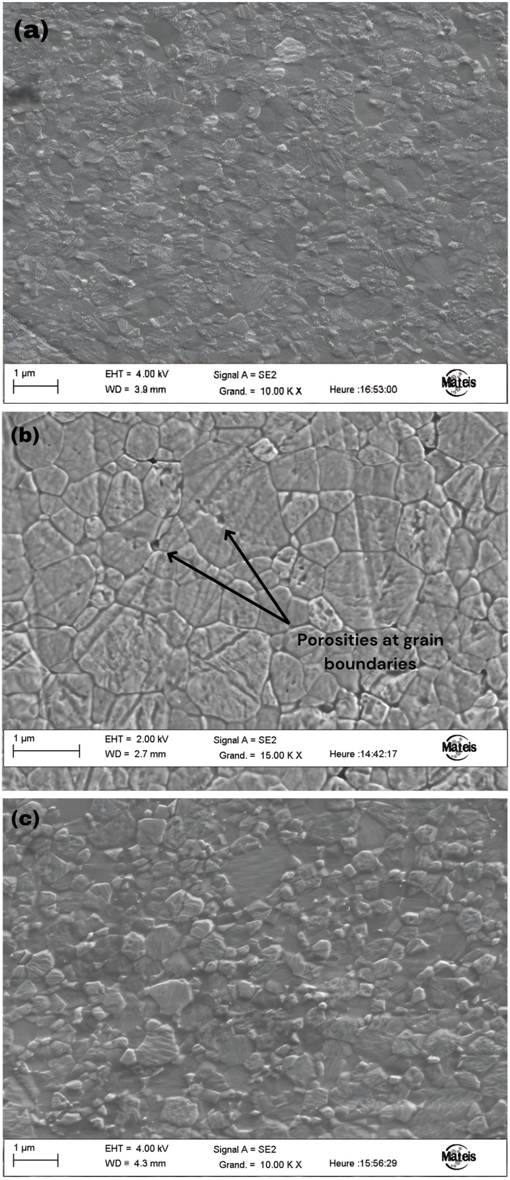
Figure 1. SEM images of samples (a) S25CRX12, (b) S25CRX14 and (c) S30CR sintered at 1310 °C.
Ceramics 07 00049 g001
Figure 2. Micrograph of used sand particles from the desert region of Ouargla.
Ceramics 07 00049 g002
Figure 3. Particle size distribution of the used sand.
Ceramics 07 00049 g003
Figure 4. Infrared spectrum of the SiO2-ZrO2 solution.
Ceramics 07 00049 g004
Figure 5. Evolution of optical transmission before and after sandblasting, then after coating of S25CRX12 spinel samples sintered at 1290, 1310 and 1330 °C.
Ceramics 07 00049 g005
Figure 6. Evolution of optical transmission before and after sandblasting then after coating of S25CRX14 spinel samples sintered at 1290, 1310 and 1330 °C.
Ceramics 07 00049 g006
Figure 7. Evolution of optical transmission before and after sandblasting then after coating of S30CR spinel samples sintered at 1290, 1310 and 1330 °C.
Ceramics 07 00049 g007
Figure 8. Surface roughness after sandblasting and after coating for samples; left: uncoated, right: coated. (a) S25CRX14 sintered at 1310 °C, (b) S30CR sintered at 1310 °C.
Ceramics 07 00049 g008
Figure 9. Best optical transmission values obtained after coating.
Ceramics 07 00049 g009
Table 1. Average chemical composition (in ppm by weight) of the used powders (for the S25CRX12 and S25CRX14 powders, the abbreviated names S 12 and S 14 are used).
Chemical Composition Weight
(ppm)
Crystallite Size (nm)SSA (m2/g)
NaKFeSiCaS
S 1211148.1134.32002917.1
S 1411136.5146.93006027.4
S30CR1335136<16007331
Table 2. Grain size (nm) for the S25CRX12, S25CRX14 and S30CR samples sintered at 1290 °C, 1310 °C and 1330 °C by SPS.
Grain Size (nm)
Sintering temperature (°C)129013101330
S 12338500835
S 14366628805
S30CR408614964
Table 3. Sand particle size distribution parameters.
Diameter (D)Particles Size (µm)
D (0.1) minimum diameter235
D (0.5) average diameter515
D (0.9) maximum diameter815
Table 4. Different structures in the SiO2-ZrO2 solution depending on wave number.
Wave Number (cm−1)VibrationStructureReferences
13323Stretching O-H and Si-O-HH-O-H/H2O[27]
22973νs C-HSi-CH3/-CH3[28]
31262δs C-HSi-CH3[29]
41042νas Si-O-SiSi-O-Si[30]
5940νβ Si-O≡Si-OH
Si-O-Zr
[31]
[32]
6878νβ Si-OSi-O[33]
7432δ O-Si-OO-Si-O[30]
Vibration types: νs symmetric stretching vibration, νas antisymmetric stretching vibration, νβ in-plane stretching vibration, δ deformation vibration, δs symmetric deformation vibration (bending).
Table 5. Optical transmission values recorded at 200 nm for the S25CRX12, S25CRX14 and S30CR samples sintered at 1290, 1310 and 1330 °C.
Transmittance at λ = 200 nm
Sintering Temperature Pristine (%)Eroded (%)Coated (%)
S 12S 14S30CRS 12S 14S30CRS 12S 14S30CR
1290 °C4.210050.749.043.147.648.540.8
1310 °C2.88.12.4747.849.147.447.049.542.9
1330 °C62.952.145.3454.118.2052.652.846.1
Table 6. Optical transmission values recorded at 550 nm for the S25CRX12, S25CRX14 and S30CR samples sintered at 1290, 1310 and 1330 °C.
Transmittance at λ = 550 nm
Sintering TemperaturePristine (%)Eroded (%)Coated (%)
S 12S 14S30CRS 12S 14S30CRS 12S 14S30CR
1290 °C51.852.175.553.254.369.552.954.980.2
1310 °C76.670.272.662.967.468.465.266.675.6
1330 °C80.968.567.676.960.263.282.176.573.1
Table 7. Optical transmission values recorded at 1000 nm for the S25CRX12, S25CRX14 and S30CR samples sintered at 1290, 1310 and 1330 °C.
Transmittance at λ = 1000 nm
Sintering Temperature Pristine (%)Eroded (%)Coated (%)
S 12S 14S30CRS 12S 14S30CRS 12S 14S30CR
1290 °C74.669.781.464.565.977.667.466.284.3
1310 °C83.581.182.774.277.377.075.980.482.1
1330 °C85.280.979.584.973.479.98683.582.3
Table 8. Roughness Ra of spinel samples S25CRX12, S25CRX14 and S30CR before and after sandblasting and after coating.
Ra (nm)
Sintering Temperature PristineErodedCoated
S 12S 14S30CRS 12S 14S30CRS 12S 14S30CR
1290 °C6.34.68.61514.927.6126.75.7
1310 °C8.37.610.125.316.719.26.78.67
1330 °C6.45.51223.139.222.58.88.38.1
Disclaimer/Publisher’s Note: The statements, opinions and data contained in all publications are solely those of the individual author(s) and contributor(s) and not of MDPI and/or the editor(s). MDPI and/or the editor(s) disclaim responsibility for any injury to people or property resulting from any ideas, methods, instructions or products referred to in the content.