Review

A Review of Zirconolite Solid Solution Regimes for Plutonium and Candidate Neutron Absorbing Additives

by
Lewis R. Blackburn
1,*,
Claire L. Corkhill
1,2 and
Neil C. Hyatt
1,3
1
Immobilisation Science Laboratory, Department of Materials Science and Engineering, University of Sheffield, Sir Robert Hadfield Building, Mappin Street, Sheffield S1 3JD, UK
2
School of Earth Sciences, University of Bristol, Bristol BS8 1RJ, UK
3
School of Mechanical and Materials Engineering Program, Washington State University, Pullman, WA 99164, USA
*
Author to whom correspondence should be addressed.
Ceramics 2023, 6(3), 1330-1347; https://doi.org/10.3390/ceramics6030082
Submission received: 26 April 2023 / Revised: 12 June 2023 / Accepted: 16 June 2023 / Published: 22 June 2023
(This article belongs to the Special Issue Zirconolite Ceramic and Glass-Ceramic Wasteforms)

Abstract

:
Should the decision be made to immobilise the UK Pu inventory through a campaign of Hot Isostatic Pressing (HIP) in a zirconolite matrix, prior to placement in a geological disposal facility (GDF), a suite of disposability criteria must be satisfied. A GDF safety case should be able to demonstrate that post-closure criticality is not a significant concern by demonstrating that such an event would have a low likelihood of occurring and low consequence if it were to occur. In the case of ceramic wasteforms, an effective means of criticality control may be the co-incorporation of a requisite quantity of a suitable neutron absorbing additive, either through co-immobilisation within the host structure or the encapsulation of discrete particles within the grain structure. Following an initial screening of a range of potential neutron absorbing additives, a literature-based assessment of the solid solution limits of a number of potential additives (Gd, Hf, Sm, In, Cd, B) in the candidate zirconolite (CaZrTi2O7) wasteform is presented. Key areas of research that are in need of development to further support the safety case for nuclearised HIP for Pu inventories are discussed.

1. Status of the United Kingdom’s Plutonium Inventory

Upon completion of domestic reprocessing of spent nuclear fuel (SNF) derived from the civil reactor fleet, the United Kingdom will have accumulated a substantial inventory of separated PuO2 in excess of 140 teHM (tonnes heavy metal equivalent) [1,2]. This inventory is the result of the PUREX reprocessing (Plutonium Uranium Reduction Extraction) of SNF. In the PUREX process, irradiated fuel assemblies are discharged from a reactor, cooled, sheared and dissolved in HNO3, with Pu/U subsequently recovered in a series of solvent extraction steps. Pu(IV) and Pu(III) nitrates are coextracted from the aqueous raffinate by complexation with tributyl phosphate (TBP), followed by precipitation as Pu insoluble oxalates, Pu4+(C2O4)3·6H2O and Pu3+2(C2O4)3·10H2O, via the addition of oxalic acid. The precipitated oxalates are subsequently converted to PuO2 via calcination in the air or an inert atmosphere, with calcination temperature and time generally inversely proportional to specific surface area (m2/g), prior to interim storage awaiting a decision on long term management [3]. The Nuclear Decommissioning Authority (NDA) is responsible for identifying a preferred long term strategy for placing this material beyond reach, satisfying proliferation and safety concerns, that the site license companies will implement. Potential routes towards Pu recycling and/or disposal were defined in the Credible Options Analysis, utilising a life cycle approach to outline and evaluate: (1) pathways to disposition within the constraints of financial and socioeconomic benefit; (2) safety and compatibility with the disposal environment; and (3) readiness and maturity of necessary technology [4]. Several iterations of the Credible Options framework have identified two high level options that are feasible: reuse of the bulk inventory as mixed oxide fuels (MOX) or chemical immobilisation of the inventory in a suitable matrix. In either case, it is accepted that the timescales for the implementation of any strategy will be several decades at a minimum, and consideration must be given to the quality and source of the Pu feedstock. A summary of UK Pu stocks reported to IAEA under INFCIRC/549 is listed in Table 1. As of 2022, and outlined in the NDA 2022–2025 Business Plan, all separated Pu has been produced and consolidation at Sellafield has been completed. At this stage, a campaign of repacking for long term storage is underway, with all cans not suitable for extended storage undergoing repackaging. The merits of a MOX fuel-based strategy will not be discussed in this article, and the reader can be referred to the latest NDA Strategy and Position Paper (2019) [1]. Legacy storage of PuO2 inventories over the past ~60 y has resulted in a fraction of the inventory becoming contaminated with Cl; whilst it is envisaged that this contaminated material will still be suitable for reuse, there is a sizeable inventory of MOX scraps and unirradiated fuel assemblies that will not be suitable for reuse. Any Pu materials designated for disposal (both of high purity and contaminated status) will necessitate specifically tailored ceramic or glass–ceramic wasteforms for immobilisation prior to disposition within a geological disposal facility (GDF).

2. Criticality Safety and the Role of Neutron Absorbing Additives in Waste Packages

To construct a site specific safety case for the geological disposal of higher activity radioactive wastes in the UK, Nuclear Waste Services (NWS), a subsidiary of the NDA and the body responsible for the design, construction, and continued operation of the as yet un-sited GDF, maintains a generic disposal safety case outlining the claims, arguments, and evidence that underpin GDF deliverability. A key aspect of the safety case is an assessment of waste package criticality during transport, GDF operation, and post closure [6]. Generic Criticality Safety Assessments (CSAs), as described by Hicks (2007), are considered for waste packages containing one or more of the following four waste components: irradiated natural and slightly enriched uranium; low enriched uranium; high enriched uranium and; separated plutonium [7]. In the interest of brevity, this report will focus only on separated Pu. The reader is referred to Solano et al., (2012) for a comprehensive discussion of criticality control in intermediate level waste and SNF packages [8].
Criticality control measures guard against an inadvertent self-sustaining chain reaction within immobilised fissile material. During the construction and operational phase of the GDF, waste packages will be transported to the facility and placed in a suitable geometrical arrangement in pre-designated areas. The safety of workers and the general public must therefore be ensured by two general approaches: (1) producing waste packages that remain sub-critical by placing an upper limit on the quantity of fissile material contained within and; (2) by optimising the physical form of the waste package such that a critical chain reaction is not possible, either through an arrangement in specific dimensions and geometry that are capable of mitigating the accumulation and critical mass of fissile material, or through the addition of a neutron absorbing additive. The condition of criticality is met when radionuclides capable of undergoing fission are arranged such that a self-sustaining chain reaction may occur. This is described by the notation Keff = 1, i.e., the rate of neutrons produced by per fission and the rate of neutrons lost by absorption, or leakage, is equal to unity. Under this condition, a self-sustaining reaction will occur.
Following the closure of the GDF, criticality assurance may be provided through a series of engineered barriers, providing a layered defence known as the multi-barrier concept [9]; however, it is accepted that on the timescale of >103 years, water will slowly ingress, resulting in the deterioration of the physical containment of waste packages. The release of radioactive material into the near field is considered to be inevitable, with the possibility of new configurations that could result in criticality. An arrangement of material that is critical would likely produce an increase in temperature and result in the generation of fission products. A suitable additive for mitigating criticality has a high thermal neutron cross-section and may easily be integrated into a wasteform package to reduce the overall neutron flux, thus reducing Keff < 1 and mitigating the possibility of criticality. Inhibiting the neutron flux by the inclusion of additives may also afford the opportunity to increase the upper wasteloading limit, improving the volume footprint of the repository environment and reducing the number of waste packages, in turn reducing the number of handling operations and associated dose uptake to workers. There are a number of candidates that have been proposed as suitable additives for Pu-containing ceramics. For example, Nadykto and Timofeeva (2001) [10] estimated that in the case of thermal neutrons, the additive:Pu nuclei ratio to avoid a nuclear chain reaction for B, Gd, Cd, Sm, and Eu was 1.6, 0.023, 0.45, 0.2, and 0.25, respectively. The incorporation of the additive in the wasteform could be accomplished in a number of ways.
There is not currently a consensus regarding the most effective means or efficacy of adding the neutron absorbing additive to a wasteform on an industrial scale; however, the addition would likely have to be constrained within the batch formulation and powder preparation stage. The engineering unit operations for a HIP-based strategy are illustrated in Figure 1. Within this process, there are two options that may be suitable, as they do not require additional handling or unit operations associated with them and make use of existing pre-treatment parameters that are already essential to the HIP program. These are as follows:
(1) Wasteform tailoring—In this option, the ceramic composition is tailored such that a pre-determined quantity of additive can be incorporated within the structure without disrupting the phase assemblage or resulting in the formation of deleterious secondary phases. The addition of trivalent species, e.g., Gd3+, would necessitate tailoring of the nominal composition to account for excess/deficiency in charge units across the structure. An appropriate amount of additive is incorporated in the oxide form directly to the milling stage as a function of the total wt. % of the waste package (e.g., direct addition of 2 wt. % Gd2O3). The inactive component of the ceramic precursor would require a pre-treatment stage consisting of homogenisation and calcination prior to the addition of the PuO2. This would be followed by a secondary milling stage to ensure complete oxide dispersion and size reduction to assist the sintering process. In this case, the additive source may be introduced alongside the PuO2 at the secondary milling stage. Compositions developed for this route are discussed in detail in the following section.
(2) Additive encapsulation—Alternatively, the additive may be incorporated into the waste microstructure as discrete particles via encapsulation. This may be more applicable for additives such as boron which, due to its small ionic radius, may not be effectively accommodated in a solid solution with the host ceramic phase. In this instance, a compound such as B4C may be encapsulated at intergranular spaces and triple points, forming discrete particulates within the microstructure. An additive such as B4C has an extremely high Vickers hardness; therefore, to attain homogeneous distribution throughout the microstructure, the feed would have to be comprised of a fine powder that can easily be dispersed, or the process would need to take advantage of an aggressive milling stage.

3. Review of Zirconolite Chemistry and Evaluation of Potential Solid Solution Regimes for Pu Immobilisation
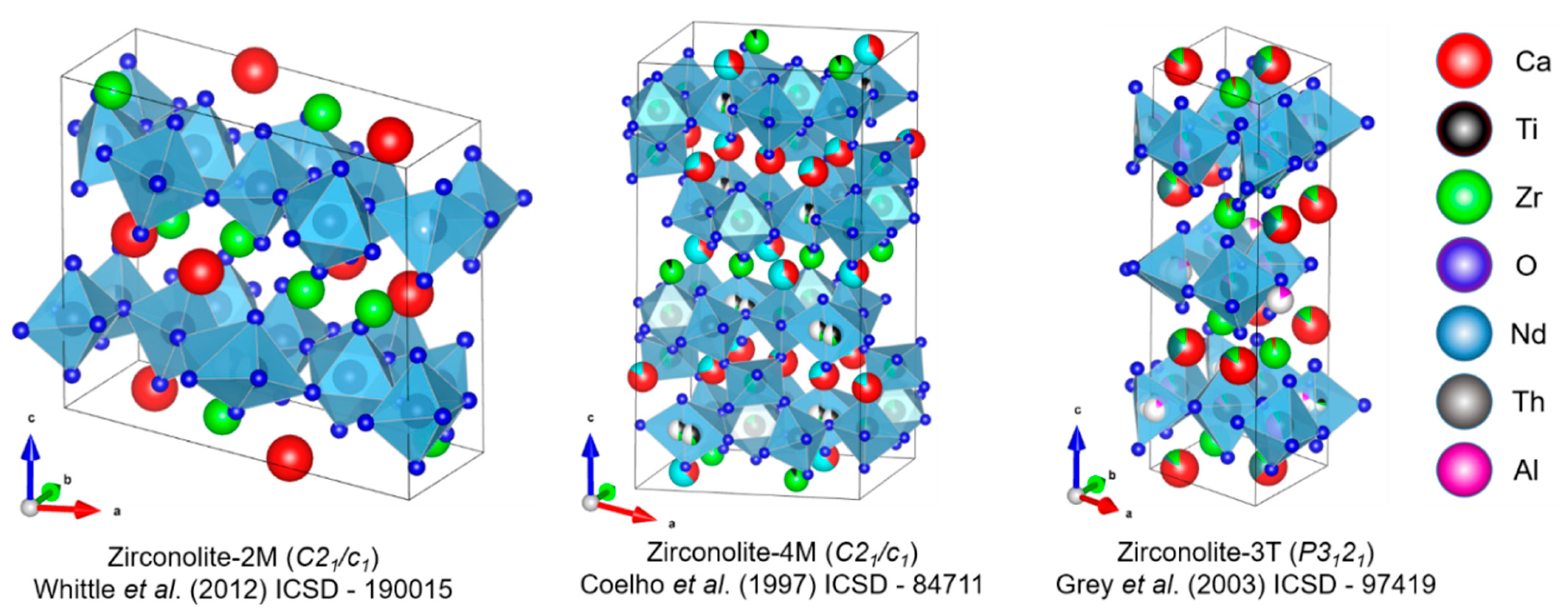
Technical efforts in the UK to identify a suitable wasteform for separated Pu have considered single and multiphase ceramics based on derivatives of the titanate pyrochlore-rich wasteform developed for the US DoE Plutonium Immobilisation Project (PIP) and vitrified wasteforms based on variations of borosilicate glass (e.g., lanthanide borosilicate (LaBS), alkali tin silicates (ATS)). Encapsulation and dilution of PuO2 in cementitious wasteforms is still also considered a technically feasible option on the basis of GDF compliance and simplicity [11,12]. Following several years of inactive trials and deselection, occurring primarily in collaboration between the National Nuclear Laboratory (NNL) and the Immobilisation Science Laboratory (ISL), wasteforms favouring zirconolite as the host Pu phase have been selected as the preferred candidate and, as such, a program of systematic active and inactive trials aiming to maximise Pu wasteloading through tailoring a selection of baseline compositions and further probe the underlying crystallography of the zirconolite structure is underway [13,14,15,16].
Zirconolite (nominally CaZrTi2O7) is a rare accessory mineral that is present in a wide variety of terrestrial localities, demonstrating an affinity for an extensive solid solution with, but not limited to, Mg2+, Al3+, Fe2+/3+, Nb5+, Ta5+, Pb2+, U4+, Th4+, Ce3+/4+, Pr3+, Gd3+, Sm3+, and Nd3+ [17]. The ability of zirconolite to incorporate such a wide variety of species, with five distinct cation receptor sites (CaVIII, ZrVII, Ti(I)VI, Ti(II)V, and Ti(III)VI), makes it an ideal candidate for co-immobilisation of separated Pu, lower valence charge compensator cations such as Mg2+ and Al3+, and an appropriate amount of a suitable neutron absorbing additive (e.g., Gd3+) to suppress criticality. Zirconolite (the archetype of which is the 2M structure) has been recognised by NDA as a candidate ceramic phase for Pu and, as such, has commissioned a body of work aiming to systematically validate potential solid solutions using a combination of surrogates (Ce/U/Th). It should also be noted that glass–ceramic wasteforms based on the CaZrTi2O7—Na2Al2Si6O16 system have also been proposed for Cl-contaminated Pu residues [18,19,20,21,22].
The idealised zirconolite parent structure crystallises in monoclinic symmetry (space group C2/c) and comprises two distinct cation layers, where Ca2+ and Zr4+ polyhedra are 8 and 7-fold coordinated to oxygen (i.e., CaO8 and ZrO7), respectively, and are interspaced by layers of Ti-O polyhedra arranged in a topology closely related to that of hexagonal tungsten bronze (HTB) (Figure 2). In this theoretical description, Ti occupies three distinct sites within the HTB layer, two of which are 6-fold coordinated to oxygen forming six-membered rings. The remaining Ti is statistically distributed in the centre of these rings, in a 50% occupied 5-fold coordinated trigonal bi-pyramidal site. In the zirconolite unit cell, planes of Ca/Zr polyhedra and HTB layers are stacked 1:1 along parallel to [001], with HTB positioned at z = 0.25 and z = 0.75 related by a 180° rotation, offset along [130]; subsequent modules at z = 0.75 and z = 1.25 are offset in the [1–30] direction [23]. This structure is referred to as zirconolite-2M, with reference to the two-layer repeating lamellar structure comprising the monoclinic unit cell. A more comprehensive description is provided by Gatehouse et al. in which the zirconolite-2M structure remains stable over the solid solution CaZrxTi3−xO7 constrained by 0.80 < x < 1.35 [24], with mixed occupancy of Zr-Ti-O polyhedra also determined to be a function of temperature, between 1350 and 1500 °C [25].
Zirconolite structured materials are typically produced via high temperature sintering from a mixture of oxide precursors, and although sintering regimes are typically >1300 °C and >10 h, there does not seem to be any clear correlation between processing conditions and lattice dimensions. A selection of reported lattice parameters of CaZrTi2O7 and corresponding processing conditions are listed in Table 2. Due to the flexibility of the zirconolite structure, a variety of potential solid solution regimes for Pu immobilisation have been identified, both from a survey of available literature and hypothesised based on feasible (charge balanced) substitutions (Table 3). Depending on the substitution mechanism and prevailing oxygen fugacity during the sintering process, zirconolite may crystallise in several distinct polytypes, characterised in principle by variation in the stacking sequence of Ca/Zr and HTB layers. For example, the incorporation of >0.15 f.u. of M4+ (Ce/U/Pu) promotes the formation of the zirconolite-4M polytype, described by Coelho et al. as a four layer intergrowth of zirconolite-2M and pyrochlore-type modules, resulting in a doubling of the zirconolite unit cell along the c* axis [23]. Zirconolite-4M may also form as a result of near equimolar accommodation of trivalent species within the Ca2+ and Zr4+ sites, i.e., zirconolite-4M is essentially an intermediate phase between CaZrTi2O7 (zirconolite) and REE3+2Ti2O7 (pyrochlore) end-members [28]. Heavily disordered substitution regimes, such as targeting accommodation of M3+ and M4+ species between Ca2+ and Ti4+ sites, may also result in the formation of other polytypes, such as zirconolite-3T (trigonal unit cell, space group: Pbnm) or zirconolite-3O (orthorhombic unit cell, space group: Acam). For a comprehensive discussion of zirconolite polytypism, the reader is referred to White (1984) [29]. Generally, substitution schemes for the accommodation of Pu4+ within the Ca2+ site are facilitated by a charge-coupled substitution, whereby a lower valence cation such as M = Fe3+/Al3+ is accommodated within the Ti4+ site [30]. As stated, a simple isovalent substitution for Zr4+ has also been demonstrated and may allow greater wasteloading; however, this results in a phase assemblage dominated by zirconolite-4M, using both Ce/U surrogates and Pu [16,31,32].
Table 2. Reported unit cell parameters for zirconolite polytypes.
StructureSymmetrya (Å)b (Å)c (Å)β (°)Space GroupOriginRef.
2MMonoclinic12.44357.273511.374810.563C2/cSynthetic[14]
4MMonoclinic12.5537.24823.08184.799C2/cSynthetic[23]
3TTrigonal7.228-16.805-P3121Synthetic[27]
3OOrthorhombic10.3114.487.41-AcamNatural[33]
Several of these solid solution regimes would necessitate Pu to be present as Pu3+. This may not prove feasible, as it may involve the conversion of the PuO2 into Pu2O3 prior to ceramic processing, incurring additional feed preparation steps in the process outlined in Figure 1. The conversion of Pu3+ within the wasteform, e.g., through the use of strongly reducing conditions during sintering, will also likely drive the formation of deleterious accessory phases such as CaTiO3. Furthermore, CaTiO3 has demonstrated an affinity for trivalent M3+ incorporation and has demonstrated markedly lower chemical durability than the zirconolite phase, and thus may significantly reduce overall wasteform performance through uptake and subsequent release of Pu3+ from CaTiO3 [34,35,36].
Table 3. List of feasible solid solution regimes for Pu in zirconolite and summary of expected polytype fields.
Solid Solution RegimeCommentsReferences
CaZr1−xPu4+xTi2O7This system exhibits a polymorphic transition to 4M in the interval 0.10 ≤ x ≤ 0.20. This has been demonstrated in several key investigations using Ce/U/Pu. A mixture of zirconolite-2M and zirconolite-4M could be expected in the compositional interval 0.20 ≤ x ≤ 0.40. Zirconolite-4M is rarely stabilised as a single phase and exists over a narrow compositional range of 0.40 ≤ x ≤ 0.50, accompanied by pyrochlore. Transformation to the pyrochlore structure is common around x = 0.60, with solid solution limits of CeO2 defined at x ~ 0.80 (this could also be expected for UO2 and PuO2).[13,16,31,32,37,38]
Ca1−xPu4+xZrTi2−2xM3+2xO7This solid solution appears to be the most common method of substitution, by which Ce/U/Pu are substituted within the Ca2+ site, and charge balance provided by a small lower valence cation exchanged for Ti4+ (typically Al3+, Fe3+, Cr3+, or Mg2+. Note: in the case of Mg2+, the nominal composition becomes Ca1−xPuxZrTi2−xMgxO7). Zirconolite-2M is typically formed near single phase in the compositional range of 0.00 ≤ x ≤ 0.20, with secondary perovskite commonly observed for Ce surrogate compositions due to partial Ce3+ speciation. At elevated wasteloading (i.e., x = 0.35), free oxides may be observed. Furthermore, the dominant zirconolite polytype at enhanced wasteloading appears to be controlled by choice of M3+ species. For example, Ca0.65Ce0.35ZrTi1.30Cr0.70O7 was reported as zirconolite-2M by Blackburn et al., yet the corresponding Ca0.65Pu0.35ZrTi1.30Fe0.70O7 composition was reported as zirconolite-3T by Gilbert et al. This may be attributed to the different redox and/or site occupancy behaviour between Ce/Pu and/or ionic radii of Cr/Fe.[14,31,39,40,41,42,43,44]
Ca1−xPu3+xZrTi2−xM3+xO7Systematic studies in the Ca1−xLnxZrTi2−x(Al,Fe)xO7 system have been reported for Ln = La, Nd, Gd, Ho, and Yb, which may act as Pu3+ surrogates. The phase evolution of these ceramics is seemingly dictated by ionic radii, with increased solubility for smaller cations such as Gd3+. Polytype transformation to zirconolite-3O could be expected at elevated substitution (x = 0.60) for some Ln3+ surrogates (e.g., Nd) but 2M phase stable up to x = 0.80 for others, e.g., Gd3+.[45,46,47,48]
Ca1−xZr1−xPu3+2xTi2O7Equimolar substitution of Pu3+ between Ca2+ and Zr4+ could be expected to produce a phase transformation to the pyrochlore structure with elevated Pu content x ≥ 0.60 via formation of intermediate zirconolite-4M phase. This has been demonstrated for the corresponding Nd3+, Y3+, Sm3+, and Gd3+ solid solutions.[49,50,51,52]
Ca1−xPu4+2xZr1−xPu4+xTi2−4xM3+4xO7This solid solution mechanism would see Pu4+ cations co-partitioned between Ca2+ and Zr4+ sites. Such targeted solid solutions have been observed to predominantly yield zirconolite-3T.[53]

4. Solid Solution Limits of Potential Neutron Absorbing Additives in Zirconolite

4.1. Candidate Neutron Absorbing Additives

Initial screening identified a selection of suitable neutron absorbing additives species (Table 4). Gd, Hf, Sm, Cd, In, and B were identified as suitable candidates on the basis of accessible oxidation states, commercial availability, cost per gram of component oxides, and thermal neutron absorption cross section. The cost index, as outlined in Table 4, is taken from the current Merck reagent catalogue (accurate as of November 2022) and is, therefore, not expected to be representative of the price for large quantities of constituent reagent materials. Nevertheless, these listings provide an order of magnitude comparison. Although the wasteform design philosophy stipulates that the down-selection of neutron absorbing additives should not be dictated entirely by cost, it is clear from Table 4 that the unit price of specific oxides can vary by three orders of magnitude. Although the elements listed are not an exhaustive list of all potential additives, an initial filter was applied such that any species with a cost index approximately 100 times greater than Gd were excluded.

4.2. Gadolinium Doped Zirconolite

Gadolinium incorporation within zirconolite has been extensively studied since Gd3+ possesses physical characteristics also applicable to that of an effective minor actinide simulant. Nevertheless, Gd3+ may be accommodated in zirconolite to act as a neutron absorbing additive. Gadolinium has been included in a series of polycrystalline phase assemblages, such as the SYNROC wasteform, for criticality control. However, these studies did not intend to incorporate Gd3+ within specific lattice sites within the zirconolite parent structure; hence, a meaningful discussion of the solid solution limits is not always possible. For example, a zirconolite-rich SYNROC composition was synthesised by HIP at 1280 °C in the work of Li et al., with 8.96 wt. % Gd2O3 added for criticality control; however, the partitioning of Gd3+ between the obtained zirconolite, hollandite, pyrochlore, and rutile phases was not discussed [54]. The partitioning of Ln3+ species within a series of SYNROC compositions was investigated by Lumpkin et al., with the conclusion that the partitioning of these elements within the various crystalline phases was largely controlled by ionic radii [55]. Consequently, it was inferred that Ln3+ cations such as Gd3+ demonstrated an affinity for substitution within the large Ca2+ site in the zirconolite structure.
Two zirconolite-rich SYNROC wasteforms were HIPed by Zhang et al. using both U/Th surrogates (targeting 90% zirconolite and 10% hollandite) and Pu (targeting 80% zirconolite, 10% hollandite, and 10% rutile), with Gd and Gd + Hf added to each sample for criticality control, respectively [56]. In both instances, the zirconolite phase was observed to overwhelmingly accommodate both neutron absorbing additives alongside U/Th and Pu. Leaching trials in deionised water at 90 °C demonstrated near congruent release of Gd/Hf with Pu from the wasteform, with normalised release rates < 10−5 g·m−2·d−1 after 35 d for Hf and Pu. It was concluded that the release of Pu from the wasteform would likely be accompanied by the release of Hf/Gd, mitigating any potential localised criticality.
The solid solution limits of Gd are more easily discussed when a series of specific solid solutions are targeted. Zhang et al. fabricated the Ca1−xZr1−xGd2xTi2O7 (0.00 ≤ x ≤ 1.00) solid solution by conventional sintering at 1400 °C for 48 h using oxide precursors [52]. Zirconolite-2M was produced as the dominant phase in the range of 0.00 ≤ x ≤ 0.20, with a mixture of zirconolite-2M and zirconolite-4M obtained for 0.20 ≤ x ≤ 0.50. A cubic pyrochlore phase was detected via powder XRD for x ≥ 0.40, gradually progressing towards a single phase at x = 0.60. A 7-day ASTM PCT leaching test [57] was performed for compositions corresponding to x = 0.20 (mixture of zirconolite-2M and 4M) and x = 0.40 (mixture of zirconolite-2M, 4M, and pyrochlore) using deionised H2O as the leachate. The normalised leach rate of Gd from each sample was exceptionally low, measured to be 4.96 × 10⁻⁷ g·m−2·d−1 and 1.78 × 10⁻⁷ g·m−2·d−1, respectively.
A systematic investigation was performed by Ma et al. characterising the incorporation of a variety of Ln3+ species in the zirconolite system Ca1−xLnxZrTi2−xAlxO7 (Ln = La, Nd, Gd, Ho, and Yb, 0.10 ≤ x ≤ 1.00) by sintering oxide precursors at 1400 °C for 100 h [48]. The prevailing phase assemblage and dominant zirconolite polytype were controlled by the choice of Ln3+ species, with La3+ failing to form a complete solid solution past the limit of x = 0.20. When targeting the Ca1−xGdxZrTi2−xAlxO7 system, zirconolite-2M was maintained extensively over the range of 0.00 ≤ x ≤ 0.80, after which minor ZrO2 became prominent as a secondary phase. Interestingly, the replication of this series with Nd3+ produced the zirconolite-3O phase at x ≥ 0.70, implying that Gd3+ does not distort the zirconolite structure as much as closely related Ln3+ species, likely due to size constraints. Interestingly, the Ca1−xGdxZrTi2−xAlxO7 (0.00 ≤ x ≤ 1.00) solid solution synthesised at 1400 °C (5 h) by Stefanovsky et al. produced different phase fields than those reported by Ma et al. [46]. Whilst the microstructure was comprised of a single phase zirconolite over the range of 0.00 ≤ x ≤ 0.90, at which point minor Gd-rich ZrO2 was observed by SEM, electron diffraction data were consistent with the zirconolite phase transforming to 3T or 6T symmetry in the range of 0.50 ≤ x ≤ 0.90. When targeting x = 1.00, i.e., nominal composition GdZrTiAlO7, electron diffraction analysis was consistent with zirconolite-3O. The solid solution limits of Gd within the following formulations were probed by Vance et al.: Ca1−xGdxZrTi2−xAlxO7, Ca1−xZr1−xGd2xTi2O7, and CaZr1−xGdxTi2−xNbxO7 via by conventional sintering at 1450 °C for 20 h [58]. When targeting Ca1−xGdxZrTi2−xAlxO7, the phase evolution was largely similar to related solid solutions, e.g., Ma et al. [48], with the formation of zirconolite-3O observed at x = 0.70. A transformation to the pyrochlore structure was identified at x = 0.50 for Ca1−xZr1−xGd2xTi2O7, similar to the phase fields observed by Zhang et al. for Gd [52]. Identical phase fields were also formed for CaZr1−xGdxTi2−xNbxO7, by which the pyrochlore phase was produced above x = 0.50.
The Ca1−xLnxZrTi2−xFexO7 (Ln = La, Nd, Gd, Ho, and Yb, 0.10 ≤ x ≤ 1.00) solid solution fabricated by Ji et al. [47] complements the data reported by Ma et al. [48], allowing a reasonable comparison to be made between Ca1−xGdxZrTi2−x(Al,Fe)xO7. The solid solution limits for the zirconolite-2M phase were largely similar for compositions charge balanced with Al, with the 2M phase stabilised over the range 0.10 ≤ x ≤ 0.80 for Fe-substituted compositions. Ji et al. concluded that zirconolte-3O was the dominant polytype over the compositional range 0.90 ≤ x ≤ 1.00, implying that the end member GdZrTiFeO7 may be a near single phase zirconolite-3O; however, no electron diffraction data were provided.
Phase relations in the pseudo-binary system (1 − x)CaZrTi2O7 − (x)GdAlO3 (x = 0.25, 0.50 and 0.75) were investigated by Mikhailenko et al. via a cold press and sinter method at 1400 °C and 1500 °C [59]. Zirconolite was present as the major crystalline phase when targeting x = 0.25, with ~70 wt. % of the phase assemblage composed of zirconolite with calculated stoichiometry Ca0.36Gd0.60Zr1.12Ti1.40Al0.47O7; however, Gd was still concentrated in the secondary perovskite phase. Increasing the (x) parameter to 0.75 produced a phase assemblage comprised of 45 wt. % zirconolite, 45 wt. % perovskite, and 10% hibonite (CaAl12O19). Interestingly, this pseudo-binary system produced a greater relative fraction of zirconolite than the corresponding Sm system, also fabricated by Mikhailenko et al. when targeting x = 0.75 [60]. Leaching of these ceramics was performed according to the Australian Powder No. 1 (P1) test, with distilled water used as the leachate (0.2 g of material; 20 mL distilled water; static test at 95 °C for 6 h before solution replenished; continued for 10 d). The normalised leach rate of Gd was ~10−4 g·m−2·d−1 over the 10 d period when the nominal (x) parameter was 0.25; the release rate of Gd increased by an order of magnitude of x = 0.75, attributed to excess perovskite content.
In summary, the evidence that Gd3+ readily substitutes within the Ca2+ and Zr4+ sites in the zirconolite structure is extensive, with a number of corroborating studies reporting high wasteloading within the Ca2+ site. The possibility of equimolar substitution of Gd3+ between Ca2+ and Zr4+ sites is also demonstrated, although this was reported to produce the zirconolite-4M phase at moderate levels of substitution. Considering the relatively low ratio of additive:Pu atoms necessary to reduce Keff < 1 (refer to back to Table 4), the incorporation of Gd within zirconolite should not be expected to destabilise the zirconolite phase, or indeed to produce a polytypical transformation, given that roughly 1 atom of Gd is necessary to offset 100 Pu atoms. Considering the dilution level of Gd needed to satisfy these neutronic requirements, the most effective means of Gd incorporation would likely be achieved by co-incorporation of Gd3+ across Ca2+ and Zr4+ sites, negating the need to alter the preferred formulation to accommodate for charge imbalance. Moreover, the cost index of Gd is attractive relative to Hf and In.

4.3. Hafnium Doped Zirconolite

From a solid solution perspective, Hf may be the most suitable additive, as Hf4+ readily forms a complete solid solution with Zr4+ in the zirconolite structure on the basis of near-identical ionic radii (0.78 Å vs. 0.76 Å for Zr4+ and Hf4+ in 7-fold coordination, respectively) [61]. Furthermore, the interchange of these species results in a negligible impact on the overall structural properties. Three compositions corresponding to CaZrTi2O7, CaHf0.5Zr0.5Ti2O7, and CaHfTi2O7 were fabricated by Vance et al. with a sintering temperature of 1450 °C maintained for 20 h [58]. There was negligible variation in the unit cell parameters of the zirconolite phase (Table 5), suggesting that in any optimised ceramic formulation for Pu, Zr4+ may be interchangeable with a requisite mol. % of Hf4+ to satisfy criticality requirements.
Complete replacement of Zr with Hf in the zirconolite structure was demonstrated by Putnam et al., with single phase CaHfTi2O7 synthesised from component oxides at 1300 °C, with intermittent regrinding to ensure phase homogeneity [62]. Furthermore, CaHfTi2O7 was determined to be more thermodynamically stable than stoichiometric CaZrTi2O7; hence, partial replacement of Zr with Hf may be favourable from a wasteform perspective whilst satisfying criticality requirements. Hyatt et al. formulated a series of zirconolites with nominal stoichiometry (Ca1−x/2Gdx/2)(Zr1−5x/2CexHfxGdx/2)Ti2O7, with Ce acting as a structural simulant for Pu and Hf4+ included as a neutron absorber [63]. The following solid solution limits were systematically defined: zirconolite-2M (0.00 ≤ x ≤ 0.15); mixture of zirconolite-2M and zirconolite-4M (0.15 ≤ x ≤ 0.25); mixture of zirconolite-4M and pyrochlore (0.25 ≤ x ≤ 0.30). It is assumed that the equimolar substitution of Gd3+ across Ca2+ and Zr4+ was responsible for the formation of zirconolite-4M and pyrochlore, as very similar phase fields were observed for Ca1−xZr1−xGd2xTi2O7. This implies that the partial occupation of Hf4+ within the Zr4+ site does not disrupt the zirconolite-2M to zirconolite-4M phase transformation to any meaningful extent.
The CaZr1−xHfxTi2O7 (0.00 ≤ x ≤ 1.00) solid solution was fabricated by Zhang et al. using combustion synthesis combined with hot pressing for densification [64]. It was determined that the zirconolite-2M polytype was maintained over the phase evolution, with complete digestion of HfO2 within a highly densified microstructure at each compositional interval. The chemical durability of CaZr0.4Hf0.6Ti2O7 was investigated by the ASTM MCC-1 standard leaching test [65] over a 42 d period. The normalised leach rate after the 42 d period was significantly lower for Hf than Ca, corresponding to 1.11 × 10⁻⁸ g·m−2·d−1 and 0.25 × 10⁻² g·m−2·d−1, respectively. As there was no Pu surrogate included in the targeted phase composition, no comment can be made as to whether there may be a congruent release of Pu/Hf from the wasteform. Complementary data were published by Zhang et al. utilising the same combustion synthesis route to produce the Ca1−xHf1−xGd2xTi2O7 solid solution, with Gd3+ included as a surrogate for minor actinide species such as Pu3+ (although, as discussed in the previous segment, Gd may also be included as an effective neutron absorbing additive) [66]. A phase transition from CaHfTi2O7 (zirconolite-2M) to Gd2Ti2O7 (cubic pyrochlore), with a solid solution limit of Gd2O3 defined at x = 0.80, was observed. Interestingly, the authors did not report the formation of an intermediate zirconolite-4M phase, as was observed in closely related solid solution regimes (e.g., Ca1−xZr1−xGd2xTi2O7 synthesised by Zhang et al. [52] or Ca1−xZr1−xNd2xTi2O7 synthesised by Coelho et al. [23]). After a 42 d leaching period (under MCC-1 conditions), the release of Gd and Hf was measured from the sample corresponding to nominal composition x = 0.60 (i.e., Ca0.4Hf0.4Gd1.2Ti2O7). The release rates of Gd and Hf were measured to be 4.72 × 10⁻⁷ g·m−2·d−1 and 1.59 × 10⁻⁸ g·m−2·d−1, respectively, demonstrating that a similar cumulative dissolution trend may be preserved. However, an inspection of the powder XRD data revealed that whilst exceptionally low leach rates were observed, the composition x = 0.6 was consistent with the sample adopting the pyrochlore structure; hence, any meaningful discussion of the durability of a zirconolite-structured material with a corresponding Gd/Hf concentration is not possible (since both materials were not single phase).
The incorporation of Hf4+ in Nd3+-zirconolite was investigated by Caurant et al., targeting the solid solution Ca1−xNdxHfTi2−xAlxO7, with Nd3+ acting as a structural simulant for Pu3+ [67]. Compositions targeting x = 0.01 and x = 0.20 were fabricated by solid-state reaction at 1460 °C between component oxides. It was confirmed that zirconolite remained in the 2M polytype for each targeted composition, alongside minor CaTiO3 and Hf-Ti-O rich phases, accounting for a negligible portion of the phase assemblage. Mixed occupancy of Hf4+ and Ti4+ ions were confirmed, consistent with data reported for CaZrxTi3−xO7, with Nd3+ exclusively entering the Ca2+ site, in accordance with the target composition. Loiseau et al. prepared the corresponding Zr solid solution (Ca1−xNdxZrTi2−xAlxO7, x ≤ 0.8), allowing useful comparison between the Zr/Hf series [68]. In agreement with Caurant et al., the zirconolite-2M structure was stable in the corresponding compositional range (x ≤ 0.20). Furthermore, zirconolite occupied the 2M structure until x = 0.7. When targeting a nominal Nd concentration of x = 0.8, the zirconolite-3O polytype was formed with orthorhombic symmetry (space group Acam). Based on these observations, it would be expected that the Hf equivalent composition would also occupy 3O symmetry at elevated Nd3+ content. The solid solution limit for which zirconolite formed the 3O polytype was also consistent with the work of Ma et al. [48] discussed previously.
Tetravalent Hf4+ was utilised in place of Zr4+ in the work of Begg et al., with the aim to investigate the substitution of Pu for Ca2+ without the addition of a charge compensation cation, targeting Ca0.9Pu0.1HfTi2O7. A slight excess of Pu was reported such that the actual concentration was <0.1 f.u. [44]. Sintering in the air at 1400 °C produced a near-single phase zirconolite alongside ~5 wt. % pyrochlore with the composition Ca0.92Pu0.56Hf0.75Ti1.74O7, and minor TiO2/HfTiO4. Annealing the sample in 3.5% H2/N2 was sufficient to reduce 80% Pu3+; however, no disruption to the phase assemblage was observed, demonstrating the ability of the zirconolite phase to accommodate for changes in Pu valence, most likely compensated by Hf/Ti vacancies.
In summary, there appears to be an inherent advantage in incorporating Hf in zirconolite insofar as the ionic radius of Hf is nearly identical to that of Zr (HfVII = 0.76 Å; ZrVII = 0.78 Å). In practice, the replacement of Zr4+ with Hf4+ should not impact zirconolite phase formation; moreover, the composition should not need tailoring to account for excess charge unit considerations. The primary drawback to the use of HfO2 is the high cost relative to Gd/Sm/B; hence, the complete replacement of Zr with Hf, i.e., (Ca0.80Pu0.20)(Hf0.90Pu0.10)Ti1.60Al0.40O7, would likely incur a significant cost to head-end operations. Nevertheless, the partial replacement of Zr by Hf, with the view to only satisfy the additive:Pu ratio, remains an attractive prospect, and it is reasonable to assume such substitution would not influence Pu partitioning or zirconolite phase formation.

4.4. Samarium Doped Zirconolite

Several formal studies have utilised Sm3+ as a surrogate for either minor actinide species or as a neutron absorbing additive. It was demonstrated in early studies, such as that of Kesson et al., that zirconolite may incorporate Sm3+ with concentrations as high as 0.67 f.u. [30]. A zirconolite-structured material with the composition (Ca0.55Sm0.45)(Sm0.22Zr0.71Mg0.06)Ti1.99O7 was synthesised by hot pressing a 1:1 molar mixture of CaZrTi2O7—Sm2Ti2O7 at 1400 °C and 1459 °C, producing a two-phase mixture consisting of zirconolite (with the above composition) and pyrochlore. This study provided many initial insights into Ln3+ accommodation within the zirconolite structure, demonstrating that larger Ln3+ species were preferentially partitioned within the Ca2+ site on account of size constraints, whilst smaller Ln3+ may be accommodated in the Zr4+ site. For the formation of an Mg2+/Nb5+ substituted zirconolite sample, with composition (Ca0.57Sm0.32Zr0.06)Zr1.00(Ti1.14Mg0.40Nb0.40Zr0.06)O7, Kesson et al. demonstrated that Sm3+ might be incorporated into the zirconolite structure with considerable charge balance species retained on the Ti4+ site.
Mikhailenko et al. fabricated zirconolite ceramics in the pseudo-binary system (1 − x)CaZrTi2O7 − (x)SmAlO3, for x = 0.25, 0.50, and 0.75, using a conventional cold press and sinter method between 1400 and 1500 °C [60]. When targeting x = 0.25, a two-phase mixture of zirconolite and perovskite was obtained, accounting for 80% and 20% of the overall phase fraction, respectively, with Sm3+ concentrated in the zirconolite phase. Increasing the (x) parameter served to greatly reduce the quantity of the zirconolite phase, with a mixture of zirconolite (25%), perovskite (60%), and free oxide (15%, Sm-stabilised ZrO2) produced when targeting x = 0.75. Coincidently, Sm3+ was overwhelmingly concentrated in the perovskite phase, demonstrating the tendency of ABO3 phases to accommodate Ln3+ species. At each interval of (x), powder diffraction data were consistent with zirconolite-3T of trigonal symmetry.
Jafar et al. synthesised a series of zirconolites targeting the Ca1−xZr1−xSm2xTi2O7 solid solution, with 0.00 ≤ x ≤ 1.00, by mixed oxide synthesis at 1300 °C [50]. Three distinct phase fields were identified, comprising zirconolite-2M, zirconolite-4M, and cubic pyrochlore. Specifically, a single phase zirconolite was produced when targeting x = 0.00, with a mixture of zirconolite-2M and a secondary perovskite phase obtained in the interval 0.05 ≤ x ≤ 0.10. Zirconolite-2M and zirconolite-4M were observed to coexist (alongside the perovskite phase) in the range of 0.15 ≤ x ≤ 0.25). Zirconolite-4M was the only polytype present for 0.30 ≤ x ≤ 0.35, with the appearance of a pyrochlore structured phase at x = 0.40, while Sm-rich pyrochlore was produced as a single phase for x ≥ 0.60. The presence of the CaTiO3 secondary phase was attributed to the preferential occupation of Sm3+ within the 8-fold coordinated Ca2+ site, presumably due to ionic size compatibility (VIIISm3+ = 1.07 Å). The behaviour of Sm3+ in zirconolite in the Ca1−xZr1−xSm2xTi2O7 system is similar to that of analogous solid solutions containing Nd3+, Gd3+, Y3+, etc.; therefore, it may be expected that alternative substitution regimes would not significantly deviate from the expected phase evolution.
Zhang et al. targeted two Sm3+ incorporation schemes: Ca1−xSmxZrTi2−xAl2xO7 (0.00 ≤ x ≤ 0.50) and Ca1−xZr1−xSm2xTi2O7 (0.00 ≤ x ≤ 1.00), using a combustion synthesis method, as previously described [69]. The substitution scheme targeting Sm3+ incorporation within Ca2+ and Zr4+ was identical to that of Jafar et al. [50]; however, the phase fields were inconsistent, insomuch as zirconolite-4M was not identified as an intermediate phase in transition between CaZrTi2O7 and Sm2Ti2O7. It is unclear why, in this instance, a Sm-rich zirconolite-4M phase was not produced, but it is possibly a result of the discrepancy between fabrication parameters (Jafar et al. utilised a conventional solid state sintering method from component oxides, whereas Zhang et al. used the combustion synthesis method, with CuO as the oxidant). Synthesis of Ca1−xSmxZrTi2−xAl2xO7 produced a heterogeneous phase assemblage in which undigested component oxides were present in the microstructure at all levels of the targeted Sm concentration. Furthermore, as the phase assemblage evolved towards x = 0.50, powder XRD data were consistent with zirconolite occupying the 3T polytype. These data were not consistent with those produced by Ma et al. in the Ca1−xLnxZrTi2−xAlxO7 system for Ln = La, Nd, Gd, Ho, and Yb, insofar as zirconolite-3T was not detected [48]. As the ionic radii of Sm3+ (1.07 Å) fall between that of Nd3+ (1.11 Å) and Ho3+ (1.01 Å) in eight-fold coordination, this may imply that the zirconolite-3T phase in this system is stabilised over a very narrow compositional range.
In summary, whilst there are numerous studies that have successfully incorporated Sm3+ within zirconolite, this has typically been with the view to simulate trivalent minor actinide species rather than as a neutron absorber. Nevertheless, despite some discrepancies as to polytype formation at extensive Sm substitution, the phase fields produced when incorporating Sm3+ in zirconolite are largely analogous to Gd3+. The similarities between Sm and Gd (i.e., the cost index and the absorption cross section) signify that whilst both could be expected to be an effective neutron absorbing absorption additive, there is no apparent benefit that Sm would confer over Gd.

4.5. Cadmium Doped Zirconolite

The authors are not aware of any studies that have systematically investigated the direct incorporation of Cd2+ within the zirconolite structure. Nevertheless, the ionic radii of Ca2+ and Cd2+ are nearly identical (1.12 Å and 1.10 Å in eight-fold coordination, respectively); hence, a continuous solid solution between CaZrTi2O7 and CdZrTi2O7 is feasible. Similar to Hf4+ zirconolite, this may allow the substitution of a requisite quantity of Cd2+ within an optimised composition with negligible impact on the obtained structure. A Cd-zirconolite was reported by Leturcq et al.; zirconolite with nominal composition Ca0.863Nd0.137ZrTi1.863Al0.137O7 was homogenised before the addition of 1 wt. % CdO and sintering as a pellet at 1450 °C in the air for 4 h [70]. SEM analysis confirmed that whilst Cd was partially incorporated within the zirconolite phase, Cd was also partitioned within a minor CaTiO3 phase (presumably accommodated within the Ca2+ site in both instances). A series of A2+A4+Ti2O7-type charge-coupled pyrochlore materials with A2+ = Cd2+ were reported by McCauley and Hummel. CdCeTi2O7 was successfully synthesised as a single phase cubic pyrochlore phase under a heat treatment of 1150 °C for 24 h, whereas the targeted CdThTi2O7 and CdHfTi2O7 phases, prepared at 1250 °C for 24 h and 96 h, respectively, produced a majority pyrochlore phase alongside residual impurities. Interestingly, it was reported that the CdZrTi2O7 phase, which would be expected to yield the zirconolite structure, instead formed a single phase cubic pyrochlore with the lattice dimension a = 10.02 ± 1 Å, indicating that Cd2+ may best be accommodated as a neutron absorbing additive at relatively low concentrations to avoid a partial phase transformation to pyrochlore. Nevertheless, confidence that Cd2+ may be accommodated in zirconolite in dilute proportions without significant disruption to the phase assemblage may be taken from the fact that several other pertinent Ca/Cd analogues have been reported in the literature, e.g., CaTiO3 [71] and CdTiO3 [72], Ca2Nb2O7 [73] and Cd2Nb2O7 [74], and CaMoO4 [75] and CdMoO4 [76].
In summary, the advantage of Cd2+ within the formulation may be similar to that of Hf4+ insofar as Cd2+ may be able to effectively replace Ca2+ as the A-site cation in zirconolite on the basis of ionic radii, though the phase CdZrTi2O7 has not yet been reported. Furthermore, Cd is an attractive additive due to its relatively low cost index in relation to Gd/Hf/In. The lack of literature regarding Cd-doped zirconolite may contribute significantly towards its down selection. Moreover, the handling of Cd is accompanied by toxicity concerns, which would be a notable consideration during precursor production and the downstream handling of powders. For example, in the work of McCauley and Hummel, it was necessary to produce Cd2+-containing compounds within platinum tubes to avoid volatilisation. This may prove unattractive for the synthesis of Pu-containing compounds. The reduction of CdO to Cd metal may also be a concern, particularly for compositions produced by HIP, for which the Fe-rich environment of the HIP container produces a reducing environment. On the basis of these stipulations, Cd may not be selected as a practically useful additive species.

4.6. Indium Doped Zirconolite

Similarly to Cd, there are few studies that have incorporated In3+ in zirconolite. A suite of zirconolites targeting nominal compositions CaZrTi2−xInxO7−x/2 (x = 0.25, 0.50 and 1.00) was prepared by Begg et al., reacted at 1400 °C for 40 h [77]. Here, In3+ was introduced as a surrogate for Ti3+ in order to simulate highly reducing conditions. Zirconolite was not produced as a single phase at any targeted level of In3+ concentration (with the exception of x = 0.00). Targeting a nominal concentration of x = 0.25 produced a two phase mixture of Ca0.85Zr1.16Ti1.67In0.33O7 (zirconolite) and Ca0.98Zr0.01Ti0.99In0.01O3 (perovskite), comprising 90 wt. % and 10 wt. % of the phase assemblage, respectively. Increasing the nominal In3+ concentration to x = 0.50 significantly disrupted the phase assemblage, such that 20 wt. % of the overall yield was composed of a Ca0.17Zr0.35Ti0.33In0.25O1.9 fluorite-structured phase. Targeting the nominal composition CaZrTiInO6.5 (i.e., x = 1.00) completely destabilised the zirconolite phase, with the phase assemblage comprised of 40 wt. % perovskite and 60 wt. % fluorite. Nevertheless, considering the estimated ionic radius of In3+ in 7-fold coordination (0.86 Å), In3+ may be more easily accommodated within the Zr4+ site, replacing half of the necessary Al3+ cations necessary in a substitution regime such as Ca1−xPuxZr1−xInxTi2−xAlxO7. A recent study by Blackburn et al. produced a detailed characterisation of the Ca1−xZr1−xIn2xTi2O7 solid solution [78]. It was confirmed that a single phase zirconolite-2M material could be stabilised for x ≤ 0.20; however, contrary to formulation, it was determined that In3+ was dominant in the Ti4+ site, resulting in structural rearrangement and significant disruption of the phase assemblage beyond x ≥ 0.30. Indicating that In3+ has a preference for the Ti4+ site, a series of Ca1−xUxZrTi2−2xIn2xO7 compositions were fabricated targeting dominant U4+ and U5+, with U acting as a structural surrogate for Pu. It was confirmed that at relatively low concentrations (x = 0.05 and 0.10), single phase zirconolite-2M when processed under both argon and air. These data suggest that an additive of In3+ could potentially be included as a charge balancing species in candidate zirconolite solid solution regimes.
In summary, the deployment of In3+ as a potential neutron absorbing additive in zirconolite is feasible when targeting substitution for Ti4+. However, deployment at an industrial scale may be inhibited by the large associated cost that would be necessary to ensure sufficient neutron absorption. Furthermore, the additive:Pu ratio required for In3+ to provide the necessary criticality control is an order of magnitude greater than other trivalent species, such Gd3+ or Sm3+. Although there is some literature on this subject, it may be stated that at the present time, there is not sufficient evidence to provide confidence in the ability of In3+ to successfully act as a neutron absorber in zirconolite.

4.7. Boron Doped Zirconolite

Boron cannot be accommodated in a solid solution with zirconolite on the basis of ionic radii (BVI = 0.27 Å); therefore, it must be distributed as discrete intergranular particulates throughout the microstructure, which would most likely concentrate at grain boundaries and triple points. Furthermore, unlike the other additives considered, boron would be present as the carbide B4C rather than oxide. Gong et al. introduced B4C powders into mixtures of Y-stabilised ZrO2, targeting 0.71, 1.40, and 2.12 wt. %, corresponding to a Pu content of 9.3, 17.6, and 25.3 wt. %, respectively [79]. B4C was found to be spatially distributed in the YSZ matrix, with no void space or reaction between the YSZ-B4C observed. A thorough survey of the literature did not identify any reports detailing the inclusion of B4C in zirconolite waste packages.

5. Gap Analysis

The objective of this review was to provide an overview of established solid solution regimes for Pu incorporation in zirconolite and insight into potential pathways towards the formulation of a zirconolite-rich wasteform capable of accommodating a requisite quantity of a suitable neutron absorbing additive. Within the available literature, there remain several high level issues that have not been adequately addressed (at least in a manner that is systematic enough to provide confidence in the approach) that are required to inform a decision regarding the most effective route towards disposal in a zirconolite matrix. These are detailed herein.
(1) Choice of substitution scheme and favourability of dominant polytype: The choice of solid solution regime appears to be favoured towards a coupled A-site substitution, by which Pu4+ is accommodated in solid solution with Ca2+ sites, with a smaller lower valence cation, such as Al3+ distributed across the available Ti4+ sites to provide charge balance. The choice of substitution scheme and, to a lesser extent, the partial oxygen pressure of the atmosphere introduced during the sintering process have been shown to control polytype formation. Whilst it has not been explicitly defined as a criterion for the design of zirconolite wasteforms, it is generally accepted that maintaining zirconolite in its 2M form (or indeed, a single phase polytype of the 3O/3T species) may be preferable, rather than a mixture of polytypes. Despite this, we are not aware of any studies that conclusively determine that the chemical durability of zirconolite wasteforms is compromised, to any meaningful and quantifiable extent, by the presence of multiple zirconolite polytypes, and indeed whether any of the isolated polytypes exhibit any variation in leaching properties.
(2) Processing conditions for additive incorporation: In order to support an immobilisation program for Pu, the construction of a pilot scale facility is necessary, ideally allowing for the physical optimisation of all chemical engineering aspects and processing parameters. As outlined in Figure 1, there are several head-end powder handling operations that may need to be (1) optimised for handling α-emitters such as Pu and (2) configured correctly to ensure efficient and homogeneous feed into downstream operations such as can filling. One or more of the head-end operations will make use of high intensity homogenisation/size reduction techniques in order to sufficiently mix the feed material and ensure PuO2 is completely dispersed in the wasteform. Ball milling and attrition milling are both attractive options that take advantage of pre-existing ceramic processing technologies. The milling stage would ideally utilise dry processing, in which the homogenised inactive component of the feedstock is blended with the PuO2 and mixed with a lubricant to aid the milling process before discharge into HIP cans. A variety of organic lubricants were utilised by Squire et al. in the attrition milling of zirconolite (target composition Ca0.75Ce0.25ZrTi1.625Fe0.375O7), consolidated by HIP [80]. Examination of the product materials post-HIP evidenced poor densification due to incomplete lubricant burnout, resulting in the incomplete formation of a single phase product. It was discussed that the use of fumed metal oxides might provide an inherent advantage insofar as they may act as both a milling aid and form part of the wasteform itself. Examples include the use of hydrophobic Al2O3 as a fumed powder, or indeed Ti2O3, which may, in turn, allow the use of Ti3+ as a charge compensation species, negating the need for Al3+.
(3) Validation of surrogate studies using plutonium: The use of chemical surrogates is prevalent in most laboratory-scale wasteform trials, as a precursor to active validation trials, on the basis of cost and expediency. Ce4+ and U4+ are typically employed as surrogates for Pu4+ in the immobilised form, both in ceramic and vitrified wasteforms. However, it is widely accepted that surrogates do not produce wasteform characteristics that can be directly translated to Pu-substituted compositions. Discrepancies between the surrogate and ‘real’ compositions are typically a result of redox activity, with the tendency of Ce to reduce to the Ce3+ form considerably greater than Pu. For example, Blackburn et al. recently demonstrated that the partial oxygen pressure of the sintering environment applied for CaZr1−xCexTi2O7 ceramics significantly altered the obtained phase assemblage [16]. Vance et al. demonstrated that the sintering of CaZr1−xUxTi2O7 ceramics in the air significantly disrupted the phase assemblage due to the formation of U5+ [31]. As these behaviours were not replicated in the corresponding CaZr1−xPuxTi2O7 solid solution synthesised by Begg et al. [32], the use of chemical surrogates must be done so with caution. The physical characteristics (such as morphology and density) of constituent oxide powders must also be taken into account.
(4) Relative leach rates of neutron absorbing additive and plutonium/uranium: There is, at present, an absence of systematic studies aiming to evaluate the relative leach rates of neutron absorbing elements alongside Pu and U (as 235U is a key decay product from 239Pu). In order to ensure that the likelihood of post closure criticality remains low, and if low consequence should it occur, it is necessary to understand whether the neutron absorbing species and fissile inventory are likely to leach congruently into the near field environment. In an event whereby the absorbing additive is preferentially leached with respect to Pu, the wasteform may be exposed to an in-package criticality event, whereas an out of package event would see Pu leached at higher rates than the chosen additive. Systematic studies aiming to quantify the leach rates of surrogates (U and Ce) and neutron absorbing species (Gd and Hf) from representative wasteform compositions, e.g., (Ca,U,Gd)(Zr,Hf,Gd)(Ti,Al)2O7 are therefore necessary, as these data could feasibly be used to model criticality scenarios and, in turn, allow selection of the most appropriate additive.

6. Conclusions

The aim of this review was to provide an overview of the current status of the UK immobilisation program for Pu inventories, with a specific focus on efforts to optimise the baseline zirconolite formulation to accommodate a requisite quantity of neutron absorbing additive. A detailed summary of Pu/additive solubility in a range of established zirconolite solid solution regimes was also provided, alongside a review of zirconolite crystallography. A selection of potential neutron absorbing additives was evaluated through an initial screening, with the aim to down-select any candidates that did not appear attractive on the basis of cost and neutronics. Accordingly, a literature review of successful candidates, Gd, Hf, Sm, Cd, In, and B, was performed, aiming to understand their respective solubility within the candidate Pu-zirconolite phase. Where possible, a review of the solid solution limits with respect to polytype transformations and oxide solubility was provided. For each additive, a high-level summary was presented, identifying both Gd and Hf as the most promising oxide compounds.

Funding

This research received no external funding.

Acknowledgments

L. R. Blackburn is grateful to EPSRC for funding through the Doctoral Prize Fellowship scheme under grant EP/T517835/1. C. L. Corkhill wishes to acknowledge the EPSRC for funding through an Early Career Research Fellowship under grant EP/N017374/1.

Conflicts of Interest

The authors declare no conflict of interest.

References

  1. Nuclear Decommissioning Authority (NDA). Progress on Plutonium Consolidation, Storage and Disposition; Nuclear Decommissioning Authority (NDA): Moor Row, UK, 2019.
  2. Hyatt, N.C. Safe management of the UK separated plutonium inventory: A challenge of materials degradation. NPJ Mater. Degrad. 2020, 4, 28. [Google Scholar] [CrossRef]
  3. Orr, R.; Sims, H.; Taylor, R. A review of plutonium oxalate decomposition reactions and effects of decomposition temperature on the surface area of the plutonium dioxide product. J. Nucl. Mater. 2015, 465, 756–773. [Google Scholar] [CrossRef]
  4. Nuclear Decommissioning Authority (NDA). NDA Plutonium Options; Nuclear Decommissioning Authority (NDA): Moor Row, UK, 2008.
  5. ONR—Safeguards—Annual Pu and HEU Holdings in the United Kingdom as of 31 December 2021—Plain Text Version 2022/45638. Available online: https://www.iaea.org/sites/default/files/publications/documents/infcircs/1998/infcirc549a8-25.pdf (accessed on 21 June 2023).
  6. Nuclear Decommissioning Authority. Geological Disposal: Criticality Safety Status Report; Nuclear Decommissioning Authority: Moor Row, UK, 2016.
  7. Hicks, T.W. Criticality Safety Assessment for Waste Packages Containing Separated Plutonium; Galson Sciences Limited Report to NDA RWMD, 0560-2; Galson Sciences Limited: Oakham, UK, 2007. [Google Scholar]
  8. Solano, J.M.; Page, T.; Hicks, T.W.; Thorne, P. The Use of Neutron-Absorbing Materials in ILW and Spent Fuel Packages for Criticality Control; Nuclear Decommissioning Authority: Moor Row, UK, 2012.
  9. Radioactive Waste Management Ltd. Geological Disposal: Engineered Barrier System Status Report; Radioactive Waste Management Ltd.: Calderbridge, UK, 2016. [Google Scholar]
  10. Nadykto, B.A.; Timofeeva, L.F. Storage of Plutonium and Nuclear Power Plant Actinide Wastes in the Form of Critical-Mass-Free Ceramics Containing Neutron Poisons. In Proceedings of the Global 2001 International Conference on: Back-End of the Fuel Cycle: From Research to Solutions, Paris, France, 9–13 September 2001; pp. 1–8. [Google Scholar]
  11. Harrison, M.T.; Scales, C.R.; Maddrell, E.R. Progress in the Assessment of Wasteforms for the Immobilisation of UK Civil Plutonium. In Proceedings of the WM2008 Conference, Phoenix, TX, USA, 24–28 February 2008; Volume 1. [Google Scholar]
  12. Nuclear Decommissioning Authority (NDA). Plutonium: Credible Options Analysis (Gate A); Nuclear Decommissioning Authority (NDA): Moor Row, UK, 2010.
  13. Blackburn, L.R.; Gardner, L.J.; Sun, S.K.; Maddrell, E.R.; Stennett, M.C.; Corkhill, C.L.; Hyatt, N.C. Hot Isostatically Pressed Zirconolite Wasteforms for Actinide Immobilisation. IOP Conf. Ser. Mater. Sci. Eng. 2020, 818, 012010. [Google Scholar] [CrossRef]
  14. Blackburn, L.R.; Sun, S.-K.; Lawson, S.M.; Gardner, L.J.; Ding, H.; Corkhill, C.L.; Maddrell, E.R.; Stennett, M.C.; Hyatt, N.C. Synthesis and characterisation of Ca1-xCexZrTi2-2xCr2xO7: Analogue zirconolite wasteform for the immobilisation of stockpiled UK plutonium. J. Eur. Ceram. Soc. 2020, 40, 5909–5919. [Google Scholar] [CrossRef]
  15. Blackburn, L.R.; Sun, S.K.; Gardner, L.J.; Maddrell, E.R.; Stennett, M.C.; Hyatt, N.C. Influence of Transition Metal Charge Compensation Species on Phase Assemblage in Zirconolite Ceramics for Pu Immobilisation. MRS Adv. 2020, 5, 93–101. [Google Scholar] [CrossRef]
  16. Blackburn, L.R.; Sun, S.; Gardner, L.J.; Maddrell, E.R.; Stennett, M.C.; Hyatt, N.C. A systematic investigation of the phase assemblage and microstructure of the zirconolite CaZr1-xCexTi2O7 system. J. Nucl. Mater. 2020, 535, 152137. [Google Scholar] [CrossRef]
  17. Williams, C.T.; Gieré, R. Zirconolite: A Review of Localities Worldwide, and a Compilation of its Chemical Compositions. Bull. Nat. Hist. Mus. Lond. 1996, 52, 1–24. [Google Scholar]
  18. Thornber, S.M.; Stennett, M.C.; Vance, E.R.; Chavara, D.T.; Watson, I.; Jovanovic, M.; Davis, J.; Gregg, D.; Hyatt, N.C. A preliminary validation study of PuO2 incorporation into zirconolite glass-ceramics. MRS Adv. 2018, 3, 1065–1071. [Google Scholar] [CrossRef] [Green Version]
  19. Thornber, S.M.; Stennett, M.C.; Hyatt, N.C. Investigation of Ce incorporation in zirconolite glass-ceramics for UK plutonium disposition. MRS Adv. 2016, 2, 699–704. [Google Scholar] [CrossRef]
  20. Mason, A.R.; Thornber, S.M.; Stennett, M.C.; Gardner, L.J.; Lützenkirchen-Hecht, D.; Hyatt, N.C. Preliminary investigation of chlorine speciation in zirconolite glass-ceramics for plutonium residues by analysis of Cl K-edge XANES. MRS Adv. 2020, 5, 37–43. [Google Scholar] [CrossRef]
  21. Thornber, S.M.; Mottram, L.M.; Mason, A.R.; Thompson, P.; Stennett, M.C.; Hyatt, N.C. Solubility, speciation and local environment of chlorine in zirconolite glass–ceramics for the immobilisation of plutonium residues. RSC Adv. 2020, 10, 32497–32510. [Google Scholar] [CrossRef]
  22. Maddrell, E.; Thornber, S.; Hyatt, N.C. The influence of glass composition on crystalline phase stability in glass-ceramic wasteforms. J. Nucl. Mater. 2015, 456, 461–466. [Google Scholar] [CrossRef] [Green Version]
  23. Coelho, A.; Cheary, R.; Smith, K. Analysis and Structural Determination of Nd-Substituted Zirconolite-4M. J. Solid State Chem. 1997, 129, 346–359. [Google Scholar] [CrossRef]
  24. Gatehouse, B.M.; Grey, I.E.; Hill, R.J.; Rossell, H.J. Zirconolite, CaZrxTi3−xO7; Structure Refinements for Near-End-Member Compositions with x = 0.85 and 1.30. Acta Cryst. 1981, B37, 306–312. [Google Scholar] [CrossRef]
  25. Cheary, R.W.; Coelho, A.A. A site occupancy analysis of zirconolite CaZrxTi3−xO7. Phys. Chem. Miner. 1997, 24, 447–454. [Google Scholar] [CrossRef]
  26. Whittle, K.R.; Smith, K.L.; Hyatt, N.C.; Lumpkin, G.R. Neutron and Resonant X-ray Diffraction Studies of Zirconolite-2M. Mater. Res. Soc. Symp. Proc. 2008, 1107, 331. [Google Scholar] [CrossRef]
  27. Grey, I.; Mumme, W.; Ness, T.; Roth, R.; Smith, K. Structural relations between weberite and zirconolite polytypes—Refinements of doped 3T and 4M Ca2Ta2O7 and 3T CaZrTi2O7. J. Solid State Chem. 2003, 174, 285–295. [Google Scholar] [CrossRef]
  28. Perera, D.S.; Stewart, M.W.A.; Li, H.; Day, R.A.; Vance, E.R. Tentative Phase Relationships in the System CaHfTi2O7-Gd2Ti2O7 with up to 15 mol% Additions of Al2TiO5 and MgTi2O5. J. Am. Ceram. Soc. 2002, 85, 2919–2924. [Google Scholar] [CrossRef]
  29. White, T.J.; Segall, R.L.; Hutchison, J.L.; Barry, J.C. Polytypic behaviour of zirconolite. Proc. R. Soc. London. Ser. Math. Phys. Sci. 1984, 392, 343–358. [Google Scholar]
  30. Kessoft, S.; Sinclair, W.; Ringwood, A. Solid solution limits in synroc zirconolite. Nucl. Chem. Waste Manag. 1983, 4, 259–265. [Google Scholar] [CrossRef]
  31. Vance, E.R.; Lumpkin, G.R.; Carter, M.L.; Cassidy, D.J.; Ball, C.J.; Day, R.A.; Begg, B.D. Incorporation of Uranium in Zirconolite (CaZrTi2O7). J. Am. Ceram. Soc. 2002, 85, 1853–1859. [Google Scholar] [CrossRef]
  32. Begg, B.D.; Day, R.A.; Brownscombe, A. Structural Effect of Pu Substitutions on the Zr-site in Zirconolite. Mat. Res. Soc. Symp. Proc. 2001, 663, 259. [Google Scholar] [CrossRef]
  33. Mazzi, F.; Munno, R. Calciobetafite (new mineral of the pyrochlore group) and related minerals from Campi Flegrei, Italy: Crystal structures of polymignyte and zirkelite: Comparison with pyrochlore and zirconolite. Am. Mineral. 1983, 68, 262–276. [Google Scholar]
  34. Lumpkin, G.R.; Smith, K.L.; Blackford, M.G. Electron microscope study of Synroc before and after exposure to aqueous solutions. J. Mater. Res. 1991, 6, 2218–2233. [Google Scholar] [CrossRef]
  35. Smith, K.; Lumpkin, G.; Blackford, M.; Day, R.; Hart, K. The durability of synroc. J. Nucl. Mater. 1992, 190, 287–294. [Google Scholar] [CrossRef]
  36. McGlinn, P.J.; Hart, K.P.; Loi, E.H.; Vance, E.R. pH Dependence of the Aqueous Dissolution Rates of Perovskite and Zirconolite at 90°C. MRS Proc. 1994, 353, 847–854. [Google Scholar] [CrossRef]
  37. Clark, B.M.; Sundaram, S.K.; Misture, S.T. Polymorphic Transitions in Cerium-Substituted Zirconolite (CaZrTi2O7). Sci. Rep. 2017, 7, 2–10. [Google Scholar] [CrossRef] [Green Version]
  38. Li, W.; Dong, F.; Bian, L.; Zou, H.; Song, M. Phase relations, microstructure, and valence transition studies on CaZr1−xCexTi2O7 (0.0 ≤ x ≤ 1.0) system. J. Rare Earths 2018, 36, 1184–1189. [Google Scholar] [CrossRef]
  39. Gilbert, M.R.; Selfslag, C.; Walter, M.; Stennett, M.C.; Somers, J.; Hyatt, N.C.; Livens, F.R. Synthesis and characterisation of Pu-doped zirconolites-(Ca1−xPux)Zr(Ti2−2xFe2x)O7. IOP Conf. Ser. Mater. Sci. Eng. 2010, 9, 012007. [Google Scholar]
  40. Vance, E.; Ball, C.; Day, R.; Smith, K.; Blackford, M.; Begg, B.; Angel, P. Actinide and rare earth incorporation into zirconolite. J. Alloy. Compd. 1994, 213, 406–409. [Google Scholar] [CrossRef]
  41. Begg, B.D.; Vance, E.R.; Lumpkin, G.R. Charge Compensation and the Incorporation of Cerium in Zirconolite and Perovskite. Mat. Res. Soc. Symp. Proc. 1998, 506, 79–86. [Google Scholar] [CrossRef]
  42. Begg, B.D.; Vance, E.R. The Incorporation of Cerium in Zirconolite. Mat. Res. Soc. Symp. Proc. 1997, 465, 333–340. [Google Scholar] [CrossRef]
  43. Vance, E.R.; Angel, P.J.; Begg, B.D.; Day, R.A. Zirconolite-Rich Titanate Ceramics for High-Level Actinide Wastes. Mat. Res. Soc. Symp. Proc. 1994, 333, 293–298. [Google Scholar] [CrossRef]
  44. Begg, B.; Vance, E.; Conradson, S. The incorporation of plutonium and neptunium in zirconolite and perovskite. J. Alloys Compd. 1998, 271, 221–226. [Google Scholar] [CrossRef]
  45. Davoisne, C.; Stennett, M.C.; Hyatt, N.C.; Peng, N.; Jeynes, C.; Lee, W.E. Krypton irradiation damage in Nd-doped zirconolite and perovskite. J. Nucl. Mater. 2011, 415, 67–73. [Google Scholar] [CrossRef] [Green Version]
  46. Stefanovsky, S.V.; Troole, A.Y.; Lapina, M.I.; Nikonov, B.S.; Sivtsov, A.V.; Yudintsev, S.V. XRD, SEM and TEM study of the Gd-doped zirconolites. Mater. Res. Soc. Symp. Proc. 2002, 713, 345–350. [Google Scholar] [CrossRef]
  47. Ji, S.; Li, Y.; Ma, S.; Liu, C.; Shih, K.; Liao, C.Z. Synergistic effects of Ln and Fe Co-Doping on phase evolution of Ca1−xLnxZrTi2−xFexO7 (Ln = La, Nd, Gd, Ho, Yb) ceramics. J. Nucl. Mater. 2018, 511, 428–437. [Google Scholar] [CrossRef]
  48. Ma, S.; Ji, S.; Liao, C.; Liu, C.; Shih, K.; He, W. Effects of ionic radius on phase evolution in Ln-Al co-doped Ca1−xLnxZrTi2−xAlxO7 (Ln = La, Nd, Gd, Ho, Yb) solid solutions. Ceram. Int. 2018, 44, 15124–15132. [Google Scholar] [CrossRef]
  49. Jafar, M.; Achary, S.N.; Salke, N.P.; Sahu, A.K.; Rao, R.; Tyagi, A.K. X-ray diffraction and Raman spectroscopic investigations on CaZrTi2O7-Y2Ti2O7 system: Delineation of phase fields consisting of potential ceramic host materials. J. Nucl. Mater. 2016, 475, 192–199. [Google Scholar] [CrossRef]
  50. Jafar, M.; Sengupta, P.; Achary, S.N.; Tyagi, A.K. Phase evolution and microstructural studies in CaZrTi2O7 (zirconolite)-Sm2Ti2O7 (pyrochlore) system. J. Eur. Ceram. Soc. 2014, 34, 4373–4381. [Google Scholar] [CrossRef]
  51. Jafar, M.; Sengupta, P.; Achary, S.N.; Tyagi, A.K. Phase evolution and microstructural studies in CaZrTi2O7-Nd2Ti2O7 system. J. Am. Ceram. Soc. 2014, 97, 609–616. [Google Scholar] [CrossRef]
  52. Zhang, Y.B.; Wang, J.; Wang, J.X.; Huang, Y.; Luo, P.; Liang, X.F.; Tan, H.B. Phase evolution, microstructure and chemical stability of Ca1−xZr1−xGd2xTi2O7 (0.0 ≤ x ≤ 1.0) system for immobilizing nuclear waste. Ceram. Int. 2018, 44, 13572–13579. [Google Scholar] [CrossRef]
  53. Blackburn, L.R.; Crawford, R.; Walling, S.A.; Gardner, L.J.; Cole, M.R.; Sun, S.-K.; Gausse, C.; Mason, A.R.; Stennett, M.C.; Maddrell, E.R.; et al. Influence of accessory phases and surrogate type on accelerated leaching of zirconolite wasteforms. NPJ Mater. Degrad. 2021, 5, 1–11. [Google Scholar] [CrossRef]
  54. Li, H.; Zhang, Y.; McGlinn, P.J.; Moricca, S.; Begg, B.D.; Vance, E.R. Characterisation of stainless steel-synroc interactions under hot isostatic pressing (HIPing) conditions. J. Nucl. Mater. 2006, 355, 136–141. [Google Scholar] [CrossRef]
  55. Lumpkin, G.R.; Smith, K.L.; Blackford, M.G. Partitioning of uranium and rare earth elements in synroc: Effect of impurities, metal additive, and waste loading. J. Nucl. Mater. 1995, 224, 31–42. [Google Scholar] [CrossRef]
  56. Zhang, Y.; Stewart, M.W.A.; Li, H.; Carter, M.L.; Vance, E.R.; Moricca, S. Zirconolite-rich titanate ceramics for immobilisation of actinides—Waste form/HIP can interactions and chemical durability. J. Nucl. Mater. 2009, 395, 69–74. [Google Scholar] [CrossRef]
  57. ASTM C1285-21; Standard Test Methods for Determining Chemical Durability of Nuclear, Hazardous, and Mixed Waste Glasses and Multiphase Glass Ceramics: The Product Consistency Test (PCT). ASTM International: West Conshohocken, PA, USA, 2014.
  58. Vance, E.R.; Jostsons, A.; Day, R.A.; Ball, C.J.; Begg, B.D.; Angel, P.J. Excess Pu Disposition in Zirconolite-Rich Synroc. Mat. Res. Soc. Symp. Proc. 1996, 412, 41–47. [Google Scholar] [CrossRef]
  59. Mikhailenko, N.P.; Ochkin, A.V.; Stefanovsky, S.V.; Kirjanova, O.I. Phase relations and chemical durability of ceramics in the pseudo-binary system: CaZrTi2O7-GdAlO3. Mater. Res. Soc. Symp. Proc. 2004, 807, 327–331. [Google Scholar] [CrossRef]
  60. Mikhailenko, N.; Stefanovsky, S.; Ochkin, A. Phase relations and elemental distribution among co-existing phases in the ceramics of the pseudobinary system CaZrTi2O7-LnAlO3 (Ln = Nd, Sm). Mat. Res. Soc. Symp. Proc. 2007, 985, 211–216. [Google Scholar]
  61. Shannon, R.D. Revised Effective Ionic Radii and Systematic Studies of Interatomic Distances in Halides and Chalcogenides. Acta Cryst. 1976, 32, 751–767. [Google Scholar] [CrossRef]
  62. Putnam, R.L.; Navrotsky, A.; Woodfield, B.F.; Shapiro, J.L.; Stevens, R.; Boerio-Goates, J. Thermochemistry of Hf-Zirconolite, CaHfTi2O7. Mat. Res. Soc. Symp. Proc. 2011, 556, 11. [Google Scholar] [CrossRef]
  63. Hyatt, N.C.; Stennett, M.C.; Maddrell, E.R.; Lee, W.E. Single Phase Ceramic Wasteforms for Plutonium Disposition. Adv. Sci. Technol. 2006, 45, 2004–2011. [Google Scholar]
  64. Zhang, K.; Yin, D.; He, Z.; Luo, B.; Zhang, H. Combustion synthesis of Hf-doped zirconolite-rich composite waste forms and the aqueous durability. J. Adv. Ceram. 2019, 8, 448–455. [Google Scholar] [CrossRef] [Green Version]
  65. Strachan, D.M.; Turcotte, R.P.; Barnes, B.O. MCC-1: A Standard Leach Test for Nuclear Waste Forms. Nucl. Technol. 1982, 56, 306–312. [Google Scholar] [CrossRef]
  66. Zhang, K.; Yin, D.; Xu, K.; Zhang, H. Self-propagating synthesis and characterization studies of Gd-bearing Hf-zirconolite ceramic waste forms. Materials 2019, 12, 178. [Google Scholar] [CrossRef] [Green Version]
  67. Caurant, D.; Loiseau, P.; Bardez, I. Structural characterization of Nd-doped Hf-zirconolite Ca1−xNdxHfTi2−xAlxO7 ceramics. J. Nucl. Mater. 2010, 407, 88–99. [Google Scholar] [CrossRef]
  68. Loiseau, P.; Caurant, D.; Baffier, N.; Fillet, C. Structural characterization of polycrystalline (Nd,Al)-substituted zirconolite. Mat. Res. Soc. Symp. Proc. 2003, 757, 243–250. [Google Scholar] [CrossRef]
  69. Zhang, K.; Yin, D.; He, Z.; Xue, J.; Zhao, W.; Zhang, H. Combustion synthesis and characterizations of Sm2O3 doped zirconolite-rich waste forms with CuO as oxidant. J. Rare Earths. 2019, 37, 1359–1365. [Google Scholar] [CrossRef]
  70. Leturcq, G.; Auzemerie, B. Study of the Effects of Potential Impurities from Actinide Flux on the Zirconolite Microstructure. Mat. Res. Soc. Symp. Proc. 2004, 807, 110–115. [Google Scholar] [CrossRef]
  71. Ali, R.; Yashima, M. Space group and crystal structure of the Perovskite CaTiO3 from 296 to 1720 K. J. Solid State Chem. 2005, 178, 2867–2872. [Google Scholar] [CrossRef]
  72. Sasaki, S.; Prewitt, C.T.; Bass, J.D. Orthorhombic Perovskite CaTiO3 and CdTiO3: Structure and Space Group. Acta Crystallogr. Sect. Struct. Chem. 1987, 43, 1668–1674. [Google Scholar] [CrossRef]
  73. Yang, J.; Zhao, M.; Shahid, M.; Feng, J.; Wan, C.; Pan, W. Electronic structure, anisotropic elastic and thermal properties of monoclinic Ca2Nb2O7. Ceram. Int. 2016, 42, 9426–9432. [Google Scholar] [CrossRef] [Green Version]
  74. Sleight, A.W. High Pressure Substitutions for Cd in Cd2Nb2O7 and Cd2Ta2O7. Mat. Res. Bull. 1974, 9, 1437–1442. [Google Scholar] [CrossRef]
  75. Botelho, G.; Nogueira, I.C.; Moraes, E.; Longo, E. Study of structural and optical properties of CaMoO4 nanoparticles synthesized by the microwave-assisted solvothermal method. Mater. Chem. Phys. 2016, 183, 110–120. [Google Scholar] [CrossRef] [Green Version]
  76. Singh, N.P.; Devi, Y.R.; Sh, B.S.; Singh, T.D. Effects of annealing temperature on structural and luminescence properties of CdMoO4:Dy3+ phosphor synthesized at room temperature by co-precipitation method. Solid State Sci. 2020, 102, 106172. [Google Scholar] [CrossRef]
  77. Begg, B.D.; Vance, E.R.; Hunter, B.A.; Hanna, J.V. Zirconolite transformation under reducing conditions. J. Mater. Res. 1998, 13, 3181–3190. [Google Scholar] [CrossRef]
  78. Blackburn, L.R.; Townsend, L.T.; Wilkins, M.C.D.; Ina, T.; Kuman, M.; Sun, S.-K.; Mason, A.R.; Gardner, L.J.; Stennett, M.C.; Corkhill, C.L.; et al. Underpinning the use of indium as a neutron absorbing additive in zirconolite by X-ray absorption spectroscopy. Sci. Rep. 2023, 13, 9329. [Google Scholar] [CrossRef]
  79. Gong, W.; Naz, S.; Lutze, W.; Busch, R.; Prinja, A.; Stoll, W. Safe disposal of surplus plutonium. J. Nucl. Mater. 2001, 295, 295–299. [Google Scholar] [CrossRef]
  80. Squire, J.; Maddrell, E.R.; Hyatt, N.C.; Stennett, M.C. Influence of lubricants and attrition milling parameters on the quality of zirconolite ceramics, consolidated by hot isostatic pressing, for immobilisation of plutonium. Int. J. Appl. Ceram. Technol. 2015, 12, E92–E104. [Google Scholar] [CrossRef] [Green Version]
Figure 1. Simplified overview of primary unit operations that may be associated with HIP immobilisation strategy for Pu.
Ceramics 06 00082 g001
Figure 2. Crystal structures of zirconolite-2M, 4M, and 3T polytypes (images reproduced from the Vesta software using Crystallography Information Files (CIF) from Whittle et al. [26], Coelho et al. [25], and Grey et al. [27]).
Ceramics 06 00082 g002
Table 1. 2021 annual figures for holdings of civil unirradiated plutonium in the United Kingdom (reported to IAEA under INFCIRC/549 [5]).
SourceAmount (teHM)
Unirradiated separated plutonium in product stores at reprocessing plants137.0
Unirradiated separated plutonium in the course of manufacture or fabrication and plutonium contained in unirradiated semi-fabricated or unfinished products at fuel or other fabricating plants elsewhere0.4
Plutonium contained in unirradiated MOX fuel or other fabricated products at reactor sites or elsewhere2.0
Unirradiated separated plutonium held elsewhere1.2
Unirradiated separated plutonium owned by foreign bodies under UK safeguards24.1
Total164.7
Table 4. Data for evaluating candidate neutron absorbing additives.
ElementCost of Component Oxide (£/g)Merck Product CodePurityThermal Neutron Cross Section (σa/barns)
Gd2.7627851399.9% trace metals basis4.90 × 104
Hf151.00203394≥99.95%104
Sm4.2022867299.9% trace metals basis5.92 × 103
Cd7.00202894≥99.99% trace metals basis2.45 × 104
In7.5028941899.99% trace metals basis194
B *1.7637811998%767
* All elements are listed as oxides except for B, which is anticipated to be B4C; prices are accurate as of November 2022.
Table 5. Unit cell parameters for Hf-doped zirconolite (reproduced from Vance et al. [58]).
Unit Cell Parameters
Compositiona (Å)b (Å)c (Å)β (°)
CaZrTi2O712.4477.27211.384100.54
CaHf0.5Zr0.5Ti2O712.4347.26511.350100.58
CaHfTi2O712.4207.26211.343100.57
Disclaimer/Publisher’s Note: The statements, opinions and data contained in all publications are solely those of the individual author(s) and contributor(s) and not of MDPI and/or the editor(s). MDPI and/or the editor(s) disclaim responsibility for any injury to people or property resulting from any ideas, methods, instructions or products referred to in the content.

