Review

Zirconolite Matrices for the Immobilization of REE–Actinide Wastes

by
Sergey V. Yudintsev
1,
Maximilian S. Nickolsky
1,
Michael I. Ojovan
1,2,*,
Olga I. Stefanovsky
3,
Victor I. Malkovsky
1,
Amina S. Ulanova
1 and
Lewis R. Blackburn
2
1
Institute of Geology of Ore Deposits, Petrography, Mineralogy, and Geochemistry of the Russian Academy of Sciences, Staromonetny Lane, 35, 119017 Moscow, Russia
2
Immobilisation Science Laboratory, Department of Materials Science and Engineering, University of Sheffield, Mappin Street, Sheffield S1 3JD, UK
3
A.N. Frumkin Institute of Physical Chemistry and Electrochemistry of the Russian Academy of Sciences, 119071 Moscow, Russia
*
Author to whom correspondence should be addressed.
Ceramics 2023, 6(3), 1573-1622; https://doi.org/10.3390/ceramics6030098
Submission received: 18 May 2023 / Revised: 3 July 2023 / Accepted: 11 July 2023 / Published: 15 July 2023
(This article belongs to the Special Issue Zirconolite Ceramic and Glass-Ceramic Wasteforms)

Abstract

:
The structural and chemical properties of zirconolite (ideally CaZrTi2O7) as a host phase for separated REE–actinide-rich wastes are considered. Detailed analysis of both natural and synthetic zirconolite-structured phases confirms that a selection of zirconolite polytype structures may be obtained, determined by the provenance, crystal chemistry, and/or synthesis route. The production of zirconolite ceramic and glass–ceramic composites at an industrial scale appears most feasible by cold pressing and sintering (CPS), pressure-assisted sintering techniques such as hot isostatic pressing (HIP), or a melt crystallization route. Moreover, we discuss the synthesis of zirconolite glass ceramics by the crystallization of B–Si–Ca–Zr–Ti glasses containing actinides in conditions of increased temperatures relevant to deep borehole disposal (DBD).

1. Introduction

As a driver towards low-carbon electricity production, there is expected to be significant investment into nuclear infrastructure for power generation in the coming decades [1,2]. In a conventional nuclear-fission-based fuel cycle, radioactive byproducts are generated in significant quantities, including spent nuclear fuel (SNF) and waste from its reprocessing, including highly radiotoxic high-level waste (HLW) containing long-lived actinides that must be isolated from the biosphere for geological timescales (>106 years). At present, the baseline thermal treatment for HLW is immobilization by vitrification within B–Si or Al–P glasses; however, low waste loading (3–20 wt%) impairs the effective use of deep geological disposal facilities (GDFs) for HLW. Furthermore, over geological timescales, glasses can crystallize with a possible increase of solubility; moreover, corrosion of glasses contributes to the formation of colloids with a high ability to migrate in water.
An optimal solution to long-term HLW management is separation of the waste streams onto fractions [3,4,5,6,7,8] for immobilization within dedicated wasteforms. Many of the partitioning techniques have been tested on real liquid radioactive waste from spent fuel reprocessing [9,10]. As a result, it is possible to obtain fractions of elements for immobilization in glassy, composite glass–crystalline compounds or crystalline matrices [11,12,13,14,15,16,17,18,19]. Crystalline phases with the structures of pyrochlore, zirconolite, monazite, brannerite, perovskite, britholite, and murataite are suitable for the actinide fraction whereas compounds with the structures of hollandite, perovskite, pollucite, and langbeinite minerals have been proposed as Cs and Sr matrices [15,16]. Glass composite materials including glass ceramics are considered for immobilization of chemically heterogeneous wastes [17,18,19]. The management roadmap of HLW includes its immobilization in a dedicated wasteform prior to disposal into a deep mine or borehole type GDF [20]. Such a matrix should have the necessary chemical (capacity, resistance to radiation and corrosion), physical (strength, density, thermal conductivity, etc.), and technological properties.
There are several desirable ceramic wasteform criteria [21,22], including (i) the ability to incorporate high waste loading to reduce the storage and disposal footprint; (ii) ease of production with minimal impact on personnel and financial costs; (iii) high tolerance to the effects of self-radiation; (iv) the ability to immobilize radionuclides and associated feed impurities in solid solution without promoting the formation of deleterious secondary phases; (v) high resistance against aqueous corrosion, minimizing the leaching of long-lived radionuclides from the wasteform into the near-field repository environment; (vi) the availability of natural analogues from which it is possible to understand and predict the behavior of the matrix in disposal conditions over geological timescales not otherwise permitted in a laboratory environment; and (vii) compatibility with the near-field environment of the disposal facility. One of the key conditions for selecting an HLW matrix is the experience of manufacturing in the required quantities and compatibilities with existing technology and associated readiness level. In their absence, the material with the best properties, synthesized with simulants or with radionuclides, but only in small quantities in the laboratory, cannot really be used in practice.
Vitrification is the baseline thermal treatment used to solidify HLW; the quantity of existing vitrified HLW is approximately 32,000–35,000 tons, where B–Si and Al–P glasses account for 80% and 20% respectively. Vitrification is achieved by a one- or two-stage method using electric melters or by induction melting in a “cold” or “hot” crucible [11,12,13,14,15,17,18,19]. The disadvantages of HLW glass matrices comprise relatively low waste loading with the potential for recrystallization at increased temperature which may be caused by radiogenic heat. This could, in turn, result in increased solubility in groundwater and, therefore, the formation of radionuclide colloids with high mobility in the natural environment. The grouping and colocation of specific radionuclides for their effective immobilization in durable matrices offers significant advantages in safe management of nuclear waste. One of these groups is the fraction of rare-earth elements (REE: La–Gd, Y) and trivalent minor actinides (MA: Am, Cm). Similar properties of the elements simplify the extraction of the REE–MA fraction from liquid HLW produced during SNF reprocessing [3,4,5,6,7,8,9,10]. This fraction contains 90–95 wt% REE and 5–10 wt% MA, and its isolation mineral-like phases have been proposed [15,21,22,23,24,25,26,27]. The preservation of U, Th, and REE minerals in rocks for many millions of years is a convincing argument in favor of the possibility of long-term isolation of actinides in synthetic material derivatives. For this purpose, REE and actinide compounds with the structure of monazite, pyrochlore, britholite, brannerite, perovskite, and murataite have been proposed as candidate host matrices for separated actinides such as Pu.
One of the most studied phases for isolating actinides is zirconolite due to its inclusion as the primary actinide-bearing host in the SYNROC (SYNthetic-ROCk) polyphase matrix [28,29,30,31]. Changes in the composition of natural and artificial zirconolite are related with exchanges in the structure: (Ce,An)4+ → Zr4+; 2(Ln,An)3+ → Ca2+ + Zr4+; (Ln,An)3+ + (Al,Fe)3+ → Ca2+ + Ti4+; and: An4+ + (Fe,Co)2+ → Ca2+ + Ti4+; (Ce,An4+) + 2(Al,Fe,Cr)3+ → Ca2+ + 2Ti4+, where Ln are lanthanides and An are actinides [23,31,32].
The article discusses the features of synthetic zirconolite as a potential matrix of Pu and REE–actinide fractions of nuclear wastes while the objectives of the work are to study the structure of zirconolite-containing materials obtained by various methods, the possibility of immobilization of REE and actinides in such phases, and determination of optimal technologies for their industrial-scale production.

2. Zirconolite in Nature

Zirconolite is a rare accessory terrestrial [23,24,25,26,32,33,34,35,36,37,38] and lunar mineral [39,40,41] present in igneous rocks: basalts, carbonatites, syenites, granodiorites, and metasomatites [26,42]. It was first discovered in Russia in the 1950s in alkaline rocks of the Kola Peninsula and named zirconolite based on its composition [43,44]. Its general formula AB3O7 was proposed; however, taking into account the data on the chemical composition, it was refined to CaZrTi2O7. Due to the high contents of U and Th, the mineral is often amorphous and requires calcination to recrystallize and determine its structure [44,45]. It was suggested that zirconolite and the already known zirkelite belong to a single species [33], the first being a difference enriched in REE, and the second in natural actinides (U, Th), which was also subsequently confirmed. As amorphous zirconolite is calcined, a simple diffraction pattern, typical of phases with a fluorite-type lattice, is replaced by a more complex one, which, at the same time, is individual and makes it possible to diagnose the mineral. The structures of both modifications are derived from a lattice of the CaF2–CeO2 type [45] with cubic symmetry for low-temperature phase; the ordered high-temperature phase has a lattice with a hexagonal metric with true monoclinic symmetry. From the X-ray diffraction pattern of the calcined powder, the lattice parameters were calculated [46]: “a” = 12.58 Å (0.02), “b” = 7.27 Å (0.01), “c” = 11.44 Å (0.02), β = 100°34 (0.05).
To further understand the structure, zirconolites from young (tens of thousands of million years) rocks have been analyzed [36,37,38]. Zirconolites derived from lunar basalts with an age of 4.35 billion years also retained their original structure due to the low content of U (0.2 wt%) and Th (0.6 wt%) [41]. Due to close absolute ages calculated by geochronological dating methods, zirconolite isotope systems (with radioactive and rare-earth elements members) have been closed for hundreds of million years [47,48]. The study of zirconolites did not reveal changes in minerals with an age of 500 million years [49], including the degree of uranium oxidation, even after amorphization due to the decay of U and Th. The results of mineralogical and geochemical studies prove the stability of zirconolite in natural conditions and its ability to retain uranium and thorium [23,25,26,27,50,51,52,53]. With the ideal formula of zirconolite CaZrTi2O7, the Ca2+, Zr4+, and Ti4+ positions of the structure can include [23,32,33,34,35,36,37,38,52,53,54] significant solid solution with formal 2+ cations (Mg, Fe) to 5+ (Nb). Large cations of tri- and tetravalent rare-earth elements and actinides preferably accommodate the Ca2+ positions; hence, to compensate for the nonisovalent lattice charge, it is often necessary to partially occupy the Ti4+ sites with divalent and trivalent cations when designing synthetic zirconolite formulations.
The compositions of the mineral and artificial zirconolite in the actinide matrices are rather similar; monazite, britholite, perovskite, and zircon have similar characteristics [23,25,27,52]. Pyrochlores matrices are typically titanates and zirconates, which somewhat distinguishes them from minerals represented by tantalum–niobates with an admixture of titanium. The similarity of compositions makes it possible to use data on radioactive minerals in assessing the long-term resistance of artificial HLW matrices to corrosion and radiation [21,22,23,24,25,26,27,52,53,55,56,57,58,59,60,61,62]. The natural analogues of other phases are nonradioactive, for example, mineral kosnarite for NaZr2(PO4)3. An even greater difference is characteristic of langbeinite-type phases, since the phases of HLW matrix are phosphates, and the mineral is sulfate [16]. The absence of radioactive minerals complicates the prediction of the long-term behavior of the matrix in the GDF. In this case, the proof of the stability and suitability of artificial phases for the isolation of radionuclides is based on laboratory experiments and calculations. The joint results of studying radioactive minerals, experiments with short-lived isotopes, and irradiating materials with ions allow a more reliable prediction of behavior of matrices in the underground repositories [21,23,25,27,55,56,57,58,59,60,61,62,63,64].

3. Zirconolite in the Family of Polyphase SYNROC Ceramics

Twenty years after the discovery of zirconolite in nature [43], its analogue was utilized in SYNROC ceramics developed in Australia to immobilize HLW from spent fuel processing [28,29,30,64]. At first, the presence of (Zr,Ca,Ti)O2−x oxide was assumed in SYNROC-A ceramics, but analysis showed that the phase composition corresponds to the formula (Ca,REE)Zr(Ti,Al)2O7. This made it possible to classify it as an artificial analog of the mineral zirconolite, which was then confirmed by X-ray diffraction. In most SYNROC matrices (B,C,D,E), zirconolite is the dominant crystalline phase, and so in SYNROC-D for defense wastes (D–defense), its share reaches 46 wt% [47]. In all SYNROC-type ceramics (except for SYNROC-F), zirconolite is the primary host phase for tetravalent actinides and the second phase, after perovskite, for trivalent actinides and REE elements [54]. It was found in most of the 18 currently known varieties of waste forms of the SYNROC family [65].
The tendency to increase the loading of the matrix with Pu and U, as well as Hf and REE, to mitigate against an in-package criticality event has led to a shift of interest from zirconolite to pyrochlore, also a phase with a structure derived from the fluorite-type lattice [66,67]. The mass of actinides increases in this case to 30 wt% (10–12% Pu and 20% U). Pyrochlore (Ca,Gd,Pu,U,Hf)2Ti2O7 dominates in the matrix for immobilizing excess weapons-grade plutonium, and there are also zirconolite (Ca,Gd)(Gd,Pu,U,Hf)Ti2O7, brannerite (U,Pu,Gd)Ti2O6 and rutile (Ti,Hf)O2, the proportion of which increases with increasing impurities of Pu.
Zirconolite is the most resistant SYNROC phase to aqueous corrosion by heated solutions. It is stable at 250 °C and 50 MPa in aggressive acidic and alkaline solutions, and in water and dilute solutions, the field of stability of zirconolite expands to 400 °C [68,69,70,71]. After 6 months of contact with water at 150 °C, changes affected a thin surface layer of the sample several nm thick [72]. Structure amorphization has a small effect on the leaching of elements from zirconolite [73], while for pyrochlore it increased by a factor of 10 to 30. The study of actinide host phases doped with 244Cm [74] revealed a more significant effect of lattice amorphization on pyrochlore leaching compared to zirconolite.
The Ca and Zr positions of the zirconolite with the nominal formula CaZrxTi3-xO7 (0.8 < x < 1.37) include Hf, rare-earths (Nd, Ce, La, Gd), and actinides (U, Np, Am, Cm, Pu) [16,23,24,54]. This determines its prospects for the isolation of Pu, minor actinides–MA (Np, Am, Cm), and REE–MA (Am, Cm) fraction for disposal, including very deep boreholes.

4. On the Amounts and Composition of the REE–Actinide Fraction in Waste

The radionuclide inventory of spent nuclear fuel depends on the reactor type, fuel composition, burnup, and storage time after unloading [6]. Radionuclides are represented by fission products (FPs), actinides, and activated elements of fuel assemblies. The main FPs are REE, Zr, Mo, Tc, Ru, Pd, Cs, Sr, Rh, Te, Xe, Kr, and I due to the bimodal distribution of elements during the fission of actinides with atomic mass maxima in the ranges of 85–105 (Sr, Zr, Mo, Tc, platinoids) and 130–150 (Te, I, Xe, Cs, REE). After three years of storage, SNF with a burnup of 33 GW per day (3.5% 235U) contains, in kg/t SNF: alkali metals (Cs, Rb)-3, alkaline earth metals (Sr, Ba)-2.4, REE-10.2, transition 4d-metals (Mo, Zr, Tc)-7.7, platinoids (Ru, Rh, Pd)-3.9, 0.5 kg Se and Te, 0.2 kg I and Br, 0.1 kg Ag, Cd, Sn and Sb [13,17]. As the burnup increases, the contents of fission products growth too (Table 1).
During SNF storage, its composition changes and heat release decreases, and after 70–100 years [75] the main activity contribution is transferred from fission products (REE, Cs, Sr) to actinides (Pu, Am, Cm). SNF is reprocessed using the PUREX method, originally developed about 70 years ago to extract 239Pu for military purposes, and is the primary source for HLW calcine that requires thermal treatment and solidification, the baseline route for which is vitrification [5].
The HLW dry residue contains [13] in wt%: 19% transition metals (Mo, Zr, Tc), 18% rare-earth (La, Ce, Pr, Nd, Sm), 10% alkalis (Cs, Rb) and alkaline earth (Sr, Ba) elements, 7% platinoids (Ru, Rh, Pd), 2% minor actinides (Np, Am, Cm), up to 1% Se and Te, and the rest is Fe, Ni, Cr, Na, P, and less significant elements. The dry mixture (calcine) of HLW contains (mol %): fission products: 26.4 REE, 13.2 Zr, 12.2 Mo, 7.6 Ru, 7.0 Cs, 4.1 Pd, 3.5 Sr, 3.5 Ba, 1.3 Rb; 9% other PD and products, mainly Tc, Rh, Te, I, Ni, and Cr; actinides: 1.4 (U, Th) and 0.2 (Am, Cm, Pu, Np); impurities: 6.4 Fe, 3.2 P, 1.0 Na [29,30].
According to [76], after 10 years of storage, HLW calcinate from the PUREX process contains (the half-life of the main radionuclide in years is indicated in brackets): 6 wt% Cs2O (30), 6 wt% TcO2 (210,000), 3 wt% SrO (30), 6 wt% minor actinides (MA: Np, Am, Cm > 10,000), 4wt% BaO, 10 wt% RuO2, 15 wt% REE2O3, 6 wt% PdO, 15 wt% ZrO2, 2 wt% Rh2O3, and 15 wt% MoO3. Most of the HLW elements are represented only by stable nuclides (Ba, Mo), others are only radioactive (Tc and minor actinides), and elements of the third type contain both with a predominance of radioactive isotopes (Cs) or stable (REE, platinoids) nuclides. Data on the content of REE and actinides in SNF dependent on burnup and storage time, the content and half-life of the main radioisotopes in the Am + Cm mixture, and their heat release are summarized in Table 1, Table 2 and Table 3.

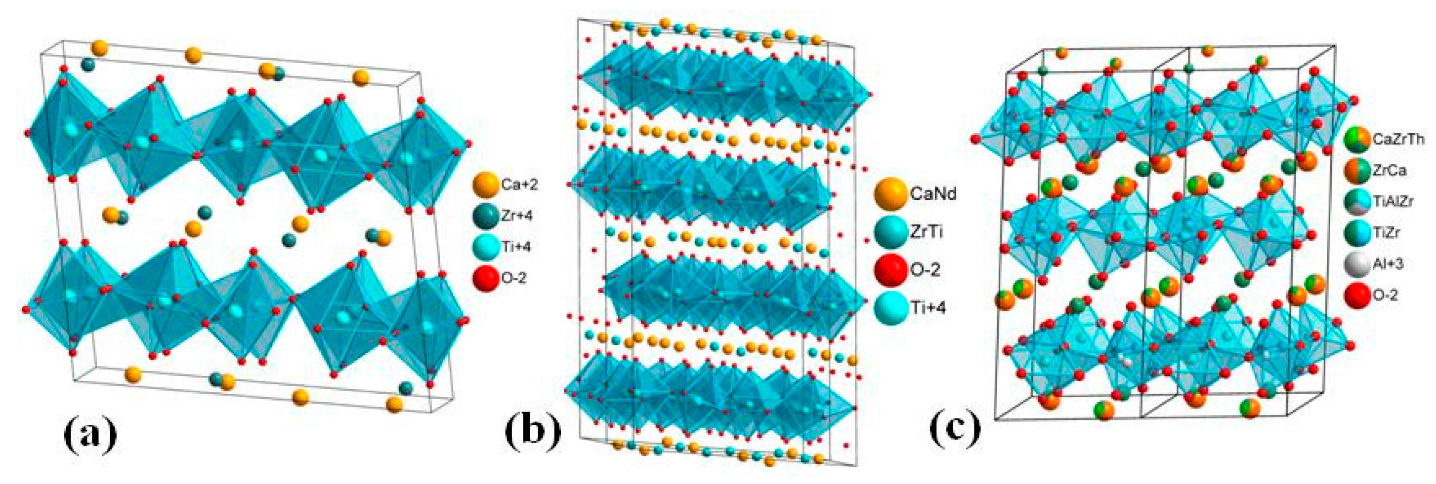
5. Crystal Chemistry of Zirconolite and Its Polytype

As noted, the structure of metamict zirconolite after calcination and for a synthetic analog was first determined in Russia [45,46,79]. Its connection with the fluorite-type lattice was confirmed and it is shown that at temperatures up to 800 °C a cubic disordered metastable phase is formed that does not correspond to the original structure of mineral. At temperatures of 1100–1200 °C, the true structure of monoclinic symmetry is restored with clearly pronounced pseudohexagonality. After the discovery of zirconolite in SYNROC, several notable research programs focusing on the chemistry of zirconolite and related titanate phases began in other countries [31,33,80,81,82,83]. The group of zirconolite varieties consists of five polytypes: 2M, 4M, 3O, 3T, and 6T [82,83,84], where the number dictates the number of layers of TiO6 octahedra that comprise the unit cell, and the letter is the lattice symmetry. Ca atoms are surrounded by O atoms at the vertices of the cube (coordination number, CN = 8), Zr atoms occupy the center of the distorted cube, O atoms occupy seven vertices and there is a vacancy, Ti atoms are in three positions: two in TiO6 octahedra surrounded by six O atoms (M3, M5) and one (M4) in the form of a trigonal TiO5 bipyramid (CN = 5). Ti–O octahedrons form a layer of six-membered rings based on the motif of hexagonal tungsten bronze. Variations in composition of the polytype 2M (aristotype) correspond to the formula CaZrxTi3–xO7, where 0.83 ≤ x ≤ 1.33. Cation substitutions in the Ca, Zr, and Ti positions stabilize the other polytypes (3O, 3T, 4M, 6T) which are characterized by variations in space group symmetry and stacking order of adjacent Ca/Zr and TiOx layers. The volumes of the CaO8 (21.3 Å3) and ZrO7 (15.0 Å3) polyhedra in the 2M aristotype suggest that the former is preferred by large cations of light REE, while small cations of heavier REE enter the Zr positions [31]. Two layers of TiO6 octahedra with interlayer cations Ca2+, REE3+/4+, and An3+/4+ form a single structural block (Figure 1), the rotation of which by an angle multiple of 120° forms a cell of zirconolites 3T or 3O.
The structure of zirconolite-4M is an admixture of 2M polytype and pyrochlore-type modules with cell doubling along the “c” axis and maintaining monoclinic symmetry [85]. The formation of the 4M phase is associated with the isomorphism of tri- (Nd3+) or tetravalent lanthanides and actinides (Pu4+). It was believed [54] that at least 50% and 70% of the [VI,VTi4+] and [VIIZr4+] positions in the zirconolite structure should be filled with cations of just these elements. Later, artificial compounds were obtained in which Ca, Ti, or Zr are absent; their formulas are as follows: REEZrTiAlO7 and REEZrTiFeO7 [86,87,88], CaZrNbFeO7 [89] or Ca1–xNdxHfTi2–xAlxO7 [90]. The regions of stability of zirconolite polytypes in these systems depend on the amount and type of REE and actinides. In samples with the formula Ca1–xLaxZrTi2–xAlxO7, in addition to zirconolite-2M, common secondary phases include zirconium oxide, perovskite, and hibonite (LaTi2Al9O19). In the Nd–Al system, the 2M and 3O polytypes dominate in the x ≤ 0.6 (2M) and 0.8 ≤ x ≤ 0.9 (3O) ranges, and the boundary passes at x = 0.7. Single phase ceramics with the 2M polytype in the Gd–Al, Ho–Al, and Yb–Al systems were found in the range 0.1 ≤ x ≤ 0.8; at higher REE contents, the cubic solid solution (REE,Zr)O2–x additionally appears. In the Nd–Fe and Gd–Fe systems with a bulk composition of Ca1–xLnxZrTi2–xFexO7, there are two polytypes: 2M and 3O. Samples of composition Ca1–xLaxZrTi2–xFexO7 at x from 0.1 to 0.7 contain zirconolite and perovskite; above 0.8, they consist of ZrO2, perovskite and pseudobrookite, and Fe2TiO5 [88].
Attempts to replace Zr4+ in the zirconolite structure with ions with a high charge and close radius (Nb5+) failed [89]. In the Ca(Zr1–xNdx)(Ti2–xNbx)O7 (x = 0–1) series, nearly monophasic samples with the 2M polytype are typical only for 0.05 ≤ x ≤ 0.1, while ceramics with 0.5 ≤ x ≤ 0.9 form with a significant pyrochlore fraction. At x = 0.2, the sample contains polytypes 2M, 3T, and perovskite; in the range from 0.25 to 0.5, the main phases are zirconolite (2M and 4M) and pyrochlore. Minerals with a high content of niobium are known due to the isomorphism of Ti4+ and Nb5+, which is also manifested in pyrochlores and perovskites. Zirconolite-3O with 18 wt% Nb2O5, 19.4 wt% REE2O3, and 6 wt% MnO was found in rocks from the Laacher See (Germany) volcanic complex [36]. In this case, the exchange proceeded according to REE3+ + (Fe,Mn)2+ + Nb5+ = Ca2+ + 2Ti4+. The rocks of the same volcanic complex contain [91] the mineral nogerratite, a structural analog of zirconolite-3O, with the formula (Ce,Ca)2Zr2(Nb,Ti)(Ti,Nb)2Fe2+O14, where one Ti4+ atom per formula unit (apfu) is replaced by Nb5+ with the incorporation of Fe2+. The substitution of Ti for Nb is typical for minerals with a structure close to zirconolite-3O: laachite Ca2Zr2Nb2TiFeO14 and stefanweissite (Ca,REE)2Zr2(Nb,Ti)(Ti,Nb)2Fe2+O14. To describe compositional variations of the minerals, five minerals with a sum of cations equal to 4 and 7 O2- are proposed: CaZrTi2O7, CaZrMe5+Me3+O7, An4+ZrTiMe2+O7, REE3+ZrTiMe3+O7, and REEZrMe5+Me2+O7 [35,52,92]. In the work of [38], taking into account more than 450 analyses, it was shown that the following end-members are more suitable for this (based on the doubled formula with 8 cations and 14 O2−): Ca2Zr2Me5+2TiMe2+O14, REE2Zr2Ti3Me2+O1, CaAn4+Zr2Ti3Me2+O14, CaREEZr2Ti3Me3+O14, and Ca2Zr2Ti2Me5+Me3+O14 (Me2+ + Me3+ = 1) without the Ca2Zr2Ti4O14 end-member. Only the number of Zr atoms remains unchanged (2), which indicates its special role in zirconolite and justifies the name “zirconolite” [43].
The following reactions are most important for the incorporation of actinides and REE into minerals: Ca + Ti = An4+ + Me2+; Ca + Ti = REE3+ + Me3+; Ca + 2Ti = REE3++ Me5+ + Me2+. Two more types of exchanges with complete (Zr4+ = Hf4+) or limited isomorphism [Zr4+ = (Pu, Np)4+] are typical of artificial phases. Hafnium is introduced as a neutron-absorbing additive to reduce the likelihood of a self-sustaining post-closure criticality event. Samples were obtained where Zr in zirconolite was completely replaced by Hf [90,93,94]. Due to the close size of VIIZr4+ (0.78 Å) and VIIHf4+ (0.76 Å), the substitution of Zr for Hf retains the structure of the 2M polytype in CaHfTi2O7 and Ca1−xNdxHfTi2-xAlxO7 (x = 0.01, 0.2). The substitution of Zr4+ for An4+ is an important factor for waste matrices, primarily containing Pu. When Zr4+ is replaced by U4+ [95], the 2M polytype is stable up to x = 0.15; when “x” is from 0.15 to 0.4, the 2M and 4M polytypes of composition CaU0.15Zr0.85Ti2O7 and CaU0.4Zr0.6Ti2O7 coexist, and at “x” from 0.4 to 0.7, along with 4M, pyrochlore appears, which becomes the only phase at higher uranium content (the samples were sintered in an Ar medium at 1400 °C). Similar transformations are observed in zirconolite CaZr1−xPuxTi2O7, “x” = 0–0.6 [96] when Pu4+ enters the Zr4+ positions. At “x” > 0.15, the 2M polytype is replaced by 4M, which at “x” > 0.6 is displaced by the pyrochlore phase. When studying Pu-containing matrices, cerium is usually used as Pu simulant [97] due to the similar ionic radii of Ce3+–Pu3+ and Ce4+–Pu4+ [98]. According to the data of the review [99], the samples containing tetravalent actinides (An = U/Th/Pu) and cerium CaZr1−x(Ce/U/Th/Pu)4+xTi2O7, depending on the value of “x”, are composed of zirconolite polytypes 2M, 4M, and (or) pyrochlore (Table 4).
The CaZr0.8Np0.2Ti2O7 sample consists of 20% 4M and 80% 2M polytypes; during synthesis in an inert atmosphere and in air, Np is in the oxidation state 4+ [100]. The 3T polytype is formed when tetravalent actinides enter the Ca2+ positions and participate in the exchange of cations and charge compensators. It was shown [101] that for the sample of (Ca1−xPux)Zr(Ti2−2xFe2x)O7 composition with increase “x”, the 2M phase transforms into the 3T polytype.
The 3T polytype was stabilized [102] in glass ceramics obtained by cold pressing–sintering, CPS (1250 °C, 4 h, air) or hot pressure sintering, HIP (1250 °C, 100 MPa, 4 h) from a mixture of 30 wt% Na2Al2Si6O16 and 70 wt% zirconolite-forming oxides including PuO2. The purpose of the experiment was to obtain zirconolite (CaZr0.9Pu0.1Ti2O7) in which Pu4+ substitutes directly for Zr. In both cases, Ni powder was added to promote reducing conditions. The formed materials contained 2M with small grains of the 3T polytype around the 2M phase. The appearance of the 3T polytype, albeit in small amounts, contradicts the data of Table 4. Perhaps this is due to the incorporation of Al3+ into zirconolite from glass with the change in the reaction of isomorphic exchange of Zr4+ and Pu4+ with the substitution of Ca2+ for Pu4+ or Pu3+ and, simultaneously, Ti4+ for Al3+ to for charge compensation.
Attempts to increase the loading of the matrix with plutonium and neutron absorbers (Gd, Hf) have been observed to promote a transformation from zirconolite to pyrochlore as the main phase for actinide immobilization [66,67,103,104,105]. The mineralogy of plutonium ceramics was studied depending on impurities, and the limits of occurrence of elements in pyrochlore, zirconolite, brannerite, and the phase fields were determined at 1200–1400 °C on the diagrams: Ca(Zr/Hf)Ti2O7–Ca(Pu/Ce)Ti2O7–CaUTi2O7 and CaO (CaTiO3)–HfO2 (HfTiO4)–(U2/3Pu1/3)O2 ((U2/3Pu1/3)Ti2O6). Depending on the synthesis medium (air, argon), a technology was developed for obtaining pyrochlore matrices with Pu by cold pressing and sintering. Incorporation of the impurities into the zirconolite phase was observed (Table 5), and the amounts of phases in ceramic vary (Table 6) with waste composition.
Despite an increase in the potential Pu wasteloading capacity, the corrosion and radiation resistance of titanate pyrochlore is generally lower than that of zirconolite [24,27,59,67,106]. In particular, the critical dose of amorphization of zirconolite during the decay of 238Pu and 244Cm is 50–70 rel.% higher than that of pyrochlore: 4.6 and 3.0 × 10¹⁸ α–decay/g or 0.5 and 0.3 displacements per atom (dpa), respectively. For minerals, however, the situation is reversed: amorphization dose of pyrochlore is slightly higher than that of zirconolite: 1.1 × 10¹⁹ and 0.9 × 10¹⁹ α-decay/g [26].
In the early 2000s, work in the United States on the immobilization of Pu [67] was discontinued in favor of its use in U-Pu MOX fuel for nuclear reactors under the US–Russia Plutonium Management and Disposition Agreement, signed in 2000, amended in 2010 and entered into the force in July 2011. The countries committed to dispose of 34 tons of surplus (not necessary for defense) weapons-grade Pu in the form of MOX fuel, beginning in 2018. The construction of a plant in Savannah River (USA) started in 2007 but was stopped in 2013 at 70% readiness due to problems with financing, and in 2019 the license for its construction was revoked. The United States has decided [107] to manage plutonium by dilution and isotopic degradation with disposal in GDF located within salt formation (Waste Isolation Pilot Plant, New Mexico). The estimations showed that the disposition of diluted 34 MT of surplus Pu may take up to 31 years and have an associated cost of USD 18.2 billion. Meanwhile, Russia is successfully implementing a program for fabrication of the MOX fuel on an industrial scale and they currently use it in the BN-800 fast reactor at the Beloyarsk Nuclear Power Plant, South Urals.
The study of matrices for the immobilization of plutonium-containing waste continues, for example, in the UK with zirconolite identified as a candidate matrix for Pu [97,99,101,108,109,110,111,112], separate minor actinides, and whole REE–MA fraction [15,17,88,113]. This is due to the facts that (1) the properties of trivalent REE and MA are similar and they will be separated together into a single fraction during the separation of HLW; (2) in SNF and HLW derived from SNF reprocessing, the relative quantity of REE is 15–20 times greater than that of MA; (3) REEs in SNF and HLW are mainly represented by stable isotopes (Table 7), and a small part of their short-lived nuclides will decay during SNF storage; (4) REEs, along with Ca, Zr, and Ti, are the main elements of the zirconolite host phase.
Accounting for very close sizes of Nd3+, Am3+, and Cm3+ [98], zirconolite-containing ceramics and glass ceramics are suitable for MA immobilization [113,114,115,116]. Previously, the similarity of glass ceramics with britholite (REE silicate with an apatite structure) containing La and Nd or Am was shown [117]. Therefore, the synthesis and properties of zirconolite containing Nd3+ are of particular interest. This is also due to the fact that Nd dominates among the REE fission products, where it accounts for about 40% of their total amount (Table 7).
The study on the synthesis of matrices from a mixture of CaF2, Ti, TiO2, ZrO2, Fe2O3, and Nd2O3 by sintering for 6–60 h at 1200–1350 °C stands out [118]. The content of Nd2O3 was set for obtaining zirconolite Ca1−xZr1−xNd2xTi2O7 (x = 0.05–0.30). According to XRD data, in the range of “x” from 0.1 to 0.15 (7.41–10.95 wt% of Nd2O3 in the sample), the 2M polytype transforms into 3T, and there are also coexisting perovskite and pseudobrookite (Fe2TiO5) phases. When replacing Ca2+ with Nd3+, the charge is compensated by the incorporation of Fe3+ instead of Ti4+ according to the reaction Ca2+ + Ti4+ = Nd3+ + Fe3+. These results differ from the data [88] on stability of the 2M polytype, which may be caused by the presence of Ti3+ and Fe2+ due to the presence of titanium metal.
Zirconolite polytypes, depending on composition and substitution reactions involving Nd, are summarized in Table 8.
The incorporation of REE and actinides into zirconolite occurs by a variety of solid solution regimes [116], the main of which is Ca2+ + Ti4+ → M13+ + M23+, where M1 is Ln (lanthanides), An is actinides (Pu, Am, Cm), and M2 is Al or Fe. At M1 = 1, the structure of the (M1)2Ti2O7 phase transforms into pyrochlore (M1 = Gd–Yb, Y) or perovskite (M1 = La–Sm, Pu, Am, Cm). An increase in the REE3+ type and radius from Nd to La in the formula Ca1−xLnxZrTi2−x(Al,Fe)xO7 reduces the 2M field to x = 0.5 [113], the 3O polytype region to “x” = 0.7, and expands the field of perovskite stability. The second most important exchange involving trivalent REE and actinides is Ca2+ + Zr4+ → 2(Ln,An)3+. When zirconolite with composition [Ca1−x/2Ndx/2][Zr1−x/2Ndx/2]Ti2O7 contains neodymium in an amount of 0.5–0.8 atom per formula, the 4M polytype is formed [85].
The incorporations of tetravalent Ce [123] and An into the Zr4+ positions ultimately lead to the formation of pyrochlore CaAn4+Ti2O7, e.g., CaUTi2O7 (betafite). It should be noted, however, that the CaPuZr2O7 end-member does not stabilize the betafite structure; rather, the defect fluorite structure type is preferentially formed. Another exchange option is Ca2+ + 2Ti4+ = An4+ +2(Al,Fe)3+ [124]. For the (Ca1−xPux)Zr(Ti2−2xFe2x)O7 (x = 0.1–0.7), the 2M polytype is stable up to “x” = 0.3, while the 3T appears at “x” = 0.3 and 0.4 [101], and replacing Pu4+ with Ce4+ increases the 2M polytype region [125]. Zirconolite, like its structural relative pyrochlore, has a high capacity for iso- and heterovalent exchanges involving REE, actinides, and small ions with a charge of 2+ to 5+ to compensate for the lattice charge. This distinguishes it from the Nd2TiO5, Nd2Ti2O7, and Nd4Ti9O24 phases, another group of possible matrices for the immobilization of the REE–MA fraction [126].
Below are examples of the formation of zirconolite polytypes. A series of samples [86] of composition REEZrTiAlO7 (REE = La, Ce, Pr, Nd, Sm, Gd, Tb, Y) synthesized by sintering (1450 °C) or melting (1550 °C) was studied. In ceramics with Nd, Sm, and Gd (Figure 2, Table 9 and Table 10), the content of zirconolite is 90–100%, and its composition is close to the target formula. According to X-ray analysis and transmission electron microscopy, TEM (Figure 2), the structure of zirconolite in these samples corresponds to the 3O polytype.
When trivalent (Pu,Am,Cm)3+ and rare-earth elements enter the zirconolite structure, the 2M polytype is replaced by zirconolite-4M and 3O, and sometimes perovskite and pyrochlore appear (at high contents of rare-earth elements and An). The substitution of Zr4+ for Hf4+ does not affect the phase structure. The 3O polytype is stable in the presence of (Fe,Al)3+ cations. In their absence, zirconolite-4M is more stable. The REE–actinide matrices usually contain polytypes 2M and 4M [111], 3O [86], less often 3T [101,125], and there are no data on 6T. The mineral has only three polytypes: 2M with a low content of impurities and a composition close to CaZrTi2O7, 3O, and 3T. The two latter are typical for zirconolites from alkaline rocks with high contents of Fe, Al, REE, U, Th, and Nb [33,37,127].
In murataite–zirconolite ceramics containing Th (Figure 3), the zirconolite polytype 3T is formed [84]. The sample was obtained from a batch of (wt%) 50% TiO2, 10% CaO, MnO, ZrO2, and ThO2, 5% Al2O3, and 5% Fe2O3 by melting in a carbon crucible for 0.5 h at 1500 °C followed by cooling in air. The composition of zirconolite according to SEM/EDS data, in wt%, is 1.8 Al2O3, 10.2 CaO, 39.7 TiO2, 4.0 MnO, 1.4 Fe2O3, 29.5 ZrO2, and 13.3 ThO2, which corresponds to the formula Ca0.67Th0.19Ti1.84Zr0.89Fe0.07Mn0.21Al0.13O7.
A reducing atmosphere (5% H2/N2) is favorable for the formation of the 3T polytype CaZr1−xThxTi2O7; at “x” ≥ 0.20 [111], the Ca0.8Ti1.35Zr1.3Th0.15Al0.4O7 phase crystallizes in the same 3T type [128]. In the SiO2–Al2O3–CaO–ZrO2–TiO2–ThO2 system, an intergrowth of the 2M and 3T polytypes was observed [124], as in the glass ceramics without actinide surrogates produced by sintering albite glass (NaAlSi3O8), CaO, ZrO2, and TiO2 for 0.5–1.5 h at 1100–1300 °C [129] and having 3T as intermediate phase.
Data on the polytypes of zirconolite in glass ceramics are ambiguous. On the one hand, as the content of CeO2 and Nd2O3 was increased to 15 wt%, the transformation of the 2M polytype into 4M was observed [130]. When studying [116] glass ceramics with phases of the composition Ca1−xZr1−xNd2xTi2O7, Ca1−xNdxZrTi2−xAlxO7, and CaZr1−xCexTi2O7 (x up to 0.5), the transition of the 2M polytype to 4M was not observed, in contrast to ceramics with the same degree of substitution. The dominance of 2M in glass ceramics can be explained by a low content of rare-earth elements and actinides (10–15 wt%) in the phase due to limited solubility in glass [131,132] and rather low distribution coefficients (Kd) between zirconolite and glass [19,114,115,124,133,134,135]. The Kd values for Nd3+ are only 1.5–3, decreasing with an increase in the crystallization temperature of zirconolite in glass and the total neodymium content [116,136].
Synthesis conditions (temperature, pressure, duration, and ambient atmosphere) affect the structure of zirconolite-based matrices in the following ways: (1) preservation of charge relics and intermediate phases; (2) variations in the valency of elements under different oxidizing conditions; (3) change in composition upon reaction with a container during sintering or a crucible during melting, contamination of the charge with impurities, or due to the addition of titanium to create reducing conditions during hot pressing or initiation of melting in a cold crucible. This will lead to a change in the chemical and phase composition of the matrix compared to the target (calculated) value, which may affect its ability to retain actinides. Let us consider these phenomena in more detail and their possible role in changing the phase composition and properties of the samples.

6. Influence of Synthesis Conditions on the Structure of Zirconolite-Bearing Matrices

In order to obtain ceramic wasteforms containing a realistic HLW (or surrogate) fraction, sintering at normal or elevated pressure, melting in electric furnaces, or induction heating is necessary [15,134,137,138,139,140]. Sintering a mixture of clay and radioactive waste at 1000 °C was carried out as early as the 1950s [141]. Synthesis of actinide matrices by cold pressing–sintering (CPS) was tested on a larger number of samples with surrogates and actinides (Pu, Np, Am, and Cm).
Synthesis of zirconolite by the CPS method is considered in many publications [142,143,144,145,146]. No zirconolite is formed within 15 h in experiments at 800 and 900 °C, with peaks corresponding to titanium and zirconium oxides, as well as calcium titanate (perovskite) detected in on X-ray diffraction patterns. These oxides are components of the mixture and perovskite is an intermediate product. Zirconolite is detected after 15 h of sintering at 1000 °C or 10 h at 1100 °C (Table 11).
With an increase in the temperature and duration of the experiment, the overall yield of zirconolite increases, and the accompanying proportions of titanium and zirconium oxides decrease. Zirconolite is the main phase at 1200 °C (20 h), but the content of rutile, baddeleyite, and perovskite remains high. An increase in temperature to 1300 °C (20 h) leads to a decrease in their amounts, and a further increase in temperature or time does not affect the phase composition of the samples. At 1550 °C, the mixture melted, since the melting point of stoichiometric zirconolite is 1525 °C. The composition of zirconolite was identified to be Ca1.09Zr1.07Ti1.89O7 (1500 °C, 5 h) and Ca1.12Zr1.04Ti1.90O7 (1500 °C, 20 h). A small amount of perovskite (up to 5%): Ca1.06Ti0.93Zr0.03O3 (run 14) and Ca1.08Ti0.94Zr0.04O3 (run 121) was observed even at the maximum temperature and sintering time (Figure 4).
Ceramics of composition CaZrTi2O7 were obtained by sintering for 10 h at 900–1450 °C and studied by X-ray diffraction, SEM, and TEM [146]. The amount of CaTiO3 (perovskite) and ZrO2 (baddeleyite) after 1200 °C decreased to 2 wt%; after 1300 °C (Table 12), zirconolite became the main phase (>99%).
The CPS method has been proposed for industrial immobilization of plutonium into titanates with the structure of pyrochlore and zirconolite [66,103,104,105,138,147,148]. This process generally includes grinding oxides to a size of less than 20 μm by ball milling, homogenizing, granulating and pressing the mixture at 10–20 MPa, and then heating in air or in an Ar medium at 1300–1400 °C for 4–6 h. The final product has a density of 5.5 g/cm3 and consists of pyrochlore (90%), brannerite and rutile (5% each), and zirconolite and oxide (U,Pu)O2 (up to 1%) with grains of micron size. To test its possible scale up to industrial application, around one thousand samples were made, weighing 500 g with dimensions of 6 cm in diameter and 3 cm in height (similar to a hockey puck). Ce, U, and Th oxides were used as Pu surrogates, but samples with 10–12 wt% PuO2 were also produced. In all samples, the 2M zirconolite polytype (sp. group C2/c) is formed, which was confirmed by high-resolution TEM data.
Pressing at 1 atm and sintering are used to manufacture nuclear fuel based on U [149] and with additions of Th, Pu, and minor actinides (Np, Am, and Cm) [150,151]. The process takes place above 1500 °C in a reducing/inert environment. To obtain UO2–AmO2 fuel, a mixture of crushed U3O8 and AmO2 is pressed into pellets at 450 MPa and fired for 4 h at 1750 °C in a medium of 96%Ar/4%H2. MOX fuel (U–Pu) is sintered for 24 h at 1700 °C in a reducing atmosphere. The CPS method for obtaining actinide matrices is simpler than the production of nuclear fuel, since it does not require such high temperatures and a special gas atmosphere. The conditions for obtaining zirconolite: 20 h at 1300 °C, 10 h at 1400 °C, and 5 h at 1450 °C are determined for the CaZrTi2O7 composition, and the same parameters are necessary for the synthesis of zirconolite with actinides (Th, U, and Pu) and their associated REE surrogates [152,153,154]. Synthesis can be accelerated by attrition of the initial mixture in an induction rotator or an impact-type planetary mill [155]. In this case, a dense (open porosity 1%, density 4 g/cm3) single-phase ceramic, consisting of zirconolite with the composition CaZr0.75U0.25Ti2O7, could be obtained in just 2 h at 1350 °C.
To accelerate the preparation of zirconolite ceramics at a lower temperature, it has been proposed to perform the sintering stage with the addition of a flux (CaF2) and an oxidizing agent (Fe2O3) and to replace part of the TiO2 in the charge with more reactive Ti [156]. Samples were prepared from a mixture of CaF2, Fe2O3, Ti, TiO2, and ZrO2. The CeO2 simulant was added based on substitution in the zirconolite formula Ce4+ = Zr4+ in the range from 0 to 50 at.% with a step of 10 at.%. The powders were pressed into pellets with a diameter of 12 mm and sintered for 6 h at a temperature of 900 to 1300 °C. Corrosion-resistant ceramics containing zirconolite, perovskite, and pseudobrookite (Fe2TiO5) were obtained at 1200 °C according to the reaction 2Fe2O3 + 3Ti + TiO2 + 2(1 − y)ZrO2 + 2CaO + yCeO2 = 2CaZr1−yCeyTi2O7 (zirconolite) + 4Fe, and CeO2 appears at y = 0.5.
Another option is pressure-assisted sintering, either using isostatic (HIP) or axial (HUP) hot pressing [148] or electric pulse sintering (SPS) methods. As a result, the target phases are obtained in a short time and at lower temperatures. Synthesis is also accelerated by replacing the oxide mixture with a sol–gel precursor, which is prepared by mixing solutions with matrix and waste components, followed by neutralization. As a result, colloids and a gel are formed, which are dried, pressed, and sintered. Hot pressing of a mixture of composition Ca0.75Ce0.25ZrTi1.625Fe0.375O7 for 2 h at 1320 °C and 100 MPa was used to obtain [157] a matrix of zirconolite (Ca,Ce)Zr(Ti,Fe)2O7 and perovskite, varying in composition from CaTiO3 in the center of the grains to (Ca,Ce)(Ti,Fe)O3 at the edges. Under similar conditions (HIP, 1320 °C, 100 MPa, 2 h), zirconolite Ca0.75Ce0.25ZrTi2O7 was synthesized [71] from a sol–gel charge with the addition of 2.2 wt% Ti to stabilize Ti3+ in order to ensure the electroneutrality of the structure during the exchange reaction: 0.25 Ca2+ + 0.25 Ti4+ = 0.25 Ce3+ + 0.25 Ti3+.
Two types of matrices based on zirconolite for the immobilization of Pu-containing wastes were synthesized by hot isostatic pressing (HIP) using steel (SS) or nickel (Ni) canisters [158]. The HIP-SS sample contained 13.5 wt% PuO2, 10 wt% HfO2, 4.2 wt% Gd2O3, 4.2 wt% Sm2O3, and targeted a phase assemblage comprising 80% zirconolite (CaZrTi2O7), 10% hollandite (BaAl2Ti6O16), and rutile (TiO2) each. The composition of zirconolite was determined to be Ca0.47Pu0.34Gd0.15Sm0.13Hf0.25Zr0.55Ti1.74Al0.37O7 from EDS analysis. The HIP-Ni sample with 15 wt% PuO2 and 6 wt% Gd2O3 was designed to produce pyrochlore, 25% zirconolite, and rutile impurities. The composition of zirconolite determined by SEM/EDS corresponded to Ca0.72Gd0.13Pu0.22U0.09Th0.02Zr0.87Ti1.76Al0.12Ni0.06O7.
SYNROC-Z with waste from the GANEX (Group Actinide Extraction) process was obtained by hot pressing, reported to comprise hollandite, perovskite, rutile, zirconolite. Equilibrium during synthesis is achieved in 3–5 h at 1150–1200 °C, and pressure variations in the range from 10 to 40 MPa have almost no effect on the rate of phase formation [159].

7. Samples Obtained by Melt Crystallization

Another way to obtain HLW matrices is melt crystallization. The high melting point of zirconolite (1525 °C) complicates its synthesis in electric furnaces. A method of melting in a “cold” crucible induction melter (CCIM) with temperatures from 1200 to 3000 °C has been proposed [63,134,137,160]. Zirconolite-rich ceramic matrices have been prepared [137] by CCIM at 1600–1700 °C; consisting of zirconolite (70%), perovskite (10–30%), and an admixture of Zr and Ti oxides (rutile). The optimal content of actinide waste (Pu, minor actinides, or REE–MA fraction) in it is estimated at 10 wt%, and the mass of the resulting blocks can vary from 2 to 30 kg. From a mixture of oxides of Ca, Zr, Ti, Gd, and Al, taken in a ratio corresponding to the formula of zirconolite, four samples were prepared by CCIM [160]. The temperature varied from 1550 to 1650 °C depending on the charge composition decreasing with an increase in the Gd content in the mixture. The difference in compositions by SEM and chemical analysis (Table 13) is due to their heterogeneity. In addition to zirconolite, zirconium and gadolinium oxide, rutile, perovskite, aluminum titanate (pseudobrookite), and glass with high silica content were found (Figure 5, Table 14 and Table 15).
Samples I and II contain two forms of zirconolite. From early (1) to late (2) zirconolite, the Zr content decreases and the Ti content increases, while the Gd content remains at the same level (Table 16). The late zirconolite-2 is characterized by a low Zr content and is enriched in Gd and Al. The amount of (Zr,Gd)O2−x increases in the sample with the maximum ZrO2 content in the charge. Silica, small amounts of alkalis, and iron enter the melt when the refractory coating of the crucible dissolves.
Two samples containing an REE–actinide surrogate fraction were fabricated by CCIM using a batch mixture of composition 15.5 wt% CaO, 44.5 wt% TiO2, 20.5 wt% ZrO2, 5.0 wt% CeO2, 2.0 wt% Eu2O3, 4.0 wt% La2O3, and 8.5 wt% Nd2O3 (target formula Ca1.01Ti2.04Zr0.61La0.09Ce0.11Eu0.04Nd0.19O7). To initiate melting, a Zr ring was placed onto the surface of the batch. After the end of the experiment the melt was solidified in the crucible. To assess the effect of heat treatment, the sample obtained was additionally calcined for 4 h at 800 °C. According to XRD and SEM/EDS data (Figure 6), both samples are dominated by zirconolite, with minor ZrTiO4 (srilankite) and TiO2 (rutile). SEM images revealed two types of zirconolites of different composition (Table 17). We did not determine their polytypes, but it is likely that zirconolite-1 is a 2M polytype, while zirconolite-2 is a 4M polytype (or alternatively zirconolite-4M and pyrochlore). The effect of heating on the structure of the sample was not revealed.
Because Nd3+ serves as a highly suitable crystal–chemical analogue for actinides (Am, Cm) and REE–actinide fraction, data on two samples with Nd2O3 obtained by CCIM at a scale of approximately 1 kg (Figure 7, Table 18) are of great interest. Sample No. 4 was synthesized from a charge of the zirconolite composition Ca0.5Nd0.5ZrTi1.5Al0.5O7, while the target phase in the synthesis of sample No. 5 was Nd2Ti2O7 titanate with a perovskite structure. According to XRD and SEM/EDS data [161,162], sample No. 4 consists of two types of zirconolites, an admixture of Zr oxide, perovskite, rutile, and hibonite. The compositions of both generations of zirconolite were calculated using the formula with 7 O2− and the sum of cations equal to 4. A small amount of iron in this sample is most likely associated with impurities in initial reagents for synthesis. Early formation of Zr oxide (Sample No. 4) is caused by a wide field of its crystallization in this system. As in the previous samples with Gd, the late generation of zirconolite grains contains less Zr, more Ti, and the amount of Nd in it increases. A similar sequence of the crystallization of phases beginning from Zr–Gd oxide and zirconolite to perovskite and rutile was formerly observed at cooling of a melt with Ca0.9Gd0.1ZrTi1.9Al0.1O7 composition [163].
Sample No. 5 was composed of 80% Nd2Ti2O7 phase and 20% zirconolite-3O (Table 18). The phase composition of the sample differs from the target value by the presence of zirconolite due to the contamination of the charge with alumina (impurity in precursor). It was interesting to note that the zirconolite formula (Table 18) has a higher number of O atoms (7.33) relative to the theoretical value (7.0). One explanation could be the partial reduction of Ti4+ to Ti3+ due to the use of a ring of metallic Ti to promote melting with exchange reaction in the zirconolite: Ca2+ + Ti4+ = Nd3+ + (Al,Ti)3+.

8. Other Methods for Obtaining Zirconolite-Containing Matrices

In recent years, spark plasma sintering (SPS) has become a popular method for the synthesis of matrices with waste simulants, including zirconolite [16]. In this case, the material is subjected to uniaxial pressure and heating by electric current pulses. SPS is believed to be advantageous to produce dense ceramics as it allows rapid synthesis at a lower temperature, compared to the processing times of CPS or HIP (typically several hours). Zirconolite ceramics with a grain size of about 2 microns with near-theoretical density have been obtained in 1 h at 1200 °C from a mixture of CaTiO3, ZrO2, TiO2 using SPS [164]. Spark plasma sintering was applied to produce zirconolite with composition Ca0.8Ce0.2ZrTi1.6(Me3+)0.4O7, Me = Fe and Al [165]. CaTiO3, ZrO2, CeO2, TiO2, Al2O3, or Fe2O3 powders were calcined for 12 h at 800 °C, mixed in ratios corresponding to target formulas, ground, and homogenized in planetary ball mill. Then 5 g of the mixture were placed in a cylindrical graphite mold with a diameter of 20 mm with graphite foil spacers for uniform current flow and pressed at a load of 3 tons for 5 minutes to form a tablet. The mold was loaded into the SPS system and heated at a rate of 100 °C/min to 1320 °C at a uniaxial pressure of 15 MPa in vacuum. The content of zirconolite-2M in the sample is >80%; there is also a significant amount of cerium-containing perovskite due to the reduction of Ce4+ to Ce3+ (quantified by Ce L3-edge XANES analysis). The use of Al3+ as a charge compensator in the reaction Ca2+ + Ti4+ = Nd3+ + Al3+/Fe3+ reduced the proportion of perovskite in ceramics.
To obtain zirconolite-rich matrices, heating with high-frequency currents and self- propagating high-temperature synthesis (SHS) has also been investigated. Syntheses have been reported using inactive REE simulants (Ce and Nd) [166,167,168,169,170]. Besides zirconolite-2M, the samples contain perovskite and, less often, pyrochlore at the elevated surrogate concentration, with REE elements preferentially located within the perovskite phases. An example of the synthesis of zirconolite ceramics from a mixture of MoO3, CaO, Ti, ZrO2, Al2O3, and Nd2O3 is described in [170]. The target phases were Nd–Al zirconolite and metallic Mo in accordance with the intended reaction: 4MoO3 + 3(1 − x)CaO + 6Ti + 3ZrO2 + 1.5xNd2O3 + 1.5xAl2O3 = 3Ca1−xNdxZrTi2−xAlxO7+2x + 4Mo. The amount of Nd2O3 in the batch was calculated to replace up to 30 at% Ca in the zirconolite formula. The mixture (20 g) was triturated and homogenized in an agate mortar, pressed at 10 MPa into tablets, and the SHS process was initiated with a spiral of W heated by a current of 50–60 A. After 20–25 s after the start of the reaction, the products were compacted at a pressure of 40–50 MPa using a hydraulic press for 60 s. The main phases are Nd–Al zirconolite, metallic Mo, and an admixture of rutile and perovskite. The composition of zirconolite corresponds to the formula Ca0.76Nd0.17Zr1.13Ti1.75Al0.15O7, which was somewhat different from the target with “y” = 0.15: Ca0.85Nd0.15ZrTi1.85Al0.15O7. Ceramics were also synthesized [168,169] with other actinide simulants (Ce) and a reducing agent Cu,Ca(NO3)2. When using a mixture of CuO, CaO, Ti, TiO2, ZrO2, and CeO2 the goal was to fabricate Ce-containing zirconolite according to the reaction: 6CuO + 2CaO + 3Ti + TiO2 + 2ZrO2 + CeO2 = 2Ca(Zr,Ce)Ti2O7 + 6Cu. Due to the reduction of cerium to Ce3+, perovskite was formed, the content of which increases from 12 to 67% with an increase in the share of CeO2 in the charge with a decrease in the proportion of zirconolite [169]. Despite the simplicity of SHS, its main disadvantages are less controlled synthesis parameters, high gas release and entrainment of solid particles–aerosols, which is unacceptable for highly active materials, ceramic porosity, small size and weight of blocks (hundreds of grams), lack of experiments with transuranium actinides, and verification of the technology in a remote environment. Solutions were proposed for a number of problems, for example, in order to increase the density, it was proposed to press the sample after completion of SHS; however, this leads to a complication of the technology when it is carried out remotely.

9. Influence of Oxidative Conditions of Synthesis on the Structure of Matrices

Actinide and REE cations can have different oxidation states and sizes depending on the imposed conditions during materials synthesis. At high temperatures, the following ions are stable: U4+/5+, Np4+, Pu3+/4+, Am3+, Cm3+, and Ce3+/4+, the remaining REEs are in the trivalent state. Variations of PO2 from 0.2 atm (air) to 10−4 atm (N2 medium) do not affect the phase composition of zirconolite ceramics with REEs (Ce, Nd) and actinides (U, Np, Pu) obtained by sintering or hot pressing at 1250–1400 °C [171]. When the charge and size of element cations change, they will enter different structural positions of zirconolite, replacing Ca2+ and/or Zr4+ cations. The products of zirconolite synthesis with Ce and Pu by sintering for 10–80 h at 1200–1550 °C in various media (air, N2, Ar, a mixture of 3.5% H2 + 96.5% N2) or hot pressing (2 h at 1150 °C and 200 atm) were studied [172,173]. Ce is present in the samples as Ce3+ or/and Ce4+, which models the behavior of Pu ions due to close sizes, for example, for coordination numbers (CN) equal to VI they are 0.101 (Ce3+)–0.100 (Pu3+) nm and 0.087 (Ce4+)–0.086 (Pu4+) nm [98,124]. In experiments with Pu, instead of zirconolite CaZrTi2O7, its hafnium analogue CaHfTi2O7 has been used to avoid overlapping of the LIII (Pu) and K (Zr) lines when determining the plutonium valence in zirconolite by X-ray absorption spectroscopy (XAS) in the near-edge region of the X-ray absorption (XANES) spectrum. The change from an oxidizing (air) or neutral (Ar, N2) medium to a reducing one (3.5% H2/N2) leads to the appearance of 10% perovskite in samples with Pu and Ce due to the formation of their respective trivalent cations. In samples with Np, perovskite is not formed, since it only exists in the Np4+ state over the entire PO2 range.
A series of CaZr1−xCexTi2O7 samples (x from 0 to 0.4) was fabricated by the CPS method at oxidizing, inert, and reducing conditions [110]. They contain two polytypes of zirconolite (2M and 4M) and perovskite, the relative yields of which were dependent on the synthesis conditions and the value of the Ce3+/Ce4+ ratio. Under oxidizing conditions, where Ce4+ is stable, perovskite is absent. In inert and reducing media, a part of Ce4+ is reduced to Ce3+, and although zirconolite-2M remained the dominant phase, up to 8% of Ce-bearing perovskite also appeared. During the synthesis of ceramics with CeO2 (simulator of tetravalent actinides) by sintering at 1250–1400 °C in air in the range of 15–25 wt% CeO2, the transition of the 2M polytype to zirconolite-3T is observed [125].
Another possible reason for the replacement of zirconolite with perovskite and zirconium oxide is associated with the reduction of Ti4+ to Ti3+ [174]. Zirconolite CaZrTi2O7 was prepared from a sol–gel mixture, and the mixture was dried and calcined for 1 hour in air at 700 °C, granulated, and sintered for 60 h at 1400 °C in air. To determine the effect of the medium on the stability of zirconolite, the sample was crushed to 100 μm and heated again in a flow of 3.5% H2/N2 at 1400 °C, first for 20 h and then for another 40 h. As a result, its structural rearrangement occurred with the formation of an oxide phase with the structure of fluorite and perovskite (CaTiO3). The shift of the position of the Ti–K edge (XANES method) to lower energies indicates an increase in the relative quantity of Ti3+ in the sample. The maximum shift (60 h, 1400 °C, 3.5% H2/N2) is a quarter between the values for Ti2O3 and TiO2, i.e., 25% of the titanium in the sample is suggested in the Ti3+ state.
The difference in the phase composition from the target value may be due to a change in the composition of the samples due to interaction with the container during the preparation of matrices by hot pressing or the reaction of the melt with the walls of the crucible. This effect was found when preparing ceramics by hot pressing [108,175]. The reaction of stainless steel and ceramic during the HIP process resulted in the formation of a transition region due to Fe diffusion with a change in the amount of zirconolite at the interface. These interactions do not create lower durable phases and are unlikely to have a detrimental effect on the stability and chemical resistance of SYNROC. In glass ceramics composed of 70 wt% CaZr0.8Ce0.2Ti2O7–30 wt% NaAlSi3O8 glass obtained by HIP, along with the zirconolite-2M, there are perovskite, sphene CaTiSiO5, baddeleyite m-ZrO2, zircon ZrSiO4, rutile TiO2, and CeO2. The predominant oxidation state of cerium is Ce3+, probably due to the influence of the steel canister [176].
When studying actinide matrices, stable simulants (REEs, Hf) or weakly active actinides (U, Th) are used. Tetravalent cations (Hf, Ce, Th, U) serve to replace Pu4+ and Np4+, while to imitate trivalent cations (Pu, Am, Cm) close to them in size, Ce3+ and Nd3+ are used [137]. Samples of the composition Ca1−xCexZrTi2−2xAl2xO7 (x = 0–0.35) were studied [97]. In the compositional range 0.05 < x < 0.2, the proportion of zirconolite is more than 94%. Zirconolite Ca0.8Ce0.2ZrTi1.6Al0.4O7 contains 9.3 wt% CeO2, which, taking into account the difference in atomic masses of Ce and Pu, corresponds to 14.9 wt% PuO2. For zirconolite, a large number of studies have been carried out with transuranium actinides Pu and Np, and there are some data on the behavior of Cm; the following section will examine these systems in detail.

10. Zirconolite Matrices with Transuranium Actinides

Between 1994 and 1997, collaborative work at ANSTO (Australia) and LLNL (USA) focused on ceramics with a high targeted yield of zirconolite, containing ~12 wt% Pu and 17 wt% Gd and Hf (neutron absorbers) for criticality control. Samples were prepared for sintering by uniaxial or hot isostatic pressing. The HIP method was used to fabricate the samples with REE surrogates of up to 10 kg and with a Pu weight of 0.4 kg (50 g of PuO2). To prevent an inadvertent chain reaction, the addition of U is required which limits the Pu content in zirconolite. As a result, ceramics composed of 95 wt% pyrochlore (Ca0.89Gd0.22Hf0.23Pu0.22U0.44Ti2O7) and 5 wt% rutile (Ti0.9Hf0.1O2) were obtained [138,148]. Samples containing Pu and U, Th and U, or Ce and U consisted of pyrochlore, an admixture of brannerite and rutile. In ceramics sintered in air, the proportion of brannerite increases relative to pyrochlore compared to synthesis in Ar. During sintering in 3.7% H2/Ar, brannerite and rutile disappear, but zirconolite-2M and perovskite appear in addition to the main pyrochlore phase. A change in temperature from 1250 °C to 1400 °C had little effect on the composition of phases and the structure of ceramics, except for the partial retention of Pu oxide at lower temperatures, and an increase in the grain size and density of ceramics with an increase in temperature to 1350 °C. From the point of view of crystal chemistry, Th4+ is the best analogue of Pu4+ in the experiments with surrogates.
Pyrochlore ceramics for immobilizing excess Pu in the United States evolved from early forms of SYNROC to meet the requirements of the fissile materials disposal program [67,177]. The basic composition (12 wt% PuO2, 24 wt% UO2) consists of 80% pyrochlore, 12% brannerite, and 8% rutile. Due to impurities, zirconolite appears in Pu in the form of several polytypes: 2M, 3T, and 4M with various stacking of Ca/Zr and TiOx layers [66,104]. After the curtailment of the Pu utilization program, interest in pyrochlore faded, but the study of zirconolite as a matrix of small actinides and REE–MA fraction became more active. Therefore, all the results of the study of zirconolite are of interest.
The studies of zirconolite with Np and Pu started in the 1980s [178,179] and continued into the 1990s [171,172]. The samples were sintered for 20 h at 1150 °C–1400 °C in air, in an inert (Ar, N2) or reducing medium (3.5% H2/N2, graphite crucible) at 1 atm or increased (20 MPa) pressure. The valency of Ce and Pu in the samples depends on the conditions of synthesis–fraction of the oxidized state decreases from 100% to 0 when air is replaced by an inert and reducing medium, regardless of the presence of Al3+ as a charge compensator. Even under the most reducing conditions (3.5% H2/N2), Np4+ is stable, which distinguishes it from Ce and Pu with more common trivalent state. The Pu and Np cations are distributed between the Ca and Zr sites of the zirconolite. The amount of Pu in the Zr4+ position increases with an increase in the fraction of the Pu4+ state and a decrease in the content of Al3+. Although the radius of Np4+ is larger than that of Zr4+ and Pu4+, it mainly enters the Zr4+ positions. In addition to zirconolite, the samples always contain perovskite, in which the degree of oxidation of actinides depends on the composition; the content of Al3+: Ce and Pu in perovskite are in the 3+ state (if there is little Al3+) or 4+ (in the case of a lot of Al3+) both during synthesis in air and under reducing conditions and inert environment. In the absence of Al3+, the perovskite composition is determined by the reactions Ca2+ + Ti4+ = (Ce,Pu)3+/4+ + Ti3+ and 2Ca2+ = (Ce,Pu)4+ + vacancy.
When Zr4+ is replaced by Pu4+ in CaZr1−xPuxTi2O7 zirconolite (x = 0.1–0.6), zirconolite-2M is replaced by 4M polytype and then by pyrochlore [96]. Zirconolite-2M is stable up to 15 at% Pu4+, 4M forms near CaZr0.6Pu0.4Ti2O7 composition, and pyrochlore is stable at a higher Pu content. The stability of zirconolite polytypes is sensitive to the size of ions in the VIZr4+ position. The reduction of Pu4+ to Pu3+ leads to the replacement of zirconolite-4M by perovskite and, possibly, zirconolite-3T. Zirconolite with Pu is superior to titanate pyrochlore in terms of radiation resistance and stability in water [67].
Two samples with 10 wt% PuO2 based on zirconolite or monazite were synthesized [179]. The batch was pressed (800 MPa) and sintered for 10–15 h at 1450 °C. The formulae of zirconolite (Ca0.87Pu0.13)Zr(Al0.26Ti1.74)O7 and monazite (Ca0.09Pu0.09La0.73Th0.09)PO4 were determined. The density of ceramics is 4.4–5.1 g/cm3, or 92–96% of the theoretical value. The XANES showed that plutonium is present as Pu4+ (zirconolite) and Pu3+ (monazite).
Ceramics with composition, wt%: CaO (13.4–15.8), Al2O3 (0–1.7), Gd2O3 (0–5.9), TiO2 (40.8–45.2), ZrO2 (29.4–31.3), and PuO2 (7.7–8.8) with zirconolite were obtained by melting a mixture of oxides at 1550 °C for 1 h [180]. The proportion of zirconolite in the samples is 80–85%. When the batch is melted under reducing conditions, perovskite also appears.
The possibility of incorporating Pu with isotopic composition 91% 239Pu, 9% 240Pu into zirconolite (Ca1−xPux)Zr(Ti2−2xFe2x)O7 (x = 0.1–0.7) was studied [101]. Up to x = 0.3, the 2M polytype is stable, the 3T polytype is stable up to x = 0.4 (20 wt% Pu), and with an increase in x to 0.6 and 0.7, in addition to the 3T polytype, oxides of Fe and Pu also appear.
The work of [108] presents data on zirconolite ceramics with U/Th and Pu obtained by hot isostatic pressing. Mixtures of oxides weighing from 200 (U/Th sample) to 20 g (with Pu) were sintered for 3 h at 1280 °C, 100 MPa in argon. In addition to zirconolite, both samples contain hollandite, and the U/Th matrix also contains brannerite. The leaching rate for Pu and Hf < 10−5 g/m2/d, and for Gd between 10−4 and 10−5 g/m2/d.
The work of [181] studied the leaching of Ce– and Pu–zirconolite in 1 M HCl, 2 M NaCl, 1 M NaOH, H2O) at 100–300 °C. Most of the runs were carried out with zirconolite containing 238Pu and 239Pu in 1 M HCl. Zirconolite with 238Pu is X-ray amorphous; with 239Pu, it is crystalline. Some conclusions were made: (1) after 14 days of interactions, its change is insignificant in all solutions, except for 1 M HCl; (2) dissolution of zirconolite in 1 M HCl solution is incongruent; (3) the degree of change slightly increases with increasing temperature; (4) at 200 °C in 1 M HCl amorphous zirconolite with 238Pu changed to a much greater extent than crystalline samples containing 239Pu.

11. Radiation Damage in Zirconolite Matrices

Damage from α-decay was studied in zirconolite containing up to 4 mol.% 238PuO2 [178,179,182,183,184,185,186]. During irradiation, the density decreases by 6%, and amorphization occurs at a dose of 2.13 × 1025 α-decays/m3. A study of zirconolites containing 10 wt% 239PuO2 or 238PuO2 and obtained by sintering was performed [187]. The sample with 239PuO2 was composed of zirconolite Ca0.92Pu0.13Zr1.01Ti1.72Al0.25O7. The XANES study showed that Pu was in the Pu4+ state. Radiation damage was studied in a sample with 10 wt% 238PuO2, since the activity (number of decays per second) for 238Pu is 6.3 × 10¹¹ Bq/g compared to 2.2 × 10⁹ Bq/g for 239Pu. Some of the samples were kept at 250 or 500 °C. At 25 °C, amorphization of zirconolite with 238Pu started at 2.2 × 10¹⁸ α-decay/g and ended after 3 years at 5 × 10¹⁸ α-decay/g (0.45 displacements per atom). An increase in temperature slows down rate of amorphization and the associated decrease in sample density.
A large number of studies have been carried out on the irradiation of zirconolite with accelerated ions of different energies. In [89] zirconolites of composition CaZrTi2O7, Ca0.8Ce0.2ZrTi1.8Al0.2O7, Ca0.85Ce0.5Zr0.65Ti2O7, Ca0.5Nd0.5ZrTi1.5Al0.5O7, CaZrNb0.85Fe0.85Ti0.3O7, and CaZrNbFeO7 were irradiated with 1 MeV Kr+ in the range from 25 to 973 K and examined in situ in a transmission electron microscope. Radiation-induced amorphization was studied by electron diffraction and high-resolution electron microscopy. As irradiation proceeds, the structure of zirconolite transforms into a fluorite sublattice due to the disordering of cations. At room temperature, zirconolites were amorphized at dose of 2 × 10¹⁵–3.9 × 10¹⁵ ions/cm2. The dose increases with temperature at different rates for each phase. The critical temperatures were 550 K for CaZrNbFeO7, 590 K (CaZrNb0.85Fe0.85Ti0.3O7), 640 K (CaZrTi2O7), 900 K (Ca0.8Ce0.2ZrTi1.8Al0.2O7), 1000 K (Ca0.85Ce0.5Zr0.65Ti2O7), and 1020 K for Ca0.5Nd0.5ZrTi1.5Al0.5O7. Reduction of Ca content appeared to increases the tendency of the material to undergo amorphization.
Polycrystalline samples composed of zirconolite (Ca0.8Nd0.2)Zr(Ti1.8Al0.2)O7 and perovskite (Ca0.9Nd0.1)(Ti0.9Al0.1)O3 were irradiated with Kr+ ions with an energy of 2 MeV to a dose of 5 × 10¹⁵ ions/cm2 to simulate the recoil of plutonium nuclei during alpha decay [188]. Nd3+ was chosen to replace Pu3+ due to similar ionic radii at the same oxidation states. During irradiation, an amorphous region appeared in the zirconolite, separated from the initial crystalline material by a thin zone (40–60 nm), where the zirconolite-type lattice disappears, but the fluorite-type sublattice is still preserved.
Fewer investigations concern the irradiation of glass ceramics with zirconolite, although their properties may change under the action of the decay of fission products and actinides. The work of [189] revealed a change in the shape and composition of the grains of the phases of glass ceramics irradiated with Si ions with an energy of 15 MeV. When zirconolite glass ceramics were irradiated with 21 MeV Au+ to a dose of 1015 ions/cm2 [190], a change in the volume of the glass phase, amorphization, and a change in the shape of zirconolite grains were revealed; in addition, the Ce content in the glass increased.
A sample with Nd–zirconolite obtained by sintering was irradiated with 120 MeV Au+ ions [191] until amorphization, which was established by the disappearance of reflections in the X-ray diffraction pattern. Zirconolite of the composition Ca0.8Nd0.2ZrTi1.8Al0.2O7 was irradiated with 30 keV He+ ions [192]; although X-ray diffraction patterns showed a decrease in intensity and an increase in the width of the peaks, complete amorphization did not occur at a dose of 1017 ions/cm2, which confirms its high resistance to radiation. Irradiation with 12 MeV Au+ up to 100 displacements per atom [193] caused amorphization of zirconolite in glass ceramics, which has a lower elastic modulus, compression limit, and higher impact strength compared to the sample before irradiation.
It was shown [194] that the amorphization dose upon irradiation of 1.5 MeV Kr+ at 25 °C of zirconolite-2M (pure and with Nd or U) and 3T (with Nd and Th) lies in the range from 3.8 to 6.1 × 10¹⁴ ion/cm2; it is close to the value of Ti-Zr pyrochlore doped with uranium, and 3–5 times lower than that of perovskite. No correlation was found between its value and atomic mass of the element—an impurity in the composition of zirconolite.

12. Other Applications of Zirconolite Bearing Matrices

Glass ceramics with a Zr–calcine simulant from the HLW plant in Idaho and 17 wt% PuO2 were prepared [195] by melting (1450 °C, 4 h) and holding the glass for 4 h at 500 °C. The mixture consisted of glass (21 wt%), calcinate simulant (52 wt%), metal Ti (4 wt%), Sm2O3 (6 wt%), and 17 wt% PuO2. In these glass ceramics, 11 crystalline phases were found, two of them contained plutonium: cubic oxide Zr (23–52 wt%) and zirconolite (about 6 wt%). The Pu leaching rate (PCT test) was 0.001 g/m2 day. Glass ceramics with simulant calcinate of HLW of Idaho plant (ICPP) enriched with ZrO2 or Al2O3, containing 7 wt% CeO2 (Pu surrogate) or 17 wt% PuO2, were synthesized using three methods: (1) melting 1450 °C–cooling; (2) HIP at 1050 °C and 138 MPa; (3) cold pressing at 34.5 MPa–sintering at 1050–1250 °C [196]. The charge consisted of a mixture of glass, calcinate simulant, Ti, Sm2O3, CeO2, or PuO2. Zirconolite is formed in glass ceramics with ZrO2–calcine obtained by melting, which, together with Zr oxide, serves as the main phase for Ce and Pu.
The coimmobilization of technetium and transuranium elements is an urgent problem since they are problematic for vitrification due to volatility or and low solubility in glass matrices [197]. Samples based on zirconolite targeting the Ca1−x/2Zr1−x/2CexTi2−xMoxO7±d (x = 0.1, 0.2, 0.3) solid solution, where Mo and Ce are simulants for Tc and Pu, respectively, and “d” is the coefficient accounting for charge balance, were produced under 5% H2/N2 and Ar at 1200–1400 °C. The phase composition was influenced by stoichiometry, the form of calcium used as a reagent, temperature, and sintering atmosphere. The matrix consisted of zirconolite, but at x = 0.3 an admixture of perovskite and metallic Mo appeared. Relics of ZrO2 have been preserved in the center of zirconolite grains.
To increase the loading of REE and Mo wastes, B–Si glass ceramics with zirconolite and powellite were synthesized by melting and heat treatment of glass. The influence of CaO, TiO2, and ZrO2 (C–T–Z) on phase crystallization, structure, and corrosion resistance was studied. The glass ceramic had a homogeneous structure at C–T–Z content < 40 wt%. At 40 wt% C–T–Z, zirconolite and powellite were present, and at 50 wt% C–T–Z, perovskite was found in the glass ceramics. The leaching rate (g/m2/d) at t = 28 d was of the order 10−3 for Na, 10−4 for Ca, 10−3 for Mo, and about 10−5 for Nd [198].

13. On the Role of Perovskite in Zirconolite Matrices

Works on the synthesis of matrices consisting only of zirconolite are rare, for example, [199]. In many matrices based on zirconolite, there is an admixture of Ca–REE titanate with a perovskite structure. Perovskite can be an intermediate product [62,146] and as phase of equilibrium associations (Table 6). It is known for rather low hydrothermal stability above 100 °C [200]. Large cations (Ca, Ln, U) are easily removed from perovskite in an aqueous media with the formation of a layer of oxides and hydroxides of Ti, anatase, brookite, on the surface [31,201,202]. The thickness and composition of the layer increase with temperature and interaction time. The reduced stability of perovskite in water in relation to the other major titanate SYNROC phases (mainly zirconolite and hollandite) was established [203]. At 70 °C, a Ti–O–H film appears on the surface of perovskite grains [204], passivating the dissolution. As temperature rises to 150 °C, the dissolution rate of perovskite increases and it is replaced by precipitates of anatase and brookite with a grain size of 10–70 μm.
Works on the synthesis of matrices consisting only of zirconolite are rare, for example [199]. In many matrices based on zirconolite, there is an admixture of Ca–REE titanate with a perovskite structure. Perovskite can be an intermediate product [62,146] and as phase of equilibrium associations (Table 6). It is known for rather low hydrothermal stability above 100 °C [200]. Large cations (Ca, Ln, U) are easily removed from perovskite in an aqueous media with the formation of a layer of oxides and hydroxides of Ti, anatase, brookite, on the surface [31,201,202]. The thickness and composition of the layer increase with temperature and interaction time. The reduced stability of perovskite in water in relation to the other major titanate SYNROC phases (mainly zirconolite and hollandite) was established [203]. At 70 °C, a Ti–O–H film appears on the surface of perovskite grains [204], passivating the dissolution. As temperature rises to 150 °C, the dissolution rate of perovskite increases and it is replaced by precipitates of anatase and brookite with a grain size of 10–70 μm.
Hydrothermal alteration of perovskite and two SYNROC-type ceramics have been studied [205]. Perovskite dissolves incongruently above 110 °C at a pressure of 180 kPa (2 atm) to form brookite and anatase. Hollandite and especially zirconolite are more resistant to corrosion. To reduce the negative effect of perovskite in the matrix, the amount of this phase should be minimized, and content of wastes is proposed to be calculated in such a way as to exclude the heating of the matrix above 100 °C (considering its isolation from the groundwater during the first 1000 years by a corrosion-resistant container).
To obtain zirconolite Ca1−xLnxZrTi2−x(Al,Fe)xO7 (x = 0.1–1.0), mixtures of CaCO3, ZrO2, TiO2, Al2O3, Fe2O3 (Al:Fe = 1) and Ln2O3 (Ln = La, Nd, Gd, Ho or Yb) were heated for 10 h at 900 °C, granulated, and sintered for 50 h at 1400 °C [113]. To obtain dense ceramics, the pellets were ground, pelletized, and sintered again for 50 h at 1400 °C. The samples in addition to zirconolite contain perovskite, whose amount increases with increasing “x”. Perovskite is present in all samples with La; it appears at x > 0.5 (Nd), x > 0.7 (Gd, Yb), and x > 0.9 (Ho). Zirconolite is represented by polytypes 2M and 3O at high REE content.
Ceramics CaZr0.8Ce0.2Ti2O7, CaZr0.8U0.2Ti2O7, and Ca0.8Zr0.9Ce0.3Ti1.6Al0.4O7 with the addition of Ti and Zr to exclude the formation of perovskite were fabricated by the HIP method at 1300 °C, 100 MPa for 4 h in Ar medium [112]. The matrices were leached for 14 days at 90 °C. The largest removal of Ce (15%) occurs from CaZr0.8Ce0.2Ti2O7 in a 1 M H2SO4 solution. The degree of Ce removal correlates with the amount of perovskite. The sample of bulk composition CaZr0.8U0.2Ti2O7 is more resistant to leaching due to the lower proportion of perovskite; only 7 rel.% U was released into the 8M HNO3 solution. Ceramics targeting Ca0.8Zr0.9Ce0.3Ti1.6Al0.4O7 without perovskite were significantly more stable, with less than 0.4% Ce leaching into the 1 M H2SO4 solution. This demonstrates the importance of impurity phases (perovskite) which can affect the corrosion resistance of the matrix in solutions.

14. Glass Crystalline Materials (GCM) with Zirconolite Crystalline Phase

One way to accelerate the formation of zirconolite at relatively low temperatures is the synthesis of composite glass crystalline matrices (GCM) [18,206]. This can also avoid the appearance of an unwanted perovskite phase. For the manufacture of GCM, two approaches are proposed (Figure 8): internal crystallization or encapsulation [17,19,140].
Encapsulation is the physical mixing of prefabricated crystalline phases with glass, followed by pressing (granulation) and heat treatment. The crystalline phases typically act as the host wasteform for actinides, with the nonradioactive glass serving as a binder and an additional barrier, thereby increasing durability.
A common method for the manufacture of composite GCM is melt crystallization during cooling as well as heat treatment of a parent glass; in this case, the materials obtained from the parent glasses are termed glass ceramics (GC) [19,206]. In the second case, a two-stage glass heating is used for nucleation at lower temperature and crystal growth at higher temperature (Figure 8).
A large number of works on zirconolite glass ceramics have been performed in France. Such matrices for immobilization of Pu, MA, or REE–MA were obtained [134] by sintering without/under pressure, melting, and heating the glass to form glass ceramics. Zirconolite-containing matrices were obtained by (1) melting in an electric furnace at 1450 °C a mixture of oxides, including Al2O3, SiO2, and 6.5 wt% Nd or Ce oxides, and heating the glass at 1200 °C; (2) melting of a mixture of oxides with 12–26 wt% REE simulants at 1600–1700 °C in CCIM. In the first case, glass ceramics were obtained, in which there was 30–40% zirconolite and 60–70% glass, with Nd and Ce distributed between both phases with a slight enrichment in zirconolite. In the second case, crystalline ceramics were formed in which, in addition to 50–70% zirconolite, there was also 10–30% perovskite, Zr and Ti oxides, and sometimes Al2TiO5. The REE content in zirconolite and perovskite was 30 and 15 wt%, respectively. A rapid deceleration of the mass loss rate is observed for both matrices in water at 90 °C; after 10 days the leaching rates are as small as 10−6 g/m2/d for ceramics, but for glass ceramics they are an order of magnitude higher due to decreased stability of the vitreous phase in solution.
Glass ceramics with zirconolite were synthesized [114] by heating the glass of composition (wt%) 43 SiO2, 13 Al2O3, 21 CaO, 9 ZrO2, 13 TiO2, 1 Na2O with the addition of up to 10 wt% Nd2O3 first at 810 °C (nucleation stage), and then at 1050 or 1200 °C (growth stage). Here, Nd3+ was chosen as a surrogate for Am3+ and Cm3+ due to the same ionic radii (1.09 Å). Zirconolite is the only phase in the bulk volume of the sample; sphene, anorthite, and baddeleyite (1200 °C) were formed on its surface. With an increase in the Nd2O3 content and heating temperature from 1050 to 1200 °C, the proportion of Nd entered zirconolite decreases from almost 60 rel.% to 20 rel.%.
To obtain GC with zirconolite [115], glass of the SiO2–Al2O3–CaO–ZrO2–TiO2 system with up to 6 wt% Nd2O3 was heated at 810 °C (above the glass transition temperature of 775 °C), and then additionally from 950 to 1350 °C. After heating at 1200 °C, zirconolite accounts for less than 13% of the sample, and the distribution of elements is characterized by the Kd (Kd = Czirconolite/Cglass): 7.81 (ZrO2), 4.26 (TiO2), 1.46 (Nd2O3), 0.67 (CaO), 0.38 (Na2O), 0.26 (Al2O3), 0.10 (SiO2). Sphene and anorthite were present on the surface of the sample; above 1250 °C, instead of zirconolite, baddeleyite (monoclinic ZrO2) is formed in the bulk of the glass. The optimal range of zirconolite formation is defined as 1000–1200 °C.
In [119,124] glasses were melted for 4 h at 1550 °C and poured into steel cylinders 1.4 cm in diameter and height. Then they were annealed at 775 °C (near the glass transition temperature Tg = 760 °C) and cooled down to 25 °C. Glass ceramics were prepared in the stages of nucleation (810 °C, 2 h) and grain growth (1050 or 1200 °C, 2 h), which ensured the crystallization of about 10 vol.% zirconolite. The nucleation rate increases from Nd3+ to Th4+ and Yb3+ with increasing field strength F (F = Z/d2, Z is the charge, d is the cation–oxygen distance, Å). The proportion of actinide surrogates in the zirconolite phase decreased with increasing cation radius and crystallization temperature. This affects the resistance of glass ceramics to corrosion due to the greater solubility of the glass in water.
The determining factor for the formation of zirconolite is the content of REE2O3, ZrO2, and TiO2 in initial (parent) glass before heating (Table 19); with an increase in their amount, the proportion of zirconolite in the glass ceramic matrix will increase. The heat treatment mode is a key factor in the formation of zirconolite ceramics and glass ceramics [134]. Melting of the mixture of oxides at 1450 °C and subsequent heating of the quenched glass at 1200 °C leads to formation of glass ceramic with zirconolite-2M. The glass enriched with SiO2 constitutes 60–70 vol.% of the matrix; Nd and Ce actinide simulants are distributed between the glass and the crystalline phase. Ceramics obtained by melting at 1600–1700 °C in addition to zirconolite contain perovskite and rutile. Rapid cooling of the melt (>100 °C/min) causes the formation of fine crystals ranging in size from 1 to less than 20 µm. With slow cooling (<25 °C/min), the phase grain sizes increased to hundreds of microns while maintaining the corrosion resistance characteristic of fine crystalline samples. For glass ceramic matrices, the initial corrosion rate of zirconolite in water was two orders of magnitude lower than for residual glass. Over the time of interaction, the residual rate of corrosion decreased by 3–4 orders of magnitude relative to the initial rate.
Glass ceramics with 6.5 wt% Nd2O3 or Ce2O3 were obtained by melting at 1450 °C, quenching, and heat treatment of glass for 12 h at 1200 °C [207]. The crystalline fraction reached 40 vol.%, containing zirconolite with formula Ca0.82Nd0.2Zr1.1Ti1.71Al0.16O7 or Ca0.88Ce0.16Zr1.02Ti1.8Al0.15O7. There were trace amounts of Zr oxide and silicate, sphene, and anorthite (only with Ce). The REE distribution coefficients between zirconolite and glass were 1.5 (Nd) and 1.1 (Ce). Two types of leaching experiments were carried out with the samples: (1) 6 months at 90 °C in a mixture of 24 g of water and 34 g of clay mineral (smectite); (2) leaching of the powder (fraction 40–50 or 63–100 µm) in 5 ml of water at 90 °C for a week to a year without replacing the solution and the ratio of the surface area of the matrix to the volume of the solution, equal to 200 cm−1. In the first case, the influence of the bentonite buffer on the stability of glass ceramics was analyzed, and the purpose of experiments of the second type was to study the long-term stability of the sample. In experiments with smectite, the glass corrodes to a depth of 20 microns at the boundary with zirconolite grains, and no changes in zirconolite were observed. In experiments with powders, a low leaching rate of Nd and Ce was established, despite their presence in the glass matrix. The leaching rates for REE, Ti, and Zr were similar and 2–3 orders of magnitude lower than the leaching rates of glass components (Ca, Al, Si).
The effect of the crystallization temperature, concentration, and ionic radii of REE (Ce, Nd, Gd, and Yb) on their distribution between glass and zirconolite was considered [140]. The purpose of the work was to increase the proportion of actinides accumulated in zirconolite. The maximum proportion of Nd3+ in zirconolite is 41 rel.% and decreases with increasing temperature. The amounts of amorphous and crystalline phases in glass ceramics did not depend on the total content of Nd2O3. With an increase in the amount of Nd2O3 in the matrix, the proportion of Nd per zirconolite decreases. An increase in the REE3+ radius from Yb to Ce also causes a decrease in this value.
Three types of ceramics and glass ceramics with zirconolite of the composition Ca1−xZr1−xNd2xTi2O7, Ca1−xNdxZrTi2-xAlxO7, and CaZr1−xCexTi2O7 (x = 0–0.5) were studied [116]. The samples were obtained by sintering for 12 h at 1300 °C (ceramics) or 3 h at 1250 °C (glass ceramics). Zirconolite of the composition Ca1−xNdxZrTi2−xAlxO7 included up to 0.5 Nd (apfu), and the minor phases of the samples were baddeleyite (ceramics) or sphene (glass-ceramics). Zirconolites targeting Ca1−xZr1−xNd2xTi2O7 contained less Nd, with minor phases of perovskite (ceramics) and sphene (glass ceramics). Only a small amount of Ce (x ≤ 0.1) can be included in the CaZr1−xCexTi2O7 zirconolite without the formation of minor perovskite-type cerium phases.
The combined effect of Gd2O3 and CeO2 on the phase evolution and change in the valence of cerium in zirconolite glass ceramics was studied [208]. With an increase in the Gd2O3 content, the zirconolite structure transformed from the 2M polytype to the 3T polytype, and then the secondary pyrochlore phase Gd2Ti2O7 appeared. When the amount of actinide surrogates was 10 wt%, only zirconolite was formed, which incorporated both surrogates of trivalent (Gd) and tetravalent (Ce) actinides. The results on the phase structure and oxidation state of REE surrogates may be useful for creating an industrial technology for the synthesis of zirconolite glass ceramic matrices for the immobilization of actinides.
The melting temperature of parent glass for the subsequent production of glass ceramics can be reduced to 1200–1300 °C if boron is added to the batch [140]. During cooling of B–Al–Si glasses or their heat treatment, zirconolite-containing glass ceramics were obtained. The work of [209] describes the production of a glass ceramic block with 50% calcinate simulants of HLW from the US Idaho chemical plant at the EREBUS unit with CCIM of the French Ministry of Energy (CEA). It is equipped with a 160 kW generator and has a crucible diameter of 50 cm. To start heating and melting a batch weighing 50 kg, a titanium ring placed was used. Melting occurred in 2 h at between 1300 °C and 1260 °C. The batch mixture was fed in portions into the crucible to create a “cold cap” on its surface. The melting time was 3 h, during which samples of the melt weighing 200 g were taken from the crucible. One was quenched by draining onto a plate, and the others were placed in a furnace and cooled from 1200 °C to 400 °C at a rate of 200 °C/h. The size and proportion of crystals in glass ceramics are affected by the cooling mode. The basic mode is described by the Canister Centerline Cooling curve: cooling from 1300 to 900 °C at a rate of 300 °C/h, then from 900 to 25 °C at a rate of 24 °C/h; the duration of experiment was 42 h. Main volume of the melt was cooled to 900 °C at a rate of 414 °C/h, then to room temperature. The cooling of the melt near the walls of the crucible is faster, and in the center it is slower, which simulates different scenarios. Dimensions of the matrix block in the crucible were diameter 51 cm, height 11 cm, weight over 50 kg. ZrO2 crystallized first with zirconolite formed in the range of 1150–1000 °C, and fluorite, CaF2, was formed between 1000 °C and 900 °C, after which the formation of crystals stops due to the increase of glass viscosity.
In the works of [130,210], zirconolite glass ceramics were obtained by quenching the melt of the SiO2–B2O3–Na2O–CaO–ZrO2–TiO2–Al2O3 system into glass and heating it. Glass with 10, 15, 20, 30 or 40 wt% CeO2 and Nd2O3 (ratio 1:1) was obtained by calcining a mixture of SiO2, H3BO3, Na2CO3, Al(OH)3, CaCO3, TiO2, ZrSiO4, CeO2, and Nd2O3, melting for 3 h at 1250 °C and quenching, grinding, and remelting for 0.5 h at 1250 °C. Then the glass was kept for 2 h at 650 °C for nucleation and 2 h at 850 °C for crystal growth, after which it was cooled to 25 °C [130]. The glass transition (Tg) and crystallization (Tc) temperatures were determined by differential thermal analysis for powders with a particle size of 75–150 microns. X-ray phase analysis and electron microscopy revealed the presence of zirconolite in the samples, and at the maximum concentration of REE, britholite appeared.
Glass ceramics were obtained by hot isostatic pressing at 1270 °C for 2 h [109] from a mixture of components of zirconolite (CaO, TiO2, ZrO2, Gd2O3), glass (CaF2, Na2O, Al2O3, B2O3, SiO2), and PuO2. The effect of synthesis conditions on the valence of plutonium, the presence of cationic vacancies in the structure of zirconolite, and stability in water have been studied. It has been shown that Pu enters the Ca position of zirconolite with the appearance of vacancies or with the simultaneous incorporation of Al3+ instead of Ti4+ for charge compensation.
An alternative way to obtain GCM is to mix the REE–MA fraction, presynthesized zirconolite or its components (CaO, ZrO2, TiO2), and inactive glass, pressing and sintering this mixture at moderate temperatures. The GCM containing 10–40 wt% zirconolite CaZrTi2O7 was synthesized by pressing (6 MPa) a mixture of crystalline phases and B–Si glass of two compositions and followed by sintering for 1 hour in air at 1100 or 750 °C [211].
From a mixture of 70% CaZr0.9Ce0.1Ti2O7 and 30% albite glass NaAlSi3O8, a GCM was obtained by the HIP method to study the interaction of the matrix with a canister [212]. The pellets were heat treated for 4 h at 1250 °C in an atmosphere of Ar and 5% H2/95% N2. The rest of the powder was calcined for 6 h at 600 °C and placed in a steel canister (height 60 mm, diameter 60 mm, volume 170 cm3) under a pressure of 2.5 t. The powder was added in four stages and compacted after each addition. The canister was heated to 300 °C under vacuum, sealed, and placed in the HIP setup. The container was heated for 4 h at 1250 °C and 103 MPa. The interaction of the matrix and the metal shell leads to the reduction of Ce4+ to Ce3+, with the extent of Ce3+ formation dependent on the distance to the canister wall. The regions in the lower part of the container have a higher proportion of Ce4+ compared to the upper zones. The main phase was zirconolite-2M, and the minor phases were sphene, baddeleyite, rutile, and perovskite. Their proportions when synthesized in argon were, wt%, zirconolite-2M (69%), sphene (30%), rutile (4%), baddeleyite (3%), zircon (3%), and perovskite (<2%). In a 5% H2/95% N2 medium, a similar phase assemblage was obtained: zirconolite-2M (69%), sphene (19%), rutile (5%), baddeleyite (3%), zircon (3%), and perovskite (<1%). A notable observation was the appearance of an interaction zone with a canister containing significant amounts of Ce3+. The iron canister creates a moderately reducing environment. The bulk of the sample contained only Ce4+ (determined by Ce L3-edge spectra), and the interaction between the container and the sample did not affect the main volume of the glass ceramic. The interaction zone was 5 mm with a transition zone of 3 mm. In full-scale HIP synthesis, glass ceramics will contain Ce4+ in bulk with a thin zone enriched in Ce3+. Perovskite stabilized in regions with an average oxidation state from Ce3.3+ to Ce3.1+.
Four facts are important for GCM containing zirconolite: (1) Due to the addition of boron and alkalis, the melting temperature of the mixture can be reduced by 300–400 °C compared to the melting temperature of ceramics based on zirconolite. (2) GCM can include actinide wastes including the REE–MA fraction, with impurities (alkalis and alkaline earths, Al, Fe, Si, etc.). Radionuclides will enter zirconolite, impurity elements will be dissolved in glass. (3) The zirconolite-3O polytype, which appears when (REE,MA)3+ and Al3+ enter the Ca2+ and Ti4+ positions of the structure, has the highest capacity (about 40 wt%) for REE and MA. Al oxide is one of the main elements of GCM. (4) REE distribution coefficients (La, Ce, Nd) between zirconolite and glass are 1.5–3.0 [114,115,124]. Part of the REE and MA fraction will remain in the glass with higher dissolution rates in water than zirconolite [134,207]. This is also characteristic of GCM with other phases, for example, with britholite [213]. (5) The size of zirconolite grains in GCM should be large enough (tens of microns) in order to exclude their transfer by water in the form of tiny particles. This requires special conditions for heat treatment of glass at the stage of its crystallization.
Glass ceramics with zirconolite have been studied for immobilization of minor actinides [124,135]. The composition of the glass must be such that the rate of nucleation of the crystalline phase will be high for its internal crystallization, and not on the surface, and the distribution coefficient of radionuclides between crystals and glass will be high too. In glass ceramics with zirconolite, the amount of the crystalline phase and the distribution coefficient Ln (MA) between crystals and glass can be controlled by changing the composition of the original glass, for example, the content of Al2O3. However, even in this case, a part of the MA will remain in the residual glass, and the double barrier for isolation of actinides (durable crystalline host and glass) cannot be fully provided [94,114,115].
The stability of zirconolite in glass with formula NaAl0.8B0.2Si3O8 (wt%: 11.97 Na2O, 15.75 Al2O3, 2.69 B2O3, 69.6 SiO2) was studied [214]. A mixture of glass and CaZrTi2O7 was sintered for 0.5–15 h at 1250 °C. Over time, the phase type changed due to the instability of zirconolite in B–Si glass with a high content of SiO2. Zirconolite dominated after 1 h of sintering and then was replaced by zirconium oxide, which became the main phase after 3 h of sintering. The addition of CaO to the batch in a mass ratio of (10–35): 100 with respect to glass stabilized the zirconolite phase in the matrix.
Zirconolite glass ceramics with actinide simulant (1–10 wt% CeO2) were obtained in the SiO2–B2O3–Na2O–CaO–ZrO2–TiO2–Al2O3 system in two stages [210]: (1) melting at 1450 °C, (2) exposure for 2 h at a temperature in the range from 710 to 960 °C with a step of 50 °C for nucleation of zirconolite grains and final heating for 2 h at 1200 °C for their growth. It was found that the optimum nucleation temperature was about 860 °C.
Induction melting in a cold crucible (CCIM) can be an effective method for manufacturing glass ceramics with mineral-like phases for immobilization of the REE–MA fraction. The possibilities of a pilot plant for the production of B–Si glass with waste simulants, and then glass ceramics during their cooling, were considered [215] using the example of britholite-containing compositions. Depending on the melt cooling rate, glass ceramics were obtained with a different number of phases and their grain size.
Thus, glass ceramics are a special type of REE–MA matrices containing small-sized crystals distributed in the vitreous phase. They are obtained by controlled heat treatment of parent waste glass (for grain nucleation and growth) or controlled melt cooling to provide the desired microstructure and phases in the residual glass [13,17]. These phases are selected according to their durability and ability to immobilize certain elements of the waste such as long-lived radionuclides. Composite GCM (glass with dispersed crystals of the desired nature and size) can be obtained by sintering a mixture of glass powder and crystals with HLW elements (encapsulation). The goals of further research of GCM and glass ceramics are improvement of mechanical properties, thermal and chemical resistance in comparison with glass matrices, and obtaining more efficient and durable matrices than glass for isolating long-lived radionuclides in the crystalline phase dispersed in the glass as additional protection against water dissolution (Figure 7). It should be emphasized that the vitreous phase (glass) can be effective in immobilizing most impurities present in the waste.

15. Technologies for Fabrication of Zirconolite Wasteforms

Zirconolite-bearing matrices comprising a significant (up to 25 wt%) REE–MA fraction can be obtained by a variety of routes. The preferred methods for their industrial fabrication are sintering at the ambient (CPS) or elevated (HIP, HUP) pressure or melt crystallization, including cold crucible induction melting (CCIM). These methods (CPS) have proven effective in the manufacture of nuclear fuel, and they are used in the industrial synthesis of radioactive waste forms (CPS, HIP, HUP, CCIM) or will be used in the near future. Synthesis parameters (temperature, pressure, duration, medium) can affect the structure of matrices in the following way: (1) preservation of charge relics and intermediate phases; (2) due to the variation in the degree of oxidation of elements under different oxidizing conditions; (3) due to a change in the composition of the sample during the reaction with the container during sintering or the crucible during melting; (4) contamination of the batch with impurities in reagents or when titanium is added to create reducing conditions during hot pressing or initiation of melting in a cold crucible. This will lead to a change in the chemical and phase composition of the matrix relative to the target values and may affect its ability to retain actinides. Let us consider this question in more detail.
Cold pressing–sintering (CPS) is one of the first and simplest technical methods for the production of ceramic materials. The mixture (sometimes with binder additives) is placed in a mold with lower and upper pistons to obtain a tablet (green body) with a diameter of 10 to 70 mm, a height of 2–3 to 30 mm, and a weight of 1–2 to 500 g, which is then sintered in a furnace. The advantages of sintering are simple equipment suitable for obtaining ceramic and glass ceramic samples of various sizes. CPS is used for sintering UO2 [149] and MOX fuel with Th, Pu, Np, Am, and Cm [150,151] at 1600–1750 °C for 4–24 h in an inert or reducing (4% H2/Ar) environment. Based on the CPS method, a technology for obtaining pyrochlore matrices with Pu was created in the USA [66,103,105,147]. The process includes the following stages: mixing of Pu and U oxides, addition of inactive components, homogenization and pelletizing the mixture at 10–20 MPa, and heating for 4–6 h in air or argon at 1300–1400 °C. Pressing increases the contact area of charge grains and accelerates synthesis. After pressing, 500 g of the batch (green body) contains 50 g of Pu and 100 g of U; as a result of sintering, the diameter of the sample decreases from 9 to 6 cm, and the height from 4 to 2.5 cm. An oxide mixture or a sol–gel can be used as the initial batch, as in the SYNROC synthesis by hot pressing. About a thousand samples have already been obtained, including those with 10–12 wt% Pu, with density of up to 93% of the theoretical value. It was proposed to place 20 such pellets into a canister 8 cm in diameter and 50 cm high, and 28 canisters into one container 60 cm in diameter and 3 meters high, into the free space of which a highly active B–Si melt is poured and, after sealing, sent for storage. For 50 tons of Pu, 1700 containers are required. The manufacturing parameters of the HLW matrix are lower than for MOX fuel (cold pressing stage: 137 MPa for fuel against 14 MPa for wasteforms). Fuel is sintered at 1700 °C in 4% H2/Ar in a 24-hour cycle, and ceramics with Pu are produced at 1350 °C in Ar or in air over 15 h.
A promising technique for the Industrial production of radioactive waste matrices, including ceramics and glass ceramics with an REE–MA fraction, is hot pressing–sintering with simultaneous isostatic (HIP) or uniaxial pressure (HUP). This technology has been used in Australia since the late 1970s for the synthesis of matrices in laboratory, pilot, and semi-industrial plants. Since 2012, the HIP technology has been tested for the immobilization of spent nuclear fuel processing waste from 99Mo production. The construction of a hot-pressed SYNROC matrix fabrication plant, in conjunction with a reactor and spent nuclear fuel reprocessing plant in Australia, was scheduled to begin in 2014. This deadline was postponed several times and construction of an SYNROC waste treatment facility began in August 2017. The completion rate in the summer of 2020 was estimated at 50% [65], and construction is ongoing. The plant is currently expected to start operating in 2025. The SYNROC HIP method has been tested on samples weighing up to 100 kg and takes 10 h. Its capacity can be increased up to a ton of matrix per day. The disadvantages of hot pressing technology are the high cost and complexity of the equipment.
Melt crystallization is another method for obtaining REE–MA matrices close to industrial implementation. Due to the high melting temperature of zirconolite, the CCIM method is most suitable for synthesis, and has already produced large blocks of ceramic (6–16 kg) and glass ceramic (up to 50 kg) matrices with REE simulants of actinides. The feasibility of carrying out the process remotely is supported by many years of experience in the use of CCIM for vitrification of HLW in France and ILW in Russia. More promising is its application for the production of glass ceramics by melting B–Si glass with radionuclides followed by partial crystallization after the melt is poured into a container, or according to a special regime with the stages of nucleation and crystal growth. As Figure 9 shows, there is a large similarity of the structure of glass ceramics with the model waste of the Idaho plant (ICPP), made by hot pressing (1270 °C, 2 h) or melting in CCIM and crystallization of the melt upon cooling from 1300 °C at a rate of 400 °C per hour.
A number of additional synthesis methods have also been proposed (SPS, SHS, and MSS (microwave synthesis sintering)), the practical application of which, given the need for remote control, is currently doubtful. In particular, spark plasma sintering (SPS), known as pulsed electric current sintering (PECS), uses short (millisecond) DC pulses along with uniaxial pressure to consolidate the powder. In this case, local high temperatures (up to 2000 °C) are created, causing the reactions to proceed. The method was used to obtain near single-phase zirconolite ceramics [164] from CaTiO3, ZrO2, and TiO2 after 1 h treatment at 1200 °C. Its density is close to theoretical, with an average grain size of about 2 µm. This route has not been demonstrated for synthesis of matrices with real actinides in distant mode.
The feasibility of microwave synthesis and sintering (MSS) for the synthesis of actinide-containing wasteforms has not been demonstrated. This route typically takes place in 30 min at 1300 °C or 10 min at 1400 °C [216,217]. For zirconolite synthesis, a mixture of CaTiO3, ZrO2, and TiO2 in a molar ratio of 1:1:1 was triturated and homogenized for 24 h, dried, and pressed (80 MPa) into tablets 20 mm in diameter and 15 mm thick. They were placed on a ZrO2 refractory brick in the center of a microwave oven equipped with an electromagnetic wave source with a generator operating frequency of 2.45 GHz. The temperature of the samples was measured with an infrared pyrometer installed outside the sintering chamber. Due to the low ability of the CaZrTi2O7 dielectric to absorb energy (low dielectric loss), the sample was placed at the center of the SiC ring. Until data on the synthesis of large samples with actinides are obtained, the use of the method remains questionable. In the SPS, MSS, HIP, and HUP methods, the synthesis proceeds in an inert or reducing environment, which will cause a change in valence (Pu, Ce, Ti), possibly promoting the formation of a perovskite secondary phase. Its formation during SPS requires resintering of the matrix in air for its transformation into zirconolite, which will complicate the technology of synthesis.
Matrices based on zirconolite were obtained by self-propagating high-temperature synthesis, SHS [109,166,167,168,169,170]. Samples of zirconolite–perovskite matrices with REE simulants for actinides weighing up to hundreds of grams have been obtained. We note that there are insurmountable difficulties in applying this technique for the remote synthesis of highly radioactive matrices in industrial quantities.
The optimal method for the industrial production of zirconolite matrices is sintering at normal and elevated pressures (hot pressing) or melting in an induction melter with a cold crucible, the so-called cold crucible induction melter (CCIM). These technologies are used in the industrial production of highly radioactive materials–nuclear fuel, as well as vitreous wasteforms. For the synthesis of glass ceramics, three methods are used: (1) melting with slow cooling after draining the melt into a container for partial glass crystallization; (2) rapid quenching of the melt followed by heating the glass according to a special thermal regime that provides the required quantities and sizes of phase grains; (3) mixing of HLW and glass, or crystalline phases and oxides of elements necessary for their formation, and sintering at atmospheric or elevated pressure. In the latter case, the formation of radionuclide phases occurs during the diffusion of elements in glass.
Methods for the manufacture of matrices for the isolation of the REE–MA fraction are summarized in Table 20. One way to increase the ratio of waste distribution between glass and crystals is to manufacture a matrix by encapsulating a crystalline material containing waste in glass by sintering a mixture of two powders (Figure 8b). Compared to glasses, the production of GCM by melting–heat treatment of glass or by encapsulating crystalline phases in glass is more difficult due to additional steps and operations that are difficult to implement in a highly radioactive environment [17].
In the process of radioactive decay, heat is released, and the matrices are heated. The REE–actinide fraction contains short-lived REE isotopes and relatively long-lived MA. The former determines the heat release of matrices during the first years, then this role passes to the minor actinides. At certain contents of the REE–actinide fraction and block sizes, the heating of matrices due to radioactive decay can reach hundreds of degrees and last for tens of years. This is sufficient for the partial crystallization of glass and the formation of glass ceramics. Consider our calculated data on this aspect

16. Synthesis of Glass Ceramics by Radiation-Induced Heating of REE–MA Glass

The REE–MA fraction of HLW contains relatively short-lived radionuclides (Table 7 and Table 21); subsequently, their decay can heat the glass to the temperatures of its partial crystallization. Calculations were made on the heating of glasses containing REE with 80–100% purification from transuranium actinides [218], as well as for the MA (Am, Cm) fraction [219]. In the latter case, it is assumed that all REE isotopes are stable.
In reality, among them there are 151Sm (T1/2 = 90 years), which decays to 151Eu (stable); 147Pm (2.6 years), which first decays to 147Sm (1.06 × 10¹¹ years), then passes through α-decay into 143Nd (stable); 144Ce (284 days)–144Pr (17 min.)–144Nd; 154Eu (8.8 years)–154Gd (stable); 155Eu (5 years)–155Gd (stable). Taking into account the half-lives and content of REE isotopes (Table 22) in the first years, the main contribution to the heating of the REE–MA mixture will be made by 147Pm and 154/155Eu isotopes, and the same applies to matrices of this fraction. The 239Pu and 237Np isotopes have half-lives of tens of thousands to millions of years, and their contribution to SNF heat release is small. Isotopes 238Pu (88 years) and 241Pu (14 years) are transformed into 234U (246,000 years) and 241Am (431 years), and after 30 years, the heat release of the REE–MA fraction will be determined by the decay of Am and Cm.
The heating of the matrix is affected by the composition and content of radionuclides in it, the dimensions of the container (diameter), and the thermophysical properties of the matrix and host rocks. It is possible to choose such parameters at which the temperature of the matrix block for many years will be close to the glass transition temperature (Tg), which for B–Si glasses varies from 550 to 800 °C [130,210,218,220]. In the manufacture of glass ceramics, the heat treatment of glass is carried out in two stages: nucleation of zirconolite grains (1) and then their growth (2) at a higher temperature [114,115]. The maximum rate of formation of nucleation centers is achieved at a temperature several tens of degrees higher than the glass transition temperature [221,222], and the highest grain growth rate is observed at a temperature 200–300 °C higher.
The melting temperatures of glass for the production of glass ceramics with zirconolite by adding B2O3 and alkalis (Na2O) to the charge decrease from 1400–1550 °C [115,136,207] to 1200–1300 °C [140,198,209], and the glass heating temperatures for crystallization decrease by the same values (up to 600–800 °C), which makes it easier and more economical to manufacture a glass ceramic matrix.
The heating of a hypothetical matrix of the REE–MA fraction was calculated, consisting of 95 wt% REE (all isotopes were considered stable) and 5 wt% MA, of which 3.5% 241Am (T1/2 = 432 years), 1% 243Am (7370 years), 0.45% 244Cm (18 years), 0.05 245Cm (8500 years). Taking into account the heat release of isotopes (W/kg): 241Am–115, 243Am–6, 244Cm–2842, 245Cm–6, the initial heat release of the matrix is due to 244Cm (~78%) and 241Am (~22%). The change in the temperature of the matrix with 30 wt% REE–MA fraction is shown in Figure 10, with calculation methodology given in the publication [219].
Although the bulk of REE is present in SNF (HLW) as stable isotopes (Table 7, Table 21 and Table 22), some of them are radioactive with half-lives of 0.8–9 years (144Ce, 147Pm, 154,155Eu) or 90 years (151Sm). Three isotopes have long half-lives and can be considered stable (144Nd, T1/2 = 2.38 × 10¹⁵ years; 150Nd–7 × 10¹⁸ years; 147Sm–1.06 × 10¹¹ years). Therefore, the decay of rare-earth elements will weakly and only for a short time affect the heating of the rare-earth–MA matrix. When the matrix contains 30 wt% REE–MA fraction, the temperature increase due to the decay of REE in a year is estimated at 100 °C, and after 10 years it will be about 40 °C (Figure 11). The change in SNF heat release over time is taken from [75].
Due to the decay of MA, REE, and the geothermal gradient, the temperature of the matrix in a deep borehole for the first decades can reach 600–800 °C, which is sufficient for crystallization of zirconolite in glass. The development of this concept requires further experimental work. Note that the limiting content (solubility) of REE (and MA) in typical Na–Al–B–Si glasses is estimated at 15–25 wt% [132,223]. By modifying the composition, this value can be increased up to 30 wt% [224,225] and even 40–50 wt% [226]. Since TiO2 and ZrO2 are also necessary for the formation of zirconolite, the actual REE solubility and their content in the initial glass should be lower. The question of the optimal composition of the glass for the synthesis of glass ceramics with zirconolite remains open.

17. On Borehole Disposal of Actinide Zirconolite Matrices

Zirconolite ceramics and glass ceramics are promising matrices for the immobilization and geological disposal of the REE–MA (Am, Cm) fraction of radioactive wastes. The facility could be of the traditional mine type repository with a depth of HLW of about 0.5 km, and in the form of very deep vertical wells (3–5 km) or with their horizontal termination at a depth of 1–2 km. The placement of HLW matrices in wells up to 5 km deep was proposed 40 years ago [64,227,228]. A comparison of the concepts of underground HLW storage facilities has been made in many publications [229,230]. Advantages of waste packages placement in boreholes are noted for small-diameter cylindrical containers with various types of HLW, including long-lived radionuclides [231]. Disposal in wells thousands of meters deep is considered for HLW, SNF, plutonium waste, and fission products (Sr-90, Cs-137) with high specific activity. For disposal in deep boreholes, waste forms with the following characteristics are preferred: (i) small volume and (ii) package size, (iii) high specific activity, and/or (iv) concentration of long-lived radionuclides, including (v) fissile materials. There are several potential deep well applications for disposal of some HLW, such as high activity spent 137Cs/90Sr gamma sources in small capsules and fissile materials (239Pu) to make them less available in a deep borehole than in a shaft storage facility. In addition to more reliable isolation due to a much greater depth of disposal than in a shaft storage, this method has other advantages: (i) cost-effectiveness, (ii) faster preoperational, operational, and closed stages, and (iii) modularity [232]. In the case of a deep borehole disposal facility, the temperature in the HLW location area can reach significant values due to the combined effect of radiogenic heat and the natural thermal background of the host rocks due to the geothermal gradient. This has its advantages in the case of matrices with mineral-like phases: slowing down the rate of amorphization of the zirconolite structure [56,187], the possibility of crystallization of zirconolite in Ca–REE–Zr–Al–Si–B glasses, and transformation into glass ceramics [124]. Corrosion of zirconolite in aqueous fluids is observed above 500 °C only, and at 250 °C and 50 MPa it is stable even in acidic and alkaline solutions with HCl or NaOH concentrations from 0.001 to 0.1 M per liter [70,181]; moreover, in the range of 250–500 °C, only partial corrosion of zirconolite occurs.
The disadvantages and limitations associated with high temperatures include an increased corrosion rate of engineering barriers: container, bentonite buffer, and matrix itself. Although the optimal temperatures for bentonite are considered to be up to 100 °C, there is evidence of its stability up to 250 °C [233,234]. The deterioration of the properties of bentonite occurs due to illitization [235]; this is not observed due to low potassium contents in deep waters of crystalline massifs. Of special concern is the possibility of migration of long-lived actinides (Am, Pu, Np) as colloids [236,237]. Deep waters are Na–Ca brines with high ionic strength; this will cause colloids to aggregate into larger particles, and their sedimentation and retention by rocks, which will limit the radionuclides’ migration.

18. Discussion and Conclusions

Zirconolite, first found in alkaline rocks of the Kola Peninsula, attracted attention after the discovery of an artificial analogue in ceramics for immobilizing radioactive waste. In SYNROC ceramics, zirconolite is the dedicated host phase for tetravalent actinides (Np, Pu) and second, after perovskite, for trivalent actinides (Am, Cm) and REE, as well as Sr [28,31,54,64,238]. There are a large number of publications investigating the incorporation mechanisms of trivalent REE into the zirconolite structure, including Nd3+, which is the most representative surrogate for actinides such as Am and Cm. This makes zirconolite one of the most promising phases for the immobilization of the REE–actinide fraction of HLW. Although single-phase zirconolite ceramics can be obtained under certain synthesis conditions, they usually contain an admixture of perovskite as an accompanying phase. In trace amounts, perovskite is formed even from a stoichiometric mixture of Ca, Zr, and Ti oxides [239]. Large amounts of REE and actinides stabilize perovskite, which are noted to preferentially incorporate large trivalent REEs (from La to Sm) and Am and Cm cations closely related in size. Zirconolite more readily includes smaller REE cations which is manifested in variations in the distribution coefficients of rare-earths (La, Ce, Nd, Yb) in the zirconolite–residual glass of the GCM system [124].
Changes of the compositions of natural and artificial zirconolite are associated with exchanges [23,31,32], and the dominant mechanisms are (Ce,An)4+ → Zr4+; 2(Ln,An)3+ → Ca2+ + Zr4+; (Ln,An)3+ + (Al,Fe,)3+ → Ca2+ + Ti4+; rare: An4+ + (Fe,Co)2+ → Ca2+ + Ti4+; (Ce,An)4+ + 2(Al,Fe,Cr)3+ → Ca2+ + 2Ti4+. There are three polytypes of natural zirconolite (2M, 3O, 3T) and five (2M, 3O, 3T, 4M and rare 6T) for synthetic phases [83]. Their appearance depends on the composition of zirconolite (content of impurities, isomorphic reactions) and the conditions of its formation [240]. Trivalent rare-earth elements (Nd) and small actinides prefer large Ca positions, to a lesser extent Zr4+, or are included in both of these positions. To balance the charge, Ti4+ must be replaced by cations of a lower charge-(Al,Fe,Cr,Ti)3+ or (Fe,Mg,Mn,Co)2+. The Ca position of the 2M polytype includes up to 65 at.% Nd3+ and Ce3+ (whilst Al3+ replaces Ti3+), the 3O polytype is stable at contents up to 85 at.% Nd3+, and additional perovskite or pyrochlore phases appear above 85 at.% Nd3+ [87,241]. The actinides (Th, U, Np, Pu)4+ and Ce4+ replace Ca2+ with the simultaneous entry of low-valence cations into the Ti4+ sites, or they undergo isovalent substitution within the Zr4+ site. As the concentration of tetravalent cations for Zr4+ increases, zirconolite undergoes a transformation to pyrochlore [171,185].
Depending on the degree of substitution of Ca, Zr, and Ti for REE, (An) and (Fe, Al)3+ actinides, in addition to CaZrTi2O7 zirconolite-2M, four more polytypes are formed [88]: 3O [33,242], 3T [37], 4M [85,95], and, rarely, 6T [83]. The 3T and 3O polytypes are formed with the participation of trivalent REE, actinides, Fe, and Al [87,88,101,113,119]. The 6T polytype is a combination of 2M and 3T, and the 4M zirconolite is a combination of 2M and pyrochlore modules, preferentially accommodating REE3+ and An relative to the 2M polytype.
The replacement of 2M zirconolite by 4M, 3O, or 3T polytypes occurs with an increase in the concentration of tri- (REE, MA) and tetravalent cations (Ce, U, Pu) replacing Ca2+ and Zr4+ [95,96,99,111,113,129]. An increase of Nd3+ and (Ce/U/Th/Pu)4+ contents will stabilize the structures: zirconolite-2M–3T–4M–pyrochlore [85,111,120]. The zirconolite polytypes have similar properties, including resistance to radiation and corrosion [111,194], but differing from each other in the content of REE and actinides. The maximum content of Nd2O3 (~40 wt%) is characteristic of zirconolite-3O (NdZrTiAlO7), which makes this polytype a promising candidate for immobilization of REE–MA fraction.
Determination of polytypes of zirconolite in matrices is carried out by X-ray diffraction analysis or by methods of transmission electron microscopy. This is often a difficult task, especially if there are several coexisting polytypes. A promising technique for structural studies is the diffraction of reflected electrons with simultaneous analysis of the composition of samples in the SEM/EDS measurement mode [84]. This method makes it possible to determine the spatial distribution of polytypes and the nature of the relationships between them.
As applied to the isolation of tri- and tetravalent elements of the REE–actinide and actinide fractions, the possible substitution schemes correspond to four formulas [124]:
  • For trivalent REE, actinides (An = Pu, Am, Cm), and REE–MA fraction:
Ca1−x(REE,An)xZrTi2-xAlxO7;
Ca1−0.5x(REE,An)0.5xZr1−0.5xREE0.5xTi2O7.
  • For tetravalent REE (Ce) and actinides (An = Th, U, Np, Pu):
Ca1−x(REE,An)xZrTi2−2xAl2xO7;
CaZr1−x(REE,An)xTi2O7.
To compensate for the charge disparity (Formulas (1) and (3)), other triple- (Fe, Cr) and double-charged (Mg, Co, Fe) cations of small size can be used. However, Al3+ is generally preferred due to (1) fixed valence, hence not being affected by oxidizing conditions, and (2) in the production of zirconolite glass ceramics, Al3+ is typically one of the glass-forming components.
Zirconolite matrices for the immobilization of actinide-containing wastes (Pu, MA, REE–actinide fraction) can be obtained by different methods. For industrial production, methods of “cold” pressing–sintering or sintering under pressure (“hot” pressing) are promising. Due to the high melting temperature (1525 °C) of zirconolite, induction melting in a “cold” crucible (CCIM) is also suitable. This technique is also effective for the synthesis of glass ceramics, obtained by melting the batch at relatively low temperatures (1200–1400 °C) and then heating the glass such that partial crystallization occurs, promoting the formation of zirconolite. The production of glass ceramics can be carried out by mixing oxides and components of zirconolite, actinide-containing waste, and glass frit and processing this mixture by sintering or “hot” pressing.
The optimal temperature for obtaining zirconolite by sintering is 1300–1450 °C; with an increase in temperature, the required duration to promote phase formation decreases from 10–15 to 3–5 h. When obtaining matrices by sintering, incompleteness of synthesis reactions is often observed, with the preservation of charge residues and the appearance of intermediate products (perovskite), which are less resistant to corrosion in water than zirconolite. The acceleration of the process is achieved by increasing the homogeneity of the mixture (sol–gel method), reducing the particle size, or by carrying out the synthesis at high uniaxial or isostatic pressure [29,30,86,155,243].
Hot pressing has been used for the synthesis of ceramics and glass ceramics for more than 40 years [64,241]. By hot uniaxial pressing at ~1200 °C and 20 MPa, a mixture of powders and 2 wt% Ti in sealed containers can be transformed into a dense fine-crystalline matrix. Since 1978, about 20 SYNROC variants have been synthesized and studied, including a variety rich in zirconolite (80–90%) for actinide immobilization [65]. This process has been tested for 5 years in a demonstration plant at ANSTO (Australian Atomic Energy Commission) to produce 100–150 kg batches of inactive SYNROC in a 10 kg per hour facility. Medium-level liquid waste from the production of radiopharmaceuticals (99Mo, precursor of 99Tc) will be immobilized for disposal. Equipment for remote operations is being installed; it is expected to be working at full capacity by 2025 [244].
A possible technique for management of REE–MA fraction is to obtain a relatively low-melting Na–Al–B–Si–Ti–Zr–REE–MA glass and place it in a deep borehole disposal facility. Due to radiation heating and geothermal gradient, the temperature of the matrix block will reach the values necessary for spontaneous crystallization, promoting the formation of zirconolite glass ceramics. It is notable that the concept of self-transformation of nuclear wasteforms disposed of deep underground into a more stable GCM was briefly analyzed as early as 2004 [14,245]. The prospects for the practical application of this approach require additional theoretical and experimental verification.
It can be concluded that there are all the necessary scientific and technological prerequisites for the earliest solution to the problem of handling MA by incorporating them into the structure of host matrices prior to placement within a GDF. With political will, this approach could be successfully implemented within a decade. Other solutions to this problem, based on the transmutation of actinides in fast neutron reactors, molten salt reactors, or accelerators, face great technological difficulties and can be implemented on a time horizon of 100 years or even more [246]. Thus, the isolation of REE–actinide fraction wastes in a specially selected wasteform (for example, zirconolite) is an option that presents an economical, fast, and safe way of placing them beyond reach. This is especially important, given the huge volumes of such highly toxic and dangerous transuranium elements that will exist at different stages of the numerous technological operations (processing of spent nuclear fuel, partitioning of high-level waste, fabrication of new fuel with MA) in the closed nuclear fuel cycle [246].

Author Contributions

Conceptualization, S.V.Y., M.S.N. and M.I.O.; methodology, S.V.Y., M.I.O. and V.I.M.; software, M.S.N. and V.I.M.; validation, S.V.Y., M.S.N., M.I.O., V.I.M. and L.R.B.; investigation, S.V.Y., M.S.N. and O.I.S.; resources, S.V.Y.; data curation, S.V.Y., M.S.N., M.I.O., V.I.M., A.S.U. and L.R.B.; writing—original draft preparation, S.V.Y., M.S.N. and M.I.O.; writing—review and editing, S.V.Y., M.S.N., M.I.O. and L.R.B.; supervision, S.V.Y. and M.I.O.; project administration, S.V.Y.; funding acquisition, S.V.Y. All authors have read and agreed to the published version of the manuscript.

Funding

The study was carried out with the financial support of the Ministry of Science and Higher Education of the Russian Federation No. 13.1902.21.0018 (agreement 075-15-2020-802 from 28 June 2023).

Institutional Review Board Statement

Not applicable.

Informed Consent Statement

Not applicable.

Data Availability Statement

Data supporting reported results can be found within the references provided.

Conflicts of Interest

The authors declare no conflict of interest.

References

  1. NEA. Meeting Climate Change Targets. The Role of Nuclear Energy; NEA No. 7628; OECD/NEA Publishing: Paris, France, 2022; p. 49. Available online: https://oecd-nea.org/upload/docs/application/pdf/2022-05/7628_strategic_briefing_climate_change.pdf (accessed on 17 May 2023).
  2. IAEA. Energy, Electricity and Nuclear Power Estimates for the Period up to 2050; IAEA: Vienna, Austria, 2022; 137p, Available online: https://www.iaea.org/publications/13591/energy-electricity-and-nuclear-power-estimates-for-the-period-up-to-2050 (accessed on 17 May 2023).
  3. IAEA. Implications of Partitioning and Transmutation in Radioactive Waste Management; Report 435; IAEA: Vienna, Austria, 2004; p. 126. [Google Scholar]
  4. Zilberman, B.Y.; Puzikov, E.A.; Ryabkov, D.V.; Makarychev-Mikhailov, M.N.; Shadrin, A.Y.; Fedorov, Y.S.; Simonenko, V.A. Development, analysis, and simulation of a technological structure for reprocessing irradiated nuclear fuel from nuclear power plants by water-extraction methods. At. Energy 2009, 107, 333. [Google Scholar]
  5. Nash, K.L.; Lumetta, G.J. (Eds.) Advanced Separation Techniques for Nuclear Fuel Reprocessing and Radioactive Waste Treatment; Woodhead: Cambridge, UK, 2011. [Google Scholar]
  6. NEA. Spent Nuclear Fuel Reprocessing Flowsheet; NEA/OECD: Paris, France, 2012; p. 120. [Google Scholar]
  7. Modolo, G.; Geist, A.; Miguirditchian, M. Minor actinide separations in the reprocessing of spent nuclear fuels: Recent advances in Europe. In Reprocessing and Recycling of Spent Nuclear Fuel; Taylor, R., Ed.; Chapter 10; Woodhead Publishing Series in Energy: Cambridge, UK, 2015; pp. 245–287. [Google Scholar] [CrossRef]
  8. Veliscek-Carolan, J. Separation of actinides from spent nuclear fuel: A review. J. Hazard. Mater. 2016, 318, 266–281. [Google Scholar] [CrossRef] [PubMed]
  9. NEA. State-of-the-Art Report on the Progress of Nuclear Fuel Cycle Chemistry; NEA: Paris, France, 2018; p. 299. [Google Scholar]
  10. Baron, P.; Cornet, S.M.; Collins, E.D.; De Angelis, G.; Del Cul, G.; Fedorov Yu Glatz, J.P.; Ignatiev, V.; Inoue, T.; Khaperskaya, A.; Kim, I.T.; et al. A review of separation processes proposed for advanced fuel cycles based on technology readiness level assessments. Progr. Nucl. Energy 2019, 117, 103091. [Google Scholar] [CrossRef]
  11. Lutze, W.; Ewing, R.C. (Eds.) Radioactive Waste Forms for the Future; Elsevier: New York, NY, USA, 1988; p. 778. [Google Scholar]
  12. Donald, I.W.; Metcalfe, B.L.; Taylor, R.N.J. The immobilization of high-level radioactive wastes using ceramics and glasses. J. Mater. Sci. 1997, 32, 5851–5887. [Google Scholar] [CrossRef]
  13. Caurant, D.; Loiseau, P.; Majérus, O.; Aubin-Chevaldonnet, V.; Bardez, I.; Quintas, A. Glasses, Glass-Ceramics and Ceramics for Immobilization of Highly Radioactive Nuclear Wastes; Nova Science Publishers: New York, NY, USA, 2009; p. 445. [Google Scholar]
  14. Donald, I.W. Waste Immobilization in Glass and Ceramic Based hosts: Radioactive, Toxic, and Hazardous Wastes; John Wiley & Sons Ltd.: Chichester, West Sussex, UK, 2010. [Google Scholar]
  15. Yudintsev, S.V. Isolation of separated waste of nuclear industry. Radiochemistry 2021, 63, 527–555. [Google Scholar] [CrossRef]
  16. Orlova, A.I.; Ojovan, M.I. Ceramic Mineral Waste-Forms for Nuclear Waste Immobilization. Materials 2019, 12, 2638. [Google Scholar] [CrossRef] [Green Version]
  17. Caurant, D.; Majérus, O. Glasses and Glass-Ceramics for Nuclear Waste Immobilization. In Encyclopedia of Materials: Technical Ceramics and Glasses; Pomeroy, M., Ed.; Elsevier: Kidlington, Oxford, 2021; Volume 2, pp. 762–790. Available online: https://hal.science/hal-03375652/document (accessed on 15 May 2023). [CrossRef]
  18. Ojovan, M.I.; Petrov, V.A.; Yudintsev, S.V. Glass Crystalline Materials as Advanced Nuclear Wasteforms. Sustainability 2021, 13, 4117. [Google Scholar] [CrossRef]
  19. McCloy, J.S.; Schuller, S. Vitrification of wastes: From unwanted to controlled crystallization, a review. Comptes Rendus. Géoscience Sci. Planète 2022, 354, 121–160. [Google Scholar] [CrossRef]
  20. Ojovan, M.I.; Steinmetz, H.J. Approaches to Disposal of Nuclear Waste. Energies 2022, 15, 7804. [Google Scholar] [CrossRef]
  21. Ewing, R.C.; Weber, W.J. Actinide waste forms and radiation effects. In The Chemistry of the Actinide and Transactinide Elements; Morss, L.R., Edelstein, N.M., Fuger, J., Eds.; Springer: Dordrecht, The Netherlands, 2011; Volume 6, Chapter 35; pp. 3813–3889. [Google Scholar] [CrossRef]
  22. Vance, E.R.; Zhang, Y.; Gregg, D.J. Ceramic Waste Forms. In Comprehensive Nuclear Materials, 2nd ed.; Konings, R., Stoller, R., Eds.; Elsevier: Amsterdam, The Netherlands, 2020. [Google Scholar]
  23. Omel’yanenko, B.I.; Livshits, T.S.; Yudintsev, S.V.; Nikonov, B.S. Natural and artificial minerals as matrices for immobilization of actinides. Geol. Ore Depos. 2007, 49, 173–193. [Google Scholar] [CrossRef]
  24. Lumpkin, G.R. Ceramic waste forms for actinides. Elements 2006, 2, 365–372. [Google Scholar] [CrossRef]
  25. Lumpkin, G.R.; Geisler-Wierwille, T. Minerals and Natural Analogues. In Comprehensive Nuclear Materials; Elsevier: Amsterdam, The Netherlands, 2012; Volume 5, Chapter 5.22; pp. 563–600. [Google Scholar] [CrossRef]
  26. Lumpkin, G.R.; Gao YGiere, R. The role of Th-U minerals in assessing the performance of nuclear waste forms. Mineral. Mag. 2014, 78, 1071–1095. [Google Scholar] [CrossRef] [Green Version]
  27. Lumpkin, G.R. Ceramic Host Phases for Nuclear Waste Remediation. In Experimental and Theoretical Approaches to Actinide Chemistry, 1st ed.; Gibson, J.K., de Jong, W.A., Eds.; John Wiley & Sons Ltd.: Hoboken, NJ, USA, 2018; pp. 333–377. [Google Scholar] [CrossRef]
  28. Ringwood, A.E. Safe Disposal of High-Level Nuclear Reactor Wastes: A New Strategy; ANU Press: Canberra, Australia, 1978; p. 64. [Google Scholar]
  29. Ringwood, A.E.; Kesson, S.E.; Ware, N.G.; Hibberson, W.O.; Major, A. The SYNROC process: A geochemical approach to nuclear waste immobilization. Geochem. J. 1979, 13, 141–169. [Google Scholar] [CrossRef] [Green Version]
  30. Ringwood, A.E.; Kesson, S.E.; Ware, N.G.; Hibberson, W.O.; Major, A. Immobilisation of high-level nuclear reactor wastes in SYNROC. Nature 1979, 278, 219–223. [Google Scholar] [CrossRef]
  31. Fielding, P.E.; White, T.J. Crystal chemical incorporation of high-level waste species in alumino-titanate-based ceramics: Valence, location, radiation damage, and hydrothermal durability. J. Mater. Res. 1987, 2, 388–414. [Google Scholar] [CrossRef]
  32. Laverov, N.P.; Omel’yanenko, B.I.; Yudintsev, S.V.; Nikonov, B.S. Zirconolite as a matrix for immobilization of high-level radioactive wastes (HLW). Geol. Ore Depos. 1996, 38, 345–352. [Google Scholar]
  33. Mazzi, F.; Munno, R. Calciobetafite (new mineral of the pyrochlore group) and related minerals from Campi Flegrei, Italy; crystal structures of polymignyte and zirkelite: Comparison with pyrochlore and zirconolite. Am. Mineral. 1983, 68, 262–276. [Google Scholar]
  34. Williams, C.T.; GiereR. Zirconolite: A review of localities worldwide, and a compilation of its chemical compositions. Bull. Nat. Hist. Mus. Lond. 1996, 52, 1–24. [Google Scholar]
  35. Gieré, R.; Williams, C.T.; Lumpkin, G.R. Chemical characteristics of natural zirconolite. Schweiz. Mineral. Und Petrogr. Mitteilungun 1998, 78, 433–459. [Google Scholar]
  36. Della Ventura, G.; Bellatreccia, F.; Williams, C.T. Zirconolite with significant REEZrNb(Mn,Fe)O7 from a xenolith of the Laacher See eruptive center, Eifel volcanic region, Germany. Can. Mineral. 2000, 38, 57–65. [Google Scholar] [CrossRef]
  37. Zubkova, N.V.; Chukanov, N.V.; Pekov, I.V.; Ternes, B.; Schüller, W.; Ksenofontov, D.A.; Pushcharov- sky, D.Y. The crystal structure of nonmetamict Nb-rich zirconolite-3T from the Eifel paleovolcanic region, Germany. Z. Für Krist. -Cryst. Mater. 2018, 233, 463–468. [Google Scholar] [CrossRef]
  38. Haifler, J.; Škoda, R.; Filip, J.; Larsen, A.O.; Rohlíček, J. Zirconolite from Larvik Plutonic Complex, Norway, its relationship to stefanweissite and nöggerathite, and contribution to the improvement of zirconolite end-member systematics. Am. Mineral. 2021, 106, 1255–1272. [Google Scholar] [CrossRef]
  39. Smith, J.V. Lunar mineralogy: A heavenly detective story. Am. Mineral. 1974, 59, 231–243. [Google Scholar]
  40. Frondel, J.W. Lunar Mineralogy; Wiley: New York, NY, USA, 1975; p. 323. [Google Scholar]
  41. Wang, N.; Mao, Q.; Zhang, T.; Hao, J.; Lin, Y. NanoSIMS and EPMA dating of lunar zirconolite. Prog. Earth Planet. Sci. 2021, 8, 51. [Google Scholar] [CrossRef]
  42. Gieré, R. Zirconolite, allanite and hoegbomite in a marble skarn from the Bergell contact aureole: Implications for mobility of Ti, Zr and REE. Contrib. Mineral. Petrol. 1986, 93, 459–470. [Google Scholar] [CrossRef] [Green Version]
  43. Borodin, L.S.; Nazarenko, I.I.; Richter, T.L. The new mineral zirconolite—A complex oxide of AB3O7 type. Dokl. Akad. Nauk. SSSR 1956, 110, 845–848. (In Russian) [Google Scholar]
  44. Borodin, L.S.; Bykova, A.V.; Kapitonova, T.A.; Pyatenko, Y.A. New data on zirconolite and its niobium variety. Dokl. Akad. Nauk. SSSR 1961, 134, 1022–1024. (In Russian) [Google Scholar]
  45. Pyatenko, Y.A.; Pudovkina, Z.V. The lattice metric of CaZrTi2O7 crystals. Kristallografiya 1964, 9, 98–100. (In Russian) [Google Scholar]
  46. Pudovkina, Z.V.; Pyatenko, Y.A. On Zirconolite and Its Crystallographic Characteristics; Proceedings of the Fersman Mineralogical Museum: Moscow, Russia, 1966; pp. 124–133. (In Russian) [Google Scholar]
  47. Campbell, J.; Hoenig, C.; Bazan, F.; Ryerson, F.; Guinan, M.; Van Konynenburg, R.; Rozsa, R. Properties of SYNROC-D Nuclear Waste Form: A State-of-the-Art Review; LLNL: Livermore, CA, USA, 1982. [Google Scholar]
  48. Wu, F.-Y.; Yang, Y.-H.; Mitchell, R.H.; Bellatreccia, F.; Li, Q.-L.; Zhao, Z.-F. In situ U–Pb and Nd–Hf– (Sr) isotopic investigations of zirconolite and calzirtite. Chem. Geol. 2010, 277, 178–195. [Google Scholar] [CrossRef]
  49. Farges, F.; Ewing, R.C.; Brown, G.E. The structure of aperiodic, metamict (Ca,Th)ZrTi2O7 (zirconolite): An EXAFS study of the Zr, Th, and U sites. J. Mater. Res. 1993, 8, 1983–1995. [Google Scholar] [CrossRef]
  50. Lumpkin, G.R.; Hart, K.P.; McGlinn, P.J.; Payne, T.E. Retention of actinides in natural pyrochlores and zirconolites. Radiochim. Acta 1994, 66/67, 469–474. [Google Scholar] [CrossRef] [Green Version]
  51. Gieré, R. Nuclear Wast Forms. In Proceedings of the International School Earth and Planetary Science, Siena, Italy, 24 September–3 October 1999; pp. 67–78. [Google Scholar]
  52. Giere, R. Minerals as natural analogue for crystalline nuclear waste forms. A Geochemical and Mineralogical Approach to Environmental Protection. In Proceedings of the Intern, School Earth and Planetary Science, Siena, Italy, 25 September–2 October 2000; pp. 83–101. [Google Scholar]
  53. Lumpkin, G.R. Alpha-decay damage and aqueous durability of actinide host phases in natural systems. J. Nucl. Mater. 2001, 289, 136–166. [Google Scholar] [CrossRef]
  54. Kesson, S.E.; Sinclair, W.J.; Ringwood, A.E. Solid solution limits in Synroc zirconolite. Nucl. Chem. Waste Manag. 1983, 4, 259–265. [Google Scholar] [CrossRef]
  55. Lumpkin, G.R.; Smith, K.L.; Blackford, M.G.; Giere, R.; Williams, C.T. The crystalline-amorphous transformation in natural zirconolite: Evidence for long-term annealing. Mater. Res. Soc. Symp. Proc. 1998, 556, 215–222. [Google Scholar] [CrossRef]
  56. Lumpkin, G.R.; Smith, K.L.; Giere, R.; Williams, C.T. Geochemical behavior of host phases for actinides and fission products in crystalline ceramic nuclear waste forms. In Energy, Waste, and the Environment: A Geochemical Perspective; Special Publication 236; Geological Society: London, UK, 2004; pp. 89–111. [Google Scholar] [CrossRef]
  57. Ewing, R.C.; Weber, W.J.; Clinard, F.W., Jr. Radiation effects in nuclear waste forms for high-level radioactive waste. Prog. Nucl. Energy 1995, 29, 63–127. [Google Scholar] [CrossRef]
  58. Ewing, R.C.; Weber, W.J.; Lutze, W. Waste form for the disposal of weapons plutonium. In Disposal of Weapon Plutonium; Merz, E.R., Walter, C.E., Eds.; Kluwer Academic Publishers: Dordrecht, The Netherlands, 1996; pp. 65–83. [Google Scholar]
  59. Weber, W.J.; Ewing, R.C.; Catlow, C.R.A.; Diaz de la Rubia, T.; Hobbs, L.W.; Kinoshita, C.; Matzke Hj Motta, A.T.; Nastasi, M.; Salje, E.H.K.; Vance, E.R.; et al. Radiation effects in crystalline ceramics for the immobilization of high-level nuclear waste and plutonium. J. Mater. Res. 1998, 13, 1434–1479. [Google Scholar] [CrossRef] [Green Version]
  60. Weber, W.J.; Ewing, R.C. Radiation effects in crystalline oxide host phases for the immobilization of actinides. Mater. Res. Soc. Symp. Proc. 2002, 713, 443. [Google Scholar] [CrossRef]
  61. Weber, W.J.; Ewing, R.C. Ceramic waste forms for uranium and transuranium elements. In Uranium: Cradle to Grave; Burns, P.C., Sigmon, G.E., Eds.; Short Course Series; Mineralogical Association of Canada: Quebec, QC, Canada, 2013; Volume 43, pp. 317–336. [Google Scholar]
  62. Laverov, N.P.; Yudintsev, S.V.; Yudintseva, T.S.; Stefanovsky, S.V.; Ewing, R.C.; Lian, J.; Utsunomiya, S.; Wang, L.M. Effect of radiation on properties of confinement matrices for immobilization of actinide-bearing wastes. Geol. Ore Depos. 2003, 45, 423–451. [Google Scholar]
  63. Yudintsev, S.V.; Stefanovsky, S.V.; Kalenova MYu Nikonov, B.S.; Nikol’skii, M.S.; Koshcheev, A.M.; Shchepin, A.S. Matrices for immobilization of the rare earth–actinide waste fraction, synthesized by cold crucible induction melting. Radiochemistry 2015, 57, 321–333. [Google Scholar] [CrossRef]
  64. Ringwood, A.E. Disposal of high-level nuclear wastes: A geological perspective. Mineral. Mag. 1985, 49, 159–176. [Google Scholar] [CrossRef] [Green Version]
  65. Gregg, D.J.; Farzana, R.; Dayal, P.; Holmes, R.; Gerry, T. Synroc technology: Perspectives and current status (Review). J. Am. Ceram. Soc. 2020, 103, 5424–5441. [Google Scholar] [CrossRef]
  66. Ebbinghaus, B.B.; Cicero-Herman, C.; Gray, L.; Shaw, H.F. Plutonium Immobilization Project Baseline Formulation; UCRL-ID-133089; LLNL: Livermore, CA, USA, 1999; p. 61. [Google Scholar]
  67. Ewing, R.C.; Weber, W.J.; Lian, J. Nuclear waste disposal—pyrochlore (A2B2O7): Nuclear waste form for the immobilization of plutonium and “minor” actinides. J. Appl. Phys. 2004, 95, 5949–5971. [Google Scholar] [CrossRef] [Green Version]
  68. Malmström, J.; Reusser, E.; Giere, R.; Lumpkin, G.R.; Düggelin, M.; Mathys, D.; Guggenheim, R. Zirconolite corrosion in dilute acidic and basic fluids at 180-700°C and 50 MPa. Mater. Res. Soc. Symp. Proc. 1999, 556, 165–172. [Google Scholar] [CrossRef]
  69. Vance, E.R.; Dytlewski, N.; Prince, K.E.; Hart, K.P.; Loi, E. Surface alteration of titanate ceramics in aqueous media. Mater. Res. Soc. Symp. Proc. 2000, 608, 379–385. [Google Scholar] [CrossRef]
  70. Giere, R.; Malmström, J.; Reusser, E.; Lumpkin, G.R.; Düggelin, M.; Mathys, D.; Guggenheim, R.; Günther, D. Durability of zirconolite in hydrothermal fluids: Implications for nuclear waste disposal. Mater. Res. Soc. Symp. Proc. 2001, 663, 267–276. [Google Scholar] [CrossRef]
  71. Nikoloski, A.N.; Gilligan, R.; Squire, J.; Maddrell, E.R. Chemical stability of zirconolite for proliferation resistance under conditions typically required for the leaching of highly refractory uranium minerals. Metals 2019, 9, 1070. [Google Scholar] [CrossRef] [Green Version]
  72. Zhang, Z.; Vance, E.R.; Blackford, M.G. Surface alteration of Nd-bearing zirconolite following hydrothermal treatment. Mater. Res. Soc. Symp. Proc. 2001, 663, 285–292. [Google Scholar] [CrossRef]
  73. Smith, K.L.; Zhang, Z.; McGlinn, P.; Attard, D.; Li, H.; Lumpkin, G.R.; Colella, M.; McLeod, T.; Aly, Z.; Loi, E.; et al. The effect of radiation damage on zirconolite dissolution. Mater. Res. Soc. Symp. Proc. 2003, 757, 289–296. [Google Scholar] [CrossRef]
  74. Weber, W.J.; Wald, J.W.; Matzke, H. Effects of self-irradiation damage in Cm-doped Gd2Ti2O7 and CaZrTi2O7. J. Nucl. Mater. 1986, 138, 196–209. [Google Scholar] [CrossRef]
  75. Carter, J.T.; Luptak, A.J.; Gastelum, J.; Stockman, C.; Miller, A. Fuel Cycle Potential Waste Inventory for Disposition. FCR&D-USED-2010-000031. Rev 5. SRNL-INL-PNNL-SNL. 2012. 328p. Available online: https://www.energy.gov/ne/articles/fuel-cycle-potential-waste-inventory-disposition-rev-5 (accessed on 17 January 2013).
  76. Stewart, M.W.A.; Vance, E.R.; Moricca, S.A.; Brew, D.R.; Cheung, C.; Eddowes, T.; Bermudez, W. Immobilization of higher activity wastes from nuclear reactor production of 99Mo. Sci. Technol. Nucl. Install. 2013, 2013, 926026. [Google Scholar] [CrossRef] [Green Version]
  77. NEA. Minor Actinide Burning in Thermal Reactors; Rep. 6997; OECD NEA: Paris, France, 2013; p. 78. [Google Scholar]
  78. Collins, E.D.; Jubin, R.T.; DelCul, G.D. Advanced fuel cycle treatment, recycling, and disposal of nuclear waste. In Proceedings of the Conference “Global 2009”, Paris, France, 6–11 September 2009; pp. 2595–2602. [Google Scholar]
  79. Pudovkina, Z.V.; Pyatenko, Y.A. X-ray study of zirconolite and its synthetic analogue. In X-ray of Mineral Raw Materials; Nedra: Moscow, Russia, 1964. (In Russian) [Google Scholar]
  80. Rossell, H.J. Zirconolite—A fluorite-related superstructure. Nature 1980, 283, 282–283. [Google Scholar] [CrossRef]
  81. Gatehouse, B.M.; Grey, I.E.; Hill RJRossell, H.J. Zirconolite, CaZrxTi3−xO7; structure refinements for near-end-member compositions with x = 0.85 and 1.30. Acta Cryst. 1981, 3, 306–312. [Google Scholar] [CrossRef]
  82. White, T.J. The microstructure and microchemistry of synthetic zirconolite, zirkelite and related phases. Am. Mineral. 1984, 69, 1156–1172. [Google Scholar]
  83. Smith, K.L.; Lumpkin, G.R. Structural features of zirconolite, hollandite and perovskite, the major waste-bearing phases in Synroc. In Defects and Processes in the Solid State: Geoscience Applications; Boland, J.N., Fitzgerald, J.D., Eds.; Elsevier: Amsterdam, The Netherlands, 1993; pp. 401–422. [Google Scholar]
  84. Yudintsev, S.V.; Nickolsky, M.S.; Ojovan, M.I.; Stefanovsky, O.I.; Nikonov, B.S.; Ulanova, A.S. Zirconolite polytypes and murataite polysomes in matrices for the REE—Actinide fraction of HLW. Materials 2022, 15, 6091. [Google Scholar] [CrossRef]
  85. Coelho, A.A.; Cheary, R.W.; Smith, K.L. Analysis and structural determination of Nd-substituted zirconolite-4M. J. Solid State Chem. 1997, 129, 346–359. [Google Scholar] [CrossRef]
  86. Stefanovsky, S.V.; Chizhevskaya, S.V.; Mironov, A.S.; Kiryanova, O.I.; Yudintsev, S.V. Synthetic calcium-free REE-substituted zirconolites. Perspekt. Mater. 2003, 6, 61–68. (In Russian) [Google Scholar]
  87. Ma, S.; Ji, S.; Liao, C.; Liu, C.; Shih, K. Effects of ionic radius on phase evolution in Ln-Al co-doped Ca1−xLnxZrTi2-xAlxO7 (Ln = La, Nd, Gd, Ho, Yb) solid solutions. Ceram. Int. 2018, 44, 15124–15132. [Google Scholar] [CrossRef]
  88. Ji, S.; Li, Y.; Ma, S.; Liu, C.; Shih, K.; Liao, C.-Z. Synergistic effects of Ln and Fe co-doping on phase evolution of Ca1−xLnxZrTi2−xFexO7 (Ln = La, Nd, Gd, Ho, Yb) ceramics. J. Nucl. Mater. 2018, 511, 428–437. [Google Scholar] [CrossRef]
  89. Wang, S.X.; Lumpkin, G.R.; Wang, L.M.; Ewing, R.C. Ion-irradiation-induced amorphization of six zirconolite compositions. Nucl. Instrum. Methods Phys. Res. 2000, 166–167, 293–298. [Google Scholar] [CrossRef]
  90. Caurant, D.; Loiseau, P.; Bardez, I. Structural characterization of Nd-doped Hf-zirconolite Ca1−xNdxHfTi2−xAlxO7 ceramics. J. Nucl. Mater. 2010, 407, 88–99. [Google Scholar] [CrossRef]
  91. Chukanov, N.V.; Zubkova, N.V.; Britvin, S.N.; Pekov, I.V.; Vigasina, M.F.; Schäfer, C.; Ternes, B.; Schüller, W.; Polekhovsky, Y.S.; Ermolaeva, V.N.; et al. Nöggerathite-(Ce), (Ce,Ca)2Zr2(Nb,Ti)(Ti,Nb)2Fe2+O14, a New Zirconolite-Related Mineral from the Eifel Volcanic Region, Germany. Minerals 2018, 8, 449. [Google Scholar] [CrossRef] [Green Version]
  92. Giere, R. Natural analogues for crystalline nuclear waste forms. A Geochemical and Mineralogical Approach to Environmental Protection. In Proceedings of the International School Earth and Planetary Science, Siena, Italy, 24 September–3 October 1999; pp. 175–192. [Google Scholar]
  93. Caurant, D.; Bardez, I.; Loiseau, P. Crystallization of CaHf1−xZrxTi2O7 (0 < x < 1) zirconolite in SiO2–Al2O3–CaO–Na2O–TiO2– HfO2–ZrO2–Nd2O3 glasses. J. Mater. Sci. 2007, 42, 10203–10218. [Google Scholar] [CrossRef]
  94. Caurant, D.; Loiseau, P.; Bardez, I.; Gervais, C. Effect of Al2O3 concentration on zirconolite Ca(Zr,Hf)Ti2O7 crystallization in (TiO2,ZrO2,HfO2)-rich SiO2–Al2O3–CaO–Na2O glasses. J. Mater. Sci. 2007, 42, 8558–8570. [Google Scholar] [CrossRef]
  95. Vance, E.R.; Lumpkin, G.R.; Carter, M.L.; Cassidy, D.J.; Ball, C.J.; Day, R.A.; Begg, B.D. Incorporation of uranium in zirconolite (CaZrTi2O7). J. Am. Ceram. Soc. 2002, 85, 1853–1859. [Google Scholar] [CrossRef]
  96. Begg, B.D.; Day, R.A.; Brownscombe, A. Structural effect of Pu substitutions on the Zr-site in zirconolite. Mater. Res. Soc. Symp. Proc. 2001, 663, 259–269. [Google Scholar] [CrossRef]
  97. Zhong, M.X.; Walkley, B.; Bailey, D.J.; Blackburn, L.R.; Ding, H.; Wang, S.Q.; Bao, W.C.; Gardner, L.J.; Sun, S.K.; Stennett, M.C. Synthesis of Ca1−xCexZrTi2-2xAl2xO7 zirconolite ceramics for plutonium disposition. J. Nucl. Mater. 2021, 556, 153198. [Google Scholar] [CrossRef]
  98. Shannon, R.D. Revised effective ionic radii and systematic studies of interatomic distances in halides and chalcogenides. Acta Crystallogr. Sect. A 1976, 32, 751–767. [Google Scholar] [CrossRef]
  99. Blackburn, L.R.; Sun, S.-K.; Gardner, L.J.; Maddrell, E.R.; Stennett, M.C.; Corkhill, C.L.; Hyatt, N.C. Synthesis, structure, and characterization of the thorium zirconolite CaZr1−xThxTi2O7 system. J. Am. Ceram. Soc. 2021, 104, 2937–2951. [Google Scholar] [CrossRef]
  100. Begg, B.D.; Vance, E.R.; Day, R.A.; Hambley, M.; Conradson, S.D. Plutonium and neptunium incorporation in zirconolite. MRS Online Proc. Libr. 1997, 465, 325–332. [Google Scholar] [CrossRef]
  101. Gilbert, M.R.; Selfslag, C.; Walter, M.; Stennett, M.C.; Somers, J.; Hyatt, N.C. Synthesis and characterization of Pu-doped zirconolites—(Ca1−xPux)Zr(Ti2−2xFe2x)O7. IOP Conf. Series: Mater. Sci. Eng. 2010, 9, 012007. [Google Scholar] [CrossRef]
  102. Thornber, S.M.; Stennett, M.C.; Vance, E.R.; Chavara, D.T.; Watson, I.; Jovanovic, M.; Davis, J.; Gregg, D.; Hyatt, N.C. A preliminary validation study of PuO2 incorporation into zirconolite glass-ceramics. MRS Adv. 2018, 3, 1065–1071. [Google Scholar] [CrossRef] [Green Version]
  103. Ebbinghaus, B.B.; Van Konynenburg, R.A.; Ryerson, F.J.; Vance, E.R.; Stewart, M.W.A.; Jostsons, A.; Allender, J.S.; Rankin, T.; Congdon, J. Ceramic formulation for the immobilization of plutonium. In Proceedings of the WM’98 Conference, Tucson, AZ, USA, 1–5 March 1998. Paper 65-04. [Google Scholar]
  104. Ebbinghaus, B.B.; Van Konynenburg, R.A.; Vance, E.R.; Stewart, M.W.; Jostsons, A.; Allender, J.S.; Rankin, D.T. Ceramic Composition for Immobilization of Actinides. U.S. Patent 6,137,025, 24 October 2000. [Google Scholar]
  105. Ebbinghaus, B.B.; Van Konynenburg, R.A.; Vance, E.R.; Stewart, M.W.; Walls, P.A.; Brummond, W.A.; Armantrout, G.A.; Herman, C.C.; Hobson, B.F.; Herman, D.T.; et al. Process for Making a Ceramic Composition for Immobilization of Actinides. U.S. Patent 6,320,091, 21 November 2001. [Google Scholar]
  106. Ewing, R.C.; Meldrum, A.; Wang, L.-M.; Wang, S.-X. Radiation induced amorphization. In Transformation Processes in Minerals; Chapter 12; Reviews in Mineralogy & Geochemistry; Redfern, S.A., Carpenter, M.A., Eds.; DeGruyter: Berlin, Germany, 2000; Volume 39, pp. 319–361. [Google Scholar]
  107. National Academies of Sciences, Engineering, and Medicine. Review of the Department of Energy's Plans for Disposal of Surplus Plutonium in the Waste Isolation Pilot Plant; The National Academies Press: Washington, DC, USA, 2020. [Google Scholar] [CrossRef]
  108. Zhang, Y.; Stewart, M.W.A.; Li, H.; Carter, M.L.; Vance, E.R.; Moricca, S. Zirconolite-rich titanate ceramics for immobilisation of actinides—waste form / HIP can interactions and chemical durability. J. Nucl. Mater. 2009, 395, 69–74. [Google Scholar] [CrossRef]
  109. Zhang, Y.; Gregg, D.J.; Kong, L.; Jovanovich, M.; Triani, G. Zirconolite glass-ceramics for plutonium immobilization: The effects of processing redox conditions on charge compensation and durability. J. Nucl. Mater. 2017, 490, 238–241. [Google Scholar] [CrossRef]
  110. Blackburn, L.R.; Sun, S.; Gardner, L.J.; Maddrell, E.R.; Stennett, M.C.; Hyatt, N.C. A systematic investigation of the phase assemblage and microstructure of the zirconolite CaZr1−xCexTi2O7 system. J. Nucl. Mater. 2020, 535, 152137. [Google Scholar] [CrossRef]
  111. Blackburn, L.R.; Bailey, D.J.; Sun, S.-K.; Gardner, L.J.; Stennett, M.C.; Corkhill, C.L.; Hyatt, N.C. Review of zirconolite crystal chemistry and aqueous durability. Adv. Appl. Ceram. 2021, 120, 69–83. [Google Scholar] [CrossRef]
  112. Blackburn, L.R.; Crawford, R.; Walling, S.A.; Gardner, L.J.; Cole, M.R.; Shi, S.-K.; Gausse, C.; Mason, A.R.; Stennett, M.C.; Maddrell, E.R.; et al. Influence of accessory phases and surrogate type on accelerated leaching of zirconolite wasteforms. NPJ Mater. Degrad. 2021, 5, 24. [Google Scholar] [CrossRef]
  113. Ji, S.; Su, M.; Liao, C.; Ma, S.; Wang, Z.; Shih, K.; Chang, C.K.; Lee, J.F.; Chan, T.S.; Li, Y. Synchrotron X-ray spectroscopy investigation of the Ca1−xLnxZrTi2−x(Al,Fe)xO7 zirconolite ceramics (Ln = La, Nd, Gd, Ho, Yb). J. Am. Ceram. Soc. 2020, 103, 1463–1475. [Google Scholar] [CrossRef]
  114. Loiseau, P.; Caurant, D.; Baffier, N.; Fillet, C. Neodymium incorporation in zirconolite-based glass-ceramics. Mater. Res. Soc. Symp. Proc. 2001, 663, 169–178. [Google Scholar] [CrossRef]
  115. Loiseau, P.; Caurant, D.; Baffier, N.; Mazerolles, L.; Fillet, C. Development of zirconolite-based glass-ceramics for the conditioning of actinides. Mater. Res. Soc. Symp. Proc. 2001, 663, 179–188. [Google Scholar] [CrossRef]
  116. Kong, L.; Karatchevtseva, I.; Zhang, Y.; Wei, T. The incorporation of Nd or Ce in CaZrTi2O7 zirconolite: Ceramic versus glass-ceramic. J. Nucl. Mater. 2021, 543, 152583. [Google Scholar] [CrossRef]
  117. Bardez-Giboire, I.; Kidari, A.; Magnin, M.; Dussossoy, J.-L.; Peuget, S.; Caraballo, R.; Tribet, M.; Doreau, F.; Jégou, C. Americium and trivalent lanthanides incorporation in high-level waste glass-ceramics. J. Nucl. Mater. 2017, 492, 231–238. [Google Scholar] [CrossRef]
  118. Yin, D.; Zhang, K.; Peng, L.; He, Z.; Liu, Y.; Zhang, H.; Lu, X. Solid-state reaction synthesis and chemical stability studies in Nd-doped zirconolite-rich ceramics. J. Rare Earths 2018, 36, 492–498. [Google Scholar] [CrossRef]
  119. Loiseau, P.; Caurant, D.; Baffier, N.; Fillet, C. Structural characterization of polycrystalline (Nd,Al)-substituted zirconolite. MRS Symp. Proc. 2003, 757, 243–250. [Google Scholar] [CrossRef]
  120. Jafar, M.; Sengupta, P.; Achary, S.N.; Tyagi, A.K. Phase evolution and microstructural studies in CaZrTi2O7 (zirconolite)—Sm2Ti2O7 (pyrochlore) system. J. Eur. Ceram. Soc. 2014, 34, 4373–4381. [Google Scholar] [CrossRef]
  121. Blackburn, L.R.; Townsend, L.T.; Lawson, S.M.; Mason, A.R.; Stennett, M.C.; Sun, S.-K.; Gardner, L.J.; Maddrell, E.R.; Corkhill, C.L.; Hyatt, N.C. Phase evolution in the CaZrTi2O7 − Dy2Ti2O7 system: A potential host phase for minor actinide immobilization. Inorg. Chem. 2022, 61, 5744–5756. [Google Scholar] [CrossRef]
  122. Ji, S.; Liao, C.Z.; Chen, S.; Zhang, K.; Shih, K.; Chang, C.K.; Sheu, H.; Yan, S.; Li, Y.; Wang, Z. Higher valency ion substitution causing different fluorite-derived structures in CaZr1−xNdxTi2-xNbxO7 (0.05 ≤ x ≤ 1) solid solution. Ceram. Int. 2021, 47, 2694–2704. [Google Scholar] [CrossRef]
  123. Meng, C.; Ding, X.; Li, W.; Zhao, J.; Yang, H. Phase structure evolution and chemical durability studies of Ce-doped zirconolite–pyrochlore Synroc for radioactive waste storage. J. Mater. Sci. 2016, 51, 5207–5215. [Google Scholar] [CrossRef]
  124. Loiseau, P.; Caurant, D.; Baffier, N.; Mazerolles, L.; Fillet, C. Glass-ceramic nuclear waste forms obtained from SiO2–Al2O3–CaO–ZrO2–TiO2 glasses comtaining lanthanides (Ce, Nd, Eu, Gd, Yb) and actinides (Th): Study of internal crystallization. J. Nucl. Mater. 2004, 335, 14–32. [Google Scholar] [CrossRef]
  125. Zhang, K.; Luo, B.; Zhang, H. Immobilization of CeO2 using single-phase zirconolite and the chemical stability analysis. Mater. Res. Express 2019, 6, 115526. [Google Scholar] [CrossRef]
  126. Yudintsev, S.V.; Nickolsky, M.S.; Stefanovsky, O.I.; Nikonov, B.S. Crystal chemistry of titanates and zirconates of rare earths–possible matrices for actinide isolation. Radiochemistry 2022, 64, 667–679. [Google Scholar] [CrossRef]
  127. Zirconolite. mindat.org. Hudson Institute of Mineralogy. Available online: https://www.mindat.org/min-6657.html (accessed on 9 May 2023).
  128. Grey, I.E.; Mumme, W.G.; Ness, T.J.; Roth, R.S.; Smith, K.L. Structural relations bet ween weberite and zi rconolite polytypes - refinements of dop ed 3T and 4M Ca2Ta2O7 and CaZrTi2O7. J. Solid State Chem. 2003, 174, 285–295. [Google Scholar] [CrossRef]
  129. Maddrell, E.R.; Paterson, H.C.; May, S.E.; Burns, K.M. Phase evolution in zirconolite glass-ceramic wasteforms. J. Nucl. Mater. 2017, 493, 380–387. [Google Scholar] [CrossRef]
  130. Zhu, H.; Wang, F.; Liao, Q.; Wang YZhu, Y. Effect of CeO2 and Nd2O3 on phases, microstructure and aqueous chemical durability of borosilicate glass-ceramics for nuclear waste immobilization. Mater. Chem. Phys. 2020, 249, 122936. [Google Scholar] [CrossRef]
  131. Cachia, J.-N.; Deschanels, X.; Den Auwer, C.; Pinet, O.; Phalippou, J.; Henning, C.; Scheinost, A. Enhancing cerium and plutonium solubility by reduction in borosilicate glass. J. Nucl. Mater. 2006, 352, 182–189. [Google Scholar] [CrossRef]
  132. Gin, S.; Jollivet, P.; Tribet, M.; Peuget, S.; Schuller, S. Radionuclides containment in nuclear glasses: An overview. Radiochim. Acta 2017, 105, 927–959. [Google Scholar] [CrossRef]
  133. Loiseau, P.; Caurant, D.; Baffier, N.; Fillet, C. Neodymium partitioning in zirconolite-based glass-ceramics designed for minor actinides immobilization. In Proceedings of the International Conference Atalante-2000, Avignon, France, 24–26 October 2000. [Google Scholar]
  134. Advocat, T.; McGlinn, P.J.; Fillet, C.; Leturcq, G.; Schuller, S.; Bonnetier, A.; Hart, K. Melted synthetic zirconolite-based matrices: Effect of cooling rate and heat treatment on ceramic microstructure and chemical durability. Mater. Res. Soc. Symp. Proc. 2001, 663, 277–284. [Google Scholar] [CrossRef]
  135. Caurant, D.; Majerus, O.; Loiseau, P.; Bardez, I.; Baffier, N.; Dussossoy, J.L. Crystallization of neodymium-rich phases in silicate glasses developed for nuclear waste immobilization. J. Nucl. Mater. 2006, 354, 143–162. [Google Scholar] [CrossRef]
  136. Liao, C.-Z.; Liu, C.; Su, M.; Shih, K. Quantification of the partitioning ratio of minor actinide surrogates between zirconolite and glass in glass-ceramic for nuclear waste disposal. Inorg. Chem. 2017, 56, 9913–9921. [Google Scholar] [CrossRef]
  137. Advocat, T.; Fillet, C.; Marillet, J.; Leturcq, G.; Boubals, J.M.; Bonnetier, A. Nd-doped zirconolite ceramic and glass ceramic synthesized by melting and controlled cooling. Mater. Res. Soc. Symp. Proc. 1998, 506, 55–62. [Google Scholar] [CrossRef]
  138. Stewart, M.W.A.; Begg, B.D.; Day, R.A. Low-risk alternative waste forms for actinide immobilization. In Proceedings of the WM Conference, Tucson, AZ, USA, 27 February–3 March 2004. [Google Scholar]
  139. Poluektov, P.P.; Sukhanov, L.P.; Matyunin, Y.I. Scientific approaches and technical solutions in the field of liquid high-level waste management. Russ. Chem. J. 2005, XLIX, 29–41. (In Russian) [Google Scholar]
  140. Zhang, Y.; Kong, L.; Ionescu, M.; Gregg, D.J. Current advances on titanate glass-ceramic composite materials as waste forms for actinide immobilization: A technical review. J. Eur. Ceram. Soc. 2022, 42, 1852–1876. [Google Scholar] [CrossRef]
  141. Hatch, L.P. Ultimate disposal of radioactive waste. Am. Sci. 1953, 41, 410–421. [Google Scholar]
  142. Yudintsev, S.V.; Stefanovskii, S.V.; Jang, Y.N.; Che, S. X-ray diffraction analysis of phase formation in synthesis of actinide matrices. Glass Ceram. 2002, 59, 237–241. [Google Scholar] [CrossRef]
  143. Laverov, N.P.; Yudintsev, S.V.; Stefanovskii, S.V.; Jang, Y.N.; Bae, I.K.; Chae, S. Phase formation during the synthesis of actinide matrices. Dokl. Earth Sci. 2002, 383, 190–193. [Google Scholar]
  144. Laverov, N.P.; Yudintsev, S.V.; Stefanovsky, S.V.; Jang, Y.; Lapina, M.I.; Sivtsov, A.V.; Ewing, R. Phase transformations during synthesis of actinide matrices. Dokl. Earth Sci. 2002, 385A, 671–675. [Google Scholar]
  145. Laverov, N.P.; Yudintsev, S.V.; Lapina, M.I.; Stefanovsky, S.V.; Chae, S.C.; Ewing, R.C. Phases Formation rate at synthesis of actinide waste forms. Mater. Res. Soc. Symp. Proc. 2003, 757, 321–328. [Google Scholar] [CrossRef]
  146. Chen, Y.B.; Bao, W.C.; Sun, S.K.; Blackburn, L.R.; Wei, Z.J.; Guo, W.M.; Lin, H.T. Phase and structural evolution of zirconolite ceramics prepared by solid-state reaction sintering. Ceram. Int. 2023, 49, 419–424. [Google Scholar] [CrossRef]
  147. Brummond, W.; Armantrout, G.; Maddux, P. Ceramic process equipment for the immobilization of plutonium. In Proceedings of the 3rd Topical Meeting of DOE Spent Nuclear Fuel and Fissile Material Management, Charleston, SC, USA, 8–11 September 1998; American Nuclear Society: La Grange Park, IL, USA, 1998; pp. 380–384. [Google Scholar]
  148. Stewart, M.W.A.; Vance, E.R.; Jostsons, A.; Finnie, K.; Day, R.A.; Ebbinghause, B.B. Atmosphere processing effect on titanate ceramics designed for plutonium disposition. Mater. Res. Soc. Symp. Proc. 2002, 713, 381–388. [Google Scholar] [CrossRef]
  149. Greenquist, I.; Tonks, M.R.; Zhang, Y. Review of sintering and densification in nuclear fuels: Physical mechanisms, experimental results, and computational models. J. Nucl. Mater. 2018, 507, 381–395. [Google Scholar] [CrossRef]
  150. Lebreton, F.; Prieur, D.; Jankowiak, A.; Tribet, M.; Leorier, C.; Delahaye, T.; Donnet, L.; Dehaudt, P. Fabrication and characterization of americium, neptunium and curium bearing MOX fuels obtained by powder metallurgy process. J. Nucl. Mater. 2012, 420, 213–217. [Google Scholar] [CrossRef]
  151. Lebreton, F.; Prieur, D.; Horlait, D.; Delahaye, T.; Jankowiak, A.; Léorier, C.; Jorion, F.; Gavilan, E.; Desmoulière, F. Recent progress on minor-actinide-bearing oxide fuel fabrication at CEA Marcoule. J. Nucl. Mater. 2013, 438, 99–107. [Google Scholar] [CrossRef]
  152. Strachan, D.M.; Scheele, R.D.; Buchmiller, W.C.; Vienna, J.D.; Sell, R.L.; Elovich, R.J. Preparation and Characterization of 238Pu-Ceramics for Radiation Damage Experiments; PNNL-13251; Pacific Northwest National Laboratory: Richland, WD, USA, 2000. [Google Scholar]
  153. Strachan, D.M.; Kozelisky, A.E.; Scheele, R.D.; Sell, R.L.; Icenhower, J.P.; Elovich, R.J.; Buck, E.C.; Buckmiller, W.C. Radiation Damage Effects in Candidate Ceramics for Plutonium Immobilization: Final Report; PNNL-14588; Pacific Northwest National Laboratory: Richland, WD, USA, 2004. [Google Scholar]
  154. Strachan, D.M.; Scheele, R.D.; Buck, E.C.; Kozelisky, A.E.; Sell, R.L.; Elovich, R.J.; Buchmiller, W.C. Radiation damage effects in candidate titanates for Pu disposition: Zirconolite. J. Nucl. Mater. 2008, 372, 16–31. [Google Scholar] [CrossRef]
  155. Chizhevskaya, S.V.; Chekmarev, A.M.; Stefanovsky, S.V.; Medvedev, D.G. Synthesis of zirconolite by cold pressing and sintering. Issues Radiat. Saf. 1999, 4, 34–41. (In Russian) [Google Scholar]
  156. Wen, G.; Zhang, K.; Yin, D.; Zhang, H. Solid-state reaction synthesis and aqueous durability of Ce-doped zirconolite-rich ceramics. J. Nucl. Mater. 2015, 466, 113–119. [Google Scholar] [CrossRef]
  157. Squire, J.; Maddrell, E.R.; Hyatt, N.C.; Stennett, M.C. Influence of lubricants and attrition milling parameters on the quality of zirconolite ceramics, consolidated by hot isostatic pressing, for immobilization of plutonium. Int. J. Appl. Ceram. Technol. 2014, 12, E92–E104. [Google Scholar] [CrossRef] [Green Version]
  158. Dayal, P.; Farzana, R.; Zhang, Y.; Lumpkin, G.R.; Holmes, R.; Triani, G.; Gregg, D.J. Profiling hot isostatically pressed canister–wasteform interaction for Pu-bearing zirconolite-rich wasteforms. J. Am. Ceram. Soc. 2022, 105, 5359–5372. [Google Scholar] [CrossRef]
  159. Hsieh, Y.H.; Humphry-Baker, S.A.; Horlait, D.; Gregg, D.J.; Vance, E.R.; Lee, W.E. Durability of hot uniaxially pressed Synroc derivative wasteform for EURO-GANEX wastes. J. Nucl. Mater. 2018, 509, 43–53. [Google Scholar] [CrossRef]
  160. Knyazev, O.A.; Stefanovsky, S.V.; Ioudintsev, S.V.; Nikonov, B.S.; Omelianenko, B.I.; Mokhov, A.V.; Yakushev, A.I. Phase equilibria and elements partitioning in zirconolite-rich region of Ca-Zr-Ti-Al-Gd-Si-O system. Mater. Res. Soc. Symp. Proc. 1997, 465, 401–408. [Google Scholar] [CrossRef]
  161. Yudintsev, S.V.; Lizin, A.A.; Livshits, T.S.; Stefanovsky, S.V.; Tomilin, S.V.; Ewing, R.C. Ion-beam irradiation and 244Cm-doping investigations of the radiation response of actinide-bearing crystalline waste forms. J. Mater. Res. 2015, 30, 1516–1528. [Google Scholar] [CrossRef]
  162. Yudintsev, S.V. Lanthanide titanates as promising matrices for immobilization of actinide wastes. Dokl. Earth Sci. 2015, 460, 130–136. [Google Scholar] [CrossRef]
  163. Xu, H.; Wang, Y. Microstructure evolution and weathering reactions of Synroc samples crystallized from CaZrTi2O7 melts: Tem/AEM investigation and geochemical modeling. Mater. Res. Soc. Symp. Proc. 1997, 556, 47–54. [Google Scholar] [CrossRef]
  164. Sun, S.-K.; Stennett, M.C.; Corkhill, C.L.; Hyatt, N.C. Reactive spark plasma synthesis of CaZrTi2O7 zirconolite ceramics for plutonium disposition. J. Nucl. Mater. 2018, 500, 11–14. [Google Scholar] [CrossRef]
  165. Aldean, I.; Sun, S.-K.; Wilkins, M.C.D.; Gardner, L.J.; Mason, A.R.; Stennett, M.C.; Corkhill, C.L.; Hyatt, N.C.; Blackburn, L.R. Synthesis and characterisation of Ce-doped zirconolite Ca0.80Ce0.20ZrTi1.60 M0.40O7 (M = Fe, Al) formed by reactive spark plasma sintering (RSPS). MRS Adv. 2022, 7, 75–80. [Google Scholar] [CrossRef]
  166. Barinova, T.V.; Borovinskaya, I.P.; Ratnikov, V.I.; Ignat’eva, T.I. Self-propagating high-temperature synthesis for immobilization of high-level waste in mineral-like ceramics: 1. Synthesis and study of titanate ceramics based on perovskite and zirconolite. Radiochemistry 2008, 50, 316–320. [Google Scholar] [CrossRef]
  167. Barinova, T.V.; Alymov, M.I. Self-propagating high-temperature synthesis for disposal of radioactive waste. Int. J. Self-Propagating High-Temp. Synth. 2022, 31, 179–187. [Google Scholar] [CrossRef]
  168. Zhang, K.; He, S.; Yin, D.; Peng, L.; Wu, J. Self-propagating synthesis and aqueous durability of Nd-bearing zirconolite-rich composites using Ca(NO3)2 as the oxidant. J. Nucl. Mater. 2016, 478, 315–321. [Google Scholar] [CrossRef]
  169. Zhang, K.; Yin, D.; Peng, L.; Wu, J. Self-propagating synthesis and CeO2 immobilization of zirconolite-rich composites using CuO as the oxidant. Ceram. Int. 2017, 43, 1415–1423. [Google Scholar] [CrossRef]
  170. Zhang, K.; Yin, D.; Lu, X.; Zhang, H. Self-propagating high-temperature synthesis, phase composition and aqueous durability of Nd–Al bearing zirconolite-rich composites as nuclear waste form. Adv. Appl. Ceram. 2018, 117, 78–84. [Google Scholar] [CrossRef]
  171. Vance, E.R.; Begg, B.D.; Day, R.A.; Ball, C.J. Zirconolite-rich ceramics for actinide wastes. Mater. Res. Soc. Symp. Proc. 1995, 353, 767–774. [Google Scholar] [CrossRef]
  172. Begg, B.D.; Vance, E.R. The incorporation of cerium in zirconolite. Mater. Res. Soc. Symp. Proc. 1997, 465, 333–340. [Google Scholar] [CrossRef]
  173. Begg, B.D.; Vance, E.R.; Lumpkin, G.R. Charge compensation and the incorporation of cerium in zirconolite and perovskite. Mater. Res. Soc. Symp. Proc. 1998, 506, 79–86. [Google Scholar] [CrossRef]
  174. Begg, B.D.; Vance, E.R.; Hunter, B.A.; Hanna, J.V. Zirconolite transformation under reducing conditions. J. Mater. Res. 1998, 13, 3181–3190. [Google Scholar] [CrossRef]
  175. Li, H.; Zhang, Y.; McGlinn, P.J.; Moricca, S.; Begg, B.D.; Vance, E.R. Characterisation of stainless steel–Synroc interactions under hot isostatic pressing (HIPing) conditions. J. Nucl. Mater. 2006, 355, 136–141. [Google Scholar] [CrossRef]
  176. Thornber, S.M.; Mottram, L.M.; Mason, A.R.; Thompson, P.; Stennett, M.C.; Neil, C.H. Solubility, speciation and local environment of chlorine in zirconolite glass–ceramics for the immobilisation of plutonium residues. R. Soc. Chem. Adv. 2020, 10, 32497–32510. [Google Scholar] [CrossRef]
  177. Macfarlane, A. Immobilization of excess weapon plutonium: A better alternative to glass. Sci. Glob. Secur. 1998, 7, 271–309. [Google Scholar] [CrossRef]
  178. Clinard, F.; Hobbs, L.W.; Land, C.C.; Peterson, D.E.; Rohr, D.L.; Roof, R.B. Alpha decay self-irradiation damage in 238Pu- substituted zirconolite. J. Nucl. Mater. 1982, 105, 248–256. [Google Scholar] [CrossRef]
  179. Deschanels, X.; Picot VGlorieux, B. Plutonium incorporation in phosphate and titanate ceramics for minor actinide containment. J. Nucl. Mater. 2006, 352, 233–240. [Google Scholar] [CrossRef]
  180. Sobolev, I.A.; Myasoedov, B.F.; Stefanovskii, S.V.; Yudintsev, S.V.; Kulyako, Y.M. Phase composition and structure of uranium and plutonium-containing ceramics based on zirconolite and pyrochlore as influenced by preparation conditions. Radiochemistry 2001, 43, 124–130. [Google Scholar] [CrossRef]
  181. Pöml, P.; Geisler, T.; Cobos-Sabaté, J.; Wiss, T.; Raison, P.E.; Schmid-Beurmann, P.; Deschanels, X.; Jégou, C.; Heimink, J.; Putnis, A. The mechanism of the hydrothermal alteration of cerium- and plutonium-doped zirconolite. J. Nucl. Mater. 2011, 410, 10–23. [Google Scholar] [CrossRef]
  182. Clinard, F.W.; Hobbs, L.W.; Land, C.C.; Peterson, D.E.; Rohr, D.L.; Roof, R.B. Self-irradiation effects in 238Pu-substituted zirconolite: I. Temperature dependence of damage. J. Nucl. Mater. 1984, 126, 245–254. [Google Scholar] [CrossRef]
  183. Clinard, F.W.; Rohr, D.L.; Roof, R.B. Structural damage in a self-irradiated zirconolite-based ceramic. Nucl. Instrum. Methods Phys. Res. 1984, 1, 581–586. [Google Scholar] [CrossRef] [Green Version]
  184. Clinard, F.W. Review of self-irradiation effects in Pu-substituted zirconolite. Am. Ceram. Soc. Bull. 1985, 65, 1181–1187. [Google Scholar]
  185. Matzke, H.-J.; Ray, I.L.F.; Seatonberry, B.W.; Thiele, H.; Trisoglio, C.; Walker, C.T.; White, T.J. Incorporation of transuranic elements in titanate nuclear waste ceramics. J. Am. Ceram. Soc. 1990, 73, 370–378. [Google Scholar] [CrossRef]
  186. Matzke, H.; van Geel, J. Incorporation of Pu and other actinides in borosilicate glass and in waste ceramics. In Disposal of Weapons Plutonium; Mertz, E.R., Walter, C.E., Eds.; Kluwer Academic: Amsterdam, The Netherlands, 1996; pp. 93–105. [Google Scholar]
  187. Jorion, F.; Deschanels, X.; Advocat, T.; Desmouliere, F.; Cachia, J.N.; Peuget, S.; Roudil, D.; Leturcq, G. Zirconolite for minor actinide containment and alpha irradiation resistance. Nucl. Sci. Eng. 2006, 153, 262–271. [Google Scholar] [CrossRef]
  188. Davoisne, C.; Stennett, M.C.; Hyatt, N.C.; Peng, N.; Jeynes, C.; Lee, W.E. Krypton irradiation damage in Nd-doped zirconolite and perovskite. J. Nucl. Mater. 2011, 415, 67–73. [Google Scholar] [CrossRef] [Green Version]
  189. Sun, Z.; Lv, P.; Zhang, J.; Zhao, J.; Deng, W.; Zhao, Y.; Cao, Y.; Jia, Y.; Si, S.; Zhang, L.; et al. Morphology and chemical composition of Si-ion-irradiated zirconolite glass-ceramic. J. Eur. Ceram. Soc. 2023, 43, 3610–3620. [Google Scholar] [CrossRef]
  190. Wei, T.; Zhang, Y.; Xu, A.; Gregg, D.J.; Karatchevtseva, I.; Kong, L.; Ionescu, M.; Vance, E.R. Surface evolution and radiation damage of a zirconolite glass-ceramic by Au ion implantation. Appl. Surf. Sci. 2019, 478, 373–382. [Google Scholar] [CrossRef]
  191. Gupta, M.; Kulriya, P.K.; Meena, R.C.; Neumeier, S.; Ghumman, S.S. Probing swift heavy ion irradiation damage in Nd-doped zirconolite. Nucl. Instrum. Methods Phys. Res. Sect. B Beam Interact. Mater. At. 2019, 453, 22–27. [Google Scholar] [CrossRef]
  192. Gupta, M.; Kulriya, P.K.; Kumar, R.; Ghumman, S.S. Structural investigation of Nd-zirconolite irradiated with He+ions. J. Radioanal. Nucl. Chem. 2020, 323, 1413–1418. [Google Scholar] [CrossRef]
  193. Xu, A.; Wei, T.; Gregg, D.J.; Vance, E.R.; Zhang, Y.; Lumpkin, G.R. Micro-compression testing of gold ion irradiated zirconolite glass-ceramics as nuclear waste forms. J. Nucl. Mater. 2019, 527, 151813. [Google Scholar] [CrossRef]
  194. Smith, K.L.; Zaluzec, N.J.; Lumpkin, G.R. In situ studies of ion irradiated zirconolite, pyrochlore and perovskite. J. Nucl. Mater. 1997, 250, 36–52. [Google Scholar] [CrossRef]
  195. O’Holleran, T.P.; Johnson, S.G.; Frank, S.M.; Meyer, M.K.; Noy, M.; Wood, E.L.; Knecht, D.A.; Vinjamuri, K.; Staples, B.A. Glass-ceramic waste forms for immobilizing plutonium. Mater. Res. Soc. Symp. Proc. 1997, 463, 1251–1258. [Google Scholar] [CrossRef]
  196. Knecht, D.A.; Vinjamuri, K.; Raman, S.V.; Staples, B.A.; Grandy, J.D.; Johnson, S.; O'Holleran, T.P.; Frank, S. Summary of HLW Glass-Ceramic Waste Forms Developed in IDAHO for Immobilizing Plutonium. Proc. Conf., Waste Management–1998, AZ, USA, Paper 34-04. Available online: https://archivedproceedings.econference.io/wmsym/1998/html/sess34/34-04/34-04.htm (accessed on 17 January 2023).
  197. Bailey, D.J.; Lawson, S.M.; Sun, S.K.; Stennett, M.C.; Lee, T.-H.; Ravel, B.; Corkhill, C.L.; Heo, J.; Hyatt, N.C. A new approach to the immobilisation of technetium and transuranics: Co-disposal in a zirconolite ceramic matrix. J. Nucl. Mater. 2020, 528, 151885. [Google Scholar] [CrossRef]
  198. Wan, W.; Zhu, Y.; Zhang, X.; Yang, D.; Huo, Y.; Xu, C.; Yu, H.; Zhao, J.; Huo, J.; Meng, B. Borosilicate glass-ceramics containing zirconolite and powellite for RE- and Mo-rich nuclear waste immobilization. Materials 2021, 14, 5747. [Google Scholar] [CrossRef] [PubMed]
  199. Cai, X.; Teng, Y.; Wu, L.; Zhang, K.; Huang, Y. The synthesis and chemical durability of Nd-doped single-phase zirconolite solid solutions. J. Nucl. Mater. 2016, 479, 455–460. [Google Scholar] [CrossRef]
  200. Yudintsev, S.V.; Danilov, S.S.; Vinokurov, S.E.; Stefanovskaya, O.I.; Nikonov, B.S.; Nikol’sky, M.S.; Skvortsov, M.V.; Myasoedov, B.F. Phase composition and hydrothermal stability of ceramics based on murataite. Radiochemistry 2020, 62, 744–751. [Google Scholar] [CrossRef]
  201. White, T.J.; Mitamura, H.; Tsuboi, T. Rietveld analysis of phase separation in annealed and leach tested Cm-doped perovskite. Mater. Res. Soc. Symp. Proc. 1995, 353, 871–878. [Google Scholar] [CrossRef]
  202. Mitamura, H.; Matsumoto, S.; Tsuboi, T.; Vance, E.R.; Begg, B.D.; Hart, K.P. Alpha-decay damage of Cm-doped perovskite. Mater. Res. Soc. Symp. Proc. 1995, 353, 1405–1412. [Google Scholar] [CrossRef]
  203. Ringwood, A.E.; Kesson, S.E.; Reeve, K.D.; Levins, D.M.; Ramm, E.J. Synroc. In Radioactive Waste Forms for the Future; Lutze, W., Ewing, R.C., Eds.; Elsevier: New York, NY, USA, 1988; pp. 233–334. [Google Scholar]
  204. Lumpkin, G.R.; Smith, K.L.; Blackford, M.G. Development of secondary phases on Synroc leached et 150 °C. Mater. Res. Soc. Symp. Proc. 1995, 353, 855–862. [Google Scholar] [CrossRef]
  205. Kastrissios, T.; Stephenson, M.; Turner, P.S.; White, T.J. Hydrothermal dissolution of perovskite: Implications for Synroc formulation. J. Am. Ceram. Soc. 1987, 70, 144–146. [Google Scholar] [CrossRef]
  206. Ojovan, M.I.; Yudintsev, S.V. Glass, ceramic, and glass-crystalline matrices for HLW immobilisation. Open Ceram. 2023, 14, 100355. [Google Scholar] [CrossRef]
  207. McGlinn, P.J.; Advocat, T.; Loi, E.; Leturcq, G.; Mestre, J.P. Nd- and Ce-doped ceramic-glass composites: Chemical durability under aqueous conditions and surface alteration in a moist clay medium at 90 °C. Mater. Res. Soc. Symp. Proc. 2001, 663, 249–258. [Google Scholar] [CrossRef]
  208. Sun, Z.; Lv, P.; Wang, Z.; Jiang, Y.; Zhao, Y.; Deng, W.; Zhang, S.; Zhang, L.; Wang, T.; Chen, L. Phase evolution and valence state change in Gd-Ce co-doped zirconolite glass-ceramics. J. Nucl. Mater. 2022, 568, 153879. [Google Scholar] [CrossRef]
  209. Day, R.A.; Ferenczy, J.; Drabarek, E.; Advocat, T.; Fillet, C.; Lacombe, J.; Ladirat, C. Glass-ceramics in a cold-crucible melter: The optimum combination for greater waste processing efficiency. In Proceedings of the WM’03 Conference, Tucson, AZ, USA, 23–27 February 2003. [Google Scholar]
  210. Lv, P.; Chen, L.; Zhang, B.; Zhang, D.; Yuan, W.; Duan, B.; Guan, Y.; Pan, C.; Chen, Z.; Zhang, L.; et al. The effects of temperature and Ce-dopant concentration on the synthesis of zirconolite glass-ceramic. Ceram. Int. 2019, 45, 11819–11825. [Google Scholar] [CrossRef]
  211. Paknahad, E.; Grosvenor, A.P. Investigation of CeTi2O6- and CaZrTi2O7-containing glass-ceramic composite materials. Can. J. Chem. 2017, 95, 109–117. [Google Scholar] [CrossRef] [Green Version]
  212. Wilkins, M.C.J.D.; Gausse, C.; Townsend, L.T.; Gardner, L.J.; Corkhill, C.L. Characterisation of a complex CaZr0.9Ce0.1Ti2O7 glass-ceramic produced by Hot Isostatic Pressing. Ceramics 2022, 5, 1035–1050. [Google Scholar] [CrossRef]
  213. Kim, M.; Kang, J.; Yoon, J.-H.; Lee, S.-G.; Um, W.; Kim, H.G. Partitioning effects and corrosion characteristics of oxyapatite glass-ceramic wasteforms sequestering rare-earth elements. Nucl. Eng. Technol. 2022, 54, 997–1002. [Google Scholar] [CrossRef]
  214. Kong, L.; Wei, T.; Zhang, Y.; Karatchevtseva, I. Phase evolution and microstructure analysis of CaZrTi2O7 zirconolite in Glass. Ceram. Int. 2018, 44, 6285–6292. [Google Scholar] [CrossRef]
  215. Crum, J.; Maio, V.; McCloy, J.; Scott, C.; Riley, B.; Benefiel, B.; Vienna, J.; Archibald, K.; Rodriguez, C.; Rutledge, V.; et al. Cold crucible induction melter studies for making glass ceramic waste forms: A feasibility assessment. J. Nucl. Mater. 2014, 444, 481–492. [Google Scholar] [CrossRef]
  216. Wei, Z.-J.; Blackburn, L.R.; Gardner, L.J.; Tan, S.-H.; Sun, S.-K.; Guo, W.-M.; Hyatt, N.C.; Lin, H.-T. Rapid synthesis of zirconolite ceramic wasteform by microwave sintering for disposition of plutonium. J. Nucl. Mater. 2020, 539, 152332. [Google Scholar] [CrossRef]
  217. Clark, B.M.; Sundaram, S.K.; Misture, S.T. Polymorphic transitions in cerium-substituted zirconolite (CaZrTi2O7). Sci. Rep. 2017, 7, 5920. [Google Scholar] [CrossRef] [PubMed] [Green Version]
  218. Choi, J.-H.; Eun, H.-C.; Lee, T.-K.; Lee, K.-R.; Han, S.-Y.; Jeon, M.-K.; Hwan, P.-S.; Ahn, D.-H. Estimation of centerline temperature of the waste form for the rare earth waste generated from pyrochemical process. J. Nucl. Mater. 2017, 483, 82–89. [Google Scholar] [CrossRef]
  219. Yudintsev, S.V.; Malkovsky, V.I.; Kalenova, M.Y. The thermal field around a borehole repository of radioactive waste. Dokl. Earth Sci. 2021, 498, 525–532. [Google Scholar] [CrossRef]
  220. Kim, M.; Hong, K.-S.; Lee, J.; Byeon, M.; Jeong, Y.; Kim, J.H.; Um, W.; Kim, H.G. Evaluating thermal stability of rare-earth containing wasteforms at extraordinary nuclear disposal conditions. Nucl. Eng. Technol. 2021, 53, 2576–2581. [Google Scholar] [CrossRef]
  221. Loiseau, P.; Caurant, D.; Majerus, O.; Baffier, N.; Mazerolles, L.; Fillet, C. Crystallisation of zirconolite (CaZrTi2O7) in SiO2–Al2O3–CaO glasses containing simulated actinides nuclear wastes. Phys. Chem. Glasses. 2002, 43C, 195–200. [Google Scholar]
  222. Caurant, D. Des Matrices de Confinement Pour Déchets Nucléaires Aux Verres du Patrimoine. Chimie; Sorbonne Université: Paris, France, 2018; Available online: https://hal.science/tel-02374975/document (accessed on 17 January 2023).
  223. Lopez, C.; Deschanels, X.; Bart, J.M.; Boubals, J.M.; Den Auwer, C.; Simoni, E. Solubility of actinide surrogates in nuclear glasses. J. Nucl. Mater. 2003, 312, 76–80. [Google Scholar] [CrossRef]
  224. Fabian, M.; Gergely, F.; Osan, J.; Cendak, T.; Kesari, S.; Rao, R. Structural investigation of borosilicate glasses containing lanthanide ions. Sci. Rep. 2020, 10, 7835. [Google Scholar] [CrossRef]
  225. Fabian, M.; Pinakidou, F.; Tolnai, I.; Czompoly, O.; Osan, J. Lanthanide (Ce, Nd, Eu) environments and leaching behavior in borosilicate glasses. Sci. Rep. 2021, 11, 13272. [Google Scholar] [CrossRef]
  226. Jantzen, C.M. Development of glass matrices for high level radioactive wastes. In Handbook of Advanced Radioactive Waste Conditioning Technologies; Ojovan, M.I., Ed.; Woodhead Publishing Limited: Derbyshire, UK, 2011; Volume 488, pp. 230–292. [Google Scholar] [CrossRef]
  227. Schwartz, F.W.; Kim, Y.; Chae, B.-G. Deep borehole disposal of nuclear wastes: Opportunities and challenges. J. Nucl. Fuel Cycle Waste Technol. 2017, 15, 15–301. [Google Scholar] [CrossRef]
  228. Kochkin, B.; Malkovsky, V.; Yudintsev, S.; Petrov, V.; Ojovan, M. Problems and perspectives of borehole disposal of radioactive waste. Prog. Nucl. Energy 2021, 139, 103867. [Google Scholar] [CrossRef]
  229. Buser, M. Nuclear waste disposal: An exploratory historical overview. Atw -Int. J. Nucl. Power 2021, 66, 9–14. [Google Scholar]
  230. Kochkin, B.T.; Bogatov, S.A. Prospects for using the well concept for RW removal in Russia. Radioact. Waste 2022, 2, 85–99. (In Russian) [Google Scholar] [CrossRef]
  231. Swift, P.; Newman, A. Deep Borehole Disposal of Radioactive Waste: Next Steps and Applicability to National Programs. Center on Global Energy Policy; Columbia SIPA: New York, NY, USA, 2022; p. 26. [Google Scholar]
  232. Mallants, D.; Griffiths, H.; Bonano, E.J. Does deep borehole disposal of nuclear waste allow for termination from safeguards. In Symposium on International Safeguards; IAEA: Vienna, Austria, 2022. [Google Scholar]
  233. Fernández, A.M.; Marco, J.F.; Nieto, P.; León, F.J.; Robredo, L.M.; Clavero, M.Á.; Cardona, A.I.; Fernández, S.; Svensson, D.; Sellin, P. Characterization of bentonites from the in situ ABM5 heater experiment at Äspö hard rock laboratory, Sweden. Minerals 2022, 12, 471. [Google Scholar] [CrossRef]
  234. Zandanel, A.; Sauer, K.B.; Rock, M.; Caporuscio, F.A.; Telfeyan, K.; Matteo, E.N. Impacts of crystalline host rock on repository barrier materials at 250 °C: Hydrothermal co-alteration of Wyoming bentonite and steel in the presence of Grimsel granodiorite. Minerals 2022, 12, 1556. [Google Scholar] [CrossRef]
  235. Laverov, N.P.; Omel’yanenko, B.I.; Yudintsev, S.V. Isolating properties of a bentonite buffer in conditions of an underground repository for high-level radioactive wastes. Geol. Ore Depos. 2004, 46, 22–35. [Google Scholar]
  236. Mori, A.; Alexander, W.R.; Geckeis, H.; Hauser, W.; Schafer, T.; Eikenberg, J.; Fierz Th Degueldre, C.; Missana, T. The colloid and radionuclide retardation experiment at the Grimsel Test Site: Influence of bentonite colloids on radionuclide migration in a fractured rock. Colloids Surf. A Physicochem. Eng. Asp. 2003, 217, 33–47. [Google Scholar] [CrossRef]
  237. Zänker, H.; Hennig, C. Colloid-borne forms of tetravalent actinides: A brief review. J. Contam. Hydrol. 2014, 157, 87–105. [Google Scholar] [CrossRef] [PubMed]
  238. Vance, E.R.; Agraval, D.K. Incorporation of radionuclides in crystalline titanates. Nucl. Chem. Waste Manag. 1982, 3, 229–234. [Google Scholar] [CrossRef]
  239. Cheary, R.W.; Coelho, A.A. A site occupancy analysis of zirconolite CaZrxTi3-xO7. Phys. Chem. Miner. 1997, 24, 447–454. [Google Scholar] [CrossRef]
  240. Blackburn, L.R.; Gardner, L.J.; Sun, S.K.; Maddrell, E.R.; Stnnett, M.C.; Corkhill, C.L.; Hyatt, N.C. Hot isostatically pressed zirconolite wasteforms for actinide immobilisation. IOP Conf. Ser. Mater. Sci. Eng. 2020, 818, 012010. [Google Scholar] [CrossRef]
  241. Vance, E.R.; Ball, C.J.; Day, R.A.; Smith, K.L.; Blackford, M.G.; Begg, B.D.; Angel, P.J. Actinide and rare earth incorporation into zirconolite. J. Alloys Compd. 1994, 213–214, 406–409. [Google Scholar] [CrossRef]
  242. Bellatreccia, F.; Ventura, G.; Williams, C.T.; Lumpkin, G.; Smith, K.; Colella, M. Non-metamict zirconolite polytypes from the feldspathoid-bearing alkalisyenitic ejecta of the Vico volcanic complex (Latium, Italy). Eur. J. Mineral 2002, 14, 809–820. [Google Scholar] [CrossRef]
  243. Stefanovsky, S.V.; Yudintsev, S.V. Titanates, zirconates, aluminates and ferrites as waste forms for actinide immobilization. Russ. Chem. Rev. 2016, 85, 962–994. [Google Scholar] [CrossRef]
  244. Equipment Being Installed in ANSTO’s Synroc Radioactive Waste Processing Facility. WNN. 2022. Available online: https://www.world-nuclear-news.org/Articles/Equipment-being-installed-in-ANSTO-s-Synroc (accessed on 17 January 2023).
  245. Ojovan, M.I.; Gibb, F.G.F.; Lee, W.E. In situ sintering of waste forms in an underground disposal environment. Mat. Res. Soc. Symp. Proc. 2004, 807, 949–954. [Google Scholar] [CrossRef]
  246. National Academies of Sciences, Engineering, and Medicine. Merits and Viability of Different Nuclear Fuel Cycles and Technology Options and the Waste Aspects of Advanced Nuclear Reactors; The National Academies Press: Washington, DC, USA, 2023; p. 314. [Google Scholar] [CrossRef]
Figure 1. The structure of zirconolite polytypes: (a) 2M, (b) 4M, and (c) 3T.
Ceramics 06 00098 g001
Figure 2. SEM image of samples of REEZrTiAlO7 composition: (a) Nd (1450 °C); (b) Nd (1550 °C); (c) Sm (1450 °C); (d) Gd (1450 °C). Z, zirconolite-3O; Py, pyrochlore; P, perovskite; C, corundum; Al2O3. Insets: electron diffraction patterns for zirconolite-3O and oxide with a fluorite structure (F).
Ceramics 06 00098 g002
Figure 3. The murataite–zirconolite ceramics doped with thorium: (a) X-ray pattern; (b) SEM image (1 and 2: murataite, 3: zirconolite-3T, black: pores).
Ceramics 06 00098 g003
Figure 4. SEM images of the sample No. 121; 1: zirconolite, 2: perovskite; scale bar is 50 μm.
Ceramics 06 00098 g004
Figure 5. SEM images of samples of zirconolite ceramics obtained by CCIM: Sample I (a) general view, (b) detail: 1: Zr oxide; 2 and 3: zirconolite-1 and -2; 4: Ti oxide; 5: glass); Sample IV (c) general view, (d) detail: 1: Zr oxide; 2: zirconolite; 3: perovskite; 4: Ti oxide). Scale marks are 50 (a), 20 (b), 200 (c), or 20 (d) micrometers.
Ceramics 06 00098 g005
Figure 6. SEM image of pristine ceramics (a,b) and the sample after heating for 4 h at 800 °C (c,d). 1,2: zircono-lite-1 and -2 (pyrochlore?); 3: zirconium titanate; 4: rutile. Phase numbers as in Table 17. Scale bars are 200 (a,c) and 50 (b,d) micrometers. The images (b,d) are details of (a,c).
Ceramics 06 00098 g006
Figure 7. SEM image of the samples: (a) No. 4 (1: zirconolite-1; 2: (Zr,Nd)-oxide; 3: zirconolite-2; 4: perovskite; 5: rutile; 6:hibonite) and (b) No. 5 (1: Nd2Ti2O7; 2: zirconolite-3O). Scale bar is 50 micrometers.
Ceramics 06 00098 g007
Figure 8. Obtaining glass crystalline matrices by crystallization of parent glass containing radionuclides (a) or sintering of powders of a glass frit and crystals with incorporated radionuclides (b). Nucleation (1) and growth (2) rates of zirconolite in the Ca–Al–Si–Zr–Ti glass ceramics (c). Curves 1 and 2 are separated at temperature, which optimizes the production of glass ceramics during two-stage heat treatment. Reproduced from [17], available open access.
Ceramics 06 00098 g008
Figure 9. SEM image of glass ceramics: (a) GC sample with 5.2 wt% PuO2 obtained by HIP. Black: glass, Z: zirconolite, dark grey: CaF2, inclusions in zirconolite: ZrO2. Reproduced from [109] with permission of Elsevier. (b) GC samples from a 50 kg block obtained at CCIM. Light grains are zirconolite, grey areas are fluorite, and white areas are ZrO2 [209].
Ceramics 06 00098 g009
Figure 10. Time dependence (a) of heat release of matrix with 30 wt% REE–MA and temperature: (b) on the axis (1) and surface (2) of a block with diameter of 0.2 m; (c) the temperature profile 100 and 1000 years after loading matrix into the borehole. Storage of SNF before reprocessing is 1 year.
Ceramics 06 00098 g010
Figure 11. An increase in the temperature of the matrix due to the heat release of REE through 1, 10, and 100 years after loading the waste into the well, depending on the distance to its axis. The content of REE in the glass matrix is 10 (a), 30 (b), and 50 (c) wt%. The diameter of the block is 0.2 m.
Ceramics 06 00098 g011
Table 1. Content (a) in g/t of REE and actinides in SNF of light water reactors and their heat release (b) in W/t depending on fuel burnup and storage time [6].
ElementAfter 5 Years of SNF StorageAfter 30 Years of SNF Storage
45 GW × d/t60 GW × d/t45 GW × d/t60 GW × d/t
abababab
Gd150Stable 1310Stable180Stable346Stable
Eu1906026090170823012
Sm 11060Stable1370Stable1120Stable1430Stable
Pm632162210000
Ce3210104230103210Stable4220Stable
Pr154011420101131540Stable2010Stable
Nd 25570Stable7310Stable5570Stable7310Stable
La1670Stable2190Stable1670Stable2190Stable
Σ REE13,45320517,74223413,460817,73612
U941,0000.06923,0000.06941,0000.06923,0000.06
Pu11,20016412,60028310,20013811,500236
Np5700.017800.025700.017800.02
Am510477405813801461780178
Cm3388113292143450112
Am + Cm (MA) 54313585335013941801830290
MA share 34%40%5%60%9%96%9%96%
REE, rare-earth elements; MA, minor actinides (Am, Cm). 1 There is a long-lived 147Sm (T1/2 = 1.06 × 10¹¹ years) and a small amount of 151Sm (T1/2 = 90 years). 2 Long-lived 144Nd (T1/2 = 2.38 × 10¹⁵ years) and 150Nd (T1/2 = 7 × 10¹⁸ years) can be considered as stable. 3 It is the share of minor actinides (wt%) in the hypothetical REE–MA fraction and their contribution to heat release of the mixture.
Table 2. Radionuclide composition and properties of the Am + Cm mixture of SNF (burnup 50 GW day per ton of SNF) after 6 years of storage; SF: spontaneous fission [77].
Radionuclide
(T1/2, Years)
Content, wt%Daughter Nuclide, T1/2, YearsType and Probability of DecayHeat Release, W/kg
241Am (433)63.85237Np (2.14 × 10⁶)α (≈1.0), SF (3.77 × 10⁻¹²)114.7
243Am (7.3 × 10³)25.35239Pu (2.41 × 10⁴)α (≈1.0), SF (3.7 × 10⁻¹¹)6.4
243Cm (29.1)0.09239Pu (2.41 × 10⁴)α (0.9976),
β + (0.0024)
1860.7
244Cm (18.1)9.78240Pu (6537)α (≈1.0), SF (1.35 × 10⁻⁶)2841.8
245Cm (8.5 × 10³)0.82241Pu (14.4)α (1.0)5.8
246Cm (4.76 × 10³)0.11242Pu (3.76 × 10⁵)α (≈1.0), SF (2.61 × 10⁻⁴)10.2
Table 3. Changes of the radionuclide composition of Am and Cm in SNF (burnup 45 GW day per ton) and their relative content in the hypothetical REE–MA fraction over storage time [78].
Nuclide, g/t SNFAfter 1 Year After 5 YearsAfter 30 Years
241Am1354071272
243Am105105105
Total, Am2405121377
242Cm3.80.1<0.01
244Cm35.330.311.6
245Cm2.22.22.2
Total, Cm 141.933.014.4
Cm/(Am + Cm), %14.96.11.0
(Am + Cm)/REE 2, %1.83.58.5
1 There are some other isotopes also, including 243Cm. 2 Total REE content per ton of SNF.
Table 4. Phases in samples of bulk composition CaZr1−x(Ce/U/Th/Pu)4+xTi2O7 at “x” = 0.1–0.6.
Cationx = 0.10x = 0.20x = 0.30x = 0.40x = 0.50x = 0.60
Ce4+2M2M + 4M2M + 4M2M + 4M2M + 4M + Pyr4M + Pyr
U4+2M2M + 4M2M + 4M4M + Pyr4M + Pyr4M + Pyr
Th4+2M + Pyr2M + Pyr2M + Pyr2M + Pyr2M + PyrPyr
Pu4+2M2M + 4M2M + 4M4M + Pyr4M + PyrPyr
2M, 4M—zirconolite polytypes, Pyr—pyrochlore.
Table 5. Distribution coefficient (Kd) of impurities between co-existed zirconolite and pyrochlore.
ElementAlGaCrFeMgNiMoWTa
Kd16>3015331.50.10.02<0.1
Table 6. Phase composition (vol.%) of ceramics for the immobilization of weapons-grade Pu.
PhaseBasic CompositionPossible VariationAcceptable Range
Pyrochlore8062–90>50
Brannerite120–220–50
Zirconoliteno0–250–50
Rutile80–160–20
(Pu,U)O20.50.04–0.60–1
Other phasesno0–60–10
Table 7. Contents 1 (g/t) of REE and MA in SNF (burnup 40 GW day/t, after 5 years of storage) and their share 2 in the REE–MA mixture (rel.%) [75].
A.m.89139140141142143144145146147148149150151152153154155156158159160241241243244245Σ (Share)
Y546
100%
--------------------------546
(4.2%)
La-1470
100%
-------------------------1470
(11.3%)
Ce--1490
52%
-1360
48%
-4
<0.1%
--------------------2854
(21.9%)
Pr---1340
100%
-----------------------1340
(10.3%)
Nd----35
1%
940
19%
1590
33%
793
16%
845
18%
-445
9%
-214
4%
--------------4862
(37.4%)
Pm---------37
100%
-----------------37
(0.3%)
Sm---------186
19%
232
23%
4
<1%
369
37%
18
2%
145
14%
-46
5%
----------1000
(7.7%)
Eu-------------1
<1%
-150
78%
32
17%
9
5%
---------192
(1.5%)
Gd----------------20
14%
9
6%
87
61%
25
18%
-2
1%
-----143
(1.1%)
Tb--------------------3
100%
------3
(<0.1%)
Am----------------------378
73%
3
<1%
139
23%
--520
(4.0%)
Cm-------------------------43
96%
2
4%
45
(0.3%)
1 Isotopes with content > 0.5 g/t are indicated. Italics, T1/2 < 100 years. A.m. is the atomic mass. 2 Share is the relative amount in a mixture of REE and MA. Decay scheme: 151Sm (T1/2 = 90 years)–151Eu (stab.); 147Pm (T1/2 = 2.6 years)–147Sm (1.06 × 10¹¹ years, α-decay)–143Nd (stable). 144Ce (284 days)–144Pr (17 min)–144Nd (stable). 154Eu (8.8 years)–154Gd (stable); 155Eu (5 years)–155Gd (stable). The isotopic composition of natural Nd: 142Nd (27.2%), 143Nd (12.2%), 144Nd (23.8%), 145Nd (8.3%), 146Nd (17.2%), 148Nd (5.7%), and 150Nd (5.6%): 5 stable and 2 very weakly radioactive. 144Nd: α-decay, T1/2 = 2.38 × 10¹⁵ years; 150Nd: double β-decay, T1/2 = 7 × 10¹⁸ years. Very long-lived isotopes of rare-earth elements (144Nd, 150Nd, and 147Sm) are underlined.
Table 8. Zirconolite polytypes 1 depend on the isomorphism scheme and Nd content.
Type of Exchange0.10.20.30.40.50.60.70.80.91.0Reference
Ca2+ + Ti4+ =
Nd3+ + Al3+
2M, Per (traces)3O, 2M,
Per
3O, Per[87,119]
Nd2O3, wt%4.89.513.918.122.126.029.633.236.639.8NdZrTiAlO7
Ca2+ + Ti4+ =
Nd3+ + Al3+
2MNo data[116]
Ca2+ + Ti4+ =
Nd3+ + Fe3+
2M, Per (traces)2M, 3O3O[88]
Ca2+ + Ti4+ = Nd3+ + 0.5Fe3+ +0.5Al3+2M, Per (traces)2M,
3O, Per
3O, Per (traces)[113]
Ca2+ + Zr4+
= 2Nd3+
2M2M, 4M4MNo data[85,116]
` Ca2+ + Zr4+
= 2Nd3+
2M2M, 4M4M4M,
Pyr
PyrPyr, NTNT[120,121]
Ca2+ + Zr4+ + Ti4+ =
Nd3+ + Hf4+ + Al3+
2MNo data[90]
Zr4+ + Ti4+ =
Nd3+ + Nb5+
2M Per2M,
3T
2M, 4M, Pyr, PerPyr, Per (traces)[122]
1 2M, 4M, 3O, and 3T are zirconolite polytypes, Pyr is pyrochlore, NT is Nd2Ti2O7, and Per is perovskite.
Table 9. Average compositions of phases in ceramics with different REEs (sum = 100 wt%) 1.
Oxide, wt%NdSmGd
1450 °C1550 °C1450 °C1450 °C
ZPyCZPC + PZFZ
Al2O311.30.599.07.18.571.09.62.56.7
TiO218.711.30.421.021.62.118.08.817.2
Fe2O3 20.8NoNo0.2No1.6NoNo5.0
ZrO227.034.2No29.54.63.530.655.130.4
REE2O342.254.00.642.265.321.841.833.640.7
1 Z is zirconolite, Py is pyrochlore, C is corundum, P is perovskite, and F is cubic oxide. 2 Impurity.
Table 10. Cell parameters of rare-earth zirconolites (XRD data) and values for the 3O standard.
Phase Formula According to SEM DataT, °Ca, Åb, Åc, Åβ, deg.
Nd1.07Zr0.95Ti0.99Al0.95Fe0.04O7145010.06013.9577.29990
Nd1.08Zr1.04Ti1.14Al0.61Fe0.02O7155010.11613.9857.31690
Sm1.06Zr1.07Ti1.00Al0.86Fe0.04O71450 10.02013.8547.24590
Gd1.01Zr1.05Ti0.98Al0.60Fe0.32O7145010.02013.8547.24590
Zirconolite-3O JCPDS 85-0928Reference10.1414.147.27890
Table 11. Phases in sintered ceramics with bulk composition CaZrTi2O7 [145].
NoParametersIntensities of the Strongest Reflection of Phase at XRD Pattern, rel.%
T °Ct, hTiO2ZrO2, BaddeleyiteCaTiO3, PerovskiteCaZrTi2O7, Zirconolite
51120010881001390
45120015588492100
75120020576270100
53130010293038100
67130020-<5 rel.%<5 rel.%100
16814001142469100
16614003<5%1143100
16414005<5%1116100
94140020--<5 rel.%100
2014505--<5 rel.%100
17215001-<5 rel.%<5 rel.%100
121150020--<5 rel.%100
1815505Melting
Table 12. Phases (wt%) in ceramic of CaZrTi2O7 composition sintered for 10 h [146].
T °CZirconolitePerovskite, CaTiO3Baddeleyite, ZrO2Rutile, TiO2Density, rel.%
9004.938.035.321.855.0
100036.927.722.912.555.9
110078.711.210.1-56.8
120095.12.62.3-59.58
130099.01.0--72.7
140099.01.0--97.0
145099.01.0--98.3
Table 13. Compositions 1 determined by SEM 2 (numerator) and “wet” chemistry (denominator).
Oxide, wt%Sample–ISample–IISample–IIISample–IV
Al2O38.70/6.38.8/6.511.3/9.42.9/1.3
SiO26.1/5.65.4/7.95.6/4.91.0/2.6
CaO5.3/4.95.4/5.16.2/5.713.2/14.3
TiO226.7/24.132.0/27.338.1/38.533.6/38.3
ZrO223.5/25.419.0/19.531.0/25.541.3/32.5
Gd2O330.0/n.a.29.2/24.97.6/6.17.7/n.a.
1 Additionally 0.1–0.2 wt% Na2O, K2O, and FeO; n.a., not analyzed. 2 Determination of the composition by the SEM/EDS was carried out according to 5 analyses of 300 × 300–1000 × 1000 micron areas.
Table 14. Relative contents of the phases in Samples I–IV, in vol.%.
PhaseSample–ISample–IISample–IIISample–IV
Zirconolite (Zir)80 175 16550
Gd-Zr oxide (GZO)10101025
Ti oxide (TO)<1<5155
Perovskite (Per)n.o.n.o.n.o.20
Al2Ti2O5 (AT)n.o.n.o.5n.o.
Glass (Gl)10105<5
1 Sum of two zirconolites (early and late differed on Ti/Zr ratio); n.o.—not observed.
Table 15. The compositions of samples I, IV and their phases, designations are as in Table 14.
OxideS-IZir-1Zir-2GZOTOGlS-IVZirGZOTOPerGl
Gd2O329.231.633.523.21.212.67.06.89.8Bdl7.72.4
ZrO219.030.6 10.0 69.03.4Bdl40.444.981.53.61.20.7
TiO232.026.342.96.091.88.334.533.85.495.554.912.2
CaO5.45.04.81.10.914.014.312.92.90.535.522.4
Al2O38.86.48.0Bdl1.324.0 2.8 1.7 0.3 0.30.726.6
SiO25.4BdlBdlBdlBdl41.03.0BdlBdlBdlBdl35.0
Bdl—below the detection limit of 0.3–0.5 wt%.
Table 16. Zirconolite formulas calculated from SEM/EDS analysis.
Sample NumberGeneration of ZirconoliteFormulae Normalized to 7 O2−
Sample IZirconolite-1 (early)Ca0.34Gd0.69Zr1.06Ti1.37Al0.49O7.0
Zirconolite-2 (late)Ca0.30Gd0.74Zr0.33Ti2.01Al0.60O7.0
Sample IIZirconolite-1 (early)Ca0.35Gd0.72Zr1.03Ti1.42Al0.45O7.0
Zirconolite-2 (late)Ca0.31Gd0.71Zr0.32Ti2.02Al0.59O7.0
Sample IIIZirconoliteCa0.52Gd0.39Zr0.91Ti1.69Al0.44O7.0
Sample IVZirconoliteCa0.84Gd0.14Zr1.26Ti1.60Al0.14O7.0
Table 17. Average formulae of the phases in the samples calculated from SEM/EDS analysis.
NPhaseIdeal FormulaInitial SampleAfter Heat Treatment
1Zirconolite-1CaZrTi2O7(Ca0.40La0.03Ce0.10Nd0.30Eu0.14) Zr1.03Ti1.84O7(Ca0.36La0.03Ce0.10Nd0.29Eu0.12)
Zr1.01Ti1.90O7
2Zirconolite-2(Ca0.35La0.10Ce0.45Nd0.53Eu0.11) Zr0.29Ti2.14O7(Ca0.38La0.11Ce0.44Nd0.56Eu0.13)
Zr0.28Ti2.09O7
3Zr titanateZrTiO4Zr0.92Ti1.08O4(Ca0.02Zr0.95)Ti1.04O4
4RutileTiO2Not analyzedTi0.91Zr0.09O2
Table 18. Compositions of samples No. 4 and No. 5 and their phases in wt% and atoms in formula.
OxideNZO 1Zir-1Zir-2PerTOHib5/15/2mt3O
Al2O32.15.85.52.4-55.2-0.8-3.1
CaO6.86.95.98.8-2.3----
TiO221.330.346.041.995.625.132.928.531.433.1
FeO-1.13.0-1.10.9----
ZrO247.933.411.6-3.3--6.20.825.2
Nd2O321.922.528.046.9-16.567.164.567.838.5
Al3+0.040.440.400.08-8.37- -0.27
Ca2+0.130.480.380.28-0.32- --
Ti4+0.281.462.110.930.972.432.0 1.961.82 2
Fe2+-0.050.14-0.010.09- --
Zr4+0.411.050.34-0.02-- 0.030.90
Nd3+0.140.520.610.49 0.762.0 2.011.01
Σ cat.1.03.993.981.781.011.964.0 4.04.0
Σ O2−1.797.07.03.02.019.07.0 6.997.37
1 NZO: Nd–Zr oxide; Zir-1, Zir-2: zirconolite-1 and -2; Per: perovskite; TO: titanium oxide; Hib: hibonite; mt: monoclinic titanate; 3O: zirconolite-3O. 5/1 and 5/2 are the target and actual compositions of the sample No. 5. 1 Capture of zirconolite during analysis. 2 Part of the Ti is as the Ti3+ cation.
Table 19. Changes in the composition of the glass (wt%) during the formation of zirconolite 1.
Oxide CGd (in)CGd (1200 °C)CGd (1050 °C)CTh (in)CTh (1200 °C)CTh (1050 °C)
SiO240.643.847.940.644.346.3
Al2O312.015.917.412.014.615.1
CaO19.622.222.919.621.321.7
TiO212.48.14.812.48.46.7
ZrO28.53.81.98.54.13.6
Na2O0.91.01.00.91.21.2
Gd2O36.05.24.1---
ThO2---6.06.15.4
1 Dash: the element is missing in the glass. In: initial glass, 1200 °C; 1050 °C: after heat treatment.
Table 20. Promising technologies and matrices for the immobilization of REE–MA fractions.
Method (and Synthesis Parameters)Matrix, Content of REE–MA Fraction, wt%Prototypes and Application ExperiencePeculiarities
Hot pressing (T = 1200–1300 °C,
P = 30–50 MPa)
Glass ceramics with zirconolite, britholite, pyrochlore (20–40%).Pyrochlore ceramics with Pu. Nuclear fuel with Pu and minor actinides (Np, Am).No experience in synthesizing large radioactive samples with real minor actinides.
Sintering (1 atm, 1300–1500 °C)Ceramics with zirconolite, pyrochlore, brannerite (30–50%).
Electric furnace
(up to 1200 °C)
Low-melting B–Si and Al–B–P glasses, glass ceramics with zirconolite (20–40%).Industrial vitrification of fractionated waste (HLW, ILW).
Laboratory tests with MA simulators.
Highly corrosive melts reduce lifetime of the ceramic melter.
CCIM
(1200–1600 °C)
Refractory Al–B–Si glasses or low-melting glasses, glass ceramics with zirconolite (15–25%).No experience in synthesizing matrices with actinides.
CCIM
(1400–1800 °C)
Ceramics with zirconolite, pyrochlore, murataite and perovskite (10–50%).Laboratory tests with simulators (REE, U, Th) of actinides.No experience in synthesizing matrices with real minor actinides.
Table 21. The main isotopes of the REE–MA fraction in SNF with a burnup of 33 GW day/t, 3 years after unloading from the reactor [13,21].
ElementContent, g/tRadionuclideContent, g/tHalf-Life
La1205NoNoStable
Ce2352144Ce23284 days
Pr1109NoNoStable
Nd 14000NoNoStable
Pm86147Pm862.6 years
Sm 1777151Sm1693 years
Eu133154Eu208.6 years
155Eu124.8 years
Gd76NoNoStable
Am369, including:241Am290433 years
243Am797370 years
Cm20, including:243Cm0.229 years
244Cm18.318 years
245Cm1.08500 years
246Cm0.14760 years
1 There are radionuclides of REE that also can be considered stable due to a very long half-life: 147Sm (T1/2 = 1.06 × 10¹¹ years), 144Nd (2.38 × 10¹⁵ years), and 150Nd (7 × 10¹⁸ years).
Table 22. Contribution of groups of radionuclides to the heat release of SNF from a PWR reactor with a burnup of 40 GWd/t in the time interval from 1 to 500 years [75].
Heat Release, W/t SNF110305070100300500
Fraction Cs/Sr/Ba/Rb2765105456635422211010
Ag/Pd/Ru/Rh275211000000
La/Ce/Pr/Nd/Pm/Sm/Eu3593641020000
Ac/Th/Pa/U0.10.10.10.10.10.10.10.1
Np/Pu/Am/Cm/Bk819348332309287258159116
Other radioisotopes5151521<0.1<0.1<0.1<0.1
TOTAL10,4441492910666509368160116
Disclaimer/Publisher’s Note: The statements, opinions and data contained in all publications are solely those of the individual author(s) and contributor(s) and not of MDPI and/or the editor(s). MDPI and/or the editor(s) disclaim responsibility for any injury to people or property resulting from any ideas, methods, instructions or products referred to in the content.

