1. Introduction
Semiconductors have increased rapidly in response to the technological requests of reducing the line width even further while achieving the integration of more devices [
1,
2]. This requires a very sensitive processing environment, which can cause potential damage on the surface of the manufacturing equipment due to the use of high-density plasma with various corrosive gases, especially during the etching process. When directly exposed to such harsh process gases, the lifetime of the equipment shortens due to severe damage and accumulation of dust particles on the surface [
3,
4]. To overcome these issues, ceramic coating technology with excellent plasma and corrosion resistance has been applied to the surface of semiconductor manufacturing equipment [
5,
6].
The commonly known anodizing method, which forms a corrosion resistance functional ceramic layer on the components surface, has many drawbacks due to its poor film quality and environmental problems associated with toxic acids. To solve these problems, other ceramic coating methods have been investigated for quite a while. For example, physical vapor deposition and chemical vapor deposition methods are widely used for plasma-based ceramic layer coating. However, these methods have limited film thickness when reaching more than 1 µm due to the peeling off by stress [
7,
8,
9,
10].
Capable of forming a thick ceramic coating layer with plasma corrosion resistance, atmospheric plasma spray (APS) is also widely used. In this method, powder is melted and deposited by using the thermal energy of high-temperature plasma at atmospheric pressure. The APS is capable of coating large areas that have thick ceramic layers. However, it is difficult to achieve reproducibility during process control of the coating film. This is mainly due to irregularities of the melted powder that does not pass through the plasma jet center. Moreover, high-temperature plasma causes a phase transition in the ceramic layer, which can result in many pores, poor properties in film hardness, density, and withstand voltage characteristics. In addition, particles tend to defect frequently in the atmospheric plasma environment [
11,
12].
Another method is the suspension plasma spray (SPS), which uses ceramic powder of µm size dispersed in a solvent that is supplied to the plasma jet. However, the heat source cools off due to the evaporation of solvent. It is also difficult to control the film quality due to not fully melted ceramic powder and thermal shock [
13,
14].
Aerosol deposition (AD), developed by Jun Akedo of AIST in Japan during the mid-2000s, is an innovative way to solve problems associated with the APS and SPS methods [
15,
16]. Unlike APS and SPS methods that use thermal plasmas, the AD method utilizes the kinetic energy of accelerated powders in an aerosol state via the pressure difference between atmospheric pressure and low vacuum. The surface base material is bombarded with the ceramic powder without any additional external energy, heat source, or plasma applied. The kinetic energy of the particles is converted to plastic deformation, which induces strong adhesion and gravitation. Therefore, it is possible to form a fine ceramic coating film with excellent properties and free from pores, cracks, and thermal shock.
The AD method can solve many problems such as phase change, electrode contamination, and poor film quality that occurs in APS and SPS [
17]. However, AD has difficulty growing a thick film of 30 μm or more. Therefore, it is practically used only for coating surfaces of some high-value components [
18,
19]. Recently, the hybrid aerosol deposition (HAD) method has been suggested, which uses inductively coupled plasma inside the AD nozzle to coat A1
2O
3 [
20]. This is an attempt of using plasma jointed with the AD method. However, results of the HAD coating do not show improvements beyond the AD method.
To overcome several limitations of AD, we have developed a microwave plasma-assisted aerosol deposition (μ-PAD) method that combines low-temperature microwave plasmas with the AD method that does not have a ceramic AD nozzle. The μ-PAD combines the kinetic energy of AD as the main deposition mechanism with the activation energy from the low-temperature microwave plasma. A brief description of the source design and characteristics are presented. In addition, the experimental results of μ-PAD are discussed.
3. Description of the μ-PAD System
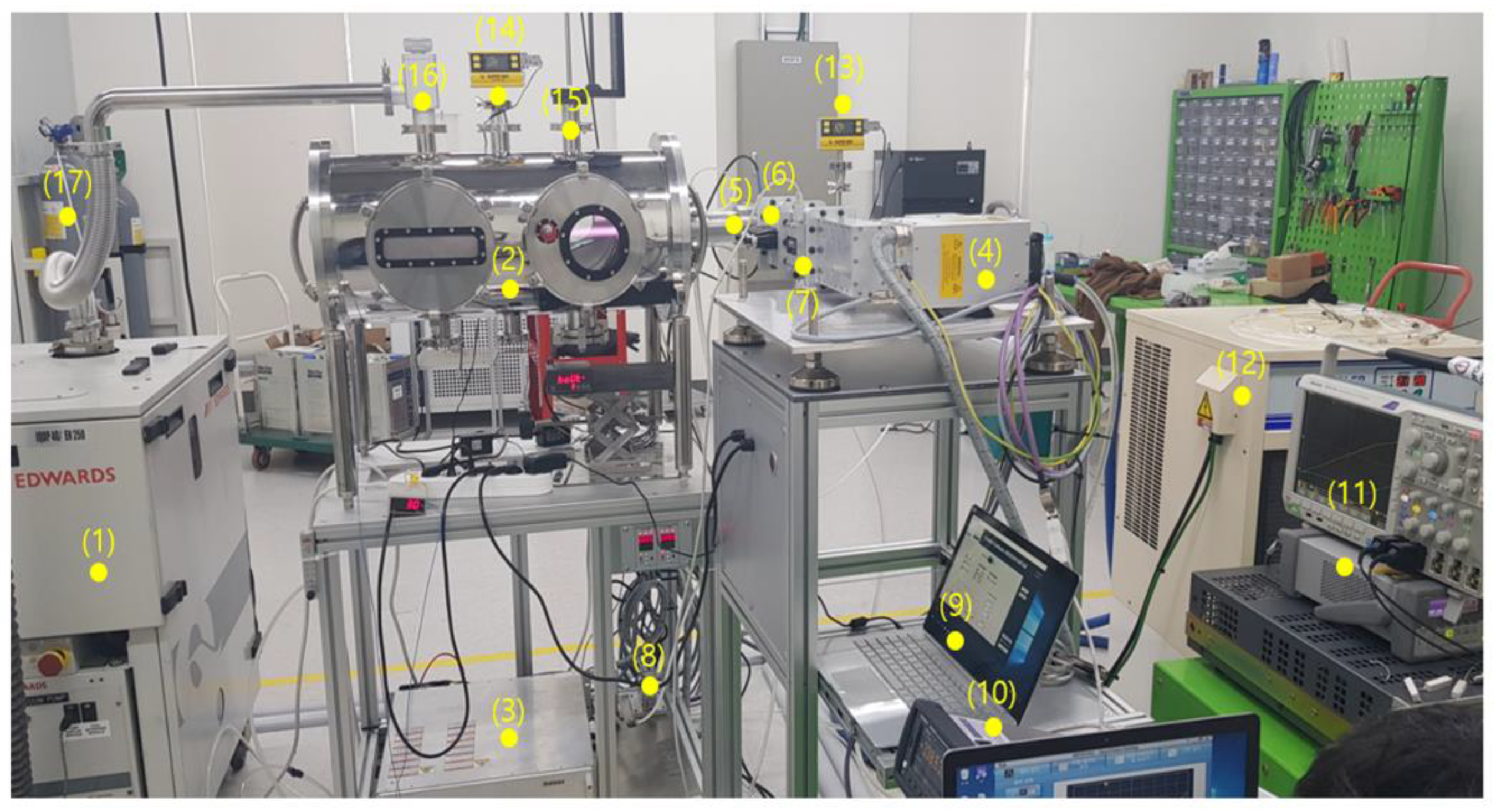
The μ-PAD system in
Figure 1 consists of several components: magnetron (Muegge, 2.45 GHz/3 kW), waveguide (WR340), microwave plasma source, oil chiller (SHINPUNG PRECISION, SPO 200T), data acquisition system (KEYSIGHT, DAQ970A), stainless steel vacuum chamber (diameter: 312.5 mm, length: 700 mm), mass flow controller (LineTech, 50 Slm), vacuum gauge (INSTRUCTECH, CVM201), and dry pump (EDWARDS, IQDP40).
The microwave plasma is generated inside a discharge quartz tube, which has a 10 mm inner diameter, 12 mm outer diameter, and length of 295 mm. Having a long discharge tube length allows the powder to have enough time to interact with the generated plasma. The 2.45 GHz microwave is fed via bidirectional power meter, 3-stub tuner, and a tapered waveguide to excite gas in the discharge quartz tube.
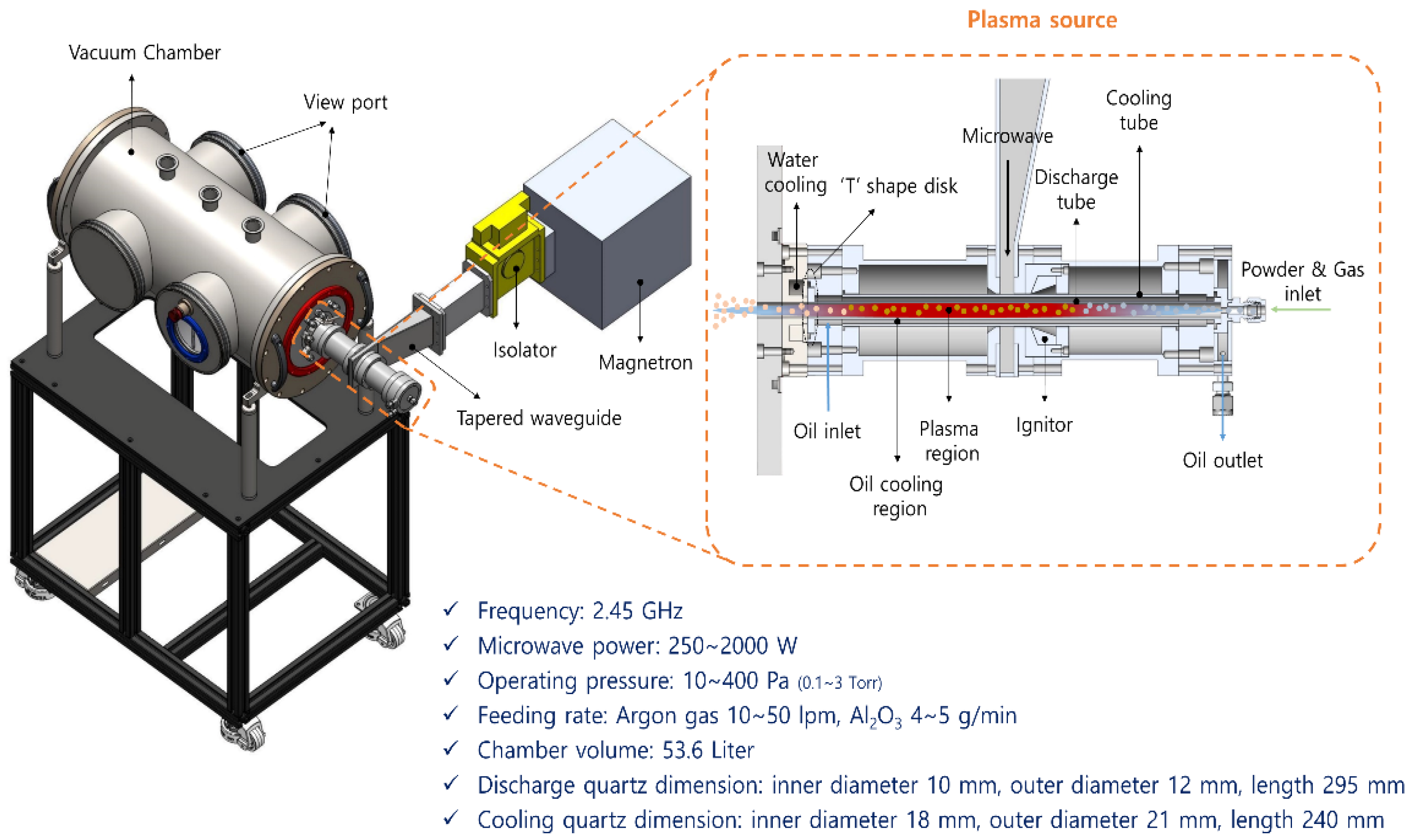
A schematic of the μ-PAD source is shown in
Figure 2. When operating for long hours the ceramic nozzle becomes easily heated by the plasma which could cause damage. Due to this issue, the μ-PAD source operates without a ceramic nozzle. In addition, a cooling tube made of quartz (inner diameter: 18 mm, outer diameter: 21 mm, length: 240 mm) is placed outside of the discharge tube to provide effective cooling. The surface wave discharge plasma generator in the μ-PAD has a dual cooling structure, in which it is not possible to use water for cooling the discharge tube. Therefore, dimethyl silicone oil (Shinetsu, KF96-100CS) is used as a coolant, which causes less microwave heating (dielectric constant 2.74 at 50 kHz) compared to water so that stability of long-term operations is ensured. It also has excellent properties such as heat resistance, electrical properties, and is chemically inert and stable. Silicon oil circulates through an oil chiller so that the surface of the discharge tube is directly cooled.
At one end of the quartz discharge tube, there is a ‘T’-shaped disk and an O-ring that is located away from the hot plasma. In addition, a zero-length flange is installed to cool the ‘T’-shaped disk and O-ring. This part is cooled by water.
When plasma ignition is not possible under severe conditions, this occurs sometimes when the Al2O3 powder and Ar gas are supplied at the same time, a high-voltage DC ignition system (Neon transformer, 15 kV) can be applied by an indirect method from outside of the discharge tube.
The AD method uses the pressure difference between atmospheric and vacuum with the nozzle to further cause acceleration for aerosol deposition. In contrast, the μ-PAD has no nozzle so that aerosol deposition is conducted only by the pressure difference and plasma energy.
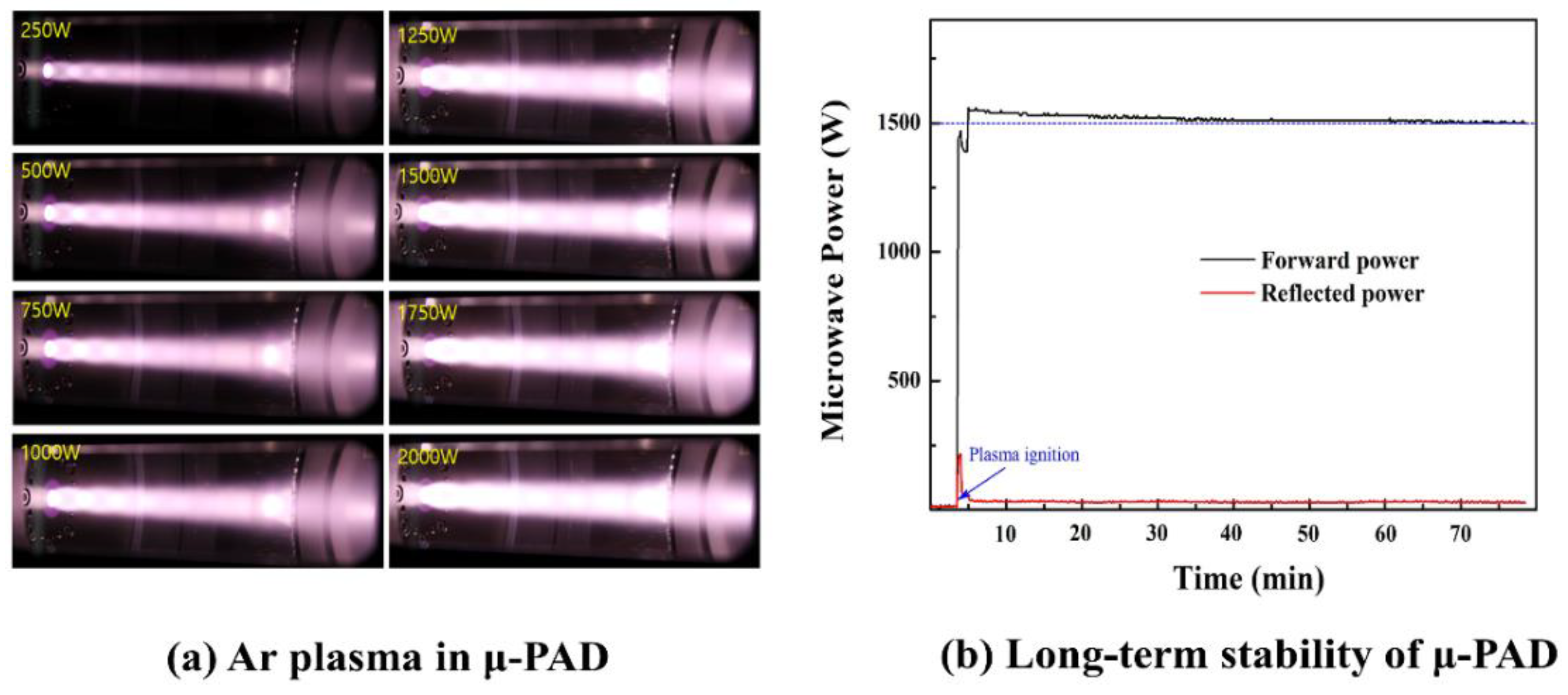
The μ-PAD source operates at a wide pressure range from 0.1 to 760 Torr. To match the operation pressure of 1 to 10 Torr used in the industry, μ-PAD pressure is set at 1.7 Torr with Ar gas flow at 10 slm, while microwave power varies from 250 to 2000 W. Pictures of Ar plasmas are shown in
Figure 3a for eight different microwave power settings (250, 500, 750, 1000, 1250, 1500, 1750, and 2000 W) while maintaining a constant pressure at 1.7 Torr. All pictures have been captured with the same exposure time.
As microwave power is increased more, it is readily noticeable that the plasma emission becomes brighter as the width and length become longer. This is mainly due to the increase in plasma density and temperature according to more microwave power.
Figure 3b shows a long-term continuous operation test at a microwave power of 1.5 kW and operating pressure of 1.7 Torr. Stability was successfully confirmed during continuous operation of 80 min or more. This is given by comparing the forward and reflected power measurement of the microwave. Having good stability is an essential element for the industrial application of the μ-PAD source.
4. Characteristics of μ-PAD
In this study, coating results of μ-PAD are compared with AD that is applied at the actual on-site coating process of semiconductor etching device parts. Operating conditions for AD are mostly optimized by the working distance and pressure, while μ-PAD is optimized by the gas pressure and the applied microwave power. Therefore, each method requires operation under different conditions to achieve the optimal deposition rate and film quality so that the characteristics between AD and μ-PAD can be compared. For both AD and μ-PAD, the condition that has the highest deposition rate and coating thickness was selected to be the optimized condition. While conducting various experiments for each condition (pressure, distance to the sample, powder supply, and microwave power) the thickness of the coating film was measured immediately. This way, the experimental condition with the highest deposition rate is found.
The experimental optimal operation parameters of AD and μ-PAD are shown in
Table 1. The Al
2O
3 powder used is α- Al
2O
3 (>99.9%, Showa Denko Co., Tokyo, Japan), where the same type of powder was applied on both AD and μ-PAD. The Al
2O
3 powder is fed at a rate of 4 g/min having a particle size of 0.5 μm. For AD, the carrier gas uses N
2 of 15 slm supplied to the AD nozzle that accelerates the Al
2O
3 powder. For μ-PAD, Ar is used as the discharge gas supplied at 30 slm to generate plasma. The working pressure of AD is at 0.15 Torr, whereas μ-PAD is at 0.33 Torr with a microwave power of 1.5 kW supplied simultaneously.
The working distance between the nozzle and the substrate is 10 mm for AD, and 50 mm for μ-PAD. The substrate moves at an identical scan speed of 100 mm/sec for both AD and μ-PAD while being coated by the Al2O3 powder. For μ-PAD, after supplying Ar gas, the microwave is turned on for ignition. Afterward, the Al2O3 powder is supplied to the μ-PAD source for coating.
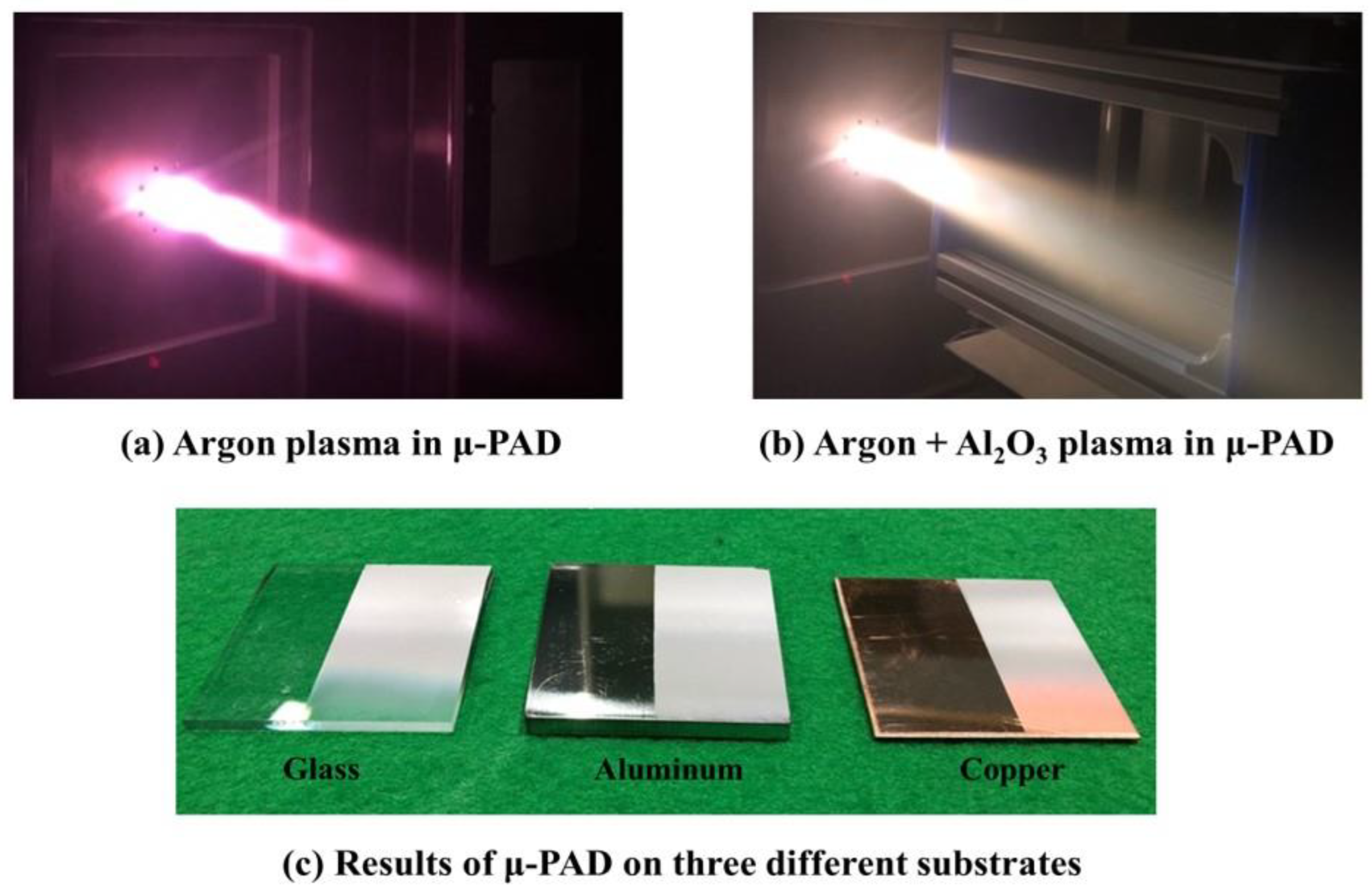
There is an apparent color change of the Ar plasma when the Al
2O
3 powder is supplied as shown in
Figure 4a,b. The Al
2O
3 films have been successfully coated by the μ-PAD method on three different substrates: glass, aluminum, and copper in
Figure 4c.
Characteristics of the coated ceramic film are compared in
Table 2. The total thickness of AD is 11 μm/11 times coatings, while the thickness of μ-PAD is 96 μm/8 times coatings of the Al
2O
3 film. It is shown that the AD method has a limit on forming thick films of 30 μm or more. On the other hand, it is possible to obtain a 96 μm thick ceramic film with μ-PAD. In addition, the coating rate of AD is 1 μm per each time while μ-PAD is at 12 μm. This shows that the coating rate of μ-PAD is about 12 times higher than AD.
In comparison with the HAD method that produces plasma by RF of 6 kW, the HAD film characteristics are shown to be similar to AD. HAD also has similar features to AD such as having a low deposition rate and thickness limitation. On the other hand, μ-PAD can operate at a lower microwave power of 1.5 kW. However, the coating film properties appear to be less than AD as shown in
Table 2.
The μ-PAD method does indeed demonstrate a fast deposition rate and thicker film than AD, which could be attributed to the long plasma volume so that the ceramic power is effectively activated. In μ-PAD, while the ceramic powder passes through the microwave plasma, agglomeration of the powder is reduced due to numerous collisions with high-density electrons and ions, so that the fine powder status is maintained until it reaches the substrate. The film is coated in the form of a fine powder due to less agglomeration by high-density microwave plasma. It is thought that this process allows a high deposition rate and thick coating film formation [
22,
23]. Furthermore, in μ-PAD, the internal discharge tube is circular, has a diameter of 10 mm, and has a cross-sectional area of 78.5 mm
2. This is 19 times larger than the cross-sectional area (0.4 × 10 mm
2) 4 mm
2 of the AD nozzle end, so the powder becomes difficult to accumulate in the μ-PAD that is without a nozzle. In addition, as the powder passes through the high-density microwave plasma section of about 300 mm in length (long residual time compared to HAD), the moisture on the powder surface is removed due to the preheating effect of the powder by frequent collisions with electrons and ions of the plasma. This also causes the μ-PAD to have a higher deposition rate and a thicker coating film than AD [
24]. On the other hand, AD uses the nozzle for acceleration, which causes the ceramic powder to severely agglomerate. This tends to act as a cushion for reducing the kinetic energy of the incoming powder upon impact so that the film thickness is limited [
22,
23]. In addition, AD shows that the agglomeration of ceramic powder occurs due to the adsorption of moisture when there is no preheating process [
24].
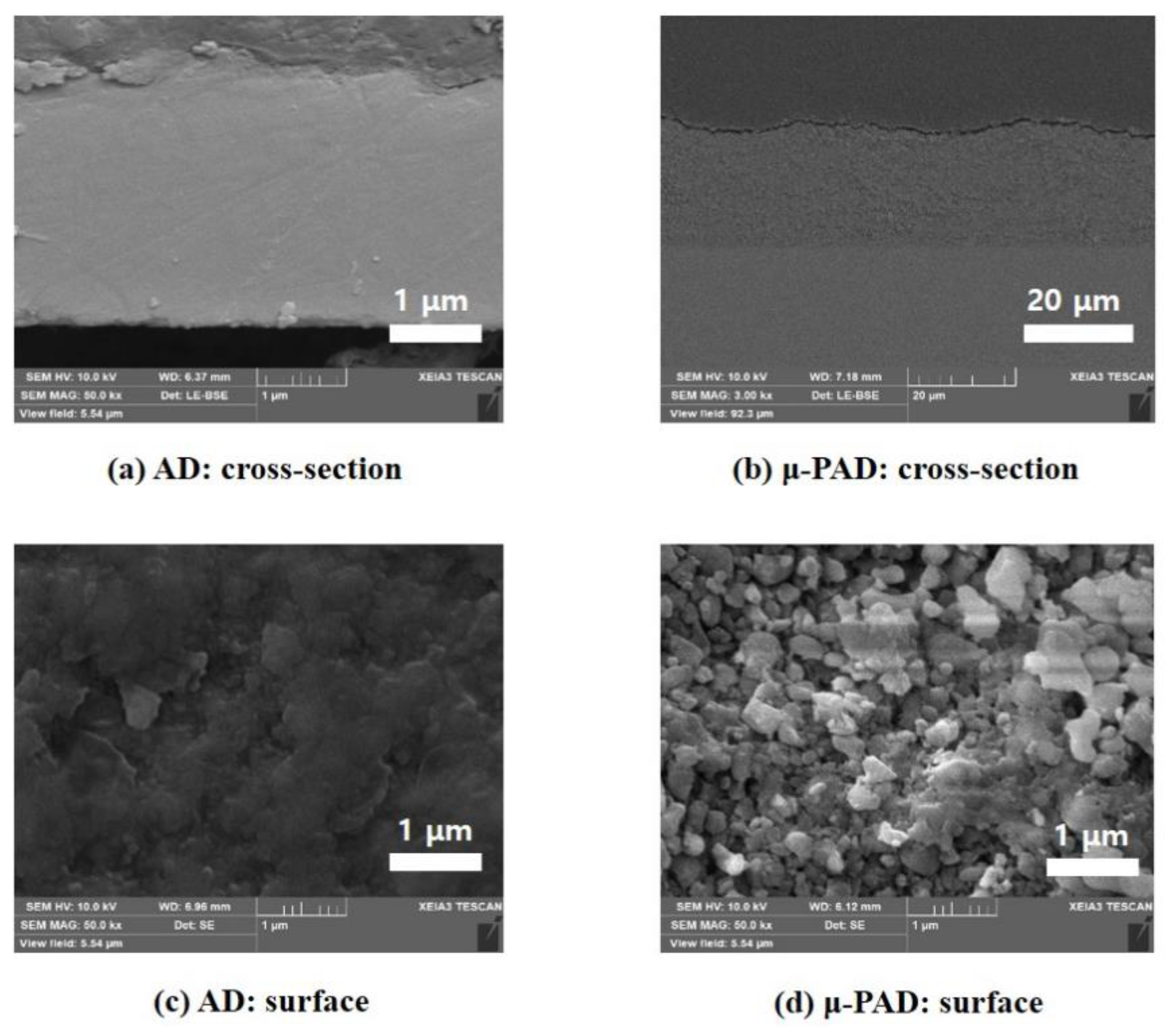
The coating film hardness is lower for μ-PAD at 380 HV, while AD is at 1200 to 1400 HV. Therefore, the hardness of the AD coating film is approximately three times higher. The porosity of the AD coating film is 0.5% or less, and the porosity of the μ-PAD coating film is 8.8%. The tensile adhesion strength of the AD coating film is 60 MPa, and the μ-PAD coating film is 38 MPa. The withstand voltage of AD coating film is 120 V/μm, while μ-PAD coating film is about half at 67 V/μm. The surface roughness (Ra) for AD is 0.35 μm, while μ-PAD is at 2.07 μm, which is six times larger, which is similar to the roughness of APS. In summary, hardness, porosity, adhesion, withstand voltage, and surface roughness characteristics of the μ-PAD coating thin film are insufficient when compared with AD.
Relatively large size particles enter the substrate at high speed for AD, due to frequent agglomeration, causing plastic deformation and the formation of high dense film. On the other hand, for μ-PAD, particles pass through the plasma at a relatively slow speed so that it causes less agglomeration. Therefore, low-density films are formed but instead have a high deposition rate.
FE-SEM (Nanosem450, FEI) show images of the cross-section and surface of the Al
2O
3 film by the AD and μ-PAD methods, respectively, in
Figure 5. The cross-sectional images in
Figure 5a,b shows that the AD coating film is denser than μ-PAD. This explains why μ-PAD films display lower properties (hardness, porosity, adhesion, withstanding voltage, and surface roughness) than AD films.
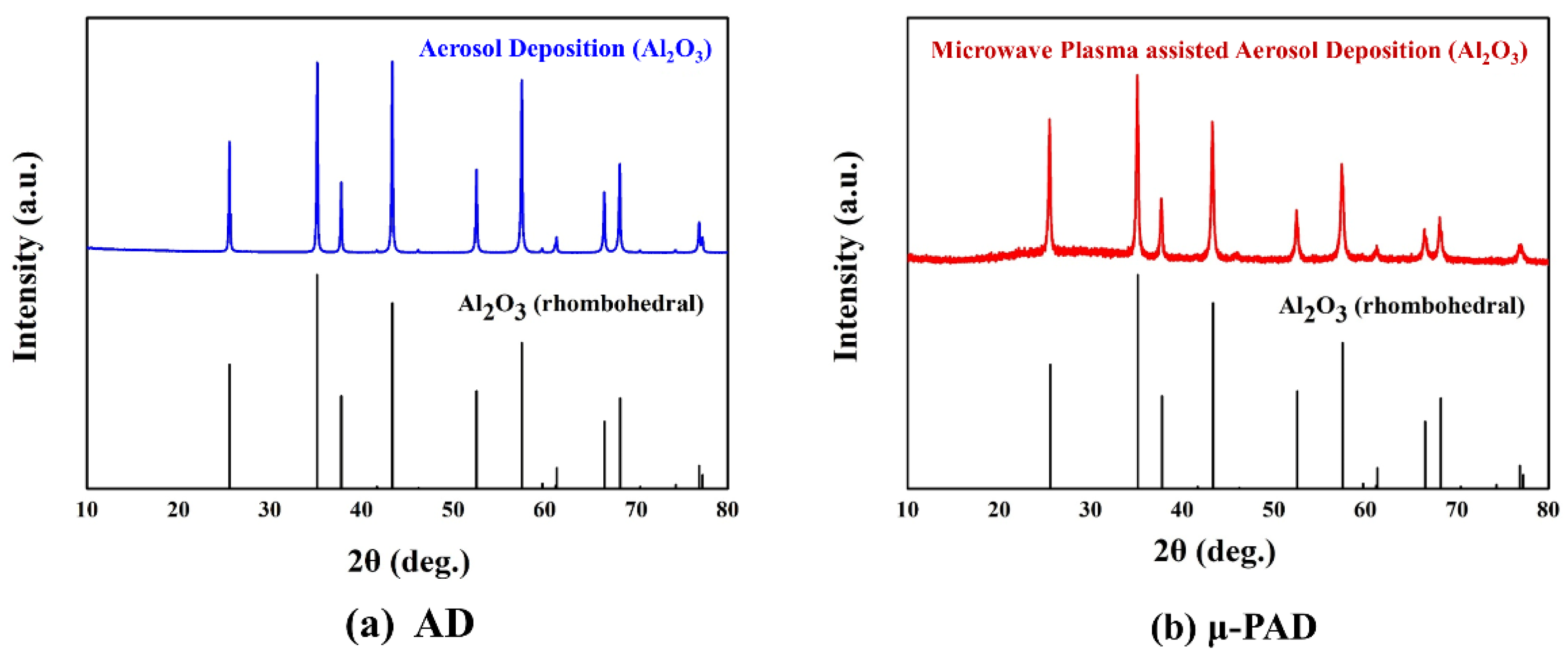
The X-ray diffraction (CuKa, Smartlab, RIGAKU) pattern of the Al
2O
3 coated film on the glass substrate is displayed in
Figure 6a,b. With the μ-PAD coating film, the almost identical structure of the Al
2O
3 raw powder without phase transition is observed in the XRD analysis. However, XRD data show no signs of the γ-Al
2O
3 phase. If it were melted, the metastable γ-Al
2O
3 phase should have appeared [
25]. Therefore, μ-PAD causes no phase transition during the interaction of the plasma and Al
2O
3 powder.
This differs from the commonly used plasma coating (APS, SPS) film. The μ-PAD operates at a low-vacuum and low-temperature plasma condition (1 Torr, microwave power 900 W, Ar gas temperature 1643 K, electron density 22 × 10
17 m
−3, electron temp 3.7 eV [
21]), which causes fewer problems associated with phase transition when compared to the atmospheric high-temperature plasma coating methods. In addition, in
Figure 6, it is observed that the peak width (FWHM) of μ-PAD is slightly increased compared to AD. The broadened XRD peak (μ-PAD) indicates the presence of finer microstructures. As particles pass through the μ-PAD, many collisions with electrons and ions occur which reduces agglomeration. The coated film is deposited and observed by the broadened peak of the XRD data. On the other hand, AD accelerates the particles through the nozzle so that agglomeration severely occurs. Thus, a sharp peak on the XRD data appear in contrast.
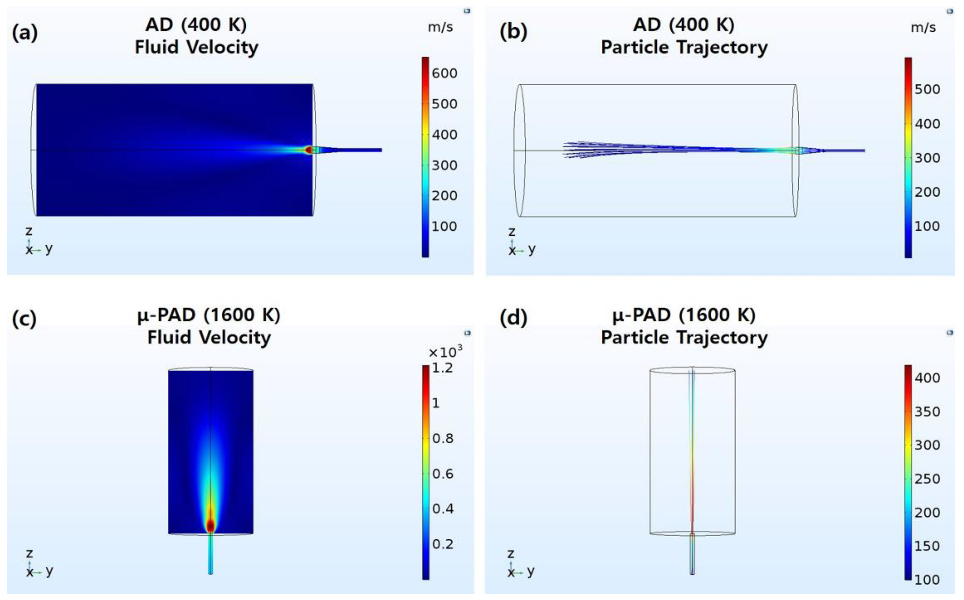
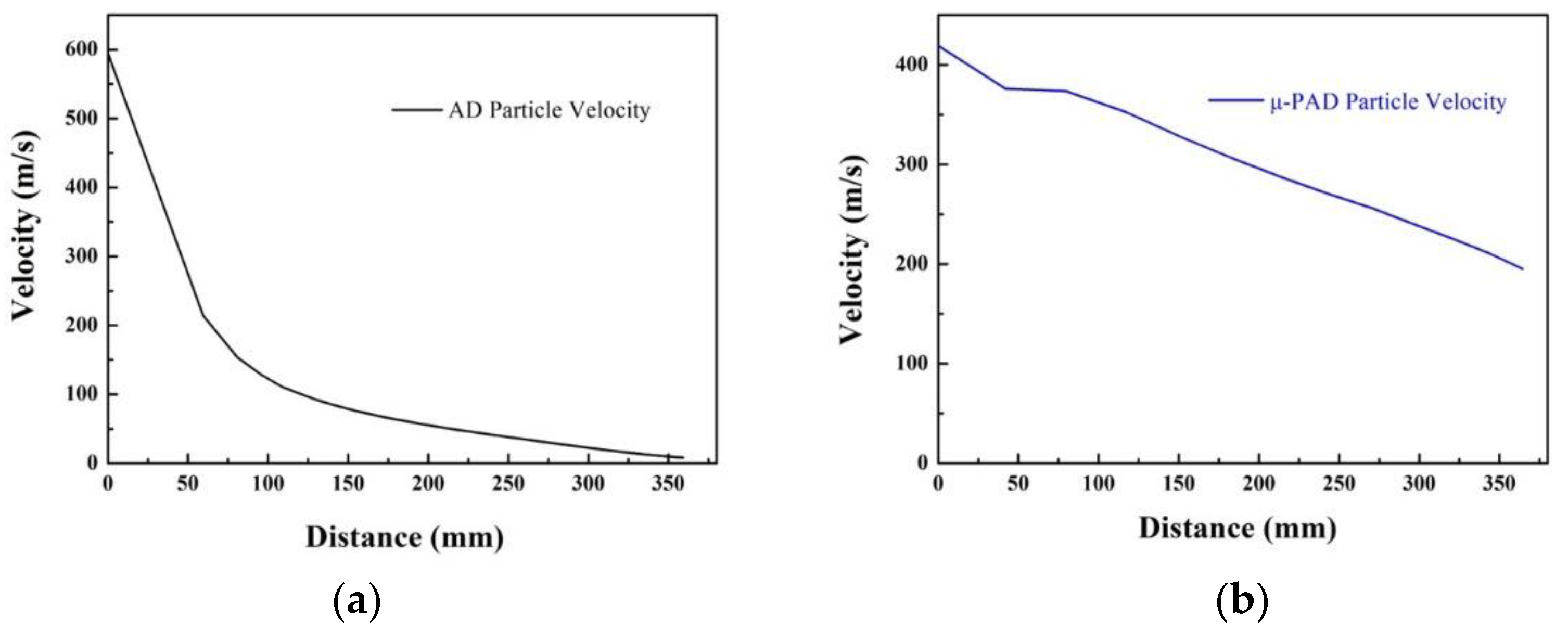
A model study using 3D simulation was carried out to analyze the turbulent fluid flow and particle trajectories for the AD and μ-PAD methods. The High Mach Number Flow Module contained in the commercial software COMSOL Multiphysics (V. 5.3a, COMSOL Multiphysics, Stockholm, Sweden) was utilized [
26]. Specific formulas and conditions can be found in the following paper [
27]. The 3D simulation results are shown in
Figure 7 and
Figure 8. It is assumed that there is no collision between particles, and it is assumed that the powder particles move along the dragging force of the gas fluid. The AD with the nozzle accelerates particles to 594 m/s, while μ-PAD accelerates to 419 m/s. However, the particle speed dramatically decreases after passing through the nozzle for AD, while the μ-PAD seems to maintain its speed up to a certain distance that eventually decreases. It could be observed that particles continuously gain energy by the plasma jet generated in the μ-PAD and maintain its velocity. Therefore, AD is sensitive to the distance of the film sample, while μ-PAD is less sensitive.


 ,
, 


