Article

Oxidation Resistance of γ-TiAl Based Alloys Modified by C, Si and Y2O3 Microdopants

The Laboratory “In Situ Diagnostics of Structural Transformations”, National University of Science and Technology «MISiS», Leninsky Prospect, 4, 119049 Moscow, Russia
*
Author to whom correspondence should be addressed.
Ceramics 2022, 5(3), 389-403; https://doi.org/10.3390/ceramics5030030
Submission received: 1 July 2022 / Revised: 25 July 2022 / Accepted: 29 July 2022 / Published: 2 August 2022
(This article belongs to the Special Issue Ceramic Processing and Sintering)

Abstract

:
This work aimed to study the oxidation resistance of γ-TiAl based alloy, doped with small concentrations of carbon, silicon, and yttrium oxide in air at 800 and 1100 °C for 30 h. The TNM-B1 alloy samples were produced via high-energy ball milling, self-propagating high-temperature synthesis, and hot isostatic pressing techniques. The microstructure, oxidation kinetics at 800–1100 °C, scale structure, and oxidation mechanism were studied. The oxidation of alloys modified with carbon and silicon at 1100 °C was characterized by the formation of a three-layer coating. The Y2O3 modified alloy performed the greatest oxidation resistance at 1100 °C and promoted the formation of a dense Al2O3 interlayer.

Graphical Abstract

1. Introduction

TiAl alloys have low density and excellent mechanical properties at high temperatures and are considered among the best candidates for turbine blades used in gas turbines and aircraft engines [1,2]. However, poor oxidation resistance at high temperatures (up to 900 °C) impedes further use of these alloys. Many efforts have been made to overcome this challenge such as alloying and nanomodification [3,4,5]. From the perspective of cost control, alloying is the most extensively used method.
TNM alloys doped with niobium and molybdenum have been created due to the advancement of TiAl-based alloys. Both compounds improve high-temperature oxidation resistance [6,7]. They can enhance oxidation resistance by inhibiting the formation of undesired TiO2 oxide layers [8] and improve plastic deformation behavior at room temperature by lowering the energy of stacking defects [9,10,11]. The inclusion of niobium and molybdenum raises the activation energy of diffusion in γ-TiAl and α2-Ti3Al, increasing the creep resistance of the alloys [10,12,13].
The next development step was the creation of TNM-B1 alloys doped with 0.1% B [14,15] and TNM + alloys including C and Si micro concentrations [16,17,18]. Boron reacts with titanium to form scattered TiB2 particles, which provide grain refinement to the alloy and, as a result, increase its strength at room and high temperatures. Improving the TNM-B1 group alloys to enhance the performance characteristics of aerospace engines is a considerable challenge. The alloying of these alloys with micro-concentrations of C, Si, and Y2O3 is one of the most promising directions in this field. Several studies [19,20,21,22,23,24,25] have shown that these additives improve the mechanical characteristics at high temperatures. C and Si additions can be dissolved in the γ-TiAl + α2-Ti3Al matrix, limiting diffusion processes. They can also form the dispersed carbides Ti3AlC, Ti2AlC, and Ti5Si3 silicide, impeding dislocation migration under load. The TiAl-based alloys containing Y2O3 show excellent strength characteristics up to 800 °C [16,17,18]. Ultrafine Y2O3 particles segregate between lamellas along the γ-TiAl and α2-Ti3Al grain boundaries in alloys with a fully lamellar structure (FL-structure) and serve as nucleation sites, providing grain refinement of the alloy.
TiAl-based alloys, doped with C, Si, and Y2O3, have proven their superior high temperature strength and creep resistance, but some incomplete data on their oxidation resistance can be found. The protection mechanism utilized by the carbon addition consists of impeding either the intracrystalline diffusion by dissolved carbon atoms [26] or the intergranular diffusion of oxygen by the TiC carbide nanoparticles or Ti2AlC and Ti3AlC2 MAX-phases [27,28]. Silicon is considered as the most beneficial element for improving the oxidation resistance of TiAl-based alloys, since it forms SiO2 oxide with low oxygen solubility, and also suppresses the growth of rutile TiO2 in the oxide scale. However, it should be noted that the most outstanding results were obtained at sufficiently high Si concentrations (5–13%) [29], which lie far beyond the known limits for effective strength and creep resistance improvement. To achieve a combination of high mechanical properties and oxidation resistance, it is advisable to protect the surface of TiAl-based alloys with coatings of TixSiy [30,31], TiAlSiN [32,33], Al–Si [34,35,36], and others, as obtained by magnetron sputtering and ion implantation. The effect of Y/Y2O3 additives on the oxidation resistance of TiAl-based alloys is well-covered. In [21,37,38], the positive effect of Y2O3 in the oxidized layer was explained by the fact that these particles block the grain boundary migration of oxygen atoms as well as the formation of a stronger oxidized layer due to the pinning of TiO2 and Al2O3 layers with Y-containing phases.
The potential of each of the above-mentioned additives for improving oxidation resistance has been proven by many works. However, there is a lack of data on their comparison with each other, which is possible only when using alloys with an identical chemical composition and microstructure.
This work aimed to study the oxidation resistance of a powder metallurgy manufactured Ti–43Al–4Nb–1Mo–0.1B alloy with an equiaxed microstructure, doped with small (0.2–1.5 wt.%) concentrations of C, Si, and Y2O3. The microstructure, oxidation kinetics at 800–1100 °C, scale structure, spallation resistance, and oxidation mechanism were systematically studied.

2. Materials and Methods

2.1. Initial Powders

Titanium (Polema Co., Tula, Russia, average particle size 15–20 µm), aluminum (“Polema Co.”, average particle size 10 µm), niobium (SpecMetallMaster Co., Moscow, Russia, average particle size 40 µm), molybdenum (“Polema Co.”, average particle size 5 µm), and boron powders (Ermakchim Co., Moscow, Russia, average particle size 0.2 µm) were used as initial materials for the basic γ-TiAl based TNM-B1 alloy. Carbon black (Ekopol’za, Astrakhan, Russia, P80, specific area 15 m2/g, mass concentration—0.2%), ground silicon single crystals (LLC ‘Telekom-STV’, Zelenograd, Russia, average particle size 15 µm, mass concentration—1.5%), and Y2O3 powder (Plasmatherm, Moscow, Russia, average particle size 0.2 µm, mass concentration—1.5%) were used as the dopants. Hereafter, the corresponding alloys were signed as 0.2C, 1.5Si, and 1.5Y2O3.

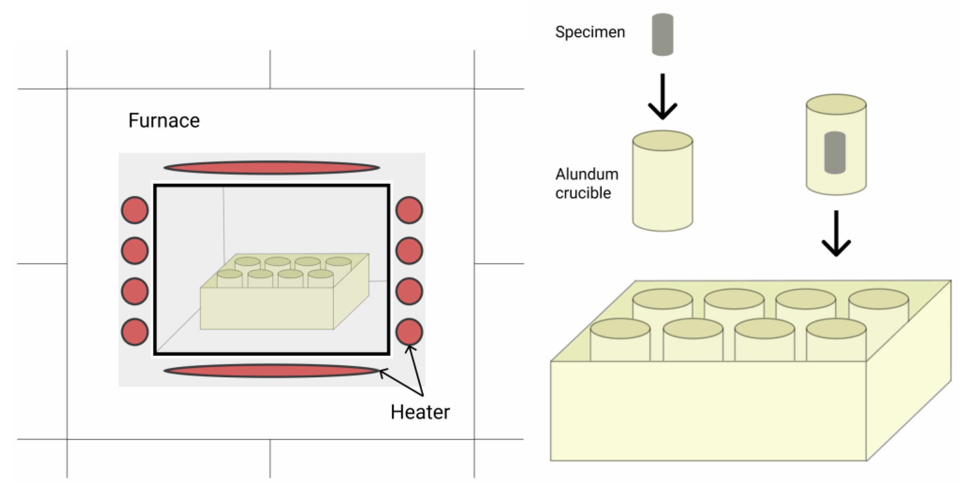
2.2. Manufacturing and Investigation Methods

The alloys were manufactured according to technological route, described in detail in previous research [39]. It contained three main operations: high energy ball milling (HEBM) and self-propagating high-temperature synthesis (SHS) were used to prepare γ-TiAl based powders followed by hot isostatic pressing (HIP) for powder consolidation.
HEBM was carried out in order to obtain the uniform distribution of components in the powder mixture in an argon atmosphere in an Activator-4M planetary ball mill (Activator, Russia) with steel grinding the media and ball to a powder mass ratio of 15:1. The SHS method was used to obtain the required phase composition of the powder. To start the SHS process in the thermal explosion mode, pre-pressed powders were placed in a tube-type furnace set to 900 °C. A thermocouple placed next to the pressed bars was used to control the temperature. The SHS process was conducted in an inert atmosphere with an argon flow rate of 10 mL/min. Sintered bars were ground to achieve a grain size of less than 65 μm and distribution quantile value D50 about 32 μm.
Compact samples were obtained by hot isostatic pressing (HIP) of the powder mixtures in titanium capsules at a temperature of 1250 °C for 2 h. No special heat treatment was carried out after HIP in order to maintain a two-phase near-globular microstructure of the alloys. Oxidation cylindrical specimens of h = 4 and diameter d = 6 mm were cut from the as-HIPed workpieces using wire electrical discharge machining. The oxidation of the specimens’ surfaces were polished with abrasive paper 2400 mesh and ultrasonically washed with isopropyl alcohol. Three specimens of each alloy were measured simultaneously to assess the repeatability and scatter of the samples.
Oxidation experiments were carried out in a muffle furnace with an air atmosphere for 30 h at 800 °C and 1100 °C. The first temperature was chosen as it is typical for the operating of TiAl-based turbine units—the main application field of TiAl-based alloys. Oxidation experiments at 1100 °C were meant to demonstrate the potential of the C, Si, and Y2O3 modified alloys for use in more extreme conditions and to make the difference in oxidation kinetics more apparent.
To avoid the spalled oxide scale from leaving the crucible and to ensure proper interaction between the specimens and air, the specimens were kept in alundum crucibles protected by a corundum slip with small gaps. A schematic illustration of the oxidation test is shown in Figure 1.
The crucibles were placed in the center of the furnace to ensure a constant temperature. The weights of the specimens were measured every 15 min during the first 1 h of the oxidation experiments using a high-precision (0.1 mg) electronic balance (A&D, Tokyo, Japan), after which the measuring period was 1 h. The measurement period was 5 h after completing 5 h of exposure. At each measure, the crucibles with the specimens were removed from the furnace and air cooled for around 0.5 h to room temperature before being weighed. After the measurement, the samples in the crucibles were again put back into the working furnace.
An additional experiment on the oxidation annealing of samples, consisting of Y2O3 particles and the main oxide components (Al2O3 and TiO2), was carried out at a temperature 1100 °C. This allowed us to reveal the Y2O3 phase stability under oxidation conditions and the interaction direction in the presence of Al2O3 and TiO2.
After the oxidation tests, the phase composition of the oxide scale was studied by X-ray diffraction analysis (XRD) on a D2 PHASER diffractometer (Bruker AXS GmbH, Karlsruhe, Germany) using Cu radiation in the scattering angle 2θ = 20°–110° range, step 0.02°, and an exposition time of 0.6 s. The structure of the as-HIPed and oxidized specimens was investigated in cross-section polished samples using an S-3400 N scanning electron microscope (Hitachi, Tokyo, Japan) fitted with a NORAN energy dispersive spectrometer.
The fine structure of the oxide scale after annealing was analyzed by transmission electron microscopy (TEM) using a JEM 2100 microscope (Jeol, Tokyo, Japan), equipped with an X-MAX 80 EDX detector (Oxford Instruments, Abingdon, UK). A lamella with dimensions of 5 × 3 µm was produced using a focused ion beam technique using a Scios dual-beam microscope (Field Electron and Ion Company, Hillsboro, OR, USA).

3. Results and Discussion

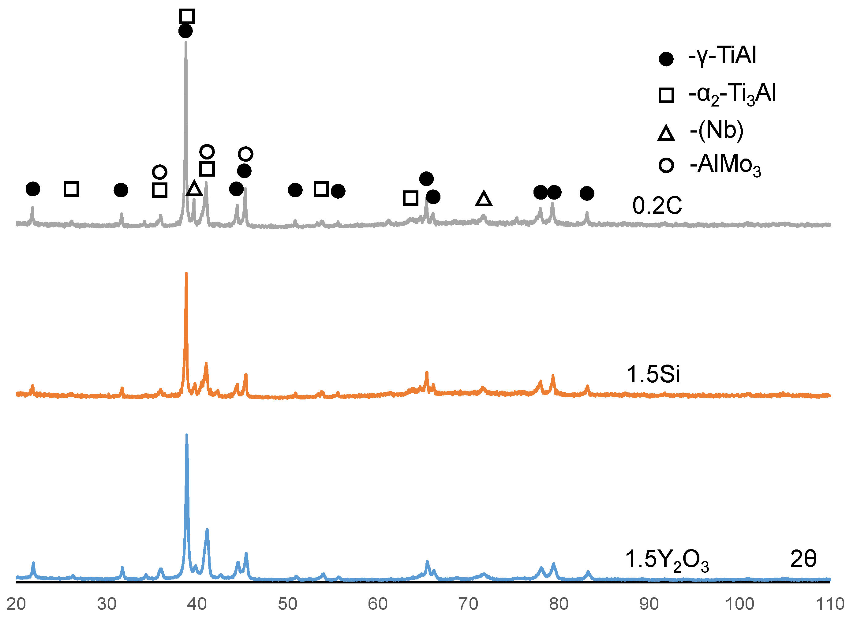
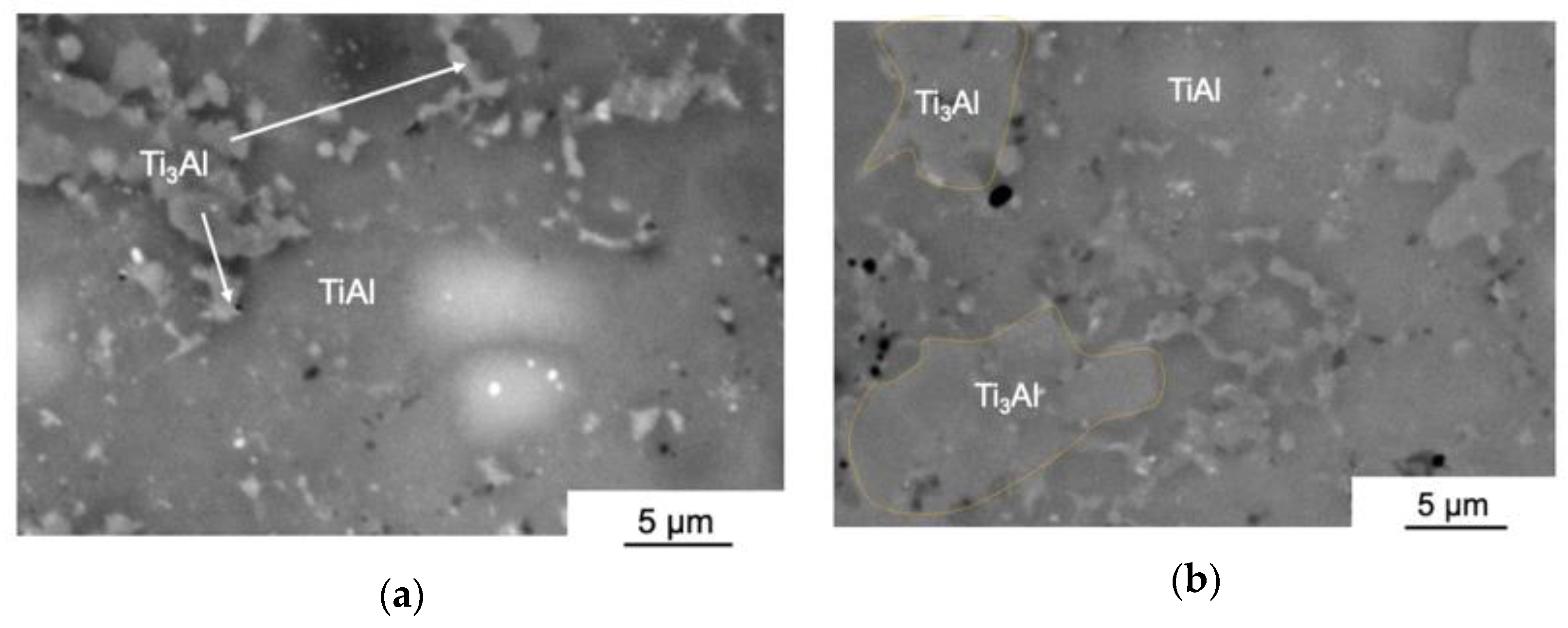
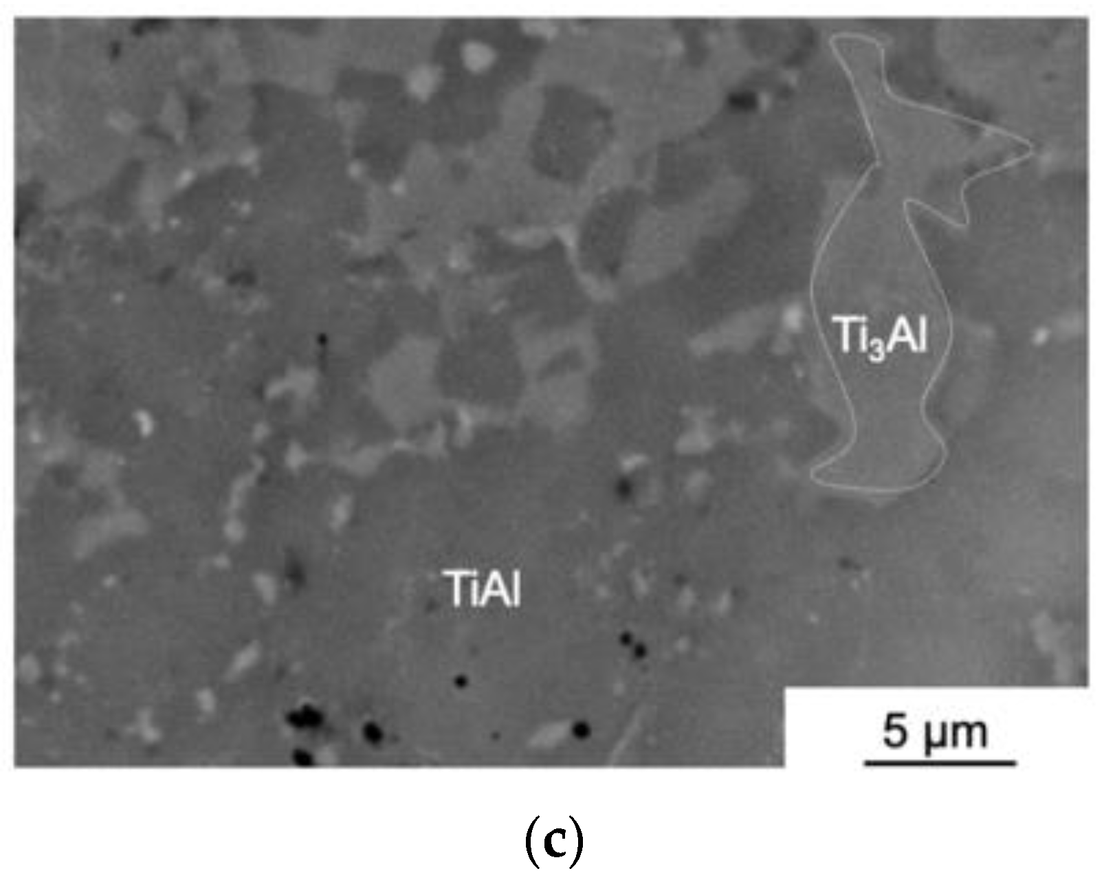
3.1. The Structure and Phase Composition of as-HIPed Samples

The investigated TiAl alloys had an irregular two-phase structure and consisted of grains of γ-TiAl and α2-Ti3Al. Figure 2 shows the images of typical structures of the samples with each dopant after HIP. The microstructure of the studied alloys is not typical for common TiAl-based alloys produced by casting (leading to the formation of a duplex or lamellar structure). They inherited the microstructure of the powder particles after HEBM and SHS [39]. This was preserved due to consolidation at low temperature, below the β-Ti field in the Al–Ti phase diagram, and the lack of special heat treatment.
The average grain size of γ-TiAl was 12.5 μm and that of α2-Ti3Al was 5 μm. The major alloying components—niobium and molybdenum—were dissolved in the matrix during the HEBM process of preparing the powder mixture. Nevertheless, there was a limited number of grains in the structure of all alloys with a higher proportion of these components, which was indicated by the XRD method as a solid solution of molybdenum in niobium (Nb) (Figure 3). As carbon and silicon were dissolved in the γ-TiAl and α2-Ti3Al phases, no carbides or silicides were found in the 0.2C and 1.5Si alloys (Figure 3). At the HIP temperature, yttrium oxide Y2O3 had little interaction with TiAl and took the form of submicron particles that were uniformly dispersed throughout the matrix (Figure 2c).
Figure 3 shows the X-ray diffraction patterns of the 0.2C, 1.5Si, and 1.5Y2O3 alloys. Each X-ray diffraction pattern had a set of peaks typical of γ-TiAl and α2-Ti3Al. The ratio of these phases remained constant, regardless of the type of alloying addition (5:1 by weight). A solid solution based on niobium (Nb) and the intermetallic compound AlMo3 was also found in all alloys in a range of 1–3 % (Table 1).

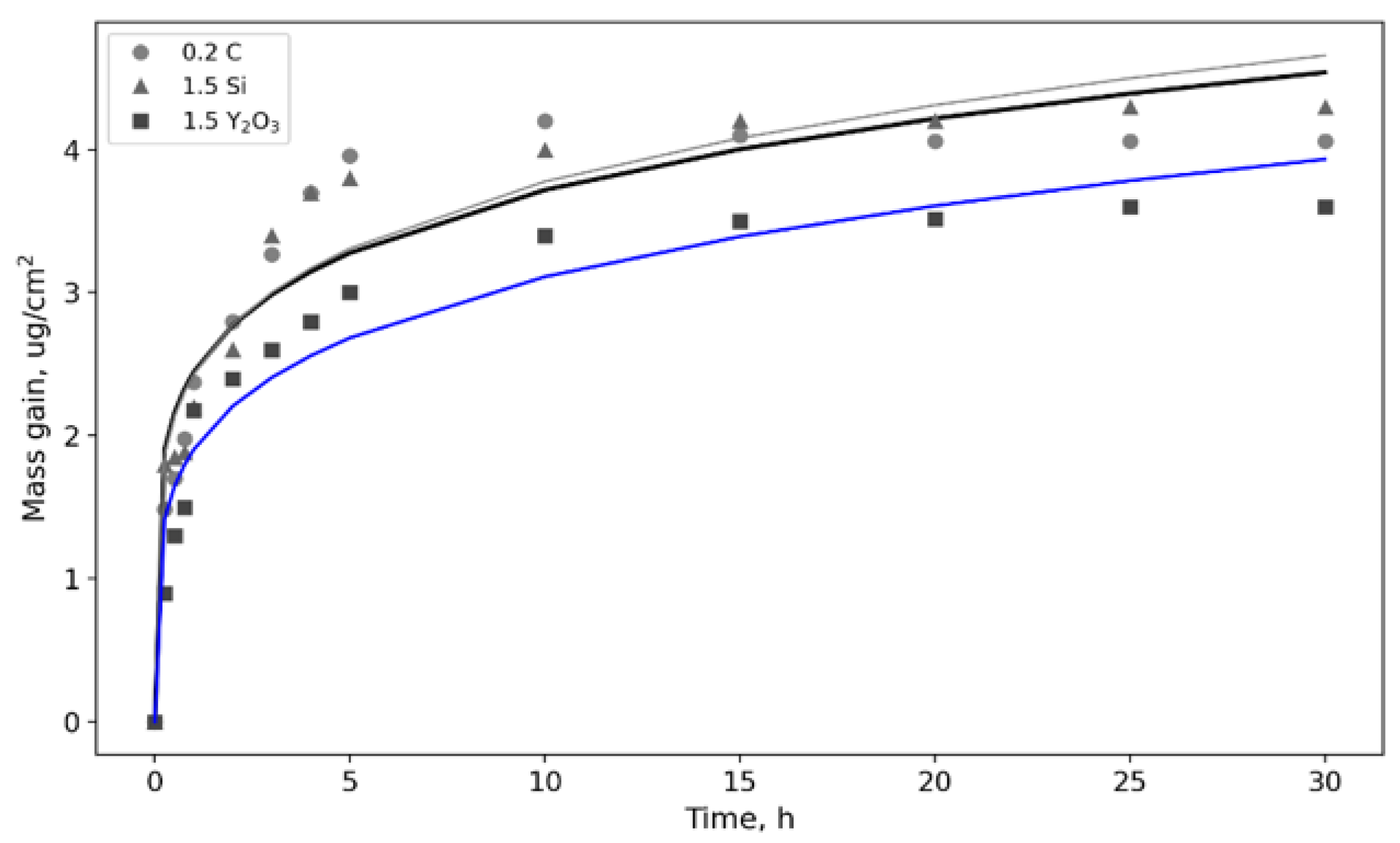
3.2. Oxidation Kinetics at 800 °C; of TiAl-Based Alloys

The oxidation kinetic curves of the alloys 0.2C, 1.5Si, and 1.5Y2O3 after isothermal annealing in an oxidizing environment at 800 °C are shown in Figure 4. The experimentally obtained curves were approximated using the power–law dependence:
ΔMn = k·t
where ΔM is the weight gain (µg/cm2); n is the power law exponent; k is the oxidation rate constant; t is the duration of the process.
For all alloys, the specific weight gain after 30 h of annealing was negligible—3.5–4.1 ug/cm2 (Table 2). The oxidation of the samples was intense during the first 2 h of annealing. After 5 h of annealing, the weight gain of the samples was modest and did not surpass 0.5 µg/cm2.
XRD and SEM were used to analyze the phase composition and the microstructure of the oxidized layer. Figure 5 shows the X-ray diffraction patterns of the alloys 0.2C, 1.5Si, and 1.5Y2O3 after oxidation resistance tests at 800 °C. All X-ray diffraction patterns revealed peaks corresponding to the γ-TiAl, α2-Ti3Al, (Nb), and AlMo3 phases in the original samples. Notably, the concentration of the α2-Ti3Al phase after annealing was considerably reduced in all of the studied samples—6–8 wt. % (compared to 17–20 wt. % before annealing). The content of the oxide phases in the surface layer was low (i.e., roughly around 5% (Table 3)). The rutile TiO2 peaks (110) at 27.2° and (101) at 2ϴ = 35.7° as well as the Al2O3 phase (104) peaks at 2ϴ = 35.1° indicate their presence.
The cross-sections of the specimens after oxidation resistance testing were investigated to determine the thickness and structure of the oxidized layer. In all cases, the oxidized layer, which had an average thickness of 2–3 µm, was mainly composed of rutile TiO2 (Figure 6). The surface of the 0.2C and 1.5Y2O3 samples had the densest oxide coatings. Long longitudinal fractures were observed at the interface between the oxide layer and the matrix in the 1.5Y2O3 alloy, resulting in partial spallation of the coating and the formation of routes for oxygen transport into the sample (Figure 6b). Al2O3 granules were found in the structure where partial spallation of the oxide layer was observed.

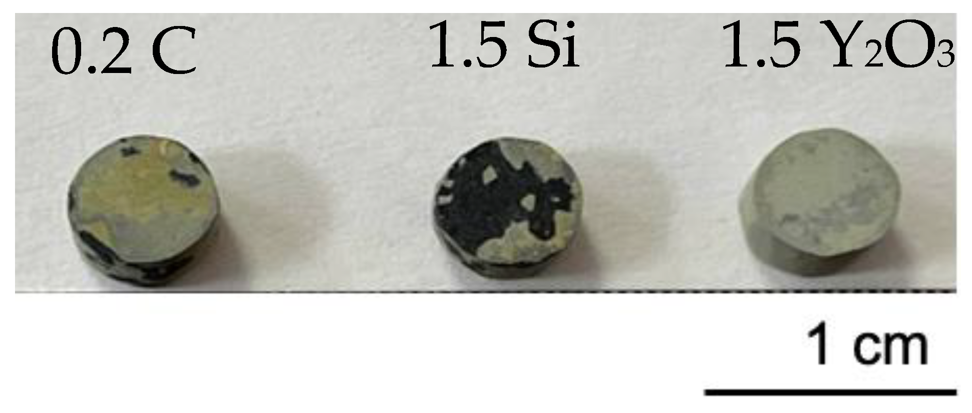
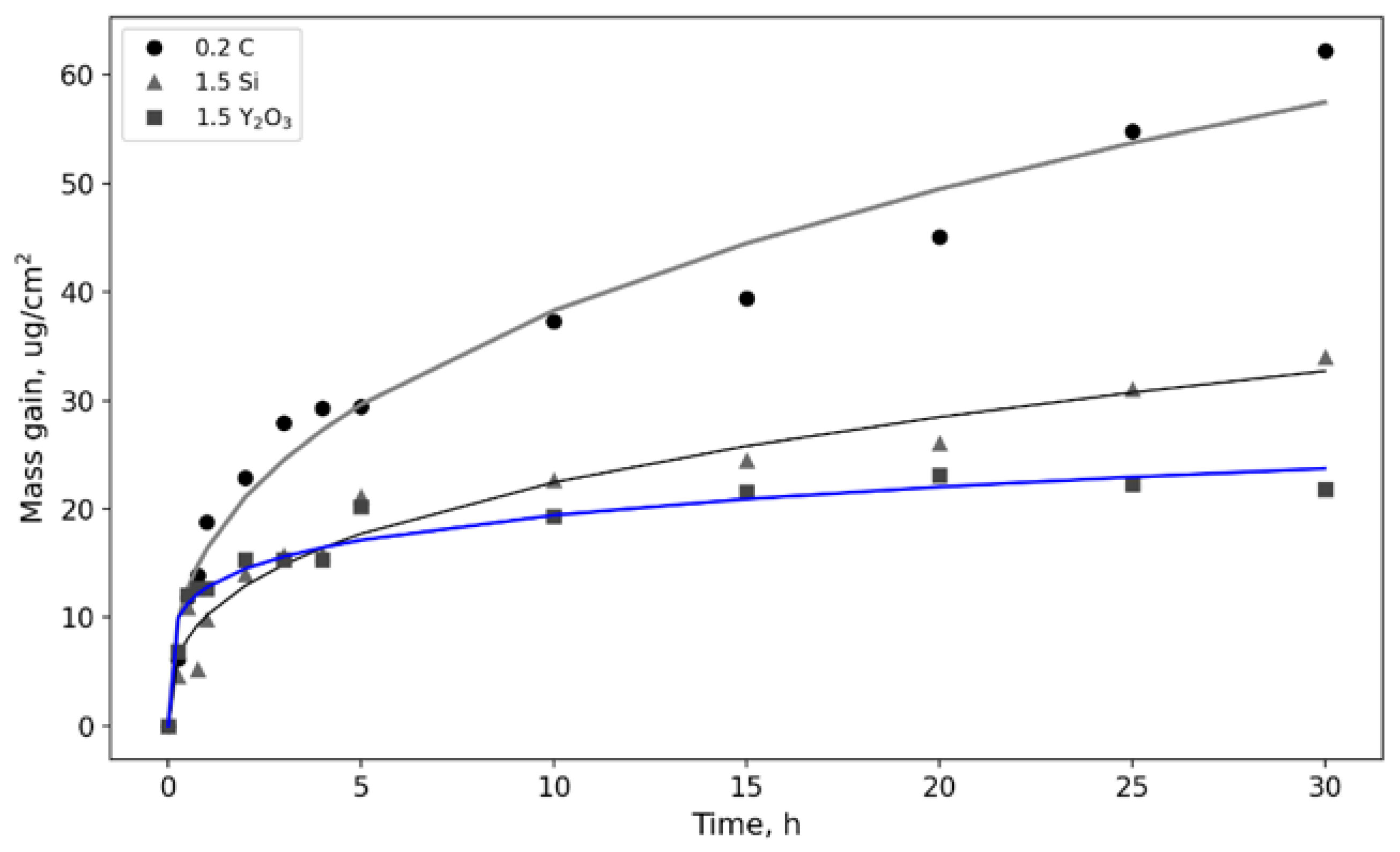
3.3. Oxidation Kinetics at 1100 °C of TiAl-Based Alloys

Figure 7 shows the appearance of the TiAl-based alloy specimens after annealing at 1100 °C. Apparently, the oxides covered a large section of the sample surface (light gray). The 1.5Y2O3 sample had the smoothest surface and no signs of the oxide layer spallation. The degradation of the coating was seen locally on the surface of the 0.2C sample. At the same time, the covering of the 1.5Si sample was nearly totally damaged, indicating its poor strength.
The oxidation kinetic curves of the alloys 0.2C, 1.5Si, and 1.5Y2O3 after isothermal annealing in an oxidizing atmosphere at 1100 °C are shown in Figure 8. The power–law dependency was used to approximate the experimental curves (1). Table 4 displays the parameters produced by approximating the experimental data, the specific weight increase of the samples after testing (M), and the average coating thickness value (h).
The behavior and oxidation tendency of the 0.2C, 1.5Si, and 1.5Y2O3 alloys changed significantly when the annealing temperature was raised. The 0.2C sample had the largest specific weight increase (61 ug/cm2), which was 1.6 times higher than the 1.5Si sample and nearly four times higher than the 1.5Y2O3 sample (Figure 8). The oxidation process was most intense during the first 3 h of annealing when a thick oxide layer developed on the surfaces of the samples. The oxidation rate was then reduced due to a delay in the diffusion processes in the sample’s near-surface layers.
During annealing at 1100 °C, the alloy 1.5Y2O3 had the lowest total specific weight growth. Its oxidation resistance was characterized by a high n-value of 5.641. The weight gain of the sample was negligible despite the annealing time of longer than 5 h. At the same time, a gradual rise in mass was seen in this area for the 0.2C and 1.5Si alloys.
The X-ray diffraction patterns of the 0.2C, 1.5Si, and 1.5Y2O3 alloys after annealing at 1100 °C are shown in Figure 9. According to the intensity of the peaks, the main phases in the surface layer were Al2O3 (approximately 50%) and TiO2 (35%). The α2-Ti3Al phase was found in all samples, although its concentration did not surpass 10% (Table 5). The presence of two different oxides with crystal structures similar to those of rutile TiO2 but with different lattice parameters a and c distinguished the 0.2C and 1.5Si alloys from the 1.5Y2O3 alloy. This was demonstrated by the splitting of all peaks related to TiO2 (Figure 9, angles of 27–28°).
The lattice parameters of the phase close to stoichiometric TiO2 are a = 4.5903 Å and c = 2.9593 Å. The lattice parameters of the second oxide were slightly increased—a = 4.6263 Å and c = 2.9903 Å. According to the results presented in several publications [40,41], this lattice expansion results from a certain titanium atom’s replacement in the TiO2 lattice with niobium atoms. Therefore, this phase was labeled as (Ti, Nb) O2.
Figure 10 shows the cross-sectional microstructures of the oxidized layer of the alloys 0.2C, 1.5Si, and 1.5Y2O3. The thickness ranged from 13.42 microns (alloy 1.5Y2O3) to 20.86 microns on average (alloy 0.2C). In the oxidized layer, three separate areas could be identified. The first (upper) was made up of large TiO2 granules with a porous and loose structure. The second (intermediate) was mainly made of Al2O3. The bottom layer was a TiO2 and Al2O3 grain combination that was particularly noticeable in alloys 0.2C and 1.5Si (Figure 10a,b). The bottom layer was a mixture of the TiO2 and Al2O3 grains, particularly noticeable in alloys 0.2C and 1.5Si (Figure 10a,b). There was a thin layer (2–3 µm) with an increased niobium concentration at the interface between the matrix and the oxidized layer in all of the studied alloys.
The oxidized layer on the surface of the 0.2C and 1.5Si samples had poor adhesion to the base, contained pores and wide fractures that passed between the Al2O3/TiO2 + Al2O3 layer and the TiO2 + Al2O3/base layer. Due to its loose structure, the bottom layer offered poor oxidation protection for the substrate and less inhibited the oxygen penetration into the material, as evidenced by a significant number of oxide grains at the distance of 10–20 µm from the oxidized layer. The Al2O3 oxide grains were mainly localized in an intermediate layer enriched with niobium and molybdenum (Figure 10a). This layer limits oxygen diffusion into the material’s structure as well as titanium and aluminum diffusion toward the surface and so performs a protective function more efficiently than an oxide coating with a high number of fractures and holes.
The oxidized layer on the surface of the 1.5Y2O3 sample was much denser and devoid of serious defects (Figure 10b). Its distinguishing feature was the lack of a layer of TiO2 + Al2O3 oxides. A layer of Al2O3 in evenly dispersed Y2O3 nanoparticles was also a thin layer with a higher concentration of Nb and Mo at the interface, acting as a reliable diffusion barrier and halting the oxidation process.

4. Discussion

The oxidation kinetic curves, phase composition, and the oxidized layer microstructures of alloys 0.2C, 1.5Si, and 1.5Y2O3, air-annealed at 800 and 1100 °C, yielded the following important results. Oxidation is accompanied by forming an oxide coating based on rutile TiO2 (800 °C) or a two/three-layer coating TiO2/Al2O3/TiO2 + Al2O3 (1100 °C). This process is described by power law equations with an exponent >2, indicating that the oxide layer formation is limited diffusion. Indeed, factors such as density and strength of the oxide layer, and the existence of fractures and other defects that function as routes for oxygen atom diffusion, have a significant impact on alloy oxidation resistance.
During annealing at 800 °C, all of the analyzed alloys exhibited excellent oxidation resistance. The significant decrease in the concentration of the α-Ti3Al phase after annealing may indicate that the oxidation process is selective. The α-Ti3Al phase is more actively involved in oxidation during the initial stage due to a higher solubility of oxygen (45% vs. 5% for γ-TiAl) [42], which is attributed to the structural features of this compound. One unit cell of α-Ti3Al contains two octahedral pores through which oxygen atoms diffuse [43].
We supposed that doping the TiAl-based alloys with carbon at concentrations lower than the solubility limit of the γ-TiAl and α-Ti3Al phases would block oxygen diffusion since carbon atoms will also occupy the octahedral pores and form an interstitial solid solution. However, at 1100 °C, the alloy 0.2C was characterized by the lowest high-temperature oxidation resistance, attributed to the presence of cracks and pores in the coating. A plausible reason for this is the interaction between the carbon and oxygen yielding gaseous CO and its accumulation in pores, which increases the internal stresses in the coating and causes its partial degradation.
The silicon-doped alloy (alloy 1.5Si) exhibited a greater high-temperature oxidation resistance despite numerous spallations of the oxide layer (Figure 7). A possible explanation of the effect of silicon as a dopant is provided below. A SiO2 layer impeding oxygen diffusion through the coating can potentially be formed during oxidation. In this case, this mechanism is unlikely to occur since the structure and phase composition investigation revealed no traces of crystalline SiO2. However, it is highly likely that γ-Ti(Al,Si) and α-Ti3(Al,Si) interstitial solid solutions contained silicon atoms. Being a component of the compounds, silicon binds titanium and prevents the formation of TiO2 [44].
Doping with Y2O3 nanoparticles had a dramatic impact on the oxidation resistance of the TiAl-based alloy. The structure of a thin lamella cut by the FIB method from an oxidized layer was examined to provide a detailed explanation of oxidative processes (Figure 11). The main phases were Al2O3 and TiO2, which was established by analyzing the EDX elemental maps.
Yttrium was found only in a few grains, the composition of which contained 18 at.% Y, 18 at.% Ti, and 64 at.% O, equivalent to a Y2Ti2O7 compound. The presence of this phase, with space group Fd-3m and a lattice period of 0.9934 nm, was also confirmed by the electron diffraction analysis.
Thus, at a temperature of 1100 °C, the introduced Y2O3 nanoparticles interacted with TiO2 to form the Y2Ti2O7 compound. In order to study the possibility of the formation of double oxides in the Y–Ti–O and Y–Al–O systems, mixtures of Y2O3–TiO2, Y2O3–Al2O3, and Y2O3–Al2O3–TiO2 powders with an equimolar ratio of components were annealed. Annealing conditions were similar to the oxidation resistance tests (1100 °C, in air). Y2Ti2O7 oxide was the prevailing phase in the annealed Y2O3–TiO2 composition. There were no TiO2 peaks on the radiograph, indicating that it was completely oxidized (Figure 12). Table 6 shows that the sintered sample includes 25% of Y2O3, which did not participate in the reaction:
Y2O3 + 2 TiO2 = Y2Ti2O7
The phase composition of the Y2O3–Al2O3 sample is represented by the double oxides YAlO3 and Y4Al2O9, indicating the presence of the following reactions:
Y2O3 + Al2O3 = 2YAlO3
2Y2O3 + Al2O3 = Y4Al2O9
Furthermore, only around 5% of the original components of the Y2O3 and Al2O3 mixture did not react.
Thus, the fundamental possibility of the formation of double oxides at 1100 °C was established based on studies of the phase composition of the sintered mixtures Y2O3–TiO2 and Y2O3–Al2O3. An annealing of a powder mixture of three oxides, Y2O3–Al2O3–TiO2, was carried to determine the predominant direction of the Y2O3 reaction. The X-ray diffraction pattern showed three phases: Y2Ti2O7 (70%), Y3Al5O12 (20%), and YAlO3 (10%). The findings showed that Y2Ti2O7 is more likely to form during the interaction of three oxides, and that unreacted yttrium oxide Y2O3 generates yttrium aluminum garnet Y3Al5O12 with an Al:Y = 5:3 ratio.
The Y2Ti2O7 phase, which forms during the oxidation of TiAl-based alloys, promotes an increase in oxidation resistance by decreasing the proportion of TiO2. Due to strong chemical interactions with simple oxides, Y2Ti2O7 oxide has great thermal stability, corrosion resistance, and boosts the strength of the oxidized layer [45,46,47,48]. The oxidation resistance of the alloy also arises in the case of the formation of the Y3Al5O12 phase [49].

5. Conclusions

The oxidation behavior of the γ-TiAl-based alloy doped with carbon, silicon, and yttrium oxide at low concentrations, during isothermal oxidation tests in laboratory air at 800 and 1100 °C for 30 h was studied. The following conclusions can be drawn based on the obtained results:
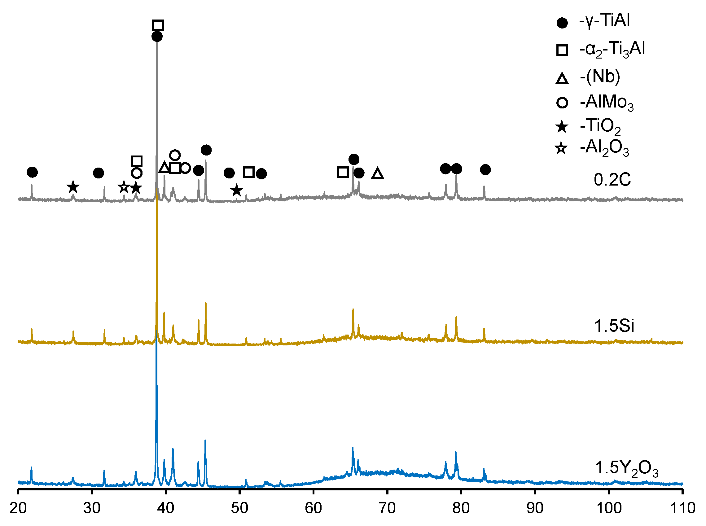
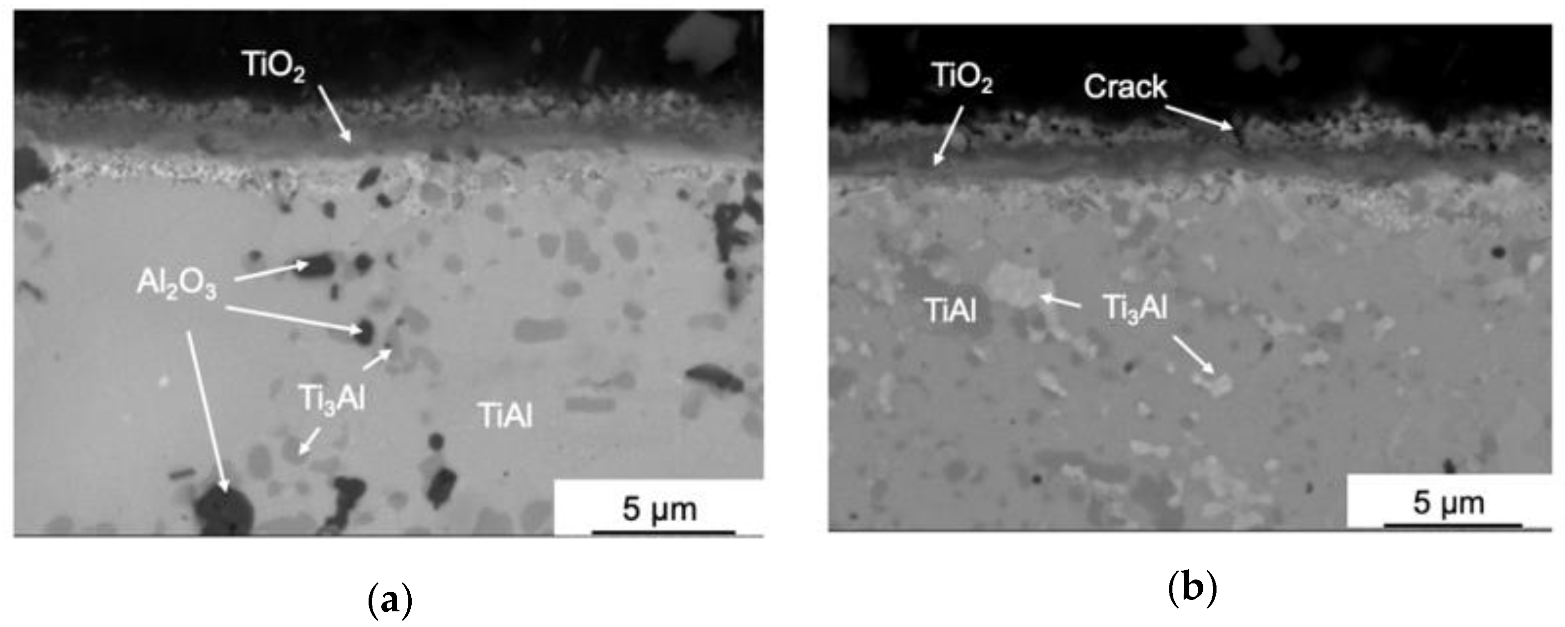
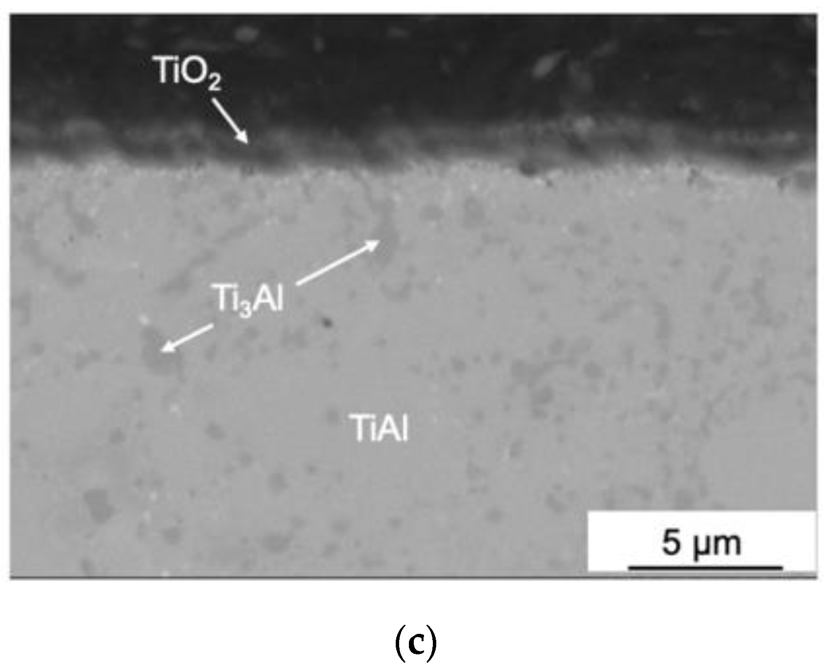
  • All of the alloys exhibited a high oxidation resistance at 800 °C. The oxidation kinetics can be described by a power–law with a power–law exponent of 5.461–5.580. A coating based on rutile TiO2 (~2 µm thick) was formed on the surface;
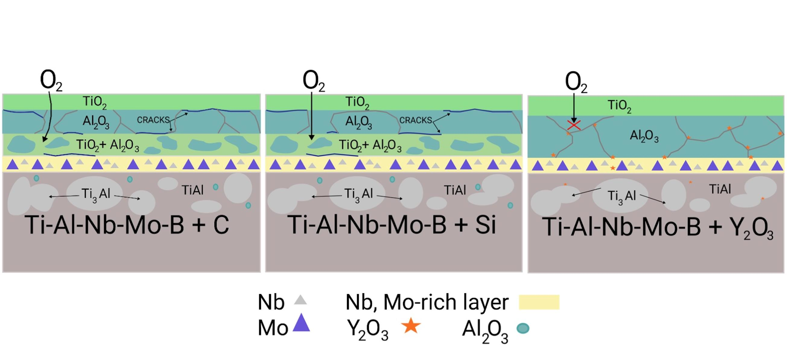
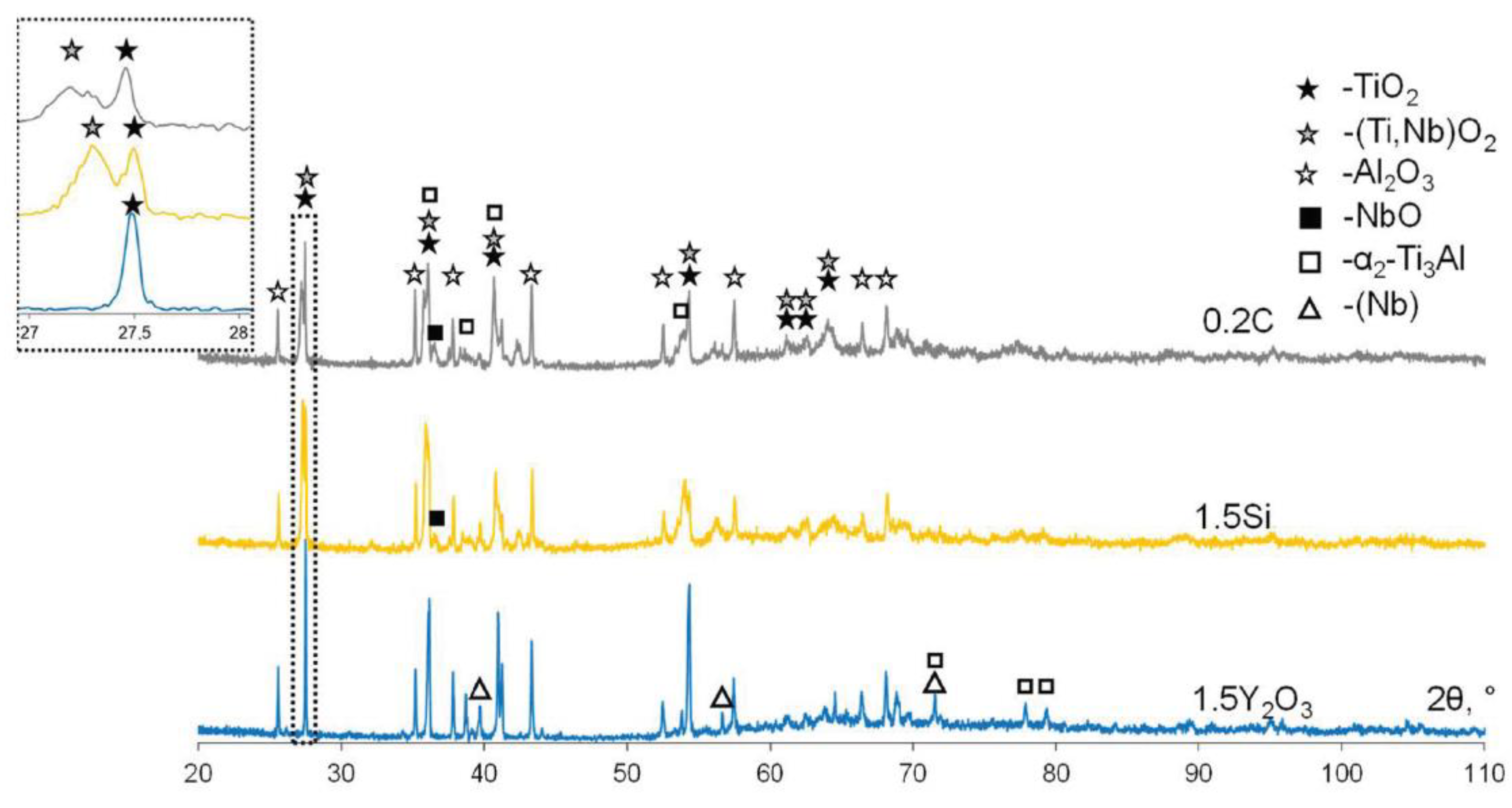
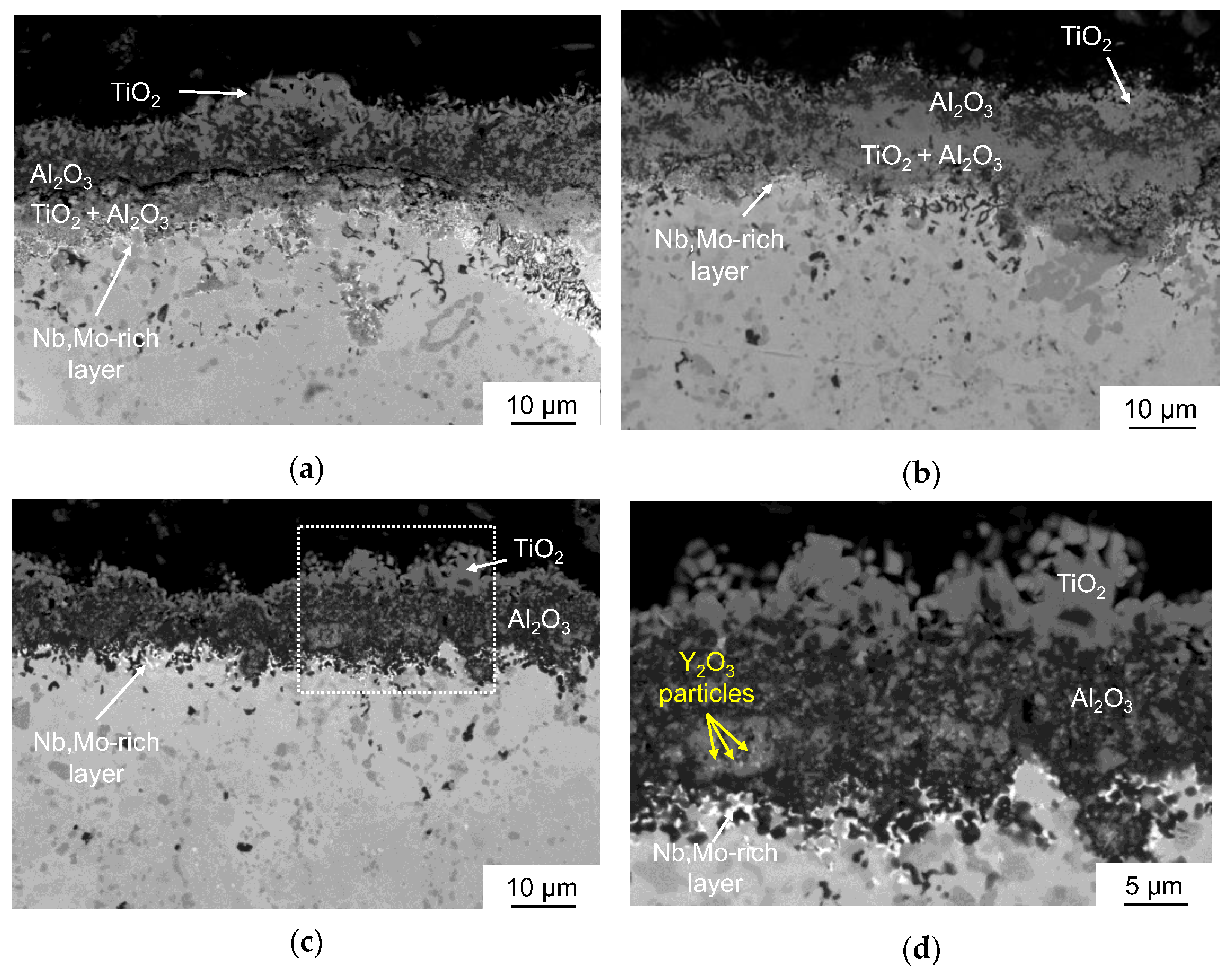
  • Oxidation of the 0.2C and 1.5Si alloys at 1100 °C caused the formation of three-layer TiO2/Al2O3/(TiO2 + Al2O3) coatings with a porous structure and a large number of cracks, resulting in spallation;
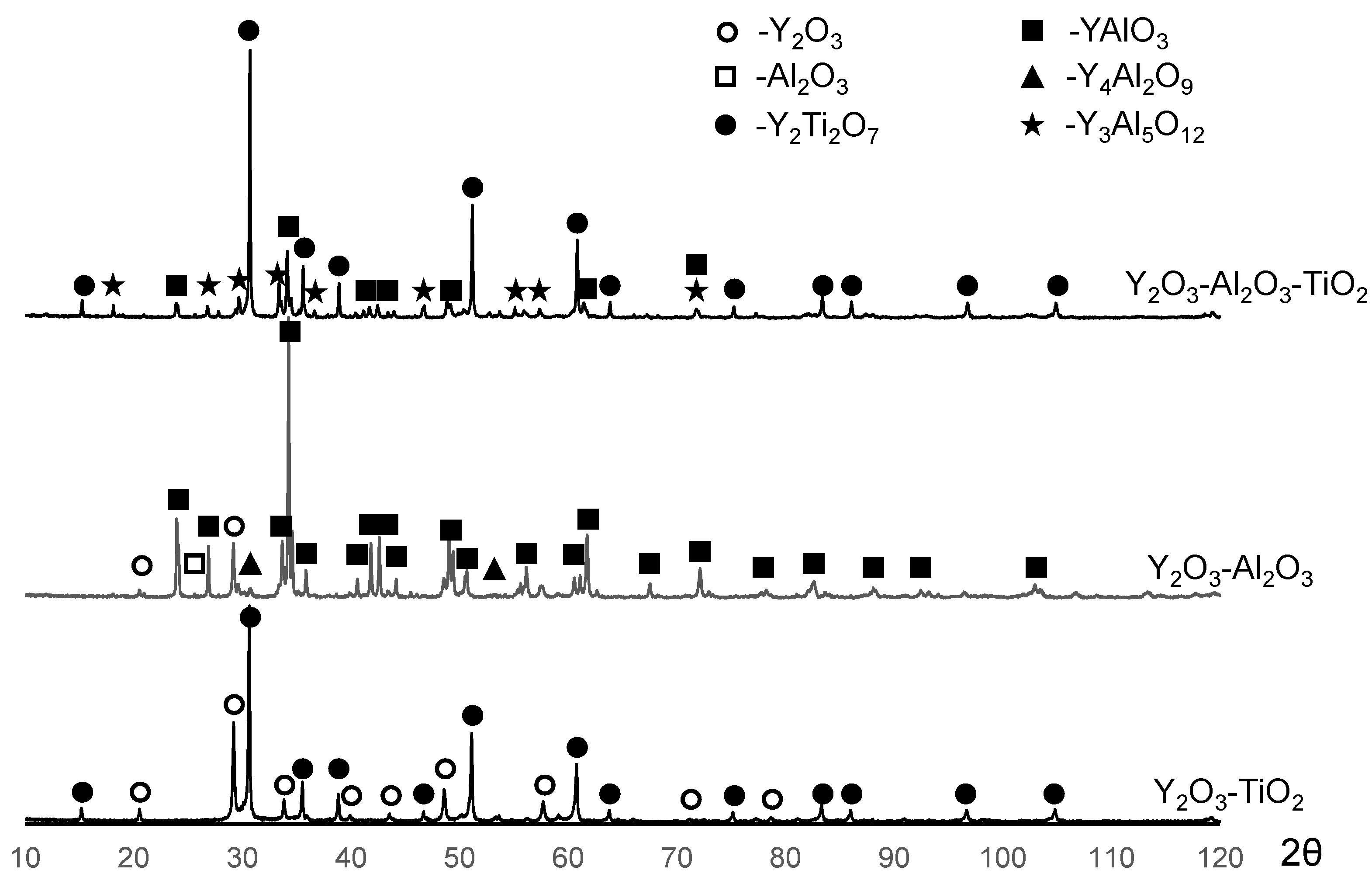
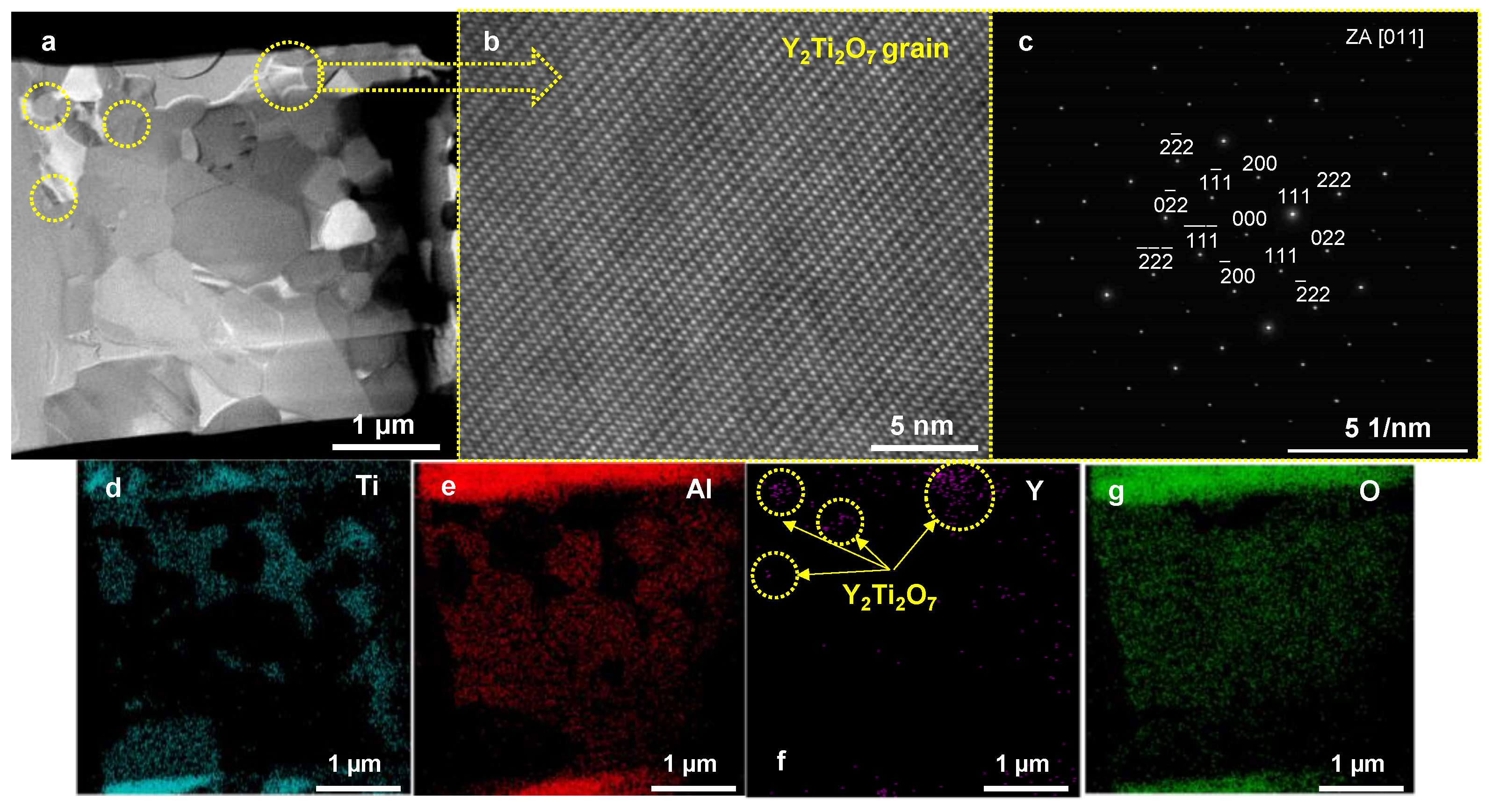
  • The alloy modified with 1.5Y2O3 had the best oxidation resistance at 1100 °C. During annealing, the oxide layer formed the Y2Ti2O7 phase, which has low oxygen permeability and high temperature stability. The formation of Y2Ti2O7 was accompanied by a decrease in the concentration of undesirable TiO2 oxide;
  • An interlayer rich in niobium and molybdenum was formed at the oxide layer/matrix interface. This interlayer ensures thermal stability of the alloy by preventing oxygen diffusion into the material bulk as well as titanium and aluminum diffusion toward the surface.

Author Contributions

Conceptualization, P.A.L. and G.M.M.; Formal analysis, P.A.L., G.M.M. and N.V.S.; Funding acquisition, E.A.L.; Investigation, P.A.L., G.M.M. and G.V.S.; Methodology, P.A.L. and G.M.M.; Resources, E.A.L.; Supervision, E.A.L.; Visualization, N.V.S.; Writing—original draft, P.A.L. and G.M.M.; Writing—review & editing, E.A.L. All authors have read and agreed to the published version of the manuscript.

Funding

This work was carried out with financial support from the Ministry of Education and Science of the Russian Federation (project no. 0718-2020-0034 of State Assignment).

Institutional Review Board Statement

Not applicable.

Informed Consent Statement

Not applicable.

Data Availability Statement

Not applicable.

Acknowledgments

This work was carried out with financial support from the Ministry of Education and Science of the Russian Federation (project no. 0718-2020-0034 of State Assignment).

Conflicts of Interest

The authors declare no conflict of interest.

References

  1. Gupta, R.K.; Pant, B. Titanium aluminides. Intermet. Matrix Compos. 2018, 4, 71–93. [Google Scholar] [CrossRef]
  2. Appel, F.; Brossmann, U.; Christoph, U.; Eggert, S.; Janschek, P.; Lorenz, U.; Mullauer, J.; Oehring, M.; Paul, J.D.H. Recent progress in the development of gamma titanium aluminide alloys. Adv. Eng. Mater. 2000, 2, 699–720. [Google Scholar] [CrossRef]
  3. Shi, J.; Zheng, A.; Lin, Z.; Chen, R.; Zheng, J.; Cao, Z. Effect of process control agent on alloying and mechanical behavior of L21 phase Ni–Ti–Al alloys. Mater. Sci. Eng. A 2019, 740–741, 130–136. [Google Scholar] [CrossRef]
  4. Nepapushev, A.A.; Moskovskikh, D.O.; Buinevich, V.S.; Vadchenko, S.G.; Rogachev, A.S. Production of Rounded Reactive Composite Ti/Al Powders for Selective Laser Melting by High-Energy Ball Milling. Met. Mater. Trans. B 2019, 50, 1241–1247. [Google Scholar] [CrossRef]
  5. Kenel, C.; Lis, A.; Dawson, K.; Stiefel, M.; Pecnik, C.; Barras, J.; Colella, A.; Hauser, C.; Tatlock, G.; Leinenbach, C.; et al. Mechanical performance and oxidation resistance of an ODS γ-TiAl alloy processed by spark plasma sintering and laser additive manufacturing. Intermetallics 2017, 91, 169–180. [Google Scholar] [CrossRef]
  6. Meng, K.; Guo, K.; Yu, Q.; Miao, D.; Yao, C.; Wang, Q.; Wang, T. Effect of annealing temperature on the microstructure and corrosion behavior of Ti-6Al-3Nb-2Zr-1Mo alloy in hydrochloric acid solution. Corros. Sci. 2021, 183, 109320. [Google Scholar] [CrossRef]
  7. Huang, Z.; Lin, J.; Sun, H. Microstructural changes and mechanical behaviour of a near lamellar γ-TiAl alloy during long-term exposure at 700 °C. Intermetallics 2017, 85, 59–68. [Google Scholar] [CrossRef]
  8. Galetz, M.; Ulrich, A.; Oskay, C.; Fähsing, D.; Laska, N.; Schulz, U.; Schütze, M. Oxidation-induced microstructural changes of the TiAl TNM-B1 alloy after exposure at 900 °C in air. Intermetallics 2020, 123, 106830. [Google Scholar] [CrossRef]
  9. Zhang, S.Z.; Zhang, C.J.; Du, Z.X.; Hou, Z.; Lin, P.; Kong, F.T.; Chen, Y.Y. Deformation behavior of high Nb containing TiAl based alloy in α + γ two phase field region. Mater. Des. 2016, 90, 225–229. [Google Scholar] [CrossRef]
  10. Niu, H.Z.; Chen, X.J.; Chen, Y.F.; Zhao, S.; Liu, G.H.; Zhang, D.L. Microstructural stability, phase transformation and mechanical properties of a fully-lamellar microstructure of a Mo-modified high-Nb γ-TiAl alloy. Mater. Sci. Eng. A 2020, 784, 139313. [Google Scholar] [CrossRef]
  11. Bizot, Q.; Politano, O.; Nepapushev, A.A.; Vadchenko, S.G.; Rogachev, A.S.; Baras, F. Reactivity of the Ti–Al system: Experimental study and molecular dynamics simulations. J. Appl. Phys. 2020, 127, 145304. [Google Scholar] [CrossRef]
  12. Ismaeel, A.; Wang, C.-S. Effect of Nb additions on microstructure and properties of γ-TiAl based alloys fabricated by selective laser melting. Trans. Nonferrous Met. Soc. China 2019, 29, 1007–1016. [Google Scholar] [CrossRef]
  13. Zhang, S.; Song, Z.; Han, J.; Zhang, C.; Lin, P.; Zhu, D.; Kong, F.; Chen, Y. Effect of 2–6 at.% Mo addition on microstructural evolution of Ti-44Al alloy. J. Mater. Sci. Technol. 2018, 34, 1196–1204. [Google Scholar] [CrossRef]
  14. Dahar, M.S.; Tamirisakandala, S.A.; Lewandowski, J.J. Fatigue crack growth and fracture behavior of as-cast Ti-43.5Al-4Nb-1Mo-0.1B (TNM) compared to Ti-48Al-2Nb-2Cr (4822). Intermetallics 2017, 91, 158–168. [Google Scholar] [CrossRef]
  15. Bernal, D.; Chamorro, X.; Hurtado, I.; Madariaga, I. Evolution of lamellar microstructures in a cast TNM alloy modified with boron through single-step heat treatments. Intermetallics 2020, 124, 106842. [Google Scholar] [CrossRef]
  16. Imayev, V.; Gaisin, R.; Rudskoy, A.; Nazarova, T.; Shaimardanov, R.; Imayev, R. Extraordinary superplastic properties of hot worked Ti–45Al–8Nb–0.2C alloy. J. Alloy Compd. 2016, 663, 217–224. [Google Scholar] [CrossRef]
  17. Huang, Z.W. Thermal stability of Ti–44Al–4Nb–4Zr–0.2Si–1B alloy. Intermetallics 2013, 42, 170–179. [Google Scholar] [CrossRef]
  18. Dahar, M.S.; Tamirisakandala, S.A.; Lewandowski, J.J. Evolution of fatigue crack growth and fracture behavior in gamma titanium aluminide Ti-43.5Al-4Nb-1Mo-0.1B (TNM) forgings. Int. J. Fatigue 2018, 111, 54–69. [Google Scholar] [CrossRef]
  19. Singh, V.; Mondal, C.; Sarkar, R.; Bhattacharjee, P.P.; Ghosal, P. Dynamic recrystallization of a β(B2)-Stabilized γ-TiAl based Ti–45Al–8Nb–2Cr-0.2B alloy: The contributions of constituent phases and Zener-Hollomon parameter modulated recrystallization mechanisms. J. Alloys Compd. 2020, 828, 154386. [Google Scholar] [CrossRef]
  20. Narayana, P.L.; Kim, J.H.; Yun, D.W.; Kim, S.E.; Reddy, N.S.; Yeom, J.T.; Seo, D.; Hong, J.K. High temperature isothermal oxidation behavior of electron beam melted multi-phase γ-TiAl alloy. Intermetallics 2022, 141, 107424. [Google Scholar] [CrossRef]
  21. Gong, X.; Chen, R.R.; Fang, H.Z.; Ding, H.S.; Guo, J.J.; Su, Y.; Fu, H.Z. Synergistic effect of B and Y on the isothermal oxidation behavior of TiAl-Nb-Cr-V alloy. Corros. Sci. 2017, 131, 376–385. [Google Scholar] [CrossRef]
  22. Wang, Q.; Chen, R.; Yang, Y.; Guo, J.; Su, Y.; Ding, H.; Fu, H. Effects of V and B, Y additions on the microstructure and creep behaviour of high-Nb TiAl alloys. J. Alloy Compd. 2018, 747, 640–647. [Google Scholar] [CrossRef]
  23. Shida, Y.; Anada, H. The influence of ternary element addition on the oxidation behaviour of TiAl intermetallic compound in high temperature air. Corros. Sci. 1993, 35, 945–953. [Google Scholar] [CrossRef]
  24. Yan, K.; Guo, H.B.; Gong, S.K. High-temperature oxidation behavior of β-NiAl with various reactive element dopants in dry and humid atmospheres. Corros. Sci. 2014, 83, 335–342. [Google Scholar] [CrossRef]
  25. Klein, L.; Shen, Y.; Killian, M.S.; Virtanen, S. Effect of B and Cr on the high temperature oxidation behaviour of novel γ/γ′-strengthened Co-base superalloys. Corros. Sci. 2011, 53, 2713–2720. [Google Scholar] [CrossRef]
  26. Yao, T.; Liu, Y.; Liu, B.; Song, M.; Zhao, K.; Zhang, W.; He, Y. Influence of carburization on oxidation behavior of High Nb contained TiAl alloy. Surf. Coat. Technol. 2015, 277, 210–215. [Google Scholar] [CrossRef]
  27. Liu, C.; Wang, Y.; Han, W.; Ma, T.; Ma, D.; Zhang, Y. Achieving Superior High-Temperature Strength and Oxidation Resistance of TiAl Nanocomposite through In Situ Semicoherent MAX Phase Precipitation. ACS Appl. Mater. Interfaces 2022, 14, 8394–8403. [Google Scholar] [CrossRef]
  28. Ma, T.; Li, Q.; Wang, Y.; Wang, X.; Dong, D.; Zhu, D. Microstructure and mechanical properties of micro-nano Ti2AlC-reinforced TiAl composites. Intermetallics 2022, 146, 107563. [Google Scholar] [CrossRef]
  29. Lim, H.P.; Liew, W.Y.; Melvin, G.J.H.; Jiang, Z.-T. A Short Review on the Phase Structures, Oxidation Kinetics, and Mechanical Properties of Complex Ti-Al Alloys. Materials 2021, 14, 1677. [Google Scholar] [CrossRef]
  30. Crespo-Villegas, J.; Cavarroc, M.; Knittel, S.; Martinu, L.; Klemberg-Sapieha, J.E. Protective TixSiy coatings for enhanced oxidation resistance of the ɣ-TiAl alloy at 900 °C. Surf. Coat. Technol. 2021, 430, 127963. [Google Scholar] [CrossRef]
  31. Bauer, P.-P.; Swadźba, R.; Klamann, L.; Laska, N. Aluminum diffusion inhibiting properties of Ti5Si3 at 900 °C and its beneficial properties on Al-rich oxidation protective coatings on γ-TiAl. Corros. Sci. 2022, 201, 110265. [Google Scholar] [CrossRef]
  32. Zhang, K.; Xin, L.; Ma, T.; Chang, H.; Lu, Y.; Feng, C.; Zhu, S.; Wang, F. Investigation of the role of silicon in TiAlSiN coating deposited on TiAl alloys during long-term oxidation. Corros. Sci. 2022, 204, 110394. [Google Scholar] [CrossRef]
  33. Zhang, K.; Xin, L.; Lu, Y.; Cheng, Y.; Wang, X.; Zhu, S.; Wang, F. Improving oxidation resistance of γ-TiAl based alloy by depositing TiAlSiN coating: Effects of silicon. Corros. Sci. 2021, 179, 109151. [Google Scholar] [CrossRef]
  34. Wang, Q.; Wu, W.-Y.; Jiang, M.-Y.; Cao, F.-H.; Wu, H.-X.; Sun, D.-B.; Yu, H.-Y.; Wu, L.-K. Improved oxidation performance of TiAl alloy by a novel Al–Si composite coating. Surf. Coat. Technol. 2020, 381, 125126. [Google Scholar] [CrossRef]
  35. Bobzin, K.; Brögelmann, T.; Kalscheuer, C.; Liang, T. Al-Si and Al-Si-Y coatings deposited by HS-PVD for the oxidation protection of γ-TiAl. Surf. Coat. Technol. 2018, 350, 587–595. [Google Scholar] [CrossRef]
  36. Swadźba, R.; Mendala, B.; Bauer, P.-P.; Laska, N.; Schulz, U. Microstructure and cyclic oxidation resistance of Si-aluminide coatings on γ-TiAl at 850 °C. Surf. Coat. Technol. 2020, 403, 126361. [Google Scholar] [CrossRef]
  37. Wu, Y.; Hagihara, K.; Umakoshi, Y. Improvement of cyclic oxidation resistance of Y-containing TiAl-based alloys with equiaxial gamma microstructures. Intermetallics 2005, 13, 879–884. [Google Scholar] [CrossRef]
  38. Xiang, L.; Zhao, L.; Wang, Y.; Zhang, L.; Lin, J. Synergistic effect of Y and Nb on the high temperature oxidation resistance of high Nb containing TiAl alloys. Intermetallics 2012, 27, 6–13. [Google Scholar] [CrossRef]
  39. Loginov, P.A.; Kaplanskii, Y.Y.; Markov, G.M.; Patsera, E.I.; Vorotilo, K.V.; Korotitskiy, A.V.; Shvyndina, N.V.; Levashov, E.A. Structural and mechanical properties of Ti–Al–Nb–Mo–B alloy produced from the SHS powder subjected to high-energy ball milling. Mater. Sci. Eng. A 2021, 814, 141153. [Google Scholar] [CrossRef]
  40. Lu, W.; Chen, C.L.; He, L.L.; Wang, F.H.; Lin, J.P.; Chen, G.L. (S)TEM study of different stages of Ti–45Al–8Nb–0.2W–0.2B–0.02Y alloy oxidation at 900 °C. Corros. Sci. 2008, 50, 978–988. [Google Scholar] [CrossRef]
  41. Lin, J.P.; Zhao, L.L.; Li, G.Y.; Zhang, L.Q.; Song, X.P.; Ye, F.; Chen, G.L. Effect of Nb on oxidation behavior of high Nb containing TiAl alloys. Intermetallics 2011, 19, 131–136. [Google Scholar] [CrossRef]
  42. Maurice, V.; Despert, G.; Zanna, S.; Josso, P.; Bacos, M.-P.; Marcus, P. XPS study of the initial stages of oxidation of α2-Ti3Al and γ-TiAl intermetallic alloys. Acta Mater. 2007, 55, 3315–3325. [Google Scholar] [CrossRef]
  43. Li, X.T.; Huang, L.J.; Jiang, S.; Gao, Y.N.; An, Q.; Wang, S.; Zhang, R.; Geng, L. Microstructure and super oxidation resistance of the network structured Ti-Al-Si coating. J. Alloy Compd. 2019, 807, 151679. [Google Scholar] [CrossRef]
  44. Tanaka, M.; Matsudaira, T.; Kawai, E.; Kawashima, N.; Matsumoto, U.; Ogawa, T.; Takeuchi, M.; Kitaoka, S. Effect of chemical composition on mass transfer in Y2Ti2O7 under oxygen potential gradient at high temperatures. J. Ceram. Soc. Jpn. 2021, 129, 22–31. [Google Scholar] [CrossRef]
  45. D’Isanto, F.; Smeacetto, F.; Martin, H.-P.; Sedlák, R.; Lisnichuk, M.; Chrysanthou, A.; Salvo, M. Development and characterisation of a Y2Ti2O7-based glass-ceramic as a potential oxidation protective coating for titanium suboxide (TiOx). Ceram. Int. 2021, 47, 19774–19783. [Google Scholar] [CrossRef]
  46. Liu, T.; Wang, L.; Wang, C.; Shen, H. Effect of Al content on the oxidation behavior of Y2Ti2O7-dispersed Fe-14Cr ferritic alloys. Corros. Sci. 2016, 104, 17–25. [Google Scholar] [CrossRef]
  47. Nguyen, S.T.; Nakayama, T.; Suematsu, H.; Suzuki, T.; Takeda, M.; Niihara, K. Low thermal conductivity Y2Ti2O7 as a candidate material for thermal/environmental barrier coatings. Ceram. Int. 2016, 42, 11314–11323. [Google Scholar] [CrossRef]
  48. Tanaka, M.; Kitaoka, S.; Yoshida, M.; Sakurada, O.; Hasegawa, M.; Nishioka, K.; Kagawa, Y. Structural stabilization of EBC with thermal energy reflection at high temperatures. J. Eur. Ceram. Soc. 2017, 37, 4155–4161. [Google Scholar] [CrossRef]
  49. Su, Y.J.; Trice, R.W.; Faber, K.T.; Wang, H.; Porter, W.D. Thermal Conductivity, Phase Stability, and Oxidation Resistance of Y3Al5O12 (YAG)/Y2O3–ZrO2 (YSZ) Thermal-Barrier Coatings. Oxid. Met. 2004, 61, 253–271. [Google Scholar] [CrossRef]
Figure 1. A schematic illustration of the equipment for the oxidation test.
Ceramics 05 00030 g001
Figure 2. The SEM images of the as-HIPed alloys: 0.2C (a), 1.5Si (b), and 1.5Y2O3 (c).
Ceramics 05 00030 g002aCeramics 05 00030 g002b
Figure 3. The XRD patterns of the as-HIP-ed alloys 0.2C, 1.5Si, and 1.5Y2O3.
Ceramics 05 00030 g003
Figure 4. The oxidation kinetic curves after isothermal annealing at 800 °C.
Ceramics 05 00030 g004
Figure 5. The XRD patterns of the 0.2C, 1.5Si, and 1.5Y2O3 alloys’ oxidized layers after annealing at 800 °C.
Ceramics 05 00030 g005
Figure 6. A cross-sectional oxidized layer image of the alloys 0.2C (a), 1.5Si (b), and 1.5Y2O3 (c) after isothermal annealing at 800 °C.
Ceramics 05 00030 g006aCeramics 05 00030 g006b
Figure 7. The sample images after annealing at 1100 °C.
Ceramics 05 00030 g007
Figure 8. The oxidation kinetic curves after isothermal annealing at 1100 °C.
Ceramics 05 00030 g008
Figure 9. The XRD patterns of the oxidized layers of 0.2C, 1.5Si, and 1.5Y2O3 alloys after annealing at 1100 °C.
Ceramics 05 00030 g009
Figure 10. The cross-sectional oxidized layer image of alloys 0.2C (a), 1.5Si (b), and 1.5Y2O3 (c) after isothermal annealing at 1100 °C and a magnified image of the area highlighted by a white dotted line (d).
Ceramics 05 00030 g010
Figure 11. The STEM image of a lamella cut from the oxide layer of a 1.5Y2O3 sample (a), HRTEM image of a Y2Ti2O7 particle (b), and electron diffraction from this grain (c); EDS elemental maps of titanium (d), aluminum (e), yttrium (f), and oxygen (g).
Ceramics 05 00030 g011
Figure 12. The X-ray patterns of the Y2O3–TiO2, Y2O3–Al2O3, and Y2O3–Al2O3–TiO2 powder mixtures sintered at 1100 °C.
Ceramics 05 00030 g012
Table 1. The phase composition of the HIP-ed alloys 0.2C, 1.5Si, and 1.5Y2O3.
SamplePhase Concentration, wt. %
γ-TiAl
P4/mmm
α2-Ti3Al
P63/mmc
(Nb)
Im-3m
AlMo3
Pm-3n
0.2C781732
1.5Si801532
1.5Y2O3801721
Table 2. The oxidation kinetics characteristics of the 0.2C, 1.5Si, and 1.5Y2O alloys at 800 °C and the values of the oxide layer thickness (h) after 30 h of isothermal holding.
AlloyΔM, µg/cm2knh, µm
0.2C3.9136854982.06
1.5Si4.187.555802.28
1.5Y2O33.5144654611.89
Table 3. The phase composition of the 0.2C, 1.5Si, and 1.5Y2O3 alloys after oxidation annealing at 800 °C.
SamplePhase Concentration, wt. %
γ-TiAl
P4/mmm
α2-Ti3Al
P63/mmc
(Nb)
Im-3m
AlMo3
Pm-3n
TiO2
P42/mnm
Al2O3
P63mc
0.2C7483294
1.5Si7683274
1.5Y2O377631103
Table 4. The oxidation kinetics characteristics of the 0.2C, 1.5Si, and 1.5Y2O alloys at 1100 °C and the values of the oxide layer thickness (h) after 30 h of isothermal holding.
AlloyΔM, ug/cm2knh, µm
0.2C61191127042086
1.5Si37886229211744
1.5Y2O317 56411342
Table 5. The phase composition of the 0.2C, 1.5Si, and 1.5Y2O3 alloys after oxidation annealing at 1100 °C.
SamplePhase Concentration, wt. %
TiO2
P42/mnm
(Ti,Nb)O2
P42/mnm
Al2O3
P63mc
(Nb)
Im-3m
α2-Ti3Al
P63/mmc
NbO
Pm-3n
0.2C251752262
1.5Si271942372
1.5Y2O338-51110-
Table 6. The phase composition of the Y2O3–TiO2, Y2O3–Al2O3, and Y2O3–Al2O3–TiO2 powder mixtures sintered at 1100 °C.
SamplePhase Concentration, wt. %
Y2O3
Ia-3
Al2O3
R-3c
Y2Ti2O7
Fd-3m
YAlO3
Pbnm
Y4Al2O9
P21/c
Y3Al5O12
Ia-3d
Y2O3–TiO225-75---
Y2O3–Al2O365-8011-
Y2O3–Al2O3–TiO2--7010-20
Publisher’s Note: MDPI stays neutral with regard to jurisdictional claims in published maps and institutional affiliations.

