Article

Hydrothermal Synthesis, Characterization, and Sintering Behavior of Core-Shell Particles: A Principle Study on Lanthanum Strontium Cobaltite Coated with Nanosized Gadolinium Doped Ceria

1
Department of Energy Conversion and Storage, Technical University of Denmark (Risø Campus), Frederiksborgvej 399, 4000 Roskilde, Denmark
2
State Key Laboratory of Advanced Welding and Joining, Harbin Institute of Technology, Harbin 150001, China
3
Institut für Anorganische Chemie, Christian-Albrechts-Universität zu Kiel, Max-Eyth-Straße 2, D-24118 Kiel, Germany
*
Author to whom correspondence should be addressed.
Ceramics 2018, 1(2), 246-260; https://doi.org/10.3390/ceramics1020020
Submission received: 29 August 2018 / Revised: 21 September 2018 / Accepted: 28 September 2018 / Published: 2 October 2018
(This article belongs to the Special Issue Functional Ceramics for Energy Applications)

Abstract

:
In this work, nanostructured (La0.6Sr0.4)0.99CoO3 (LSC)-Ce0.8Gd0.2O1.9 (CGO) core-shell particles were prepared by precipitating CGO nanoparticles on the surface of LSC particles under hydrothermal conditions. The as-prepared core-shell particles were sintered by spark plasma sintering (SPS) and conventional sintering, and the microstructure evolution and densification behavior were studied. Dense microstructures were reached using both sintering methods at relatively low temperatures. In the case of SPS, the core-shell architecture was partially maintained and nano-structured CGO grains were formed, while conventional sintering led to the formation of larger CGO grains. This work covers a detailed characterization of (a) the individual LSC-CGO core-shell particles and (b) the composites after densification.

Graphical Abstract

1. Introduction

The search for new functional materials in numerous fields of applications has led to the development of advanced composite materials combining the distinctive behavior of each constituent to obtain tailored properties. Such composite architectures can be controlled down to the nanoscale; in particular, the core-shell morphology has been used to combine properties of each component in functional materials such as photonic crystals, biomedical compatible systems, catalysts and magnetic structures [1,2,3].
Composites based on La0.6Sr0.4CoO3 (LSC) and Ce0.8Gd0.2O1.9 (CGO) are widely used as oxygen electrodes in solid oxide fuel/electrolysis cells (SOFC/SOECs) and are considered in oxygen transport membranes (OTMs) [4,5,6]. Especially for OTMs, a dense (dual-phase) composite membrane consisting of LSC and CGO is of interest because a combination of materials with a high electronic conductivity (LSC) and a high ionic conductivity (CGO) can lead to a high performance in terms of the oxygen production. However, obtaining such desired structures in a dense bulk form is challenging due to the fact that the sintering temperatures for these two materials are different and that the high temperature required for densifying a CGO of poor sinterability (1400–1600 °C to reach the full density of pure CGO) is problematic [7,8]. Moreover, since LSC and CGO have rather different thermal expansion coefficients, it is even more difficult to obtain a fully dense large sample without cracking [9]. Ideally, for OTM applications, the microstructure after sintering should consist of small, but still percolating, grain networks in order to maintain both the ionic and electronic percolations. Therefore, it requires fine control on the phase volume fractions and phase arrangement in the primary powders. Such a microstructure is difficult to obtain with conventional sintering, at high temperatures, due to the severe structural rearrangements [10,11].
One possible way to realize a controlled and designed microstructure in a densified composite is to use core-shell nanostructures with a pre-arranged architecture as building blocks for bottom-up manufacturing of functional nanocomposite ceramics. Recent examples realizing this concept include the use of PbTe-PbS core-shell particles as building blocks for highly homogeneous thermoelectrics [12], ceramics with excellent dielectric properties made from core-shell structured SiO2-TiO2 particles synthesized using a solvothermal route [13], and the application of SrTiO3-NiFe2O4 core-shell particles prepared using a combination of sol-gel and co-precipitation methods to obtain structured ceramics [14].
However, the densification of the core-shell particles to a ceramic without destroying the original structure by using the conventional sintering is challenging because of the inherent severe structural rearrangement. Even designed core-shell structures do not necessarily lead to core-shell ceramic composites, due to a lattice mismatch, a sinterability difference, interfacial diffusions and/or phase reactions. An interesting alternative to the conventional sintering is spark plasma sintering (SPS), which combines a pulsed direct electric current and uniaxial pressure for the consolidation of powders. Thanks to the very fast densification process as a result of the Joule heating, the applied pressure and the presence of an electric field, SPS can sinter powders to a high density at a lower temperature and in a shorter time than that in a conventional sintering process [15,16]. Examples, where the use of SPS leads to a micro-graded structure, have been reported for sintering BaTiO3-SrTiO3 and BaTiO3-BaZrO3 core-shell particles [17] and for producing ZrO2-ZrB2 nano-ceramics [18].
Using LSC-CGO core-shell particles as starting materials with a designed pre-arrangement of the two phases and accomplishing sintering at a low temperature (1000 °C), using SPS are demonstrated in this work. Here, the hydrothermal synthesis and detailed characterization (by X-ray diffraction, transmission electron microscopy and scanning transmission electron microscopy coupled with energy-dispersive X-ray spectroscopy) of the core-shell LSC-CGO particles are described. In addition, the influence of SPS and conventional sintering on microstructure evolution of the as-prepared LSC-CGO core-shell particles are compared. Furthermore, the SPS-densified LSC-CGO composite was investigated in a thermal cycling process in air.

2. Experimental

2.1. Preparation of LSC-CGO Core-Shell Particles in a Hydrothermal Autoclave

Commercial (La0.6Sr0.4)0.99CoO3 powder (Kusaka Rare Metal Products Co. Ltd., Tokyo, Japan), Ce(NO3)3•6H2O, Gd(NO3)3•6H2O salts (Sigma Aldrich, St. Louis, MO, USA, ≥ 99%) and NaOH (Sigma Aldrich, ≥ 98%) were used for the synthesis as purchased. The particle size of the LSC was measured using an LS 13 320 Laser Diffraction Particle Size Analyzer (using the universal liquid module, measured in the range of 0.04 µm to 2000 µm) that displayed a bimodal distribution centered on ~0.3 µm and ~1.0 µm respectively (Figure S1 in the supplementary material). For a molar ratio of n[LSC core]:n[CGO shell] = 4:1 in the core-shell particles, the molar ratio of Ce(NO3)3•6H2O:Gd(NO3)3•6H2O:NaOH:LSC was kept at 0.44:0.11:4.50:2.20.LSC powders (0.5 g) were first dispersed in deionized H2O by an ultrasonic treatment for 20 min, then 0.19 g Ce(NO3)3•6H2O and 0.05 g Gd(NO3)3•6H2O salts were added into the slurry, followed by adding dropwise 4.5 mL 1 mol L−1 NaOH aqueous solution. The whole slurry was then transferred into a Teflon liner (230 mL in capacity) and the overall volume was fixed to 45 mL by adding DI H2O. Afterwards, the Teflon liner was sealed in a stainless steel autoclave, which was heated to 100 °C using a hot plate with a magnetic stirrer. A magnetic bar was stirring inside the slurry in order to reduce the sedimentation and agglomeration of LSC powders. The synthesis was conducted at 100 °C, for 24 h and then the slurry with particles was left to cool down. The particles were filtered, washed and air-dried for later processing.

2.2. Densification of LSC-CGO Particles

2.2.1. Spark Plasma Sintering (SPS)

The SPS system (DR. Sinter Lab 515S, Fuji Electronic Industrial Co., Ltd., Saitama, Japan) was used, with a pulsed direct current regulated by on-off settings. The as-prepared LSC-CGO particles were filled into a Ø16 mm graphite die, which was then pressed under a small pressure of around 5 MPa to ensure a good contact between the powder and graphite punches. In an SPS process, a pulsed electric current was then passed through the powders under a vacuum of about 10−5 atm. The heating rate was 100 °C min−1. In order to remove all gases from the powders, after the temperature reached 800 °C, a uniaxial pressure was applied and it arrived at 50 MPa when the temperature reached 900 °C. The sintering temperature was held at 1000 °C with a constant uniaxial pressure of 50 MPa for 6 min. The cooling rate was set at 100 °C min−1 from 1000 to 500 °C to avoid cracking. During the sintering process, all parameters such as the electric current, the temperature, the uniaxial pressure, and the sample displacement (shrinkage) were recorded and they are presented in Figure S2 in the supplementary material. Sintering at lower temperatures (<1000 °C) was not successful as samples obtained in these experiments were too fragile to be handled.

2.2.2. Conventional Sintering in a Muffle Furnace in Air

LSC-CGO particles with an amount of 1 g were die-pressed into a pellet at 1000 kg load and then isostatically pressed at 65,000 kg load. Afterwards, the pellet was sintered inside a muffle furnace in air at 1250 °C for 6 h. The heating rate was set to 100 °C h−1. Before the temperature reached 1250 °C, the pellet was kept at 800 °C for 2 h. The cooling rate was also set at 100 °C h−1. The temperature profile of the furnace is presented in Figure S3 in the supplementary material.

2.3. Investigation of the SPS-Densified LSC-CGO Composite in a Thermal Cycling Process in Air

The SPS-densified LSC-CGO sample was heat treated in air in a furnace at 700 °C for 1 h. The temperature ramp for both the heating and cooling processes was 20 °C h−1.

2.4. Characterization

For comparison, the raw as-bought LSC particles and the as-prepared LSC-CGO core-shell particles were separately characterized by powder XRD performed on a Bruker D8 Advance diffractometer (Cu Kα radiation) with 2θ = 20–90° at a step size of 0.01° s−1. The diffraction patterns were compared with standard patterns collected in the ICDD PDF2 database using the Diffrac. Eva Suite (Bruker) and were further refined using the Rietveld method using the FullProf Suite [19]. Details on the refinement and the refinement residuals are presented in the supplementary material (Tables S1 and S2).
Scanning electron microscopy (SEM) was carried out by using a Zeiss Merlin SEM equipped with a field emission gun. The sintered pellets and the heat-treated SPS-densified LSC-CGO sample were cut, embedded in epoxy, and then polished for SEM microstructure investigations. To assure representability, areas in the center of all samples were chosen for analysis. The samples were also broken for the microscopy observation on the fracture surface. All samples were coated with ~20 nm of carbon on the surface in order to increase the surface’s electrical conductivity. At each observed area, two images were recorded simultaneously by processing the signals from secondary electrons (SE2) and backscattered electrons (BSE) separately, collected using a high-efficiency secondary electron detector and an in column energy-selective backscattered electron detector. The software ThreshAlyzer was used to do image segmentation and to statistically quantify the grain sizes when possible. Details on the image analysis can be found in the supplementary material. For the compositional analysis, energy-dispersive X-ray spectroscopy (SEM-EDS) was carried out by using a Bruker EDS detector.
For the transmission electron microscopy (TEM) characterization, the LSC-CGO particles were dispersed in ethanol by means of ultrasonic treatment and were dropped onto a holey carbon film/Au grid. Bright field TEM (BF-TEM) images were recorded with a JEOL 3000F microscope operating at 300 kV with a field emission gun. Dark-field scanning transmission electron microscopy (DF-STEM) was carried out by using the JEOL 3000F equipped with a STEM unit and a high angle annular dark field (HAADF) detector. The nominal probe size was 0.5 nm and the camera length was 12 cm. For compositional analysis, energy-dispersive X-ray spectroscopy (STEM-EDS) was carried out by using an Oxford Instruments EDS detector. BF-TEM images were analyzed using the software Gatan DigitalMicrograph while the DF-STEM images, as well as EDS elemental analysis, were processed by using the software INCA.

3. Results and Discussion

3.1. Structure and Morphology of Nano-Structured LSC-CGO Core-Shell Particles

The phase purity and morphology of the commercial LSC powder as the starting material were analyzed first by XRD and SEM. The Rietveld refinement in Figure 1a shows a good match between the experimental pattern in both the intensity and Bragg positions and the calculated pattern based on the rhombohedral perovskite structure (space group: R-3c). As observed in the SEM image (Figure 1b), the LSC particles displayed sharp edges and smooth surfaces. The particle size was not homogeneous, as found by the laser diffraction measurement that the particles displayed a bimodal size distribution (0.04–0.45 µm and 0.6–1.83 µm). Figure 1c presents the refinement of the XRD pattern of the as-prepared LSC-CGO particles. Although weak, diffraction peaks (Bragg positions indexed by red vertical bars) corresponding to the newly formed CGO (cubic, space group: Fm-3m) were observed in addition to the diffraction peaks of the LSC powders. The significant broadening of the CGO diffraction peaks indicates that the CGO phase from the hydrothermal synthesis consisted of small particles relative to the LSC particles. SEM analysis (Figure 1d) shows that the LSC particles in the LSC-CGO sample generally kept the shape and size observed for the raw LSC powders. However, for the LSC-CGO sample, sharp edges were rarely observed. The surfaces of both large and small LSC particles became rough, which can be interpreted as a coverage of LSC particles with the new phase determined by XRD to be CGO.
For a more detailed analysis, the LSC-CGO particles were characterized by transmission electron microscopy and the results are summarized in Figure 2. A BF-TEM image, giving a two-dimensional projection of an LSC-CGO particle, is presented in Figure 2a. It is clear that the large particles were coated with nano-sized crystals. The insets of Figure 2a contain a fast Fourier transform (FFT) and a high-resolution image of the shell. The FFT shows ring patterns indicating that the shell consisted of many small, randomly oriented crystals. Determined by the radius, the rings were separately assigned to the three crystal planes (111), (200) and (220) of a CGO crystal. Details on the FFT conversion, measurement and assignment can be found in Figure S5 in the supplementary material. In the high-resolution TEM image, two sets of lattice spacings were observed in a single CGO nanoparticle. The measured interplanar spacings were 3.1 Å and 2.7 Å (the angle between them was 55°) and were consistent with the distances of the (111) and (200) planes of a CGO crystal respectively. The mean size of CGO particles was roughly estimated to be 6 ± 1 nm, by measuring 12 particles. However, it should be noted that the number of distinguishable particles was limited due to overlapping. Figure 2b shows a DF-STEM image of the LSC-CGO particles in which the rough surface is clearly revealed. STEM-EDS maps of all detected metal elements are shown in Figure 2c. X-ray photons emitted from La, Sr and Co were mostly detected in the inner core positions of the LSC-CGO particles. In comparison, the X-ray photons from Ce and Gd were observed over extended areas corresponding to whole areas of the LSC-CGO particles shown in the DF-STEM image. The elemental maps indicate that a core-shell particle was composed of an integral CGO shell covering an LSC core. In addition, a similar distribution of Ce and Gd indicates that Gd was doped into the lattice of CeO2, i.e., Gd-doped CeO2. Standardless quantification of the EDS data showed that the ratio of the atomic percent of Ce to that of Gd was 3.6, which is close to the molar ratio (n[Ce]/n[Gd] = 4/1) in the nominal composition of Ce0.8Gd0.2O1.9. To make it more illustrative, the DF-STEM image, La and Ce element maps are integrated together in Figure 2c, where it can be seen that a CGO shell (represented by Ce) covered an LSC core (represented by La) forming an LSC-CGO core-shell structure.
Under the applied hydrothermal condition, the formation of CGO crystals was expected to follow a normal hydrothermal synthesis route that involved the hydrolysis of Ce and Gd cations in the alkaline aqueous media and subsequent dehydration and crystallization to metal oxides under the heat treatment at 100 °C in the autoclave. For a hydrothermal system containing more than one metallic cation, it is necessary that the applied conditions should be favorable for the simultaneous hydrolysis and dehydration of all cations to a similar degree in order to obtain a mixed oxide of determined composition [20]. These conditions appear to have been realized as Ce and Gd were found to be homogeneously distributed (Figure 2c) and the measured composition of CGO was close to the nominal value. According to the classical nucleation theory, the free energy barrier for the homogeneous nucleation is higher than that for the heterogeneous nucleation [21,22]. The pre-suspended LSC particles in the autoclave worked as ‘impurities’ and provided ‘crystallization sites’ for the CGO phase. Therefore, the crystallization of CGO from the supersaturated solution under the increased temperature might prefer to start off by the heterogeneous nucleation of CGO nuclei on LSC surfaces. As the nucleation process continued, an integrated shell composed of CGO crystals was formed on the surfaces of LSC particles. In summary, hydrothermal precipitation was a feasible way of preparing LSC-CGO core-shell particles.

3.2. Behavior of LSC-CGO Core-Shell Particles during SPS and Conventional Sintering

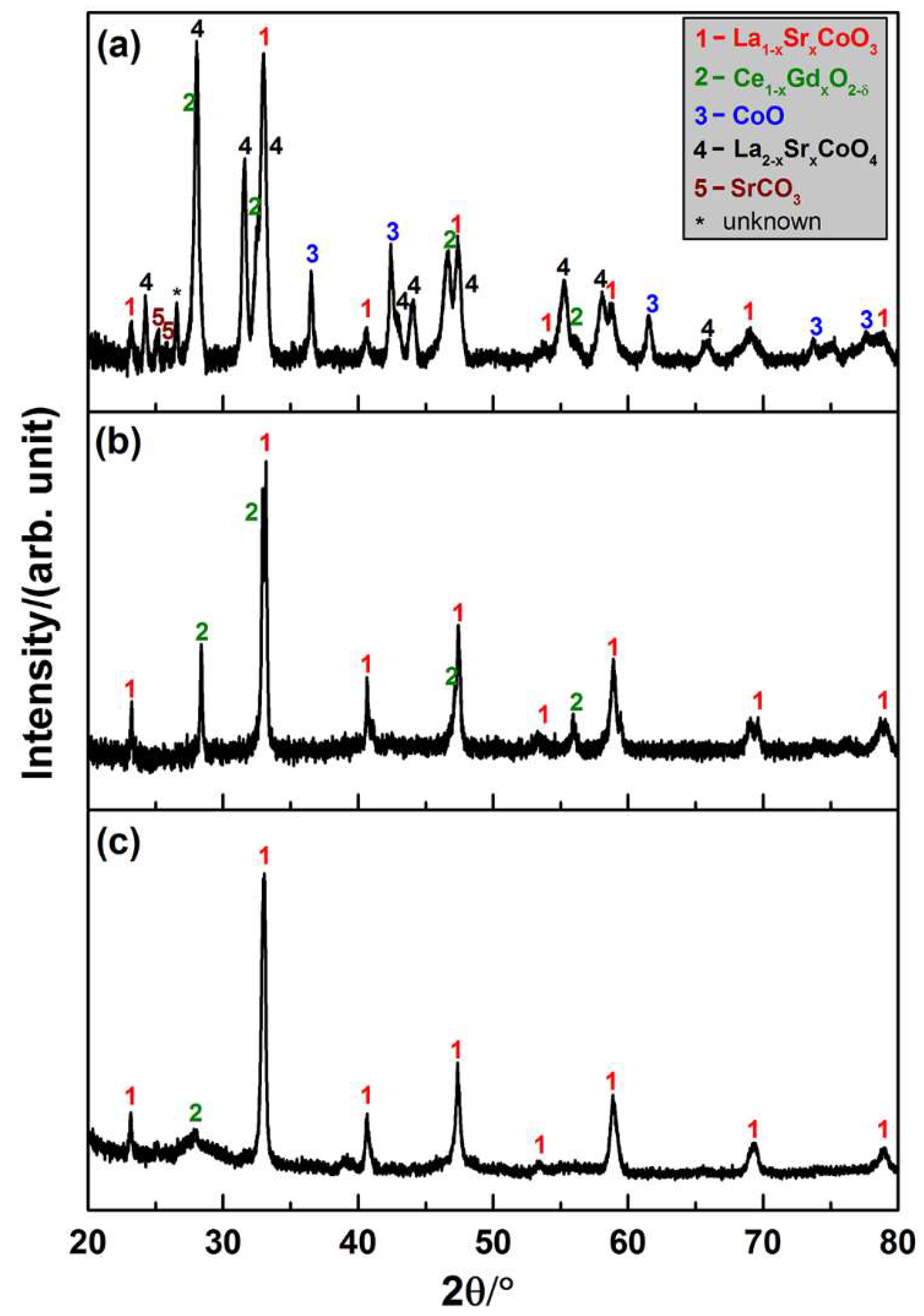
3.2.1. Phase Stability in the Sintering Processes

To determine the phases in the composite after densification of the LSC-CGO core-shell particles by SPS, part of the sintered composite was ground to a powder for XRD characterization. The pattern in Figure 3a is presented in comparison with that of the LSC-CGO core-shell particles before sintering in Figure 3c. Both the reflections corresponding to the perovskite-type La1−xSrxCoO3 with a rhombohedral crystal (space group: R-3c) and the fluorite-type cubic Ce1−xGdxO2−δ (space group: Fm-3m) were observed in the pattern of the sintered pellet. However, diffraction peaks from the cubic Ce1−xGdxO2−δ become sharp compared with those found in the pattern of LSC-CGO particles before sintering. Given that the sintering was conducted at 1000 °C, it was expected that the high temperature drove the growth of CGO nanocrystals. Apart from these two phases that already existed in the core-shell particles, new phases also formed during the SPS process. Diffraction peaks derived from CoO with a cubic crystal (space group: Fm-3m) and La2−xSrxCoO4 can be identified from the XRD pattern of the sintered pellet. Since (La0.6Sr0.4)0.99CoO3 provided the sole source of Co, the newly formed CoO phase must come from the decomposition of (La0.6Sr0.4)0.99CoO3. La2−xSrxCoO4 was the other decomposition product, which is known as a layered perovskite oxide and adopts the K2NiF4-type structure composed of [CoO6] corner-shared layers separated by pairs of (La,Sr)O layers [23]. Variation on the levels of Sr doping can cause a structural distortion of La2−xSrxCoO4 from the orthorhombic (x = 0) to the tetragonal (x = 1) and their reflections in XRD are very similar and are thus rather difficult to distinguish. From the viewpoint of application of the material as an electrode in an SOFC or SOEC, the decomposition is not adverse since the oxygen surface exchange rate would be remarkably increased at the heterogeneous interface between La2−xSrxCoO4 and La1−xSrxCoO3 [24]. The phase stability of the doped lanthanum cobaltites is sensitive to the stoichiometric composition, temperature and partial oxygen pressure [25]. By in-situ X-ray diffraction, previous research [26] determined the influence of oxygen partial pressure on the phase stability and found that in 10−4 and 10−5 atm oxygen the La0.6Sr0.4CoO3 started to decompose to CoO and LaSrCoO4 at 1000 °C and 950 °C respectively, and the new phases were kept while cooling down to room temperature. In the current case, the chamber was kept in a constant vacuum corresponding to 1.3 × 10⁻⁵ atm oxygen during the entire SPS process. Under such a low oxygen partial pressure, the (La0.6Sr0.4)0.99 CoO3 would, therefore, decompose after the temperature exceeded the threshold (~950 °C [26]). The two new phases were also found to be stable and to persist until the room temperature. In addition, peaks corresponding to SrCO3 can be found in the XRD pattern, which might come from complex reactions during the sintering.
The XRD characterization was also conducted on powders obtained by grinding the pellet densified by conventional sintering in air (see Figure 3b). Only two phases, rhombohedral LSC and cubic CGO, were observed, indicating that they were preserved from the hydrothermally synthesized core-shell particles to the sintered composite. Similar to the case in the SPS, the CGO nanocrystals grew during the sintering process, which resulted in sharp diffraction peaks in the pattern of the sintered pellet compared with the broad ones in that of LSC-CGO core-shell particles before sintering. In contrast, the LSC seemed to be phase stable under the applied conditions of the conventional sintering, as no peaks derived from a new crystallite phase appeared in the XRD pattern after sintering. Figure S6 in the supplementary material presents details on fitting peaks to the references in the database.

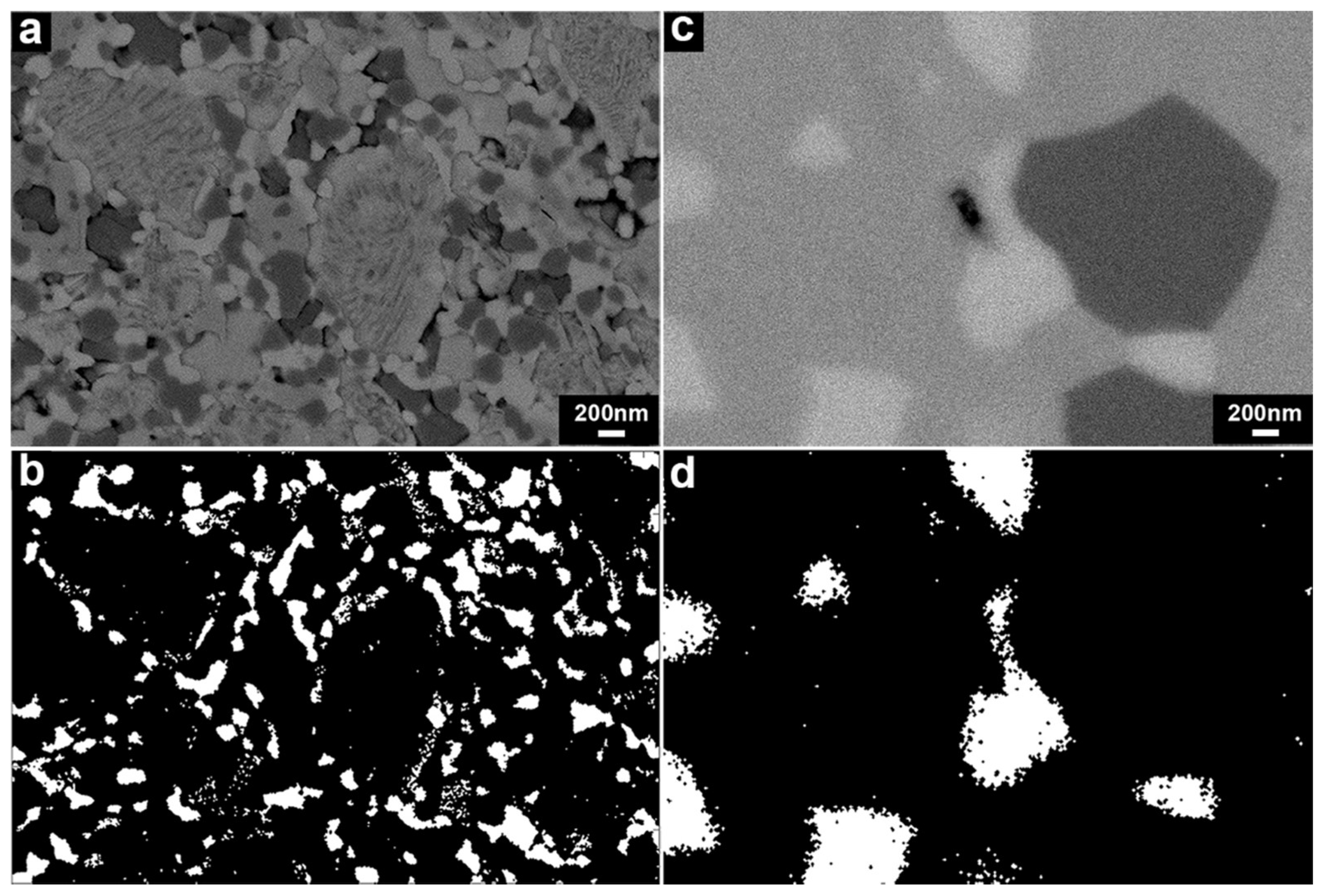
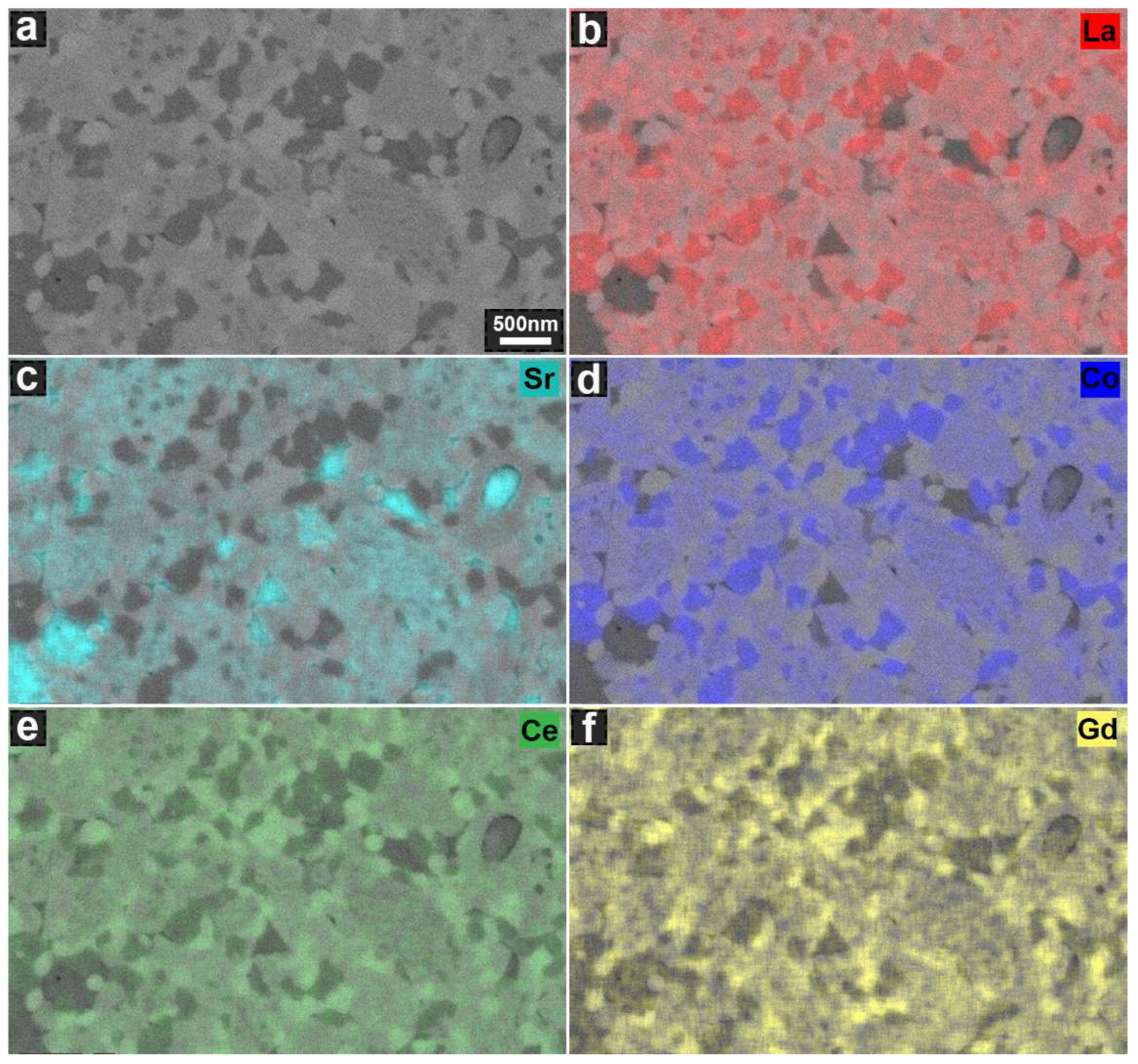
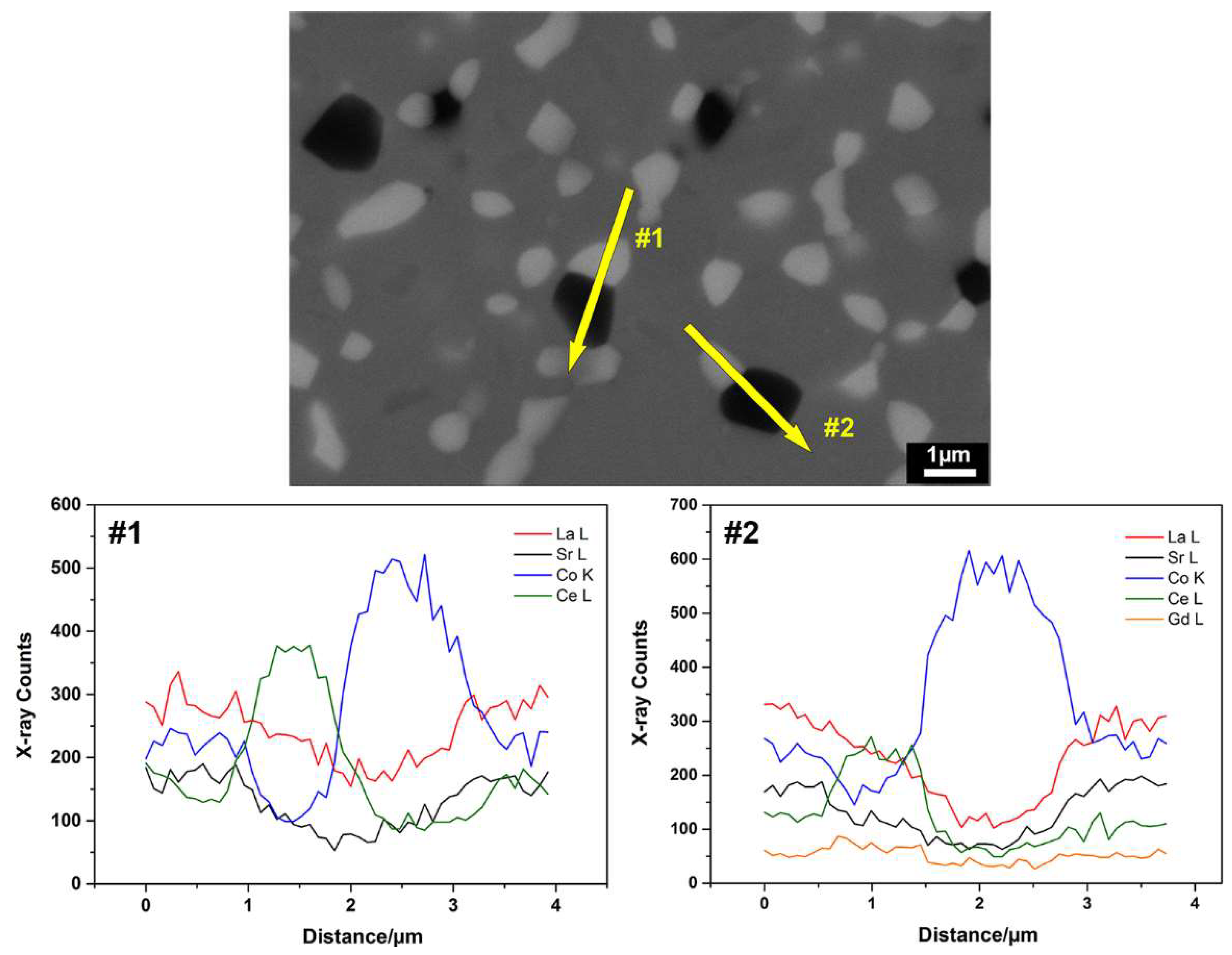
3.2.2. Microstructure

SEM-BSE images on the polished cross-sections of the samples densified by SPS and conventional sintering are presented in Figure 4a,c. The SPS-densified sample exhibited a much finer microstructure compared with the sample obtained by conventional sintering.
The LSC-CGO composite sintered by SPS was fully dense as no clear pores could be observed. Three phases of different contrasts (i.e., three scales of grey) could be identified in the SEM-BSE image (Figure 4a). To determine the composition of the three phases, EDS was conducted and the distribution of elements was mapped (Figure 5). As seen in Figure 5, the brightest phase observed in Figure 4a had high concentrations of Ce and Gd, while high concentrations of La, Sr and Co were found in the slightly darker grey phase. The darkest grey areas appeared to correspond to two different compositions, one composed of La, Co and the other enriched in Sr, indicating that Sr was segregated from the others after sintering. When comparing the element maps with the XRD results, it can be concluded that in Figure 4a the brightest grey phase was CGO, while the others that are darker grey were the LSC and its localized decomposition products. In addition, the CGO phase, distinguished by contrast, was located in the microstructure (Figure 4a) of the LSC-CGO composite by means of image segmentation, as an example presented in Figure 4b. Analysis of 10 segmentation images showed that the mean grain size of CGO was 87 ± 7 nm after densification by SPS (the other images and details on the image segmentation and on the grain size analysis are given in the supplementary material). Comparing the size of the CGO grains in the densified sample (mean diameter = 87 ± 7 nm) and the size of the CGO particles in the shell of initial LSC-CGO core-shell particles (mean diameter = 6 ± 1 nm) shows that the CGO coarsened during the SPS sintering, as also concluded from the XRD analysis. In the SPS-densified sample, most of the CGO phase was still distributed around the LSC and its decomposition products (Figure 4b), which means that the core-shell structure of the initial powders was partly preserved in the dense sample. However, the connectivity of the CGO phase was reduced, which might be due to the shrinkage of the CGO phase during sintering and the consumption of neighboring CGO during the CGO grain coarsening.
The microstructure of the LSC-CGO sample (relative density ≥ 99%) densified by conventional sintering also exhibited three phases that are distinguishable by the contrast (Figure 4c). Compositional analysis, described by the line distribution of elements obtained from SEM-EDS (Figure 6), indicates that the compositions of Ce and Gd peaked at the brightest grey phase, similar to the observation in the microstructure of the SPS-densified sample. In comparison, the darker grey phases had relatively high concentrations of La, Sr and Co. Moreover, the darkest grey phase was highly concentrated in Co, indicating that the chemical composition of the LSC varied during the sintering process. The Co-rich phase was also reported for the LSC-CGO composite samples obtained by mixing of LSC and CGO powders and sintering in air [27]. However, the depletion and enrichment of Co from the original LSC perovskite phase possibly did not result in phase transitions, since within the XRD detection limit only diffraction peaks derived from LSC and CGO were observed in the pattern (Figure 3c). A comparison between the XRD and the EDS results, therefore, indicates that the brightest grey phase was CGO, while the darker grey phases were LSC of different elemental compositions. Similarly, the CGO was located by means of segmentation of the microstructure of the LSC-CGO sample (Figure 4c) sintered conventionally, exemplarily shown in Figure 4d. Analysis of eight segmented images gave a mean CGO grain size of 384 ± 78 nm. Compared with those in the microstructure of the SPS-densified sample (mean grain size = 87 ± 7 nm), the CGO grains were coarser and are more isolated from each other.
As described above, the two sintered LSC-CGO samples displayed different microstructures. Given that the same LSC-CGO core-shell particles were used as a starting point, possible effects of initial particle morphology, size distribution or agglomeration state on the final microstructure can be excluded. The different sintering conditions alone can explain the differences in the final microstructure. In general, sintering is defined as a process where interparticle pores are removed by thermally activated atomic diffusions. Two competing processes, densification and coarsening, occur during the sintering process [28] and it is known that the coarsening should be suppressed if a ceramic body with a high density is targeted. Both LSC-CGO samples densified by SPS and conventional sintering displayed dense microstructures, indicating that the densification process was completed by both sintering methods. In principle, nanoparticles display a higher sinterability, because the driving force for densification is usually enhanced due to the high surface energy, fast atomic diffusion and large curvature [29]. In the initial stage of the sintering of LSC-CGO core-shell particles, the particles contacted with each other by the shell that was composed of large amounts of CGO nanoparticles, which resulted in a large driving force for densification. On the other hand, the grain coarsening commonly observed in powder sintering was also found, especially for CGO grains that derived from CGO nanoparticles of the initial core-shell particles. However, when looking at the CGO grains in the final microstructures, they were finer in the SPS-densified sample than in the conventionally sintered sample. In addition, the size of CGO grains was more homogeneous in the SPS-densified sample (standard deviation of mean grain size = 7 nm) whereas it varied largely in the conventionally sintered sample (standard deviation of mean grain size = 78 nm). This indicates that the coarsening was more pronounced in the conventional sintering process compared with the SPS, which can be due to the higher sintering temperature (1250 °C compared to 1000 °C for SPS) and a long stay in the high temperature range (6 h compared to 6 min for SPS) that was applied in the conventional sintering process. The diffusion mechanism of the grain coarsening is Ostwald ripening [30], meaning that the growth of bigger CGO grains would come at a cost of consuming the neighboring small CGO grains. This possibly explains the reduced percolation of CGO grains after sintering in both cases and that CGO grains were more isolated in the conventionally sintered composite than in the SPS-densified composite.
To summarize, for both sintering methods, the LSC-CGO core-shell particles were sintered into highly dense composites. By using SPS, it was possible to realize a fine structure with CGO nanograins and to preserve the original prearranged core-shell structure partially in the final densified composite. However, the low oxygen partial pressure during the SPS caused the decomposition of LSC and resulted in the formation of new crystalline phases. In comparison, conventional sintering of LSC-CGO core-shell particles conducted at different conditions resulted in a coarse microstructure, where pronounced CGO grain growth was observed. It is worth mentioning that SPS is currently limited to the sintering of relatively small-size samples. However, the work presented here shows that SPS can be a promising fabrication method for nanostructured LSC-CGO composites for different applications, once this limitation is addressed because obtaining such microstructures by conventional sintering is not possible.

3.3. Analysis of the SPS-densified LSC-CGO Composite after Thermal Cycling

The SPS-densified LSC-CGO composite was heat-treated at 700 °C for 1 h in air. Phases including La1−xSrxCoO3, Ce1−xGdxO2−δ as well as La2−xSrxCoO4 were preserved after the thermal cycling, shown by the XRD pattern of the composite after the heat treatment (Figure 7a). However, CoO, found in the SPS-densified composite as one of the LSC decomposition products, was oxidized to Co3O4. SrCO3 seemed decomposed in the thermal treatment, as rather weak corresponding peaks are observed in the pattern. An exemplary SEM-BSE micrograph (Figure 7b) presents the microstructure of the LSC-CGO composite after the thermal cycling. Similar to the observation in the as-sintered SPS-densified sample, phases of different contrasts can be found, corresponding to CGO, LSC and its decomposition products. Analyzing 9 images in total gave a mean CGO grain size of 109(±16) nm, indicating a small grain growth during the thermal treatment (the CGO grain size is 87(±7) nm in the as-sintered composites). Similar trends were found for the grain size of LSC and its decomposition products. Here, the mean grain size increased from 274(±31) nm to 428(±73) nm during the thermal cycling.

4. Conclusions

(La0.6Sr0.4)0.99CoO3-Ce0.8Gd0.2O1.9 particles with a core-shell structure were prepared by precipitating Ce0.8Gd0.2O1.9 nanoparticles on the surface of (La0.6Sr0.4)0.99CoO3 particles. The integral shell, composed of ~6 nm large Ce0.8Gd0.2O1.9 nanoparticles, was prepared under mild hydrothermal conditions at 100 °C. The microstructural evolution of core-shell particles was investigated under two different sintering conditions (spark plasma sintering and conventional sintering). In both cases, highly dense composites were obtained. It was found that a fine microstructure containing nanograins was obtained by spark plasma sintering, as well as the graded core-shell architecture was partially maintained. Phase transitions of (La0.6Sr0.4)0.99CoO3 under the low oxygen partial pressure during spark plasma sintering resulted in the formation of La2−xSrCoO4, which however is not necessarily adverse for application in oxygen transport membranes or solid oxide cells. In comparison, the grain coarsening process was more pronounced when the core-shell particles were densified by conventional sintering. As a result, coarse grains were found and the core-shell structure was lost in the final microstructure of the composite sintered conventionally. Further work will focus on understanding the effects of the novel microstructure on the physical properties (e.g., electric and ionic conductivity, oxygen permeability) of the composite.

Supplementary Materials

The following are available online at www.mdpi.com/xxx/s1, Figure S1: Particle size distribution of the commercial (La0.6Sr0.4)0.99CoO3 powder, Figure S2: Profiles of the spark plasma sintering of core-shell particles, Figure S3: The programmed temperature profile of the conventional sintering of core-shell particles, Figure S4: Two additional BF-TEM images of two other core-shell particles, Figure S5: A screenshot presenting the FFT of a high-resolution image of the Ce0.8Gd0.2O2 shell and measurements of distances from rings to the concentric center under the reciprocal space; the FFT was done by the Digital Micrograph; the scale bare in the high-resolution TEM image is 5 nm, Figure S6: Screenshots of the XRD peak fittings in the software, 2θ = 20-90°; (a) (La0.6Sr0.4)CoO3 (space group R-3c, PDF 01-089-5718); (b) Ce0.8Gd0.2O1.9 (space group Fm-3m, PDF 01-075-0162); (c) and (d) correspond to the tetragonal (x=1, space group I4/mmm, PDF 83-2412) and the orthorhombic (x=0, space group Abma, PDF 01-072-0937) La2-xSrxCoO4; (e) CoO (space group Fm-3m, PDF 01-075-0533) and (f) SrCO3 (space group Pnma, PDF 01-074-1419), Figure S7: A screenshot of the window of the ThreshAlyzer with an example; from left to right, top: intensity histogram, input image and measure scale bar, and final segmentation; bottom: threshold segmentation, ROI (region of interest) for smaller area analysis, and toggles, Figure S8: (a) a SEM-BSE image of the polished cross section of the sample of spark plasma sintered LSC-CGO core-shell particles; (b) the border of the white CGO grains is outlined after setting a threshold in the intensity histogram, which can be used as a guide to evaluate the reasonability of the threshold setting values; (c) the final segmentation of the SEM-BSE image, where the CGO grains are highlighted among the others; (d) and (e) present the histograms of ‘grain size vs covered volume ratio’ for CGO grains and grains of LSC and decomposition products; D50 and D90 mean a cumulative 50vol% and 90vol% point of diameter respectively, Figure S9: SEM-BSE images of two areas on the polished cross section of the SPS-densified sample; all selected points for EDS analysis are labeled by cross lines, Figure S10: (a) a SEM-BSE image of the polished cross section of the LSC-CGO sample densified by conventional sintering; (b), (c) and (d) are element maps of La Lα, Co Kα and Ce Lα, respectively, Figure S11: a-c (scale bar 200 nm) are three independent areas of the SPS-densified sample, and d-e (scale bar 1 μm, 1 μm and 2 μm separately) are three independent areas of the sample densified by the conventional sintering. All images were recorded by processing BSEs, Figure S12: Fracture surface of the samples densified by SPS (a and b) and by conventional sintering (c and d). For each selected area, SE2 and BSE images were recorded simultaneously, Table S1: Rietveld refinement residuals of the diffraction pattern of the raw commercial (La0.6Sr0.4)0.99CoO3 powder, Table S2: Rietveld refinement residuals of the diffraction pattern of the (La0.6Sr0.4)0.99CoO3-Ce0.8Gd0.2O1.9 core-shell powder, Table S3: A summary of the D50 and D90 for all grains by analyzing 10 SEM-BSE images of the polished cross section of the SPS-densified LSC-CGO sample, Table S4: A summary of the D50 and D90 for CGO grains by analyzing 8 SEM-BSE images of the polished cross section of the LSC-CGO sample densified by conventional sintering, Table S5: A summary of the D50 and D90 for all grains by analyzing 9 SEM-BSE images of the polished cross section of the SPS-densified LSC-CGO sample after thermal treatment, Table S6: Atomic compositions determined by the point EDS analysis (unit: atomic percent).

Author Contributions

Conceptualization, H.L., W.B. and R.K.; Methodology, Y.X., P.Z., N.V.N., S.P. and X.S.; Software, S.B.S. and P.N.; Formal Analysis, Y.X., S.P. and R.R.; Writing-Original Draft Preparation, Y.X.; Writing-Review & Editing, P.Z., N.V.N., S.P., R.R., S.B.S., P.N., W.B. and R.K.; Supervision, P.Z., S.B.S., P.N. and R.K.; Project Administration, R.K.; Funding Acquisition, R.K.

Funding

This research was funded by Danmarks Frie Forskningsfond grant number DFF 1335-00138.

Acknowledgments

The authors thank the Danish Council for Independent Research for funding within the ProEco project (DFF 1335-00138). The authors also thank Peter Stanley Jørgensen ([email protected]) for developing the software ThreshAlyzer used for analyzing the SEM images.

Conflicts of Interest

The authors declare no conflicts of interest.

References

  1. Schärtl, W. Current directions in core–shell nanoparticle design. Nanoscale 2010, 2, 829–843. [Google Scholar] [CrossRef] [PubMed]
  2. Wei, S.; Wang, Q.; Zhu, J.; Sun, L.; Lin, H.; Guo, Z. Multifunctional composite core–shell nanoparticles. Nanoscale 2011, 3, 4474–4502. [Google Scholar] [CrossRef] [PubMed]
  3. Ghosh Chaudhuri, R.; Paria, S. Core/shell nanoparticles: Classes, properties, synthesis mechanisms, characterization, and applications. Chem. Rev. 2012, 112, 2373–2433. [Google Scholar] [CrossRef] [PubMed]
  4. Jiang, Z.; Xia, C.; Chen, F. Nano-structured composite cathodes for intermediate-temperature solid oxide fuel cells via an infiltration/impregnation technique. Electrochim. Acta 2010, 55, 3595–3605. [Google Scholar] [CrossRef]
  5. Manthiram, A.; Kim, J.-H.; Kim, Y.N.; Lee, K.-T. Crystal chemistry and properties of mixed ionic-electronic conductors. J. Electroceram. 2011, 27, 93–107. [Google Scholar] [CrossRef]
  6. Ebbesen, S.D.; Jensen, S.H.; Hauch, A.; Mogensen, M.B. High temperature electrolysis in alkaline cells, solid proton conducting cells, and solid oxide cells. Chem. Rev. 2014, 114, 10697–10734. [Google Scholar] [CrossRef] [PubMed]
  7. Chen, P.-L.; Chen, I.-W. Grain growth in CeO2: Dopant effects, defect mechanism, and solute drag. J. Am. Ceram. Soc. 1996, 79, 1793–1800. [Google Scholar] [CrossRef]
  8. Datta, P. Doped ceria based solid oxide fuel cell electrolytes and their sintering aspects: An overview. Mater. Sci. Forum 2016, 835, 199–236. [Google Scholar] [CrossRef]
  9. Sun, C.; Hui, R.; Roller, J. Cathode materials for solid oxide fuel cells: A review. J. Solid State Electrochem. 2010, 14, 1125–1144. [Google Scholar] [CrossRef]
  10. Fang, S.; Chen, C.; Winnubst, L. Effect of microstructure and catalyst coating on the oxygen permeability of a novel CO2-resistant composite membrane. Solid State Ion. 2011, 190, 46–52. [Google Scholar] [CrossRef]
  11. Joo, J.H.; Yun, K.S.; Kim, J.-H.; Lee, Y.; Yoo, C.-Y.; Yu, J.H. Substantial oxygen flux in dual-phase membrane of ceria and pure electronic conductor by tailoring the surface. ACS Appl. Mater. Interfaces 2015, 7, 14699–14707. [Google Scholar] [CrossRef] [PubMed]
  12. Ibáñez, M.; Zamani, R.; Gorsse, S.; Fan, J.; Ortega, S.; Cadavid, D.; Morante, J.R.; Arbiol, J.; Cabot, A. Core–shell nanoparticles as building blocks for the bottom-up production of functional nanocomposites: PbTe–PbS thermoelectric properties. ACS Nano 2013, 7, 2573–2586. [Google Scholar] [CrossRef] [PubMed]
  13. Hu, C.; Liu, Y.; Liu, P.; Zhang, W.; Zhu, J. Microwave dielectric properties of (1 − x)SiO2-xTiO2 composite ceramics derived from core-shell structured microspheres. Mater. Res. Bull. 2014, 53, 54–57. [Google Scholar] [CrossRef]
  14. Mojić-Lanté, B.; Vukmirović, J.; Giannakopoulos, K.P.; Gautam, D.; Kukovecz, A.; Srdić, V.V. Influence of synthesis conditions on formation of core–shell titanate–ferrite particles and processing of composite ceramics. Ceram. Int. 2015, 41, 1437–1445. [Google Scholar] [CrossRef]
  15. Suarez, M.; Fernandez, A.; Menendez, J.L.; Torrecillas, R.; Kessel, H.; Hennicke, J.; Kirchner, R.; van Kessel, H. Challenges and Opportunities for Spark Plasma Sintering: A Key Technology for a New Generation of Materials. In Sintering Applications; Ertug, B., Ed.; InTech: Munich, Germany, 2013; ISBN 978-953-51-0974-7. [Google Scholar] [Green Version]
  16. Munir, Z.A.; Anselmi-Tamburini, U.; Ohyanagi, M. The effect of electric field and pressure on the synthesis and consolidation of materials: A review of the spark plasma sintering method. J. Mater. Sci. 2006, 41, 763–777. [Google Scholar] [CrossRef]
  17. Buscaglia, M.T.; Viviani, M.; Zhao, Z.; Buscaglia, V.; Nanni, P. Synthesis of BaTiO3 core-shell particles and fabrication of dielectric ceramics with local graded structure. Chem. Mater. 2006, 18, 4002–4010. [Google Scholar] [CrossRef]
  18. Basu, B.; Venkateswaran, T.; Kim, D.-Y. Microstructure and properties of spark plasma-sintered ZrO2–ZrB2 nanoceramic composites. J. Am. Ceram. Soc. 2006, 89, 2405–2412. [Google Scholar] [CrossRef]
  19. Rodríguez-Carvajal, J. Recent advances in magnetic structure determination by neutron powder diffraction. Phys. B Condens. Matter 1993, 192, 55–69. [Google Scholar] [CrossRef]
  20. Cote, L.J.; Teja, A.S.; Wilkinson, A.P.; Zhang, Z.J. Continuous hydrothermal synthesis of CoFe2O4 nanoparticles. Fluid Phase Equilibria 2003, 210, 307–317. [Google Scholar] [CrossRef]
  21. Sear, R.P. The non-classical nucleation of crystals: Microscopic mechanisms and applications to molecular crystals, ice and calcium carbonate. Int. Mater. Rev. 2012, 57, 328–356. [Google Scholar] [CrossRef]
  22. Sear, R.P. Quantitative studies of crystal nucleation at constant supersaturation: Experimental data and models. CrystEngComm 2014, 16, 6506–6522. [Google Scholar] [CrossRef]
  23. Tealdi, C.; Ferrara, C.; Mustarelli, P.; Saiful Islam, M. Vacancy and interstitial oxide ion migration in heavily doped La2−xSrxCoO4±δ. J. Mater. Chem. 2012, 22, 8969–8975. [Google Scholar] [CrossRef] [Green Version]
  24. Sase, M.; Hermes, F.; Yashiro, K.; Sato, K.; Mizusaki, J.; Kawada, T.; Sakai, N.; Yokokawa, H. Enhancement of oxygen surface exchange at the hetero-interface of (La,Sr)CoO3/(La,Sr)2CoO4 with PLD-layered films. J. Electrochem. Soc. 2008, 155, B793–B797. [Google Scholar] [CrossRef]
  25. Petrov, A.N.; Cherepanov, V.A.; Zuev, A.Y. Thermodynamics, defect structure, and charge transfer in doped lanthanum cobaltites: An overview. J. Solid State Electrochem. 2006, 10, 517–537. [Google Scholar] [CrossRef]
  26. Ovenstone, J.; White, J.S.; Misture, S.T. Phase transitions and phase decomposition of La1−xSrxCoO3−δ in low oxygen partial pressures. J. Power Sources 2008, 181, 56–61. [Google Scholar] [CrossRef]
  27. Samson, A.J.; Søgaard, M.; Vang Hendriksen, P. (Ce,Gd)O2−δ-based dual phase membranes for oxygen separation. J. Membr. Sci. 2014, 470, 178–188. [Google Scholar] [CrossRef]
  28. Chen, I.-W.; Wang, X.-H. Sintering dense nanocrystalline ceramics without final-stage grain growth. Nature 2000, 404, 168–171. [Google Scholar] [CrossRef] [PubMed]
  29. Rufner, J.; Anderson, D.; van Benthem, K.; Castro, R.H.R. Synthesis and sintering behavior of ultrafine (<10 nm) magnesium aluminate spinel nanoparticles. J. Am. Ceram. Soc. 2013, 96, 2077–2085. [Google Scholar] [CrossRef]
  30. Anselmi-Tamburini, U.; Garay, J.E.; Munir, Z.A. Fast low-temperature consolidation of bulk nanometric ceramic materials. Scr. Mater. 2006, 54, 823–828. [Google Scholar] [CrossRef]
Figure 1. (a) Rietveld refinement of the powder X-ray diffraction of the commercial lanthanum strontium cobaltite (LSC) powder; the observed pattern, the calculated pattern, Bragg positions and the differential profile are presented by red circles, the black line, blue vertical bars and the green line, respectively; (b) an SE2 image of the LSC powders; (c) Rietveld refinement of the powder X-ray diffraction of the particle composed of LSC core and the shell of gadolinium-doped ceria (CGO) before sintering; red vertical bars corresponding to Bragg positions of cubic CGO are added; (d) an SE2 image of the LSC-CGO particles before sintering.
Ceramics 01 00020 g001
Figure 2. (a) A BF-TEM image of the LSC-CGO core-shell particles; the first inset is an FFT of the shell composed of nanosized CGO particles randomly oriented; the second inset is a high-resolution image of a CGO nanoparticle in the shell. (b) a DF-STEM image of LSC-CGO particles; (c) Mapping of all involved metallic elements by STEM-EDS; X-ray photons from La Lα, Sr Kα, Co Kα, Ce Lα and Gd Lα.
Ceramics 01 00020 g002
Figure 3. Powder X-ray diffraction patterns of (a) LSC-CGO composite densified by SPS of core-shell particles; (b) LSC-CGO composite densified by conventional sintering of core-shell particles; (c) LSC-CGO core-shell particles before sintering.
Ceramics 01 00020 g003
Figure 4. (a) A BSE image of the polished cross-section of LSC-CGO densified by spark plasma sintering; (b) segmentation of the CGO phase observed in (a); (c) a BSE image of the polished cross-section of LSC-CGO densified by conventional sintering; (d) segmentation of the CGO phase observed in (c).
Ceramics 01 00020 g004
Figure 5. (a) A BSE image of the cross-section of the LSC-CGO composite densified by SPS recorded with a primary energy of 5 kV; (bf) SEM-EDS elemental maps of La L, Sr L, Co L, Ce L and Gd M.
Ceramics 01 00020 g005
Figure 6. A BSE image of the polished cross-section of the LSC-CGO sample by conventional sintering recorded with a primary energy of 15 kV and SEM-EDS element line distributions along two selected directions as indicated.
Ceramics 01 00020 g006
Figure 7. (a) XRD pattern of the SPS-densified LSC-CGO composite after the thermal cycle; (b) a BSE micrograph of the polished cross-section of the sample.
Ceramics 01 00020 g007

