Article

Design and Experimental Validation of a Self-Contained Rotating Halbach Array—Based Demonstrator for EDS Systems

Department of Mechatronics Engineering, Yildiz Technical University, 34349 Istanbul, Türkiye
*
Author to whom correspondence should be addressed.
Appl. Syst. Innov. 2026, 9(6), 128; https://doi.org/10.3390/asi9060128
Submission received: 5 May 2026 / Revised: 4 June 2026 / Accepted: 10 June 2026 / Published: 15 June 2026

Abstract

This paper presents the design and experimental validation of a self-contained rotating Halbach array—based demonstrator for electrodynamic suspension (EDS) systems. The proposed platform was developed to bridge the gap between conventional externally powered laboratory testbeds and large-scale EDS vehicles by enabling investigation of levitation behavior under realistic onboard mass and subsystem integration constraints. The system integrates rotating circular Halbach arrays, onboard power supply, sensing, motor control, and structural support within a single levitated architecture. Experimental validation was conducted under a constrained one-degree-of-freedom configuration allowing vertical motion only. The system achieved stable levitation of a 35 kg platform and supported additional payloads approaching a 1:2 ratio relative to the baseline mass, while maintaining air-gap stability within approximately ±0.1 mm. The experimental results further reveal that the operational limit of the system is governed by actuation power and current constraints rather than electromagnetic levitation capability, highlighting a key distinction between self-contained and externally powered EDS systems. The proposed demonstrator provides a compact and practical experimental platform for the validation and performance evaluation of Halbach-array-based EDS systems. In addition, the study presents practical engineering insights regarding payload distribution, actuator saturation, structural integration, and system-level design constraints relevant to future self-contained EDS platforms and control-oriented levitation systems.

1. Introduction

Electrodynamic suspension (EDS) systems have attracted significant attention in high-speed transportation due to their contactless operation, reduced mechanical wear, and suitability for ultra-high-speed regimes. Beyond conventional railway applications, EDS technology has gained increasing interest in emerging transportation concepts such as superconducting maglev trains and Hyperloop systems, where large operational air gaps, fail-safe characteristics, and reduced maintenance requirements provide significant advantages over conventional wheel–rail transportation. In addition, EDS principles have been investigated for cargo transportation, automated material handling systems, and other applications requiring contactless motion. These developments continue to motivate research aimed at improving the efficiency, stability, and practical implementation of EDS technologies [1,2,3,4].
EDS operates based on the interaction between a moving magnetic field source and induced eddy currents in a passive conductive guideway, generating repulsive Lorentz forces that provide levitation and guidance [5,6,7,8,9,10]. The system exhibits a strongly nonlinear speed-dependent behavior, where the levitation force increases with velocity and asymptotically saturates, while the magnetic drag force peaks at low speeds and decreases at higher velocities [5,11,12,13,14,15].
Although EDS systems provide inherent passive stability in the levitation direction without requiring active gap control, they are fundamentally underdamped due to low intrinsic magnetic damping, which can lead to severe vibration and dynamic instability at high speeds [4,6,16,17,18,19,20]. Compared to electromagnetic suspension (EMS) systems, which rely on actively controlled attractive forces and inherently unstable equilibria, EDS systems offer fail-safe operation and significantly larger air gaps, making them less sensitive to track irregularities and reducing infrastructure precision requirements [3,5,21,22,23,24].
Among various EDS configurations, permanent magnet-based systems utilizing Halbach arrays have emerged as a highly efficient solution due to their ability to concentrate magnetic flux on the active side while suppressing stray fields on the opposite side [12,25,26,27,28]. This field-shaping capability eliminates the need for heavy ferromagnetic back-irons, reducing system mass and improving overall efficiency [5,11,29]. Furthermore, well-designed Halbach geometries significantly enhance lift-to-drag and lift-to-weight ratios, enabling efficient force generation with minimal magnet volume [7,12,30,31,32,33]. Parametric optimization of design variables such as magnet fill factor, wavelength, and thickness has been shown to further reduce drag forces and power consumption, making Halbach-based EDS systems particularly attractive for compact and scalable implementations [11,12,26,30,34].
Extensive experimental research has been conducted to validate EDS systems using various laboratory-scale testbeds and full-scale prototypes. Rotating disk and drum-based test rigs are widely employed to emulate continuous relative motion and enable steady-state data acquisition without boundary effects [5,7,12,35]. These systems provide controlled environments for measuring lift and drag forces but inherently restrict the degrees of freedom and introduce curvature-related errors, limiting their ability to replicate realistic multi-axis vehicle dynamics [5,7,21]. Alternatively, linear short-track experiments enable direct evaluation of translational behavior but suffer from high infrastructure costs, limited steady-state operation, and strong end effects [6,7,21,36].
At the other end of the spectrum, full-scale prototypes such as superconducting maglev systems and Hyperloop demonstrators validate integrated levitation and propulsion performance under realistic operating conditions [2,3,5]. However, these systems require substantial infrastructure investments and lack the flexibility necessary for iterative experimental studies and component-level optimization [3,7,21,37].
Despite significant progress in both laboratory-scale and full-scale studies, a critical gap remains in the development of intermediate experimental platforms that capture the characteristics of self-contained, vehicle-like EDS systems. Existing testbeds are predominantly externally powered and mechanically constrained, decoupling levitation performance from onboard system components such as energy storage, control electronics, and payload effects [5,7,21,38]. Consequently, these setups fail to represent the coupled electro-mechanical dynamics and mass penalties inherent to realistic EDS vehicles. Conversely, full-scale systems incorporate these complexities but are not suitable for controlled experimental investigation or rapid design iteration.
In vehicle-level EDS architectures, particularly in low-infrastructure or capsule-based transportation concepts, systems are expected to operate as self-contained units incorporating onboard energy storage, propulsion mechanisms, sensing, and control subsystems [3,5,39]. However, integrating these components significantly increases system mass and exacerbates the inherently underdamped dynamic behavior of EDS systems, leading to complex multi-axis instabilities in pitch, roll, and yaw [6,16,40,41,42]. These challenges make experimental validation of fully unconstrained multi-DoF (degree-of-freedom) systems both technically difficult and potentially hazardous.
To address these challenges, this paper presents the design and experimental validation of a self-contained rotating Halbach array-based demonstrator for EDS systems. The proposed system integrates onboard power supply, sensing, and control components within the levitated structure, enabling the evaluation of realistic system-level constraints, including payload capacity and mass distribution effects. The levitation mechanism is realized using rotating Halbach arrays interacting with a stationary conductive plate, providing a compact and controllable experimental environment [43,44].
Due to the strong nonlinear coupling and instability risks associated with unconstrained EDS systems, the experimental validation is conducted under a constrained one-degree-of-freedom (1-DoF) configuration, allowing only vertical motion while restricting lateral and translational degrees of freedom. This approach enables the isolation of fundamental levitation characteristics, including air gap stability, load-carrying capacity, and intrinsic damping behavior, without interference from multi-axis dynamic coupling [6,7,29]. Such a stepwise validation strategy is widely recognized in the literature as a necessary approach for safely transitioning from simplified experimental setups to fully autonomous multi-DoF systems [6,21].
The proposed demonstrator bridges the gap between conventional stationary testbeds and full-scale EDS vehicles by providing a flexible, self-contained experimental platform for investigating coupled system dynamics under realistic constraints. The main scientific contributions of this work can be summarized as follows:
  • Design and implementation of a fully self-contained rotating Halbach-array-based EDS demonstrator integrating onboard power supply, sensing, motor control, and levitation subsystems within a single levitated architecture.
  • Experimental validation of stable levitation behavior under realistic onboard mass and payload conditions using a constrained 1-DoF configuration representative of vehicle-level system integration constraints.
  • System-level investigation of payload capacity, air-gap stability, actuator saturation behavior, and mass-distribution-induced asymmetries in a self-contained EDS platform.
  • Identification of actuator power and current limitations as the dominant operational boundary of the proposed system, highlighting a key distinction between externally powered laboratory testbeds and self-contained EDS architectures.
  • Presentation of practical engineering challenges, integration constraints, and design trade-offs associated with the development of compact self-contained EDS systems.
The remainder of this paper is organized as follows: Section 2 presents the principle of operation and electromagnetic optimization, Section 3 describes the design and integration of the self-contained demonstrator, Section 4 details the experimental methodology, and Section 5 presents the experimental results and discussion, followed by conclusions in Section 6.

2. Principle of Operation and Electromagnetic Optimization

2.1. Electrodynamic Levitation Principle

The proposed system operates based on electrodynamic suspension (EDS) generated by a rotating circular Halbach array positioned above a passive conductive plate. The rotation of the permanent magnet array produces a spatially varying and time-dependent magnetic field in the reference frame of the stationary track, resulting in the induction of eddy currents within the conductive medium.
According to Faraday’s law of electromagnetic induction, the time-varying magnetic flux induces circulating currents in the conductive plate, which can be expressed as
× E = B t , J = σ E ,
where σ denotes the electrical conductivity of the conductive plate. The interaction between the induced current density J and the magnetic flux density B generates a Lorentz force distribution within the conductor, given by
F = V ( J × B ) d V .
The vertical component of this force produces levitation, while the tangential component results in a resistive drag torque opposing the rotation of the magnetic array. In the present system, the rotational motion of the Halbach array is mapped to an equivalent linear velocity at the effective radius r 0 of the disk:
v = ω m r 0 ,
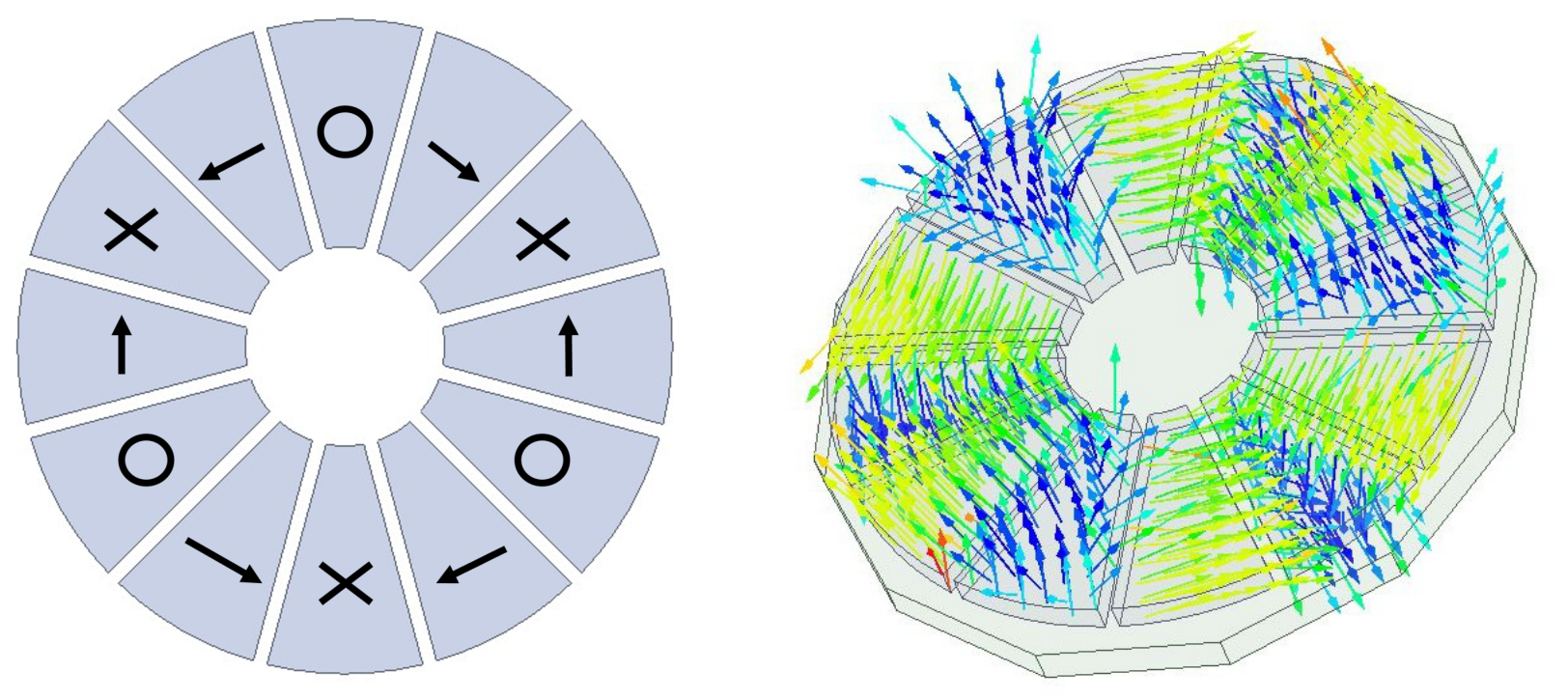
where ω m is the mechanical angular velocity. This equivalent velocity determines the frequency of magnetic field variation and directly governs the magnitude of induced currents and levitation force. The geometry of the circular Halbach array and the corresponding magnetic field distribution are illustrated in Figure 1.

2.2. Analytical Background of Lift and Drag Generation

Electrodynamic suspension systems generate levitation through the interaction between a moving magnetic field and the eddy currents induced in a conductive track. For permanent-magnet Halbach-array configurations, the resulting lift and drag forces can be approximated using analytical expressions derived from Faraday’s law, Lenz’s law, and equivalent circuit representations of the induced current paths [45,46,47].
For a Halbach array moving above a conductive plate, the lift force, F L , and drag force, F D , can be approximated as
F L = B 0 2 w 2 2 k L 1 1 + R ω L 2 e 2 k g
F D = B 0 2 w 2 2 k L R ω L 1 + R ω L 2 e 2 k g
where B 0 is the magnetic flux density, w is the effective magnet width, k is the spatial wave number, g is the levitation gap, and R and L represent the equivalent resistance and inductance of the induced current path, respectively.
These relationships indicate that both lift and drag are strongly dependent on the levitation gap through an exponential term, while the lift-to-drag ratio increases with operating speed. Consequently, higher speeds generally improve the efficiency of EDS systems by increasing the lift-to-drag ratio. At the same time, reductions in air gap increase both levitation force and drag-induced loading, highlighting the fundamental trade-off governing EDS operation.
Although these analytical expressions provide valuable physical insight into EDS operation, their accuracy is limited by simplifying assumptions such as idealized magnetic field distributions, uniform material properties, and the neglect of edge effects, skin-depth variations, and other nonlinear phenomena. Therefore, the equations presented here are intended only to illustrate the fundamental relationships governing lift and drag generation in EDS systems. Since the primary objective of this work is the design, implementation, and experimental validation of a self-contained EDS demonstrator, a detailed analytical formulation and comprehensive modeling of the underlying EDS dynamics are beyond the scope of the present study and will be addressed in future work.
The electrodynamic behavior of the proposed system was evaluated under a set of predefined design requirements related to payload capacity, conductive track geometry, and allowable operating duration. In particular, the demonstrator was designed for a target system mass of 80 kg and a conductive Al6101-T6 plate with dimensions compatible with laboratory-scale validation. In addition, the operational duration was limited to 60 s in order to remain within the thermal constraints of the selected conductive plate and drive components. This duration was defined as a conservative minimum design requirement during the system sizing stage. These requirements, summarized in Table 1, define the practical design space of the demonstrator and serve as the basis for the subsequent electromagnetic optimization. In addition, an acceptable air-gap deviation of ±0.5 mm was defined as a practical stability criterion for the demonstrator, considering mechanical tolerances, sensor resolution, and safe non-contact operation requirements.

2.3. Parametric Sensitivity Analysis of the Circular Halbach Array

The electromagnetic performance of the system is strongly dependent on the geometric parameters of the circular Halbach array. A parametric sensitivity analysis was conducted to determine the optimal configuration in terms of levitation capability and structural feasibility.
One of the primary design variables is the azimuthal segmentation, defined by the number of magnets used to approximate the Halbach distribution. Increasing the number of segments improves the approximation of the ideal rotating magnetic field and enhances the fundamental harmonic component. However, excessive segmentation leads to impractically thin magnet geometries, reducing mechanical robustness. Based on this trade-off, a 24-magnet configuration per disk was selected as a suitable design choice.
The axial thickness of the magnets was found to have a direct influence on the generated magnetic flux density. Increasing magnet thickness enhances the field strength and consequently increases the levitation force, although the benefit diminishes as the effective magnetic circuit approaches saturation.
The air gap between the rotating array and the conductive plate is another critical parameter. The levitation force exhibits an exponential decay with increasing air gap due to the rapid reduction in magnetic flux linkage. This behavior significantly limits the achievable lift force at larger separations and establishes a strong design constraint on the allowable operating gap.
The electromagnetic analyses were performed using the transient solver of ANSYS Maxwell 3D (Version 2019 R3) in order to capture the time-varying interaction between the rotating Halbach array and the conductive plate. The rotating motion of the disk was modeled using a rotational band approach around the global z-axis, while the conductive plate was modeled with eddy-current effects enabled to account for induced current formation and skin-effect behavior under varying rotational speeds. The simulations employed insulating boundary conditions enclosing the computational domain in order to minimize artificial field interactions at the domain boundaries. Electromagnetic force and magnetic drag torque were extracted directly from the conductive plate and magnet assemblies, respectively. A length-based mesh refinement strategy was applied to the magnets, conductive plate, and air-gap regions to ensure stable force convergence and accurate field resolution. In addition, parametric analyses were conducted through the ANSYS Optimetrics module by varying key geometric parameters of the Halbach array configuration.
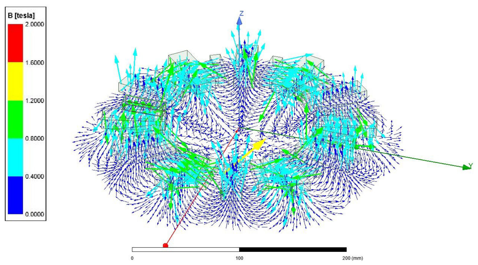
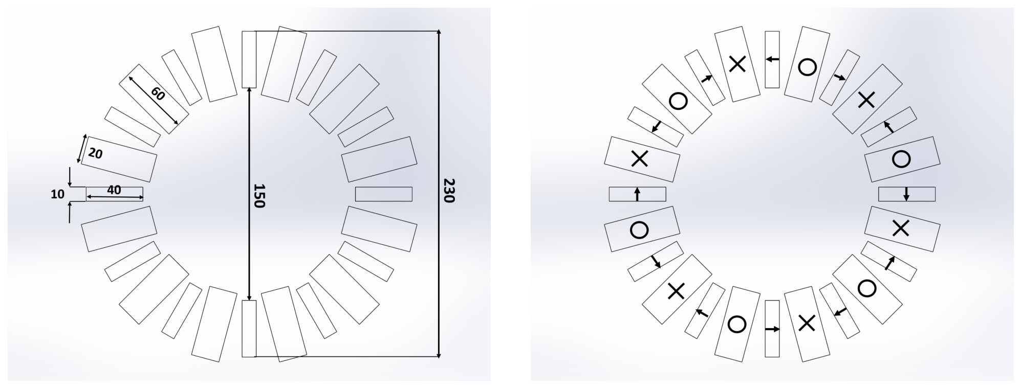
The resulting Halbach array geometry is illustrated in Figure 2 and Figure 3, showing the physical configuration and the corresponding asymmetric magnetic field distribution concentrated on the active side, which is characteristic of Halbach array configurations. Experimental magnetic flux density measurements were also conducted on both sides of the assembled disk using a gaussmeter in order to verify the flux concentration characteristic of the Halbach configuration. The measurements indicated peak magnetic flux densities of approximately 0.8 T on the active side and approximately 0.25 T on the passive side, confirming the asymmetric field distribution and effective magnetic field cancellation behavior illustrated in Figure 3.
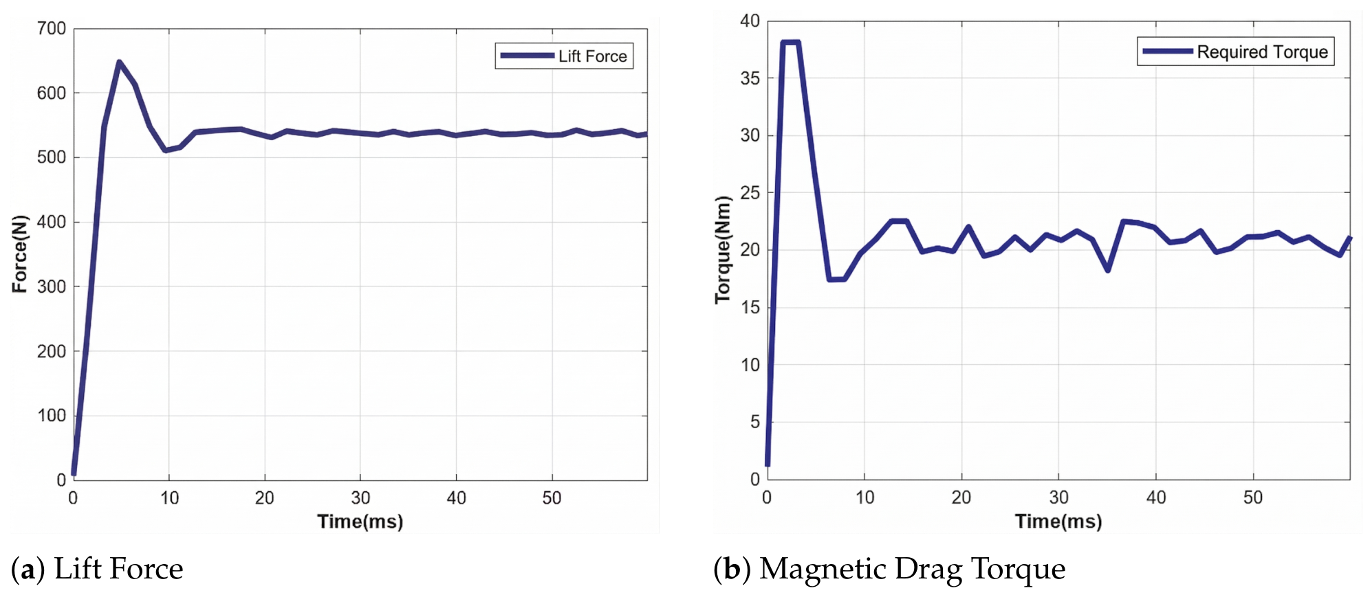
The electromagnetic performance of the selected configuration is presented in Figure 4. The simulation results confirm that the selected geometry provides sufficient levitation force while maintaining an acceptable magnetic drag torque, thereby validating its suitability for the final demonstrator design.
The transient responses presented in Figure 4 exhibit oscillatory behavior during the initial acceleration phase before converging toward steady-state conditions. From a control-oriented perspective, this behavior is characteristic of an underdamped open-loop dynamic response with strong coupling between electromagnetic force generation and drag-induced torque variations. The simulated lift-force response can be approximately represented by a classical second-order dynamic system with an estimated damping ratio of ζ 0.45 and natural frequency of ω n 800 rad / s . Accordingly, the response may be approximated by
G ( s ) = K ω n 2 s 2 + 2 ζ ω n s + ω n 2 = 3.46 × 10 8 s 2 + 720 s + 6.4 × 10 5 ,
where K denotes the steady-state gain, corresponding to a steady-state lift force of approximately 540 N for the simulated operating condition. These dynamic characteristics indicate that future closed-loop implementations may require high-bandwidth control strategies and sufficiently fast sensing-actuation loops in order to suppress transient oscillations and maintain stable air-gap regulation under varying operating conditions.
The final Halbach array parameters, selected based on parametric and sensitivity analysis, are summarized in Table 2. The selected magnet dimensions were determined by considering the combined requirements of magnetic field strength, manufacturability, mechanical robustness, and assembly feasibility. The larger 60 × 20 × 10 mm magnets provide the main radial flux contribution over the active region, while the smaller 40 × 10 × 10 mm magnets complete the 90° Halbach magnetization sequence within the available circular disk geometry. Rectangular magnet geometries were preferred over custom-shaped alternatives in order to simplify mechanical integration, improve assembly repeatability, and ensure practical manufacturability using commercially available permanent magnets. This combination allows sufficient magnetic field concentration while maintaining adequate spacing between adjacent magnets, which is necessary to reduce assembly difficulty and preserve structural integrity at high rotational speeds. The configuration employs NdFeB N35 permanent magnets due to their high remanent flux density, strong magnetic field concentration capability, wide commercial availability, and cost-effective implementation for scalable and reproducible experimental systems.

2.4. Determination of Operating Conditions: Rotational Speed and Air Gap

The relationship between rotational speed and levitation force exhibits a nonlinear behavior characteristic of electrodynamic suspension systems. At low rotational speeds, the levitation force increases rapidly with speed due to the increasing rate of magnetic field variation. However, at higher speeds, the force approaches a saturation limit as a result of the skin effect, which confines the induced eddy currents to a thin surface layer of the conductor.
In parallel, the magnetic drag torque reaches a peak value during the initial acceleration phase and decreases at higher speeds. This behavior implies that operating the system at sufficiently high rotational speeds reduces the continuous torque demand on the motor, thereby improving overall efficiency.
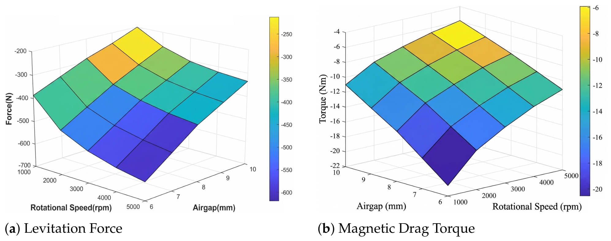
This coupled behavior is illustrated in Figure 5, which presents the variation of levitation force and magnetic drag torque as functions of rotational speed and air gap for the selected Halbach array configuration. It should be noted that the levitation force values appear with opposite signs in the presented figures due to the selected simulation reference frame. For numerical convenience, the simulations were performed by rotating the conductive plate instead of the Halbach disk. Consequently, the calculated electromagnetic force acts downward on the conductive plate, resulting in negative force values according to the selected coordinate system. However, the corresponding levitation force acting on the rotating Halbach disk is equal in magnitude and opposite in direction, representing the positive lifting force observed in the physical system.
Based on the combined analysis of levitation force, drag torque, and system constraints, a suitable operating region was identified within a rotational speed range of 3500–4000 rpm and an air gap of 12–13 mm. Within this envelope, each disk is capable of generating approximately 300 N of lift while maintaining the required torque within the continuous operating limits of the selected actuation system. This region represents a practical trade-off between levitation performance and energy efficiency for the proposed demonstrator.

3. Self-Contained Demonstrator Architecture

3.1. Mechanical Design and Structural Integrity

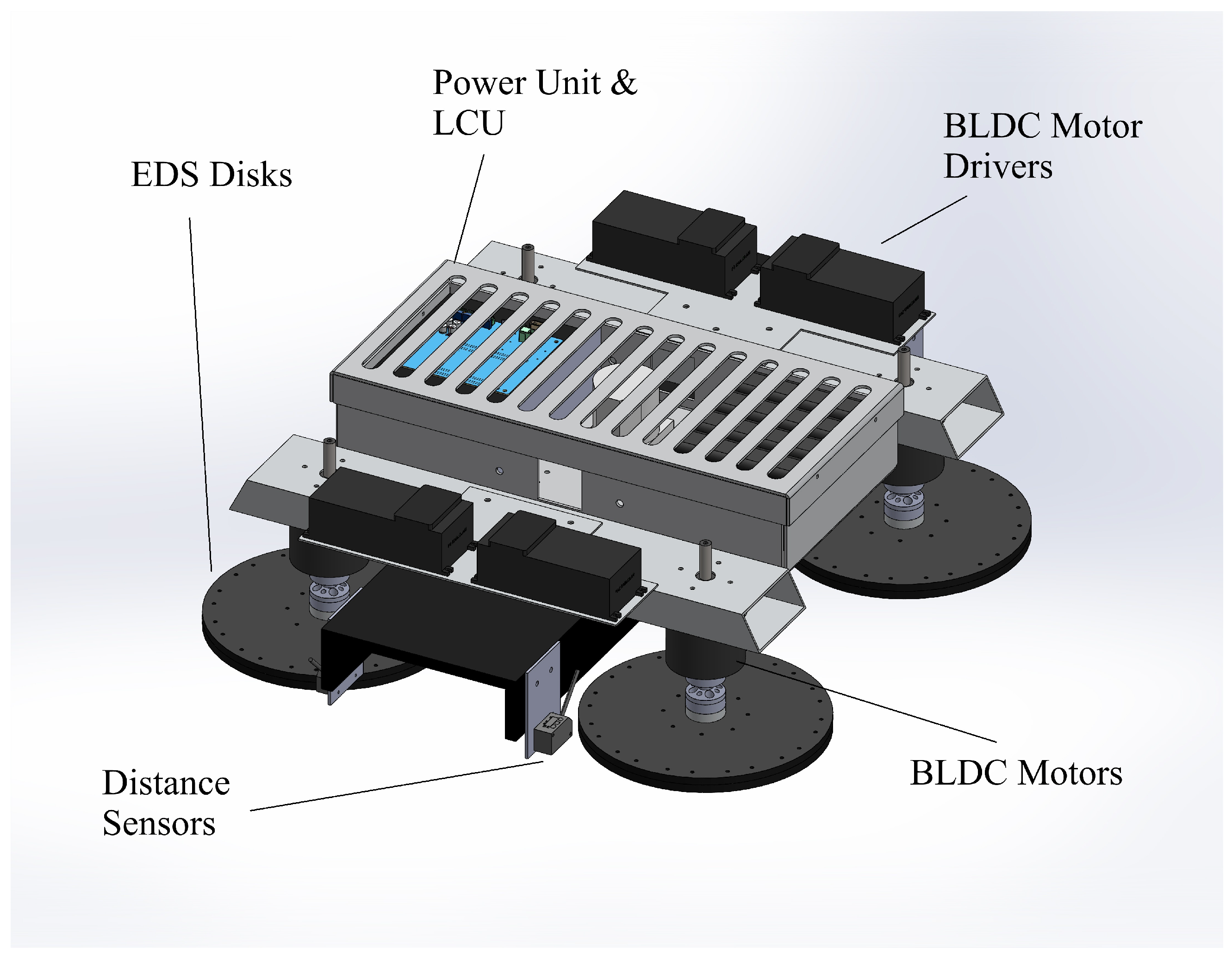
The mechanical architecture of the proposed demonstrator was designed to ensure high structural rigidity, geometric precision, and safe operation under extreme rotational loading conditions. The overall architecture of the self-contained demonstrator, including the EDS disks, BLDC motors, motor drivers, power unit, and sensing components, is illustrated in Figure 6. The system is built around a lightweight yet stiff primary chassis, which serves as the structural backbone for all subsystems.
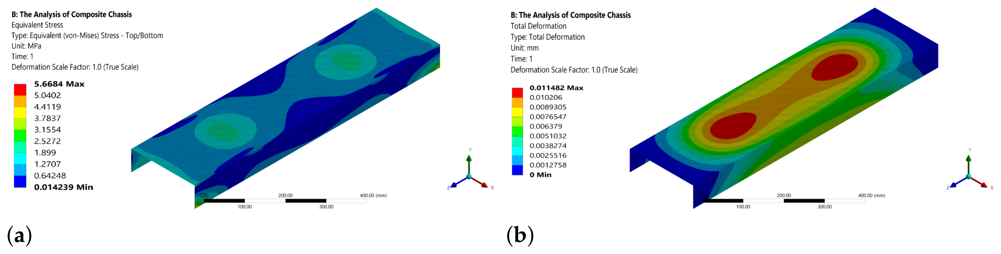
The main chassis is manufactured using a sandwich-structured carbon epoxy composite with a U-profile geometry. This configuration was selected to maximize bending stiffness while minimizing structural mass, resulting in a total chassis weight of approximately 3.0 kg. The high stiffness-to-weight ratio enables the entire platform to behave as a quasi-rigid body, which is critical for maintaining consistent air-gap conditions during operation. Finite element analysis results of the chassis, shown in Figure 7, confirm high global stiffness and elastic behavior under representative operational loading conditions, with a maximum total deformation of approximately 0.011 mm and a maximum equivalent stress of 5.67 MPa.
The rotating EDS disks, which constitute the core levitation elements, are fabricated from POM Delrin polymer. This material was selected due to its non-magnetic and electrically non-conductive nature, high dimensional stability, and favorable mechanical properties under dynamic loading. These properties prevent parasitic electromagnetic interactions, thereby reducing losses during high-speed rotation.
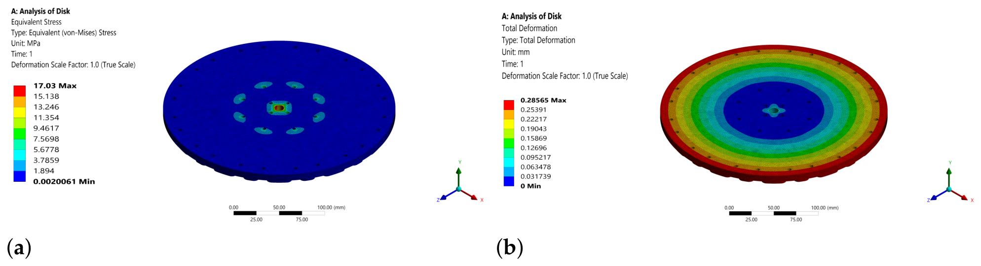
Structural analyses of the composite chassis and rotating EDS disks were performed in ANSYS Workbench using a static structural analysis under representative operational loading conditions. The simulations were conducted to evaluate the equivalent stress distribution and total elastic deformation of the structural components under combined lift, centrifugal, torque, and support loads. The applied loading conditions were determined based on the expected operational forces acting on the demonstrator during levitation experiments. A standard solid-element mesh with local refinement in critical regions was employed to ensure sufficient stress and deformation resolution. As illustrated in Figure 8a,b, the analysis revealed that the system experiences a total centrifugal load of approximately 72 kN, while the maximum equivalent stress and total deformation remain limited to 17.03 MPa and 0.29 mm, respectively. These values indicate that the disk structure preserves the geometric tolerances required for stable levitation and accurate air-gap measurement under operational conditions.
A critical design consideration was the mechanical reliability of the magnet retention mechanism. To mitigate the risk of adhesive failure under high centripetal acceleration, a two-part disk architecture was implemented. In this configuration, a lower retaining disk structurally supports and isolates the active magnetic array, preventing catastrophic magnet detachment and ensuring safe operation.
The integration of actuation and sensing components was achieved through structurally robust mounting elements. The BLDC motors are rigidly connected to the chassis using box-profile brackets manufactured from Al7075 aluminum alloy. These brackets exhibit negligible deflection under load, thereby ensuring alignment between the rotating disks and the conductive track.
Similarly, precise air-gap measurement is enabled through custom-designed Al7075 sensor mounts. These mounts position the laser displacement sensors in close proximity to the EDS disks, ensuring accurate and repeatable measurement of the levitation gap. The rigid mechanical coupling between sensors and chassis eliminates measurement artifacts caused by structural vibrations or local deformation.
The overall mechanical design ensures that all critical subsystems—rotors, motors, sensors, and chassis—are structurally integrated into a single rigid platform. This is essential for maintaining consistent electromagnetic conditions and enabling reliable experimental validation. The key mechanical components and their corresponding material selections are summarized in Table 3, highlighting the design rationale in terms of structural rigidity, magnetic compatibility, and system integration.

3.2. Onboard Actuation and Energy System

The actuation system was designed to meet the demanding torque and speed requirements imposed by electrodynamic levitation while maintaining compact integration within a self-contained architecture.
The system employs four Flipsky 80100 (130 kV) BLDC motors, each directly driving a rotating Halbach disk. These motors were selected based on their high torque capability, low internal friction, and near-linear torque-speed characteristics, which are well suited for maintaining stable rotational speeds under varying electromagnetic loading conditions.
The required starting torque was analytically determined as 13.4 N·m, primarily governed by the inertia of the rotating assemblies and initial magnetic drag. The selected motors provide a rated torque of 17 N·m, corresponding to a safety factor of approximately 1.25. This ensures reliable startup and acceleration to the target operating range of up to 5000 rpm.
Motor control is implemented using four Flipsky 75200 VESC units operating under Field-Oriented Control (FOC). This control strategy enables smooth torque generation, improved efficiency, and precise speed regulation.
The theoretical peak electrical power demand of the levitation system can be estimated from the total motor current and nominal battery voltage. Considering four BLDC motors with a maximum current demand of approximately 148 A per motor, the total current requirement is given by
I t o t a l = N m o t o r s × I m a x
where N m o t o r s = 4 and I m a x = 148 A. Accordingly, the total peak current demand becomes
I t o t a l = 4 × 148 = 592 A
Using the nominal voltage of the 12S Li-Po battery pack ( V n o m 51.8 V), the corresponding peak electrical power requirement can be approximated as
P m a x = V n o m × I t o t a l
which yields
P m a x 51.8 × 592 30.7 kW
The primary energy source of the system is a 12S lithium-polymer battery pack configured in a 2-series, 2-parallel arrangement using four 6S 12,000 mAh units. The 2S2P battery configuration provides a total capacity of 24,000 mAh with a discharge rate of 40 C, corresponding to a theoretical maximum discharge current of approximately 960 A. This configuration provides sufficient capacity and discharge capability to support a peak current demand of approximately 592 A across all motors.
To ensure safe operation under such high current levels, a centralized high-power contactor (IK-EVQ300, IKON Teknik, Istanbul, Türkiye) is integrated into the power distribution system. The contactor continuously monitors system conditions and disconnects the battery in case of overcurrent, overvoltage, or thermal anomalies, thereby preventing catastrophic failure.
An important integration detail is the physical placement of the motor controllers directly above the motor mounting structures. This minimizes the length of high-current phase cables, reducing electromagnetic interference (EMI) and associated signal noise within the system. This design choice is critical in a compact, self-contained architecture where power and control electronics coexist in close proximity.
Overall, the actuation and energy system is tightly integrated with the mechanical structure, forming a compact and high-power-density subsystem capable of delivering the required performance within the constraints of onboard operation. The onboard actuation and control architecture is summarized in Table 4, highlighting the functional roles of each subsystem within the self-contained platform.

3.3. Embedded Sensing and Control Electronics

The embedded electronics architecture was designed to provide high-speed data acquisition, real-time processing capability, and robust operation under severe electromagnetic interference conditions.
At the core of the system is the Levitation Control Unit (LCU), built around an STM32H743ZI2 microcontroller. This platform was selected due to its high computational capability (400 MHz ARM Cortex-M7 core) and direct compatibility with MATLAB/Simulink-based model deployment. This enables rapid implementation and testing of control algorithms for future closed-loop levitation stabilization.
Air-gap measurement is performed using four Panasonic HG-C 1050-P laser displacement sensors. These sensors provide high-resolution (30 µm) measurements at sampling rates up to 666 Hz. The use of multiple sensors allows spatially distributed measurement of the levitation gap, enabling independent control of each EDS disk if required.
Electrical isolation between the high-power actuation circuits and low-voltage control electronics is achieved by supplying the control system with an independent 4S Li-Po battery. This prevents voltage disturbances and electromagnetic interference induced by high-current motor operation from affecting control stability.
Voltage regulation is achieved with an LM2596-based buck converter, which provides a stable 12 V supply for all low-power components. The total peak current demand of approximately 2.5 A is well within the converter’s 3 A capacity, ensuring reliable operation under all conditions.
System integration is realized through a custom-designed PCB, which acts as the central interface between sensors, microcontroller, and motor drivers. The PCB includes passive RC filters that convert PWM signals from the MCU into analog control signals required by the ESCs. In addition, UART communication channels are used to stream real-time telemetry data from the motor controllers back to the MCU.
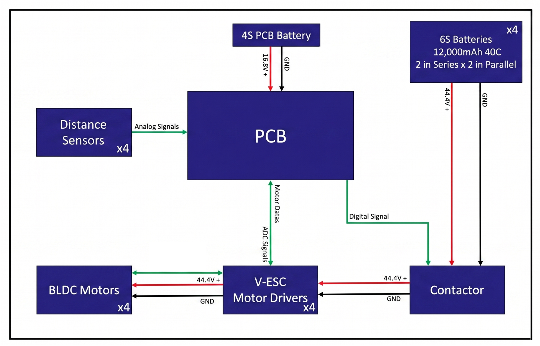
This architecture ensures a clear separation between power and control domains while maintaining tight integration through well-defined signal interfaces, enabling robust operation and future implementation of advanced control strategies. The system-level signal architecture is illustrated in Figure 9.

3.4. System-Level Integration and Design Rationale

The demonstrator is classified as self-contained, as all critical subsystems—including energy storage, actuation, sensing, and control—are fully integrated within the levitated structure. Unlike conventional laboratory test rigs that rely on external power supplies and instrumentation, the proposed architecture inherently incorporates onboard mass, coupling effects, and operational constraints representative of a realistic system.
This system-level integration is particularly critical prior to fully unconstrained multi-DoF validation. In the present study, the experimental configuration was constrained by mechanically restricting translational motion in the lateral and longitudinal directions, while allowing vertical motion. This constraint was primarily imposed by the physical limitations of the available conductive track, which does not provide sufficient length and width to safely accommodate fully unconstrained motion. As a result, the demonstrator was guided to remain aligned with the track, enabling stable positioning above the conductive plate while allowing controlled evaluation of load-carrying capability and air-gap behavior.
From a system integration perspective, the proposed architecture represents a tightly coupled multi-domain system. The mechanical structure ensures rigidity and geometric alignment, the actuation system generates the required electromagnetic excitation, the power system delivers high-current energy under controlled conditions, and the embedded electronics enable sensing, monitoring, and future control implementation.
This unified architecture establishes a scalable experimental platform, bridging the gap between simplified laboratory testbeds and integrated EDS systems by enabling evaluation under realistic onboard mass and power constraints.

4. Experimental Methodology

4.1. Constrained Test Configuration

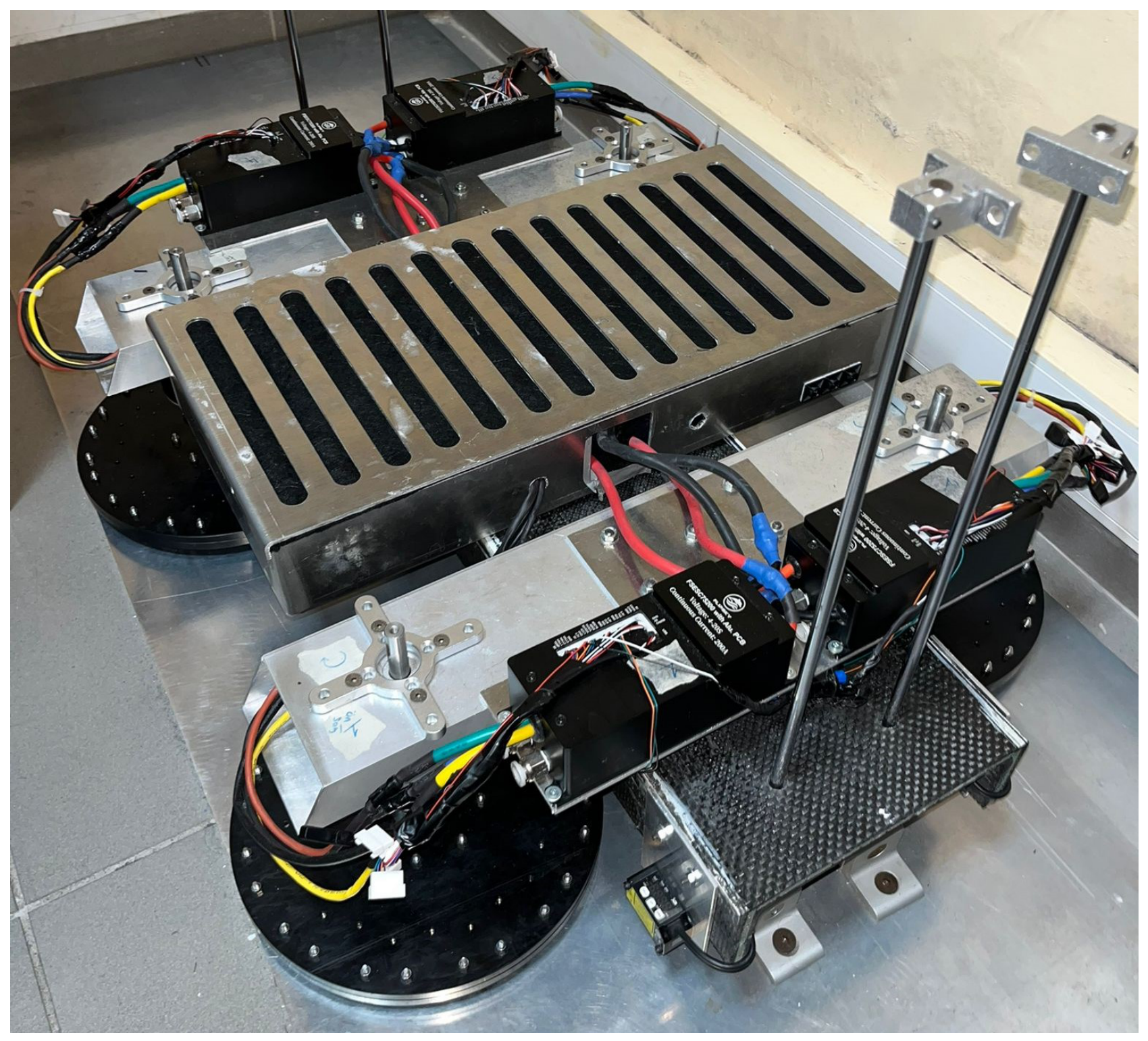
To experimentally evaluate the levitation behavior of the proposed platform under controlled and repeatable conditions, a constrained test configuration was established. In this setup, the demonstrator was mechanically guided to remain aligned with the conductive track by restricting translational motion in the lateral and longitudinal directions. This configuration enabled controlled evaluation of load-carrying capability and air-gap behavior under repeatable conditions. The assembled experimental setup used for the constrained levitation tests is shown in Figure 10.
The vertical guidance mechanism was implemented using aluminum sigma profiles positioned at the longitudinal ends of the structure and connected through rigid brackets. In addition, custom spacers were used to define the initial resting position of the platform and to maintain a minimum clearance of 10 mm from the conductive plate under zero-power conditions. This initial spacing also ensured repeatable release conditions for all experiments. The total mass of the assembled demonstrator used in the tests was approximately 35 kg.
All experiments were conducted on the same laboratory-scale conductive track described in the previous sections. The rotational speeds of the four motor-disk units were commanded through a MATLAB/Simulink (R2022b) interface, while the air-gap response was recorded simultaneously through the onboard sensing system. Under this arrangement, the experimental platform behaved as a vertically constrained levitation system, allowing direct observation of equilibrium air-gap formation, transient vertical response, and loss-of-levitation conditions.

4.2. Indirect Evaluation of Levitation Capability via Payload Testing

The levitation capability of the demonstrator was assessed indirectly by means of payload-based experiments. Rather than measuring the electromagnetic lift force directly, the system performance was evaluated by determining the maximum external load that could be sustained while maintaining non-contact levitation.
At the beginning of each test, the platform was positioned on the mechanical spacers corresponding to the initial 10 mm clearance. The rotating units were then accelerated to the target speed before the levitation response was evaluated. This procedure was adopted to reduce the influence of transient startup effects associated with rotor inertia and peak magnetic drag during the lift-off phase. Once the commanded speed was reached, the constrained platform was allowed to establish its levitation equilibrium.
Payload masses were then added incrementally to the structure using calibrated weights. The loading sequence was applied in 10 kg steps, followed by a final 7.5 kg increment near the operating limit. After each loading step, the air gap was continuously monitored until a steady response was achieved. The maximum payload capacity was defined as the highest load for which the system remained in stable non-contact levitation without triggering motor protection or experiencing rotor stall.
Because the applied masses were known a priori, no external force transducer was required in this procedure. The payload test therefore provided a system-level evaluation of levitation capability that inherently included the combined effects of electromagnetic force generation, onboard mass, structural response, and actuator power limitations.

4.3. Air-Gap Stability and Deviation Measurement Procedure

In addition to payload capacity, the operational stability of the demonstrator was evaluated through air-gap deviation measurements under steady-state levitation conditions. These experiments were performed using an open-loop speed command strategy in order to quantify the intrinsic vertical stability of the self-contained system without active feedback compensation.
For each test condition, a target rotational speed was assigned based on an experimentally obtained look-up relation between rotor speed and equilibrium air gap. After the platform was released from its initial resting position, the system was allowed to converge to a steady levitation state. Air-gap measurements were then recorded over a fixed time window while the platform mass and motor-speed command were kept constant.
As summarized in Table 5, the deviation analysis was conducted for reference air-gap conditions of 14.75, 15.00, 15.25, 15.50, and 15.75 mm. The acceptable air-gap deviation was defined as ±0.5 mm, as specified in Table 1. The recorded dataset consisted of 1435 samples in total. From these measurements, the steady-state deviation characteristics were quantified statistically in terms of spread around the equilibrium position. This procedure enabled direct evaluation of the repeatability and stability of the levitation response under different operating points.
The same measurement framework was also used to examine whether the experimentally achieved air-gap values remained within the practically acceptable deviation range defined for the demonstrator. In this way, the methodology provided a consistent basis for comparing payload-dependent levitation behavior and steady-state stability characteristics within the same constrained test environment.

5. Results and Discussion

5.1. Maximum Payload Capacity and System Limitations

The levitation capability of the proposed demonstrator was evaluated through incremental payload testing. The baseline system, with a total mass of approximately 35 kg, achieved stable levitation prior to the addition of external loads.
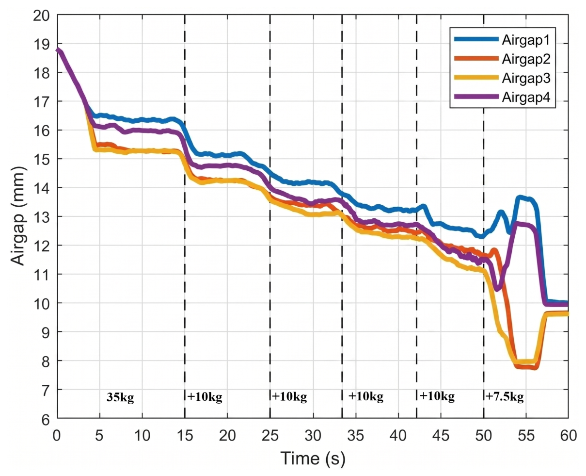
External payloads were introduced in discrete increments of 10 kg (10, 20, 30, and 40 kg), followed by a final 7.5 kg increment near the operational limit, corresponding to a maximum external payload of 47.5 kg. Considering the baseline demonstrator mass of approximately 35 kg, the total system mass reached approximately 82.5 kg under the final loading condition prior to the loss of levitation. The payload additions were applied sequentially during the experiment, and the corresponding loading stages can be identified from the transient air-gap response shown in Figure 11. As the applied mass increased, a progressive reduction in the levitation air gap was observed, indicating the increasing electromagnetic force demand required to balance the system weight. Despite this reduction in air gap, stable levitation was maintained throughout all intermediate loading stages.
The transient air-gap response during the loading sequence is presented in Figure 11. A clear asymmetry between the sensor measurements is observed, where sensors 2 and 3 consistently report lower air-gap values compared to sensors 1 and 4. This behavior indicates a non-uniform load distribution caused by an offset in the center of gravity, resulting in an inclined levitation posture. As a result, disks 2 and 3 were subjected to a higher effective load compared to disks 1 and 4, leading to increased torque demand and earlier saturation of the corresponding drive units.
The critical operating limit was reached at approximately 50 s, upon the addition of the final 7.5 kg payload. At this point, the motors associated with disks 2 and 3 reached their effective torque and current limits, leading to actuator saturation and triggering the protection mechanisms of the motor drivers. Following this event, a rapid decrease in air-gap values was recorded for sensors 2 and 3, while sensors 1 and 4 exhibited a temporary increase due to load redistribution. Subsequently, the system lost levitation and descended onto the predefined mechanical spacers.
Although direct electrical current and voltage telemetry were not recorded during the experiments, the observed behavior is consistent with the expected increase in current demand due to elevated magnetic drag forces at reduced air gaps. Therefore, the electrical power characteristics of the system were evaluated primarily through theoretical power analysis and experimentally observed actuator saturation behavior under increasing payload conditions. This behavior demonstrates that the maximum payload capacity of the system is not limited by the fundamental electrodynamic levitation mechanism, but rather by the available actuation power and current limits of the onboard drive system. In this context, the observed stall condition represents a system-level operational boundary. This finding highlights a key distinction between externally powered laboratory setups and fully self-contained EDS systems, where power delivery and actuator constraints become the dominant factors governing system performance.

5.2. Levitation Stability and Air-Gap Deviation Characteristics

The measured steady-state response of the levitation system was analyzed at five predefined reference air-gap conditions, as listed in Table 5. For each operating point, the system was allowed to reach equilibrium, and air-gap measurements were recorded over a fixed sampling window.
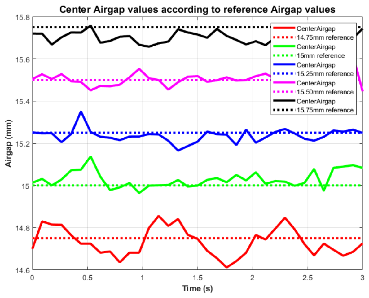
The measured air-gap values at each reference condition are compared against their corresponding targets in Figure 12. The experimental results demonstrate a close agreement between the commanded and achieved air-gap values, indicating the consistency of the open-loop operating strategy.
The statistical characteristics of the steady-state air-gap measurements are summarized in Table 6. For all reference conditions, the system exhibited low standard deviation values, indicating a stable levitation response with minimal fluctuation around the equilibrium position.
Across all operating conditions, the deviation of the air gap remained within a narrow band of approximately ±0.1 mm. This level of stability is significantly below the predefined acceptable limit of ±0.5 mm, indicating a robust steady-state response.
The observed deviations are primarily attributed to sensor noise, vibrations induced by the rotating disks, and minor structural compliance within the system. Accordingly, the measured air-gap fluctuations are interpreted as secondary mechanical and measurement-related effects rather than indicators of inherent electromagnetic instability.

5.3. Engineering Insights and System-Level Implications

The experimental results highlight the strong coupling between mechanical loading, electromagnetic force generation, and actuation system limitations in the proposed self-contained architecture. As the payload increases, the required levitation force rises, leading to a reduction in the achievable air gap at constant rotational speeds. This, in turn, increases the induced eddy currents and associated magnetic drag forces, directly translating into higher torque demand and current draw from the drive system.
A key finding of this study is that the operational boundary of the self-contained EDS demonstrator is governed primarily by actuator current and power limitations rather than by electromagnetic levitation capability. Although the levitation force can be increased by reducing the air gap, this approach rapidly increases magnetic drag and torque requirements, making it impractical due to actuator constraints.
Furthermore, the experiments revealed a strong sensitivity to mass distribution within the platform. Even minor offsets in the center of gravity resulted in uneven load sharing among the levitation units, leading to asymmetric air-gap behavior and localized overloading of specific motors, as smaller air gaps locally increase magnetic drag and current demand. This highlights the importance of precise mass balancing in multi-actuator EDS systems. While such asymmetries can be compensated by differential speed control of individual disks using the existing distance sensors and independent motor drives, all experiments in this study were conducted under equal-speed conditions, and therefore these effects were directly observed in the measured air-gap distribution.
In terms of operational limits, the duration of continuous levitation was primarily constrained by the available onboard energy capacity. The high current demand associated with elevated magnetic drag leads to significant power consumption, directly limiting the achievable operation time, while thermal effects remain secondary within the tested conditions. Although the system was originally designed based on a minimum operational requirement of 60 s, the selected battery configuration was intentionally oversized in order to avoid operation near the discharge limits of the batteries. Under full-power conditions, the onboard battery system is capable of supplying the demonstrator for approximately 145 s. Furthermore, the experimental tests conducted in this study were performed below the maximum continuous power level of the system; therefore, no operational time limitation was encountered during the experiments.
From a design perspective, electromagnetic optimization should not focus solely on maximizing levitation force. Increasing lift by reducing the air gap is straightforward; however, this simultaneously increases magnetic drag and torque demand. Therefore, minimizing drag force is equally critical, as it directly determines both the feasibility of achieving levitation and the sustainability of operation.
The practical implementation of Halbach arrays requires careful consideration of mechanical integration and material selection. Although theoretical configurations may suggest closely packed magnet arrangements, the strong interaction forces between magnets make assembly challenging. Adequate spacing, robust structural support, and appropriate disk material selection are essential to ensure safe operation. In addition, while non-conductive materials reduce parasitic eddy current losses, they must also allow for precise balancing, as imbalance-induced vibrations can lead to mechanical damage at high rotational speeds.
Another critical aspect is the transient torque requirement during startup. The torque required to accelerate the disk from rest in the presence of a conductive plate is significantly higher than the torque required during steady-state operation. As a result, systems that can sustain levitation at a given speed may still fail to reach that speed under load. This necessitates either controlled engagement strategies or careful motor sizing based on worst-case torque conditions.
Increasing actuator capability is also subject to a coupled design trade-off. Higher motor power requires larger motors, drivers, and energy storage systems, all of which increase system mass. This added mass increases the required levitation force and associated drag, reinforcing the need for a co-design approach between electromagnetic and actuation subsystems.
Mechanical stiffness plays a critical role in maintaining stable levitation. Structural deformation directly affects the air gap, and even small deflections can lead to significant performance degradation in systems operating at millimeter-scale tolerances. Ensuring high structural rigidity is therefore essential for consistent and repeatable operation; otherwise, similar experimental results cannot be reliably reproduced.
Thermal effects, particularly within the conductive plate, may become significant in prolonged operation scenarios due to eddy current losses. Although thermal behavior was not experimentally investigated in the present study, heat generation within the conductive plate could potentially lead to thermal expansion and air-gap deviations in long-duration applications, indicating the possible need for future thermal management considerations.
From a dynamic standpoint, the rotational inertia of the disks can introduce additional challenges during transient operation. The use of counter-rotating disks is recommended to reduce net angular momentum and improve system stability.
Finally, the presence of high currents and electromagnetic interference necessitates careful design of the sensing and communication infrastructure. Proper isolation and filtering of sensor signals are essential to ensure reliable measurement and control performance in such environments. In addition, the resolution of the position measurement sensors should be selected at least one order of magnitude (≈10×) higher than the target air-gap resolution; in this study, a sensor resolution of 30 μ m was used for an air-gap deviation range on the order of 0.5 mm .
Discrepancies between simulation and experimental results were also observed. Finite element predictions of levitation force did not fully match experimental measurements, likely due to edge effects, skin effects, and modeling limitations. Consequently, a conservative safety factor on the order of 2 is recommended when designing electromagnetic systems and selecting actuators.
Moreover, the motor controllers were configured to limit current below their theoretical maximum ratings for safety reasons. As a result, the experimentally validated payload capacity represents a conservative operational limit rather than the absolute physical capability of the system.
Overall, these findings demonstrate that the performance of self-contained EDS systems is governed by tightly coupled electromagnetic, mechanical, and actuation constraints, requiring a holistic design approach that considers force generation, drag minimization, actuator capability, structural integrity, and energy consumption.


6. Conclusions

This study presented the design and experimental validation of a fully self-contained electrodynamic suspension (EDS) demonstrator based on rotating Halbach arrays. In contrast to conventional laboratory-scale setups, the proposed system integrates energy storage, actuation, sensing, and control subsystems within a single levitating platform, enabling the evaluation of EDS behavior under onboard mass and power constraints. The experimental results demonstrated stable levitation of a 35 kg baseline platform with additional payloads approaching twice the baseline mass, while maintaining air-gap deviations within approximately ±0.1 mm, significantly below the predefined limit of ±0.5 mm. The results indicate that the practical operating limit of the system is primarily determined by actuator capability rather than electromagnetic levitation performance, since increased payload leads to higher drag-induced torque and current demand. In addition, sensitivity to center-of-gravity offsets was observed to influence load distribution among the levitation units, highlighting the importance of mass balancing in multi-actuator EDS platforms.
The experimental findings show that the performance of self-contained EDS systems depends not only on levitation force generation but also on the interaction between electromagnetic, mechanical, and actuation subsystems. The constrained test configuration provided a controlled environment for investigating these effects while ensuring safe operation throughout the experiments. The developed platform establishes an experimental basis for future studies on multi-degree-of-freedom operation, active stabilization methods, reduced-order modeling, and data-driven system identification. Further improvements in lift-to-drag ratio and overall system efficiency are expected to play an important role in extending the operating capabilities of self-contained EDS systems.

Author Contributions

Conceptualization, H.G. and M.G.; methodology, H.G.; software, H.G.; validation, H.G.; formal analysis, H.G.; investigation, H.G.; resources, H.G.; data curation, H.G.; writing—original draft preparation, H.G.; writing—review and editing, H.G. and M.G.; visualization, H.G.; supervision, M.G.; project administration, M.G. All authors have read and agreed to the published version of the manuscript.

Funding

This research received no external funding.

Institutional Review Board Statement

Not applicable.

Informed Consent Statement

Not applicable.

Data Availability Statement

The data presented in this study are available from the corresponding author upon reasonable request.

Acknowledgments

The authors would like to thank STARLOOP Laboratory for providing technical infrastructure and experimental support during the development of the prototype. The authors also acknowledge Neslihan Üst, Ferhat Rudvanoğulları, Erhan Birer, Furkan İlbeyi, and Erenalp Çakıroğlu for their valuable assistance during the experimental and assembly phases of the study. Valuable technical discussions and guidance provided by Abdurrahman Yilmaz during the preparation of the manuscript are gratefully acknowledged. The authors used artificial intelligence (AI)-assisted tools (chat GPT 5.5) solely for language refinement, grammar checking, and editorial support during manuscript preparation. All scientific content, analyses, interpretations, and conclusions were developed, verified, and approved by the authors.

Conflicts of Interest

The authors declare no conflicts of interest.

Abbreviations

The following abbreviations are used in this manuscript:
EDSElectrodynamic Suspension
EMSElectromagnetic Suspension
EDWElectrodynamic Wheel
FEMFinite Element Method
BLDCBrushless Direct Current
FOCField-Oriented Control
PWMPulse Width Modulation
VESCVedder Electronic Speed Controller
LCULevitation Control Unit
MCUMicrocontroller Unit
PCBPrinted Circuit Board
CNCComputer Numerical Control
CADComputer-Aided Design
DCDirect Current
Li-PoLithium Polymer
POMPolyoxymethylene (Delrin)
NdFeBNeodymium-Iron-Boron
DoFDegree of Freedom
rpmrevolutions per minute

References

  1. Song, M.; Zhou, D.; Yu, P.; Zhao, Y.; Wang, Y.; Tan, Y.; Li, J. Analytical calculation and experimental verification of superconducting electrodynamic suspension system using null-flux ground coils. IEEE Trans. Intell. Transp. Syst. 2021, 23, 14978–14989. [Google Scholar] [CrossRef] [Scilit]
  2. Han, H.S.; Kim, D.S. Magnetic levitation. In Springer Tracts on Transportation and Traffic; Springer: Dordrecht, The Netherlands, 2016; Volume 247. [Google Scholar]
  3. Nøland, J.K. Prospects and challenges of the hyperloop transportation system: A systematic technology review. IEEE Access 2021, 9, 28439–28458. [Google Scholar] [CrossRef] [Scilit]
  4. Wu, C.; Li, G.; Wang, D.; Xu, J. Dynamic characterization of permanent magnet electrodynamic suspension system with a novel passive damping magnet scheme. J. Sound Vib. 2025, 599, 118849. [Google Scholar] [CrossRef] [Scilit]
  5. Beauloye, L.; Dehez, B. Permanent magnet electrodynamic suspensions applied to MAGLEV transportation systems: A review. IEEE Trans. Transp. Electrif. 2022, 9, 748–758. [Google Scholar] [CrossRef] [Scilit]
  6. Rote, D.M.; Cai, Y. Review of dynamic stability of repulsive-force maglev suspension systems. IEEE Trans. Magn. 2002, 38, 1383–1390. [Google Scholar] [CrossRef] [Scilit]
  7. Shi, H.; Deng, Z.; Ke, Z.; Li, Z.; Zhang, W. Linear permanent magnet electrodynamic suspension system: Dynamic characteristics, magnetic-mechanical coupling and filed test. Measurement 2024, 225, 113960. [Google Scholar] [CrossRef] [Scilit]
  8. Post, R.F.; Ryutov, D.D. The Inductrack Approach to Magnetic Levitation; Technical Report; Lawrence Livermore National Lab.: Livermore, CA, USA, 2000.
  9. Reitz, J.R.; Davis, L. Force on a rectangular coil moving above a conducting slab. J. Appl. Phys. 1972, 43, 1547–1553. [Google Scholar] [CrossRef] [Scilit]
  10. Powell, J.; Danby, G. Magnetic suspension for levitated tracked vehicles. Cryogenics 1971, 11, 192–204. [Google Scholar] [CrossRef] [Scilit]
  11. Flankl, M.; Wellerdieck, T.; Tüysüz, A.; Kolar, J.W. Scaling laws for electrodynamic suspension in high-speedtransportation. IET Electr. Power Appl. 2018, 12, 357–364. [Google Scholar] [CrossRef] [Scilit]
  12. Kublin, T.; Grzesiak, L.; Góźdź, M. Experimental Validation of a Modified Halbach Array for Improved Electrodynamic Suspension Efficiency. Energies 2026, 19, 649. [Google Scholar] [CrossRef] [Scilit]
  13. Iniguez, J.; Raposo, V. Numerical simulation of a simple low-speed model for an electrodynamic levitation system based on a Halbach magnet array. J. Magn. Magn. Mater. 2010, 322, 1673–1676. [Google Scholar] [CrossRef] [Scilit]
  14. Paul, S.; Bird, J.Z. A 3-D analytic eddy current model for a finite width conductive plate. COMPEL Int. J. Comput. Math. Electr. Electron. Eng. 2013, 33, 688–706. [Google Scholar] [CrossRef] [Scilit]
  15. Miericke, J.; Urankar, L. Theory of electrodynamic levitation with a continuous sheet track—Part I. Appl. Phys. 1973, 2, 201–211. [Google Scholar] [CrossRef] [Scilit]
  16. Liu, J.; Cao, T.; Deng, Z.; Shi, H.; Liang, L.; Wu, X.; Jiang, S. Damping characteristics improvement of permanent magnet electrodynamic suspension by utilizing the end-effect of onboard magnets. Electr. Eng. 2024, 106, 15–29. [Google Scholar] [CrossRef] [Scilit]
  17. Zhu, P.; Li, J.; Chen, Q.; Tan, Y.; Liu, M.; Zhou, D. A suspension damping enhancement method based on permanent magnet damping conductive plate for superconducting Maglev sled. IEEE Trans. Magn. 2024, 61, 8000109. [Google Scholar] [CrossRef] [Scilit]
  18. Galluzzi, R.; Circosta, S.; Amati, N.; Tonoli, A.; Bonfitto, A.; Lembke, T.A.; Kertész, M. A multi-domain approach to the stabilization of electrodynamic levitation systems. J. Vib. Acoust. 2020, 142, 061004. [Google Scholar] [CrossRef] [Scilit]
  19. He, J.L.; Rote, D.M.; Coffey, H.T. Applications of the dynamic circuit theory to maglev suspension systems. IEEE Trans. Magn. 1993, 29, 4153–4164. [Google Scholar]
  20. Chu, D.; Moon, F.C. Dynamic instabilities in magnetically levitated models. J. Appl. Phys. 1983, 54, 1619–1625. [Google Scholar] [CrossRef] [Scilit]
  21. Liu, K.; Ma, G.; Luo, J.; Zhu, Z.; Li, J.; Su, Z.; Gong, T. Equivalent simulation and measurement for the electrodynamic suspension system based on the dynamic circuit theory. IEEE Trans. Instrum. Meas. 2024, 73, 7509715. [Google Scholar] [CrossRef] [Scilit]
  22. Lee, H.W.; Kim, K.C.; Lee, J. Review of maglev train technologies. IEEE Trans. Magn. 2006, 42, 1917–1925. [Google Scholar] [CrossRef] [Scilit]
  23. Cassat, A.; Jufer, M. MAGLEV projects technology aspects and choices. IEEE Trans. Appl. Supercond. 2002, 12, 915–925. [Google Scholar] [CrossRef] [Scilit]
  24. Zhang, S.; Wu, S.; Shi, H.; Li, Z.; Deng, Z. A Novel Overlapped Compensation Structure and Its Effectiveness Verification for Expansion Joints in Plate-Type PMEDS Vehicles. Actuators 2025, 14, 182. [Google Scholar] [CrossRef] [Scilit]
  25. Qin, W.; Ma, Y.; Lv, G.; Wang, F.; Zhao, J. New levitation scheme with traveling magnetic electromagnetic Halbach array for EDS maglev system. IEEE Trans. Magn. 2021, 58, 8300106. [Google Scholar] [CrossRef] [Scilit]
  26. Duan, J.; Xiao, S.; Zhang, K.; Rotaru, M.; Sykulski, J. Analysis and optimization of asymmetrical double-sided electrodynamic suspension devices. IEEE Trans. Magn. 2019, 55, 8300605. [Google Scholar] [CrossRef] [Scilit]
  27. Halbach, K. Design of permanent multipole magnets with oriented rare earth cobalt material. Nucl. Instrum. Methods 1980, 169, 1–10. [Google Scholar] [CrossRef] [Scilit]
  28. Zhu, Z.; Howe, D. Halbach permanent magnet machines and applications: A review. IEE Proc.-Electr. Power Appl. 2001, 148, 299–308. [Google Scholar] [CrossRef] [Scilit]
  29. Han, Q. Analysis and Modeling of the EDS Maglev System Based on the Halbach Permanent Magnet Array. Ph.D. Thesis, University of Central Florida, Orlando, FL, USA, 2004. [Google Scholar]
  30. Hu, Y.; Long, Z.; Zeng, J.; Wang, Z. Analytical optimization of electrodynamic suspension for ultrahigh-speed ground transportation. IEEE Trans. Magn. 2021, 57, 8000511. [Google Scholar] [CrossRef] [Scilit]
  31. Jiangbo, W.; Chunsheng, L.; Wei, X.; Baofeng, Y. Optimization design of linear Halbach array for EDS maglev. In Proceedings of the 2008 IEEE Vehicle Power and Propulsion Conference; IEEE: Piscataway, NJ, USA, 2008; pp. 1–5. [Google Scholar]
  32. Ham, C.; Ko, W.; Han, Q. Analysis and optimization of a Maglev system based on the Halbach magnet arrays. J. Appl. Phys. 2006, 99, 08P510. [Google Scholar] [CrossRef] [Scilit]
  33. Choi, J.S.; Yoo, J. Design of a Halbach magnet array based on optimization techniques. IEEE Trans. Magn. 2008, 44, 2361–2366. [Google Scholar] [CrossRef] [Scilit]
  34. Hasanzadeh, S.; Rezaei, H.; Qiyassi, E. Analysis and optimization of permanent magnet dimensions in electrodynamic suspension systems. J. Electr. Eng. Technol. 2018, 13, 307–314. [Google Scholar]
  35. Huang, H.; Cheng, Y.; Li, H.; Li, H.; Deng, Z.; Zheng, J.; Lin, G. Experimental Platform Design and Transient Guidance Force Analysis for Null-Flux Coil Type Electrodynamic Suspension System. IEEE Trans. Energy Convers. 2025, 41, 1209–1221. [Google Scholar] [CrossRef] [Scilit]
  36. Mollahasanoglu, H.; Abdioglu, M.; Ozturk, U.K.; Okumus, H.I. Experimental investigation of magnetic forces in PMA and HTS configurations using a high-speed electrodynamic levitation test system. Measurement 2025, 262, 120092. [Google Scholar] [CrossRef] [Scilit]
  37. Abdullah, S.H.; Mohiuddin, M.S.; Hasnain, M.; Siddiq, M.I.; Aziz, M.A. Experimental Study on Performance Characteristics of Electrodynamic Rotors in Maglev Transportation System. Int. J. New Technol. Res. 2019, 5, 44–48. [Google Scholar] [CrossRef] [Scilit]
  38. Ma, G.; Wang, Y.; Luo, J.; Cai, Y.; Wang, R.; Song, X. An analytical-experiment coupling method to characterize the electrodynamic suspension system at various speeds. IEEE Trans. Ind. Electron. 2021, 69, 7170–7180. [Google Scholar] [CrossRef] [Scilit]
  39. Gurol, H.; Baldi, R.; Jeter, P.; Kim, I.-K.; Bever, D. General Atomics Low Speed Maglev Technology Development Program (Supplemental #3); U.S. Department of Transportation, Federal Transit Administration, Office of Technology: Washington, DC, USA, 2005.
  40. Jia, Z.; Tan, Y.; Li, J.; Zhou, D.; Leng, P.; Chen, Q. Active Guidance Control of the Electromagnetic Propulsion and Electrodynamic Suspension Combined System. IEEE Trans. Appl. Supercond. 2024, 34, 3603112. [Google Scholar] [CrossRef] [Scilit]
  41. Paudel, N.; Bird, J.Z. Modeling the dynamic electromechanical suspension behavior of an electrodynamic eddy current maglev device. Prog. Electromagn. Res. B 2013, 49, 1–30. [Google Scholar] [CrossRef] [Scilit]
  42. Tonoli, A.; Amati, N. Dynamic modeling and experimental validation of eddy current dampers and couplers. J. Vib. Acoust. 2008, 130, 021011. [Google Scholar] [CrossRef] [Scilit]
  43. Bird, J.; Lipo, T. A preliminary investigation of an electrodynamic wheel for simultaneously creating levitation and propulsion. In Proceedings of the 18th International Conference on Magnetically Levitated Systems and Linear Drives, Shanghai, China, 26–28 October 2004; pp. 316–325. [Google Scholar]
  44. Chen, Y.; Zhang, W.; Bird, J.Z.; Paul, S.; Zhang, K. A 3-D analytic-based model of a null-flux Halbach array electrodynamic suspension device. IEEE Trans. Magn. 2015, 51, 8300405. [Google Scholar] [CrossRef] [Scilit]
  45. Halbach, K. Application of permanent magnets in accelerators and electron storage rings. J. Appl. Phys. 1985, 57, 3605–3608. [Google Scholar] [CrossRef] [Scilit]
  46. Post, R.F. Inductrack Demonstration Model; Technical Report; Lawrence Livermore National Lab. (LLNL): Livermore, CA, USA, 1998.
  47. Post, R.F.; Ryutov, D.D. The inductrack: A simpler approach to magnetic levitation. IEEE Trans. Appl. Supercond. 2002, 10, 901–904. [Google Scholar] [CrossRef] [Scilit]
Figure 1. General geometry of the circular Halbach array and corresponding magnetic field distribution showing unilateral flux concentration. The arrows indicate the in-plane magnetization directions of the permanent magnets, while the symbols “X” and “O” represent magnetic field directions into and out of the page, respectively.
Asi 09 00128 g001
Figure 2. Selected circular Halbach array configuration and corresponding magnetic field distribution, demonstrating flux concentration on the active side and field cancellation on the opposite side. The arrows indicate the magnetization directions of the permanent magnets, while the symbols “X” and “O” represent magnetic field directions into and out of the page, respectively.
Asi 09 00128 g002
Figure 3. Magnetic field vector distribution of the selected circular Halbach array, illustrating strong flux concentration on the active side and field cancellation on the opposite side. The simulation results indicate magnetic flux densities of approximately 1.2 T on the active side and 0.4 T on the passive side.
Asi 09 00128 g003
Figure 4. Electromagnetic performance of the selected Halbach array under identical operating conditions (1000 rpm, 5 mm air gap, 12.7 mm Al6101-T6 conductive plate). The configuration provides sufficient levitation force with acceptable magnetic drag torque, forming the basis of the final system design.
Asi 09 00128 g004
Figure 5. Variation of levitation force and magnetic drag torque as functions of rotational speed (RPM) and air gap for the selected Halbach array. The simulation results illustrate the nonlinear behavior of the EDS system and define the practical operating envelope.
Asi 09 00128 g005
Figure 6. Three-dimensional CAD visualization of the complete levitation platform, illustrating the spatial arrangement of the Halbach rotors, motor assemblies, composite chassis, and auxiliary subsystems.
Asi 09 00128 g006
Figure 7. Finite element analysis of the composite chassis under representative lift and structural loads. (a) Equivalent stress distribution. (b) Total deformation. The simulation results demonstrate high global stiffness and elastic behavior under operational conditions, with negligible structural deformation.
Asi 09 00128 g007
Figure 8. Finite element results of the EDS rotor disk under combined lift, centrifugal, and torque loads. (a) Equivalent stress distribution. (b) Total deformation. The simulation results confirm structurally safe operation with limited elastic deformation under peak rotational loading conditions.
Asi 09 00128 g008
Figure 9. Block diagram of the electronic control and power architecture of the proposed EDS platform. The PCB-based levitation control unit receives analog air-gap signals from four distance sensors and generates digital control commands for the VESC motor drivers. The propulsion subsystem is powered by a 12S Li-Po battery pack through a high-current contactor, while low-voltage control electronics are supplied by an isolated 4S battery.
Asi 09 00128 g009
Figure 10. Assembled experimental setup used for payload and levitation deviation tests.
Asi 09 00128 g010
Figure 11. Filtered air-gap measurements from four sensors during payload testing. Sensors 2 and 3 exhibit lower values due to center-of-gravity offset. The payload was increased sequentially during the experiment from 0 kg to 47.5 kg external load in discrete loading steps.
Asi 09 00128 g011
Figure 12. Comparison of measured center air-gap values with corresponding reference targets across five operating conditions.
Asi 09 00128 g012
Table 1. Requirement specifications for the Halbach-array levitation system.
ParameterValue
Mass of the system80 kg
Thickness of conductive plate12.7 mm
Plate width600 mm
Plate length2000 mm
Plate materialAl6101-T6
Operation duration (nominal)60 s
Air-gap stability (design requirement)±0.5 mm
Table 2. Selected Halbach array design parameters.
ParameterValue
Number of magnet types2
Number of magnets24
Dimensions of magnet 160 × 20 × 10 mm
Dimensions of magnet 240 × 10 × 10 mm
Arrangement of the magnets90° Halbach
Inner diameter of the magnets120 mm
Outer diameter of the magnets240 mm
Minimum distance between magnets4.5 mm
Table 3. Summary of key mechanical components and material selection of the demonstrator.
SubsystemMaterialEngineering Role
EDS Disks (Upper/Lower)POM DelrinNon-magnetic structure with high stiffness under centrifugal loading
ChassisCarbon fiber compositeLightweight rigid backbone ensuring structural integrity
Motor MountsAl7075High-strength connection maintaining alignment under load
Sensor MountsAl7075Precision positioning for accurate air-gap measurement
Battery EnclosureAl7075Structural housing and mass integration of onboard energy system
Support ProfilesAl7075Load distribution and mechanical reinforcement
Conductive TrackAl6101-T6High-conductivity surface for eddy current generation
Table 4. Summary of the onboard actuation and control system components.
SubsystemComponentEngineering Role
ActuationFlipsky BLDC 80100 (130 kV)High-torque, low-friction rotation of Halbach disks
Motor ControlFlipsky 75200 VESC (FOC)Precise speed/torque control with high-current capability
Main Power Supply12S Li-Po Battery PackHigh-current energy source for simultaneous multi-motor operation
Control Power Supply4S Li-Po BatteryElectrical isolation of low-voltage control electronics
Control UnitSTM32H743ZI2 MCUReal-time processing and control algorithm implementation
SensingHG-C 1050-P Laser SensorsHigh-resolution air-gap measurement for levitation monitoring
Power ProtectionIK-EVQ300 ContactorSystem-level protection against overcurrent and fault conditions
Voltage RegulationLM2596 ConverterStable DC supply for control electronics
Table 5. Reference air-gap values and corresponding rotational speeds used in stability experiments.
#Reference Air Gap (mm)Rotational Speed (rpm)
1 14.75 ± 0.05 3289
2 15.00 ± 0.05 3636
3 15.25 ± 0.05 4156
4 15.50 ± 0.05 4791
5 15.75 ± 0.05 5483
Table 6. Statistical summary of steady-state air-gap measurements at different reference conditions.
Reference (mm)Mean (mm)Std (mm)Min (mm)Max (mm)
14.7514.7360.06514.61114.855
15.0015.0250.03714.96415.137
15.2515.2340.03115.16515.350
15.5015.5040.03215.44615.617
15.7515.7090.03815.62815.822
Disclaimer/Publisher’s Note: The statements, opinions and data contained in all publications are solely those of the individual author(s) and contributor(s) and not of MDPI and/or the editor(s). MDPI and/or the editor(s) disclaim responsibility for any injury to people or property resulting from any ideas, methods, instructions or products referred to in the content.