Article

Enhancing Axial Flow in Hydrokinetic Turbines via Multi-Slot Diffuser Design: A Computational Study

by
Daniel Sanin-Villa
1,*,†,
Jorge Sierra-Del Rio
2,
Diego Hincapié Zuluaga
3 and
Steven Galvis-Holguin
3,4,†
1
Área de Industria, Materiales y Energía, Universidad EAFIT, Medellín 050022, Colombia
2
Department of Mechanical, GIIAM, Faculty of Engineering, Institución Universitaria Pascual Bravo, Medellín 050036, Colombia
3
Department of Mechatronics, Faculty of Engineering, Instituto Tecnológico Metropolitano, Medellín 050034, Colombia
4
Department of Mechatronics, Faculty of Engineering, Escuela Colombiana de Carreras Industriales-ECCI, Medellín 050016, Colombia
*
Author to whom correspondence should be addressed.
These authors contributed equally to this work.
Appl. Syst. Innov. 2025, 8(5), 129; https://doi.org/10.3390/asi8050129
Submission received: 7 June 2025 / Revised: 8 August 2025 / Accepted: 7 September 2025 / Published: 11 September 2025

Abstract

Straight-walled diffusers can boost the power density of horizontal-axis hydrokinetic turbines (HKTs), but are prone to boundary layer separation when the divergence angle is too large. We perform a systematic factorial study of three diffuser configurations, slotless, mid-length single-slot, and outlet-slot with dual divergence angles, using a two-dimensional, transient SST k ω Reynolds-averaged Navier–Stokes model validated against wind tunnel data (maximum error 6.4%). Eight geometries per configuration are generated through a 2 3 Design of Experiments with variation in the divergence angle, flange or slot position, and inlet section. The optimal outlet-slot design re-energises the boundary layer, shortens the recirculation zone by more than 50%, and raises the mean axial velocity along the diffuser centreline by 12.6% compared with an equally compact slotless diffuser, and by 42.6% relative to an open flow without a diffuser. Parametric analysis shows that the slot position in the radial (Y) direction and the first divergence angle have the strongest influence on velocity augmentation. In contrast, the flange angle and axial slot location (X) are second-order effects. The results provide fabrication-friendly guidelines, restricted to straight walls and a single slot, that are capable of improving HKT performance in shallow or remote waterways where complex curved diffusers are impractical. The study also identifies key geometric and turbulence model sensitivities that should be addressed in future three-dimensional and multi-slot investigations.

1. Introduction

Sustainable development demands reliable access to low-cost energy resources that minimise social and environmental impacts [1]. Without significant policy shifts, global primary energy demand is projected to rise by 55% between 2005 and 2030, with developing regions relying on fossil fuels for 84% of supply and a consequent 57% increase in greenhouse gas emissions [2]. Accordingly, coal, oil, and natural gas fail to meet long-term sustainability criteria, whereas solar, wind, and hydroelectric sources offer enduring alternatives [3]. Access to electricity underpins socioeconomic advancement and enhances living standards; hence, small-scale hydroelectric plants represent an effective way to deploy energy in remote, water-rich areas [4]. Horizontal-axis hydrokinetic turbines (HKTs) exploit river currents without damming or diverting the flow, which imposes lower ecosystem disturbance compared with Pelton, Francis, or Kaplan turbines. However, HKTs currently achieve peak efficiencies near 30%, whereas the efficiency of Pelton designs can reach 90% [5,6,7].
Several key design parameters influence the enhancement of HKTs. Improvements in rotor architecture [8,9,10], blade geometry [11,12], and operational alignment [13] all contribute to performance gains. Comparable CFD analyses performed for Pelton injectors show that modest geometric changes, such as a 75° needle-tip angle, can raise jet efficiency from 94% to 96%, showing how sensitive hydroturbine performance is to small design parameters [14]. Recent CFD work on gravitational-vortex concepts has also shown that rotor choice strongly affects energy capture [15], while an H-Darrieus rotor proved more efficient than the conventional Archimedes screw in the same basin geometry [16]. Nevertheless, modifications to these parameters alone cannot surpass the 59.3% Betz limit for energy extraction from a free stream [17,18]. To overcome this barrier, augmented diffusers create downstream low-pressure regions that boost mass flow and velocity through the turbine [19,20,21], thereby reducing flow misalignment and stagnation-pressure losses and enhancing overall efficiency [22].
Investigations of HKTs equipped with augmented diffusers have demonstrated substantial gains. Mehmood et al. employed a NACA 0018 diffuser for marine currents and, using CFD, obtained up to two-fold velocity increases [23]. Tampier et al. compared bare and diffuser-augmented turbines, recording a 39.4% efficiency gain and underscoring the need for co-design of turbines and diffusers [24]. Song et al. confirmed that a parallel design approach adapts turbine geometry to accelerated-flow conditions [25]. Vaz and Wood refined HKT blade aerodynamics based on diffuser acceleration ratios, achieving a power coefficient of 0.607, thereby surpassing the Betz limit [26]. Park et al. presented an optimised 5 kW ducted hydrokinetic turbine that attains up to 50% efficiency under practical constraints [27]. Vaz et al. carried out a numerical study of a conical-diffuser HKT, reporting a 55% increase in the power coefficient at a tip-speed ratio of 5.4, equivalent to a 1.5-fold rise in generated power [28]. Similarly, Ng et al. determined the geometric effect of augmented diffusers via CFD, showing that curved diffusers outperform flat ones with average gains of 2.2% in C p and 4% in C t relative to undiffused cases [29].
State-of-the-art diffuser designs fall into three categories: convergent–divergent profiles (first generation), straight-walled sections with flanges (second generation), and multi-slot diffusers (third generation). Convergent–divergent shapes yield significant performance improvements, but require complex fabrication; straight-walled diffusers simplify production, yet suffer separation at large divergence angles; and multi-slot designs energise the boundary layer through injected flow, mitigating separation, although their use in hydrokinetic applications remains limited [19].
This study investigates the influence of straight-walled, slotless, and single-slot diffuser geometries on internal velocity profiles to increase the available kinetic energy for HKTs. Three configurations are analysed using three experimental designs: a slotless design and two single-slot variants. Computational simulations quantify velocity augmentation and inform design guidelines for diffuser-augmented hydrokinetic systems.
The present study extends current knowledge by (i) providing a systematic parametric comparison of straight-walled, slotless, and single-slot diffusers normalised by rotor diameter; (ii) quantifying how the slot location and divergence angle jointly influence boundary layer re-energisation and pressure recovery; and (iii) identifying a geometric regime that raises the mean axial velocity by 12.6% relative to a slotless diffuser design while markedly suppressing separation. From an industrial standpoint, the findings provide fabrication-friendly design guidelines for low-head, low-maintenance HKTs suitable for isolated communities, thereby reducing the levelised cost of electricity and simplifying field installation.
Section 2 details the diffuser parameterisation, the experimental designs proposed, the numerical model, and the mesh-convergence protocol. Section 3 validates the computational framework against benchmark data and presents velocity and pressure fields for the three diffuser geometries seleted. Section 4 discusses the implications for turbine design, operational reliability, and future optimisation strategies. Finally, Section 5 summarises the principal findings, outlines limitations, and proposes avenues for experimental and three-dimensional extensions.

2. Methodology

The hydrokinetic turbine (HKT) extracts kinetic energy from a water current impinging perpendicular to its rotor axis, converting it into mechanical torque and rotational power [30]. As shown in Figure 1, flow deceleration occurs as energy transfers to the blades, causing the spacing of streamlines to increase downstream under constant mass flow conditions.
Under steady inflow, the instantaneous power output P of an HKT is given by
P = 1 2 ρ U 3 A r C p η ,
where ρ is the water density, U is the free-stream velocity, A r is the swept rotor area, C p is the power coefficient, and η is the overall mechanical–electrical efficiency. The coefficient C p represents the fraction of the available kinetic power that the turbine captures:
C p = P 1 2 ρ U 3 A r η .
In this study, all the dimensions of the diffuser are normalised concerning the rotor diameter D (1512 mm) to ensure scalability across different HKT sizes. However, the presence of the HKT itself is not considered in this analysis.

2.1. Diffuser Geometry and Experimental Designs

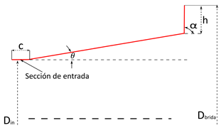
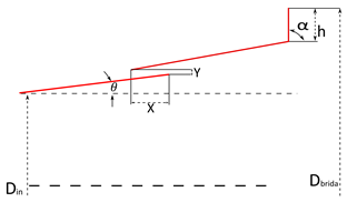
The diffuser-augmented configurations studied here were defined after an extensive survey of the literature on both hydrokinetic and wind turbine diffuser designs [19,21,24]. Twelve geometric parameters were identified as most influential on axial acceleration and boundary layer behaviour (Table 1). Convergent–divergent profiles were excluded to focus on straight-walled diffusers that are simpler to manufacture and assemble.
To isolate the effects of slot geometry and divergence angles on the internal flow, only c, α , θ , β , and the slot coordinates (X, Y) were varied. All other dimensions ( D in , D flange , L t , Δ r , h) were held constant across configurations. Normalising each length by the rotor diameter D ensures scalability to different HKT sizes.
Three diffuser variants were modelled
  • Diffuser 1: Straight-walled slotless design (Silva et al. methodology [21]).
  • Diffuser 2: Straight-walled with a single slot.
  • Diffuser 3: Straight-walled with a single slot and two divergence angles.
Taking the above into account, a 2 3 factorial Design of Experiments (DOE) was implemented for each augmented diffuser using Minitab v18 software. Each DOE considered three factors, each evaluated at two levels. As a result, each experimental design comprised eight distinct geometries, enabling a quantitative assessment of the geometric parameters with the greatest influence on the average axial velocity within the augmented diffuser.
DOE 1 investigates the effects of the divergence angle ( θ ), flange angle ( α ), and inlet section (c). DOE 2 focuses on the position of the slot (X and Y) and also includes the divergence angle ( θ ), since it was identified in DOE 1 as the parameter with the greatest influence on the response variable. Therefore, the divergence angle was kept at the same level to evaluate and compare the performance of the augmented diffuser with and without a slot, using identical divergence angles. In DOE 3, two divergence angles are proposed, each corresponding to a different section of the diffuser: the inlet section is defined by divergence angle θ , and the outlet section by divergence angle β . Additionally, only the slot position in the Y direction is considered, as DOE 2 revealed that the slot position in the X direction does not significantly affect the response variable.
The levels for each parameter were selected based on the values reported in the literature. However, none of the referenced studies combine the specific parameters and levels used in this work. Table 2 summarizes the information from the three DOEs, providing a clearer overview of the factors considered in this study.

2.2. Computational Model

The two-dimensional, incompressible flow through each diffuser configuration was simulated by solving the Reynolds-averaged Navier–Stokes (RANS) equations with the Shear-Stress Transport (SST) k ω turbulence model [40,41,42,43]. The SST formulation blends the k ω model near walls with a k ε approach in the free stream, improving accuracy for adverse pressure gradients and boundary layer separation.
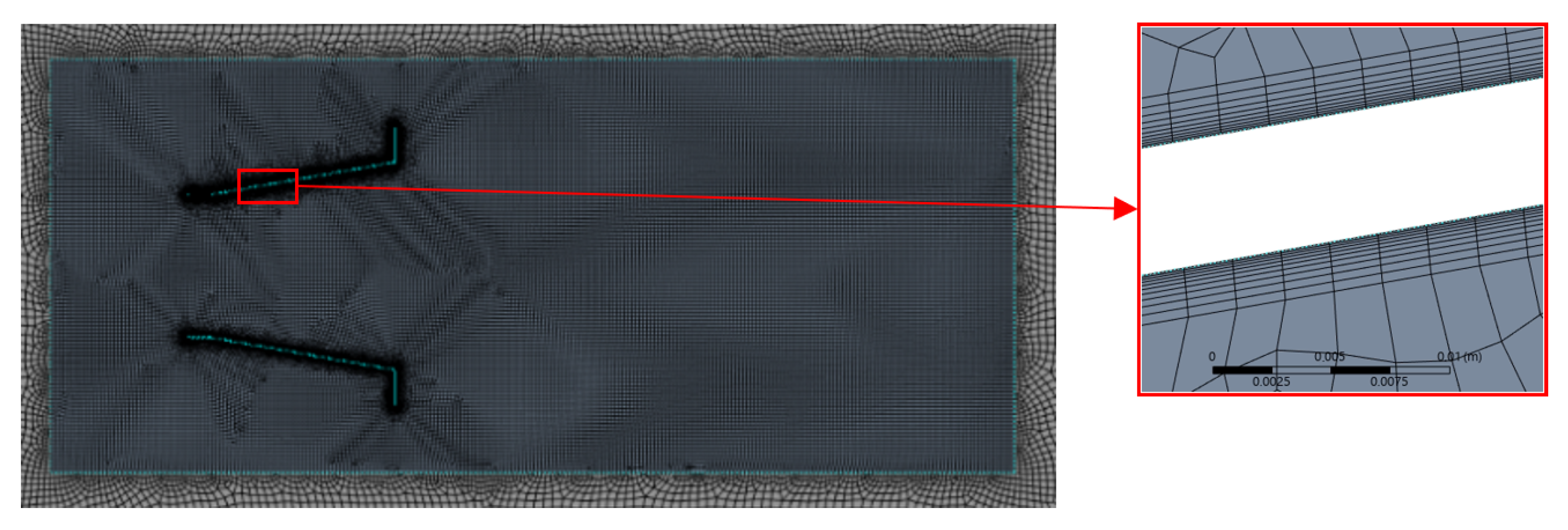
The computational domain (Figure 2) spans 20 D in the vertical direction and 31 D in the streamwise direction. To minimize inlet–outlet interactions, the diffuser was centred between 10 D downstream of the inlet and 21 D upstream of the outlet. A structured mesh with localised refinement around the diffuser walls and slot region was generated in ANSYS Fluent 2023R1. Inflation layers (10 layers, growth rate 1.2, first-layer height Δ y = 0.1 mm) ensured y + < 5 along all solid surfaces, as shown in Figure 3. A mesh independence study confirmed that 155 × 10 3 elements yielded changes below 3% in peak axial velocity.
Boundary conditions were applied as follows:
  • Inlet: Uniform velocity U = 1.5 m/s.
  • Outlet: Gauge pressure set to 0 Pa.
  • Walls: No-slip on diffuser and blade surfaces; slip (symmetry) on outer domain boundaries.
Transient simulations employed the PISO algorithm with a time step Δ t = 10 3 s, guaranteeing a maximum Courant number below 1.0. Second-order implicit time discretisation and second-order upwind spatial schemes were used for momentum and turbulence transport equations. Each case was run for 40s of physical time, by which point residuals had converged by at least four orders of magnitude and monitored velocity probes reached steady behaviour.
A mesh convergence study was performed to ensure numerical accuracy and computational efficiency. An initial global element size of 10 mm was successively halved until further refinement produced changes of less than 3% in the normalised axial velocity along the diffuser’s centreline. Mesh quality was verified against ANSYS™ guidelines (skewness < 0.35, orthogonal quality > 0.20) before each simulation [44].
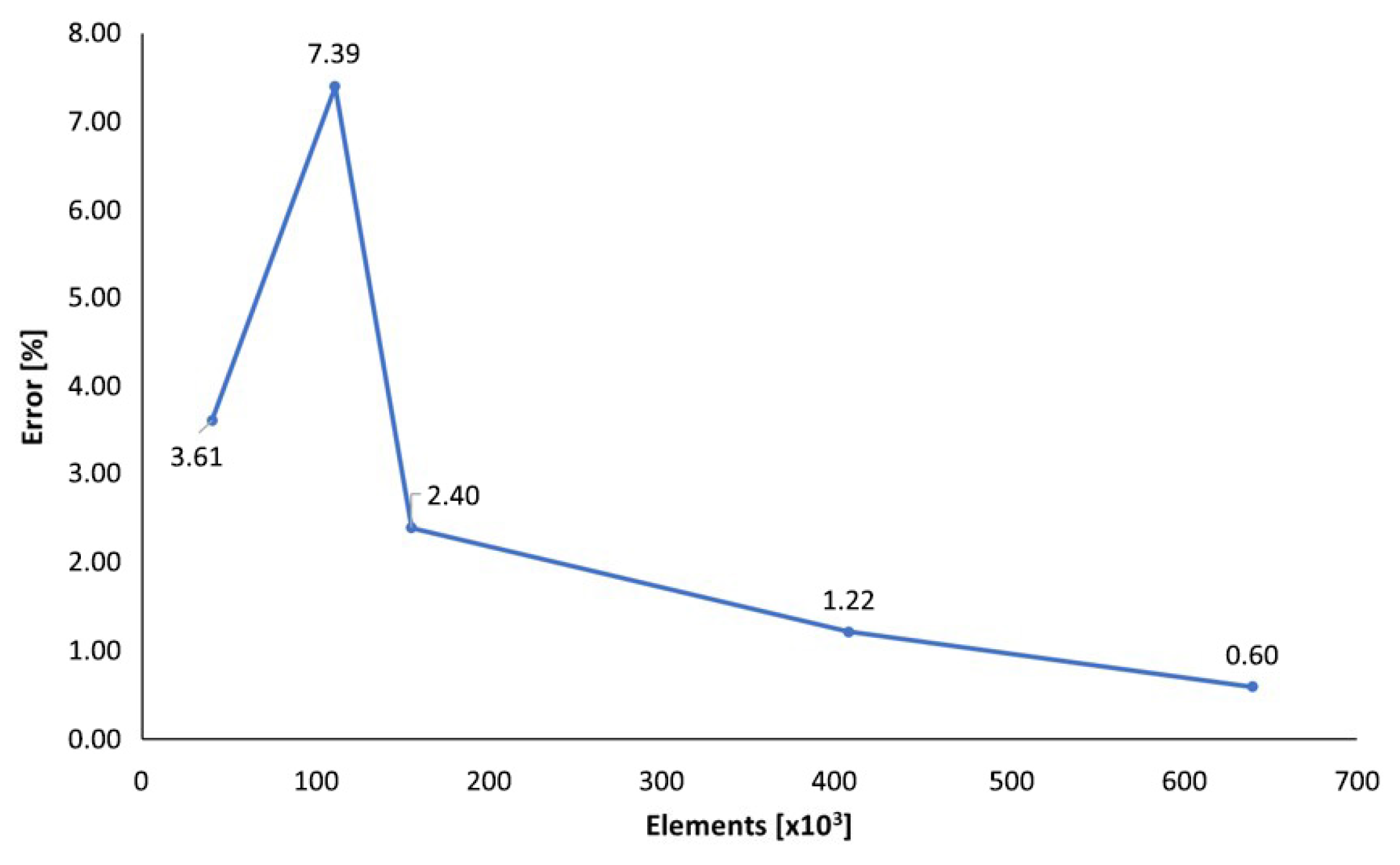
Six meshes were evaluated, containing approximately 13 × 10 3 , 40 × 10 3 , 111 × 10 3 , 155 × 10 3 , 407 × 10 3 , and 640 × 10 3 elements. The response metric was the average axial velocity along the symmetry axis, sampled from 2 D upstream to 4 D downstream of the diffuser [21,45,46]. Relative differences between successive meshes are plotted in Figure 4.
The mesh with 155 × 10 3 elements exhibited a relative error of 2.40% compared to the next finer grid, satisfying the convergence criterion. Consequently, all three diffuser geometries were discretised with this mesh density for consistent comparison.
The SST k ω turbulence model was selected for its well-established performance in predicting flow separation and adverse pressure gradients, as supported by previous studies [28,29]. This model combines the advantages of the k ω formulation near walls with the k ε model in the free stream, yielding improved accuracy for attached and mildly separated flows. While alternative models such as the realizable k ε and Reynolds Stress Model (RSM) could provide additional insights, especially in highly anisotropic turbulence, we prioritised model robustness and computational efficiency due to the large number of diffuser geometries evaluated. A comparative turbulence model sensitivity analysis is proposed as future work to complement the present geometric investigation.

3. Results

Accurate prediction of diffuser performance demands thorough validation of the numerical model against reliable benchmarks. Given the limited availability of experimental data for diffuser-augmented turbines, validation relies on reproducing published wind tunnel results. Once the model reproduces the reference case within acceptable error bounds, it is applied to the slotted configurations under study.

3.1. Numerical Validation

The RANS solver and mesh settings were validated against the experimental–theoretical dataset of Barboza et al. [47]. Their wind tunnel geometry and inlet conditions were replicated in both three-dimensional (3D) and two-dimensional (2D) simulations. Figure 5 overlays the normalised axial velocity U x / U along the diffuser centreline, plotted against the normalised distance x / D from the diffuser inlet.
The 3D simulation aligns closely with the experimental measurements, exhibiting a maximum deviation of 2%. The 2D model reproduces the overall velocity trend, but underestimates the peak by 6.4% relative to the 3D result. This discrepancy falls within the 6% error range reported by Rahmatian et al. for 2D vs. 3D diffuser simulations [33], confirming that the 2D model captures the essential flow features and is suitable for parametric investigation of slotted diffuser geometries.

3.2. Numerical Results

After validating the numerical model, the 2 3 factorial DOE analysis for Diffuser 1 was carried out. It was found that the geometry providing the best velocity profile performance inside Diffuser 1 corresponds to a divergence angle of 10° and a defined inlet section. Since the flange angle was found to have no statistically significant effect on the response variable in this study, the model with a flange angle of 90° was selected. Therefore, the geometry selected from the DOE for Diffuser 1 corresponds to Geometry 1; see Table 3.
Then, the 2 3 factorial DOE analysis was conducted for Diffuser 2. It was determined that the geometry providing the best velocity profile performance inside Diffuser 2 corresponds to a divergence angle of 10° and a Y-direction slot position of 0.0125D. Since the slot position in the X-direction was found to have no significant effect on the response variable, a value of 0.125D was selected. Therefore, the geometry selected from the DOE for Diffuser 2 corresponds to Geometry 3; see Table 4.
Finally, from a comprehensive analysis of the 2 3 factorial DOE for Diffuser 3, it was determined that the geometry providing the best velocity profile performance inside Diffuser 3 corresponds to a divergence angle θ of 2° and a Y-direction slot position of 0.01D. Since the divergence angle β was found to have no significant effect on the response variable, a value of 6° was selected. Therefore, the geometry selected from the DOE for Diffuser 3 corresponds to Geometry 1; see Table 5.
After conducting the numerical simulations for the 24 augmented diffuser geometries, one geometry was selected from each DOE based on the average axial velocity across the radial distance of the augmented diffuser. Finally, Figure 6 provides a summary of the selected designs for the three (3) augmented diffusers, listing the geometries identified through the application of each DOE.
After selecting the three augmented diffuser designs with the best performance, a detailed analysis was carried out to evaluate the influence of the selected geometric parameters on the velocity profile. Axial velocity contours and vector fields reveal the impact of slot placement and divergence angles on flow acceleration, separation, and uniformity. Figure 7 presents mid-plane contours of normalised axial velocity U x / U for all three diffuser configurations.
In the slotless design (Diffuser 1), the flow accelerates smoothly through the expansion section, achieving its maximum at x = 1.2 D . Downstream of this point, adverse pressure gradients induce large recirculation zones along the walls, as evidenced by near-wall backflow and transient fluctuations in the velocity profile. These separation eddies compromise both energy capture and structural loading consistency.
Introducing a single slot (Diffuser 2) injects external fluid into the main stream, which energizes the boundary layer and suppresses the most severe separation events. Although the peak axial velocity falls by 40% relative to the slotless design, the flow becomes markedly more uniform and steady. This stabilisation suggests lower unsteady loading on the turbine and improved overall hydraulic performance under variable inflow conditions.
Optimising the inlet divergence angle and relocating the slot closer to the outlet (Diffuser 3) further enhances flow quality. Separation zones shrink significantly, and near-wall reverse flow is almost eliminated. Compared to Diffuser 2, the peak axial velocity recovers by 19.8%, while the average normalised velocity along the symmetry axis increases from 1.044 to 1.426. These improvements indicate that the combined adjustment of geometric parameters yields the most uniform velocity distribution and the highest potential for consistent power extraction.
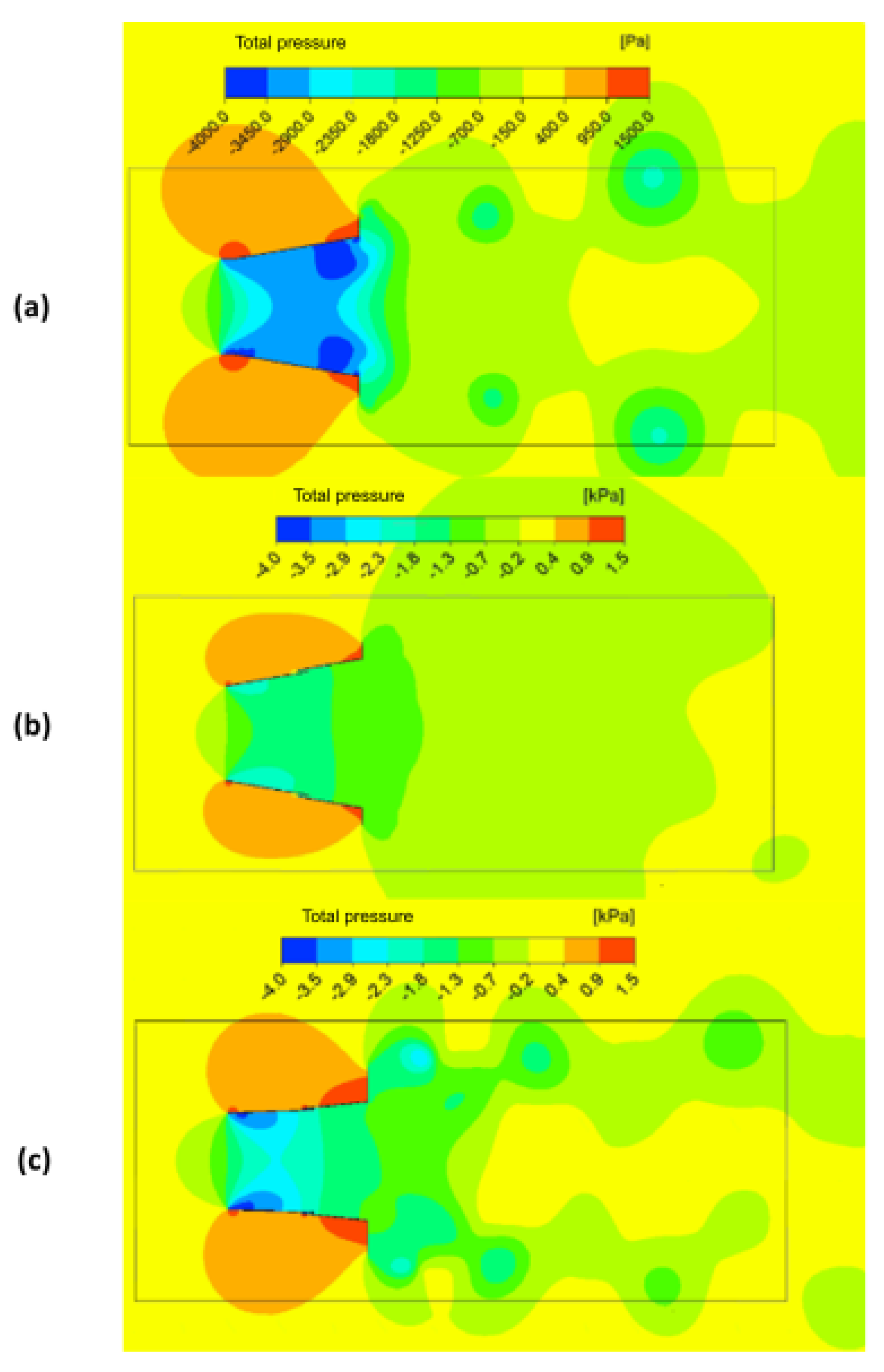
The total pressure distribution within the diffuser dictates the strength and location of favourable and adverse pressure gradients, which in turn influence both flow acceleration and separation behaviour. A detailed comparison of mid-plane total pressure contours (normalised by the inlet dynamic pressure, 1 2 ρ U 2 ) for the three designs is shown in Figure 8.
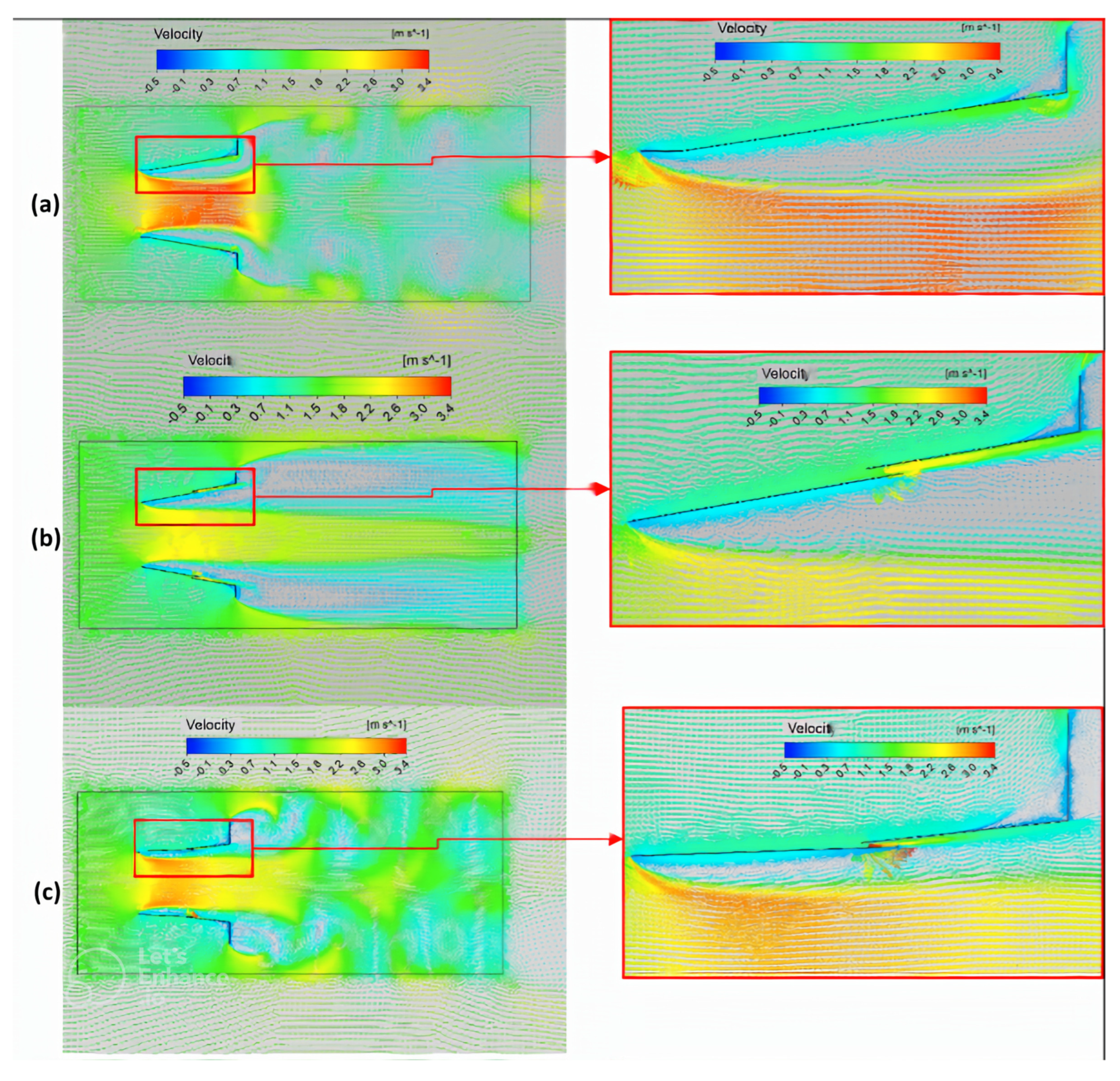
Velocity vector plots (Figure 9) and radial profiles at the location of peak flow (Figure 10) corroborate these findings: slot injection consistently reduces the size and intensity of recirculation eddies. In contrast, strategic slot positioning and angle reduction maximize axial acceleration and flow uniformity inside the diffuser.
In the slotless design (Figure 8a), the diffuser’s flange produces a pronounced high-pressure ridge at the outlet, evident as warm tones near the outer wall. Upstream of the inlet, a deep pressure trough develops, creating strong suction that draws fluid into the expansion. Between these regions, the gradient of total pressure reverses sharply, generating adverse forces that detach the boundary layer along the wall. The pressure recovery downstream of separation, with contours smoothing back toward freestream values, reflects energy losses in the recirculation zone and the associated turbulence generation.
Introducing a slot (Diffuser 2, Figure 8b) moderates the inlet pressure drop: the low-pressure region upstream of the inlet is shallower, indicating reduced suction intensity. Immediately downstream of the slot, a localised high-pressure patch appears, marking where the injected flow impinges on the mainstream. This local recovery acts to re-energize the boundary layer by replenishing momentum near the wall, thus limiting the spatial extent of separation. However, the slot’s injection also smooths the overall pressure gradient, lowering the flange-induced peak pressure by approximately 8% compared to the baseline, consistent with the 40% reduction in peak axial velocity noted in Section 3.2.
The optimised configuration (Diffuser 3, Figure 8c) combines a reduced inlet divergence angle with a slot relocated closer to the outlet. Here, the inlet pressure trough deepens slightly relative to Diffuser 2 (but remains less extreme than Diffuser 1), steering a stronger accelerating gradient through the expansion. The downstream slot injection again creates a pressure bump, but its location at x 2.5 D avoids interference with early-separation zones. Overall, the optimised design exhibits a more gradual pressure recovery: the contours transition smoothly from the low-pressure region to the flange ridge, indicating that boundary layer reattachment occurs more uniformly along the wall.
The velocity vector fields in Figure 9 further illustrate these effects. In the baseline, reversed vectors extend up to 0.2 D from the wall, signifying a large recirculation bubble. With the slot, this recirculation length shrinks by over 50% and downstream vectors align more closely with the freestream direction, indicating reduced shear layer thickness. The optimised design nearly eliminates upstream backflow: vectors remain within ±5° of the axial direction across most of the diffuser height, evidencing an almost attached boundary layer.
Radial profiles of normalised axial velocity U x / U at the axial station of maximum flow, shown in Figure 10, quantify the net impact on flow uniformity. The baseline profile features a flattened “top-hat” shape with a 5.6% lower peak and significant asymmetry due to unsteady separation. The slot raises the mean profile but widens the distribution, yielding an average U x / U = 1.044 . In contrast, the optimised slot concentrates momentum near the centreline, producing a Gaussian-like profile with an average of 1.426, an improvement of 12.6% over the baseline and 37.5% over the slot design. The standard deviation of U x / U across the channel height drops by 35%, indicating a more uniform flow that would reduce mechanical vibrations and increase adequate torque on the turbine shaft.
Taken together, the pressure and velocity analyses demonstrate that slot injection can be strategically deployed to tailor pressure gradients and boundary layer momentum. The optimised design’s balanced pressure trough and recovery, minimal separation, and peaked velocity profile suggest that it has the potential to yield the highest power coefficient and the most stable hydraulic loading among the configurations tested.

4. Discussion

The numerical results presented in this study reveal the significant role that diffuser geometry, and specifically slot design, plays in governing internal flow dynamics within hydrokinetic systems. Beyond enhancing peak axial velocity, the strategic integration of slot injection fundamentally alters the pressure recovery mechanism and boundary layer behaviour, suggesting new pathways for improving turbine efficiency and operational stability.
First, the reduction of boundary layer separation via slot injection suggests a promising avenue for extending operational reliability in low-Reynolds-number or variable-inflow environments, such as rivers with fluctuating discharge or tidal zones with intermittent reversals. The improved flow attachment observed in Diffuser 3 is not only beneficial for energy capture, but may also mitigate cyclic mechanical loads on the turbine structure. This has implications for reducing fatigue, life concerns, and maintenance intervals, all of which are required in remote deployments.
Second, the improved flow uniformity observed in Diffuser 3 suggests a more efficient aerodynamic alignment between the diffuser and the rotor design. A more homogeneous axial velocity field reduces flow distortion at the rotor interface, leading to greater torque consistency and potentially minimising the need for advanced control mechanisms or variable-pitch blades. This design simplification can lower overall system costs and enhance long-term operational robustness, particularly in micro-hydrokinetic applications where simplicity is a critical design factor. However, it is essential to account for specific site conditions, especially local flow velocities, as these may negatively impact marine fauna.
Interestingly, although Diffuser 2 exhibited a lower peak velocity compared to the slotless design, its enhanced flow stability may offer advantages in real applications such as fish-friendly turbines, where extreme velocities and high shear gradients must be avoided. Therefore, the choice of diffuser configuration should be application-specific, balancing maximum energy extraction with ecological or mechanical constraints.
It is also worth noting that the two-dimensional framework, while sufficient for capturing core flow trends, may overlook important three-dimensional effects such as vortex shedding, crossflow dynamics near the flange, and secondary flow structures at the slot edges. Experimental validation and fully three-dimensional simulations are proposed as interesting directions for future work.
The results suggest a broader methodological implication: diffuser design optimisation should not be confined to maximising axial velocity alone. Instead, future design procedures should incorporate multi-objective formulations that include flow uniformity, recirculation suppression, and mechanical loading stability as concurrent targets. Integrating such criteria into a parametric design space exploration, potentially through surrogate modelling or bio-inspired algorithms, could yield generalised diffuser topologies that are suitable for diverse hydrokinetic environments.
Although the improved flow uniformity and reattachment observed in Diffuser 3 suggest beneficial boundary layer dynamics, a detailed quantitative analysis of the momentum transfer mechanism was not performed in this initial study. Specifically, shear stress distributions and boundary layer thickness evolution were not extracted from the simulations. Future work will address this by evaluating the momentum thickness and wall shear stress profiles, allowing deeper insight into how slot location and divergence angles interact to promote or inhibit flow separation. This analysis would also help to bridge the results with classical boundary layer theory.

5. Conclusions

5.1. Key Conclusions

This study has demonstrated that the integration of a single slot into a straight-walled diffuser significantly alters the internal flow dynamics by re-energising the boundary layer and suppressing extensive recirculation zones. Among the three configurations analysed, Diffuser 3, characterised by a reduced inlet divergence angle (2°), an outlet divergence angle of 6°, and a slot positioned at 0.01D in the Y-direction and 0.125D in the X-direction, achieved the most uniform axial velocity distribution and the highest momentum concentration along the central axis. Quantitatively, the configurations of Diffusers 1, 2, and 3 exhibited increases in axial velocity relative to the flow without a diffuser of 26.9%, 4.6%, and 42.6%, respectively.
Furthermore, the results obtained from the Designs of Experiments (DOEs) indicate that the slot position along the X-axis has little influence on the average axial velocity. In contrast, variations along the Y-axis have a significant impact. These findings underscore the importance of slot placement in the design of augmented diffusers and highlight the need for further investigation into the effects of alternative X and Y positions on internal flow behaviour.
The results also indicate that divergence angles beyond 10° exacerbate adverse pressure gradients, leading to earlier separation and unsteady fluctuations that degrade flow quality. In contrast, carefully tailored slot placement can both moderate inlet suction and generate localised pressure recovery downstream, thereby sustaining attached flow and maximising kinetic energy delivery to the turbine rotor.

5.2. Limitations and Future Work

For future diffuser-augmented HKT designs, the average axial velocity along the symmetry axis is recommended as a primary performance metric, since it directly reflects the net energy available for extraction. Further investigations should explore multi-slot arrangements, detailed slot geometry (width, number, and angular orientation), and three-dimensional effects to refine diffuser performance. Experimental validation in a controlled facility would also strengthen confidence in these numerical findings and support scale-up to prototype turbines. Despite the promising results, several limitations must be acknowledged. The study employed a two-dimensional numerical model under transient-inflow conditions, which, while sufficient for capturing primary flow phenomena, does not account for three-dimensional effects such as azimuthal vorticity, lateral slot wake interactions, or swirl generated by turbine blades. Furthermore, the impact of diffuser geometry on turbine loading and efficiency was inferred from flow metrics alone, without direct coupling to rotor dynamics. Future work should address these limitations by conducting fully three-dimensional simulations that include rotor–diffuser interaction and transient-inflow effects. Experimental validation in a controlled hydraulic test facility is also essential for confirming numerical predictions and evaluating real-world manufacturing. Additional investigations should explore multi-slot designs, vary slot width and orientation, and assess the influence of turbulence intensity on diffuser performance.

Author Contributions

Conceptualisation, D.S.-V. and J.S.-D.R.; methodology, D.S.-V., S.G.-H., and J.S.-D.R.; software, S.G.-H. and D.H.Z.; formal analysis, J.S.-D.R. and D.H.Z.; investigation, D.S.-V. and D.H.Z.; data curation, S.G.-H. and D.H.Z.; writing—original draft preparation, D.S.-V. and S.G.-H.; writing—review and editing, J.S.-D.R. and D.S.-V.; visualisation, S.G.-H. and D.H.Z.; supervision, J.S.-D.R.; project administration, D.S.-V.; funding acquisition, D.S.-V. All authors have read and agreed to the published version of the manuscript.

Funding

This research received no external funding.

Data Availability Statement

Data are available upon request.

Acknowledgments

The authors used Grammarly 1.112.1.0 and ChatGPT 4o to improve their writing and style. After using this tool, the authors reviewed and edited the content as needed, and they take full responsibility for the publication’s content.

Conflicts of Interest

The authors declare no conflicts of interest.

References

  1. Sopian, K.; Ali, B.; Asim, N. Strategies for Renewable Energy Applications in the Organization of Islamic Conference (OIC) Countries. Renew. Sustain. Energy Rev. 2011, 15, 4706–4725. [Google Scholar] [CrossRef]
  2. International Energy Agency. World Energy Outlook 2006; IEA: Paris, France, 2006. [Google Scholar] [CrossRef]
  3. Dincer, I. Renewable Energy and Sustainable Development: A Crucial Review. Renew. Sustain. Energy Rev. 2000, 4, 157–175. [Google Scholar] [CrossRef]
  4. Elbatran, A.H.; Yaakob, O.B.; Ahmed, Y.M.; Shabara, H.M. Operation, Performance and Economic Analysis of Low Head Micro-Hydropower Turbines for Rural and Remote Areas: A Review. Renew. Sustain. Energy Rev. 2015, 43, 40–50. [Google Scholar] [CrossRef]
  5. Vermaak, H.J.; Kusakana, K.; Koko, S.P. Status of Micro-Hydrokinetic River Technology in Rural Applications: A Review of Literature. Renew. Sustain. Energy Rev. 2014, 29, 625–633. [Google Scholar] [CrossRef]
  6. Shahsavarifard, M.; Bibeau, E.L. Yaw operation of a shrouded horizontal axis hydrokinetic turbine. In Proceedings of the MTS/IEEE OCEANS 2015—Genova: Discovering Sustainable Ocean Energy for a New World, Genova, Italy, 18–21 May 2015; pp. 1–4. [Google Scholar] [CrossRef]
  7. Muñoz, A.H.; Chiang, L.E.; De la Jara, E.A. A Design Tool and Fabrication Guidelines for Small Low Cost Horizontal Axis Hydrokinetic Turbines. Energy Sustain. Dev. 2014, 22, 21–33. [Google Scholar] [CrossRef]
  8. Arrieta, E.L.C.; Cardona-Mancilla, C.; Slayton, J.; Romero, F.; Torres, E.; Agudelo, S.; Arbelaez, J.J.; Hincapié, D. Experimental Investigations and CFD Simulations of the Blade Section Pitch Angle Effect on the Performance of a Horizontal-Axis Hydrokinetic Turbine. Eng. J. 2018, 22, 141–154. [Google Scholar] [CrossRef]
  9. Shaabani, B.; Chatoorgoon, V.; Bibeau, E.L. Using numerical analysis to design and optimize river hydrokinetic turbines’ capacity factor to address seasonal velocity variations. Energies 2025, 18, 477. [Google Scholar] [CrossRef]
  10. Chica, E.; Aguilar, J.; Rubio-Clemente, A. Analysis of a Lift Augmented Hydrofoil for Hydrokinetic Turbines. Renew. Energy Power Qual. J. 2019, 17, 49–55. [Google Scholar] [CrossRef]
  11. Shen, C.; Han, Y.; Wang, S.; Wang, Z. Influence of airfoil curvature and blade angle on vertical axis hydraulic turbine performance in low flow conditions. Water 2025, 17, 11. [Google Scholar] [CrossRef]
  12. Gomez, M.A.; Guevara-Muñoz, A.; Zuluaga, D.H. A Numerical H-Darrieus Hydrokinetic Turbine Performance Assessment with the Application of Openings in Blade Geometry. Int. J. Renew. Energy Dev. 2025, 14, 1–9. [Google Scholar] [CrossRef]
  13. Kim, D.G.; Kim, J.; Jung, S.; Ko, J.H. Experimental investigation of the yaw misalignment effect on the power performance and system loading of a flapping-foil hydrokinetic turbine. Energy Sci. Eng. 2024, 12, 5555–5565. [Google Scholar] [CrossRef]
  14. Taborda, D.G.; Del Rio, J.S.; Perez-Alvarez, J.D.; Cardona-Vargas, A.; Sanin, D.S. CFD Analysis of the Needle Tip Angle in Pelton Injector on Jet Quality for the Power Generation. EUREKA Phys. Eng. 2021, 3, 45–59. [Google Scholar] [CrossRef]
  15. Sánchez, A.R.; Del Rio, J.A.S.; Quintana, E.C.; Sanín-Villa, D. Numerical Comparison of Savonius Turbine as a Rotor for Gravitational Vortex Turbine with Standard Rotor. J. Appl. Eng. Sci. 2023, 21, 204–211. [Google Scholar] [CrossRef]
  16. Del Rio, J.A.S.; Sánchez, A.R.; Sanín-Villa, D.; Quintana, E.C. Numerical Study of H-Darrieus Turbine as a Rotor for Gravitational Vortex Turbine. CFD Lett. 2022, 14, 1–11. [Google Scholar] [CrossRef]
  17. Kolekar, N.; Mukherji, S.S.; Banerjee, A. Numerical modeling and optimization of hydrokinetic. In Proceedings of the ASME 2011 5th International Conference on Energy Sustainability, Washington, DC, USA, 7–10 August 2011; pp. 1–8. [Google Scholar]
  18. Jamieson, P.M. Beating Betz: Energy extraction limits in a constrained flow field. J. Sol. Energy Eng. Trans. ASME 2009, 131, 031008. [Google Scholar] [CrossRef]
  19. Nunes, M.M.; Brasil Junior, A.C.P.; Oliveira, T.F. Systematic Review of Diffuser-Augmented Horizontal-Axis Turbines. Renew. Sustain. Energy Rev. 2020, 133, 110075. [Google Scholar] [CrossRef]
  20. Abdelwaly, M.; El-Batsh, H.; Bassily Hanna, M. Numerical Study for the Flow Field and Power Augmentation in a Horizontal Axis Wind Turbine. Sustain. Energy Technol. Assess. 2019, 31, 245–253. [Google Scholar] [CrossRef]
  21. Silva, P.A.S.F.; Rio Vaz, D.A.T.D.; Britto, V.; de Oliveira, T.F.; Vaz, J.R.P.; Brasil Junior, A.C.P. A New Approach for the Design of Diffuser-Augmented Hydro Turbines Using the Blade Element Momentum. Energy Convers. Manag. 2018, 165, 801–814. [Google Scholar] [CrossRef]
  22. Saha, G. Performance Improvement of Self-Rectifying Axial Impulse Turbines with a Diffuser Integration Strategy. In Proceedings of the 15th European Wave and Tidal Energy Conference (EWTEC 2023), Bilbao, Spain, 3–7 September 2023; University of Southampton: Southampton, UK, 2023. [Google Scholar] [CrossRef]
  23. Mehmood, N.; Liang, Z.; Khan, J. CFD Study of NACA 0018 for Diffuser Design of Tidal Current Turbines. Res. J. Appl. Sci. Eng. Technol. 2012, 4, 4552–4560. [Google Scholar]
  24. Tampier, G.; Troncoso, C.; Zilic, F. Numerical Analysis of a Diffuser-Augmented Hydrokinetic Turbine. Ocean Eng. 2017, 145, 138–147. [Google Scholar] [CrossRef]
  25. Song, K.; Wang, W.; Yan, Y. Numerical and Experimental Analysis of a Diffuser-Augmented Micro-Hydro Turbine. Ocean Eng. 2019, 171, 590–602. [Google Scholar] [CrossRef]
  26. Vaz, J.R.P.; Wood, D.H. Aerodynamic Optimization of the Blades of Diffuser-Augmented Wind Turbines. Energy Convers. Manag. 2016, 123, 35–45. [Google Scholar] [CrossRef]
  27. Park, J.; Lee, H.; Kim, S.; Choi, Y. CFD-Based Design Optimization of a 5 kW Ducted Hydrokinetic Turbine with Practical Constraints. arXiv 2024, arXiv:2411.13492. [Google Scholar] [CrossRef]
  28. Vaz, J.R.P.; de Lima, A.K.F.; Lins, E.F. Assessment of a Diffuser-Augmented Hydrokinetic Turbine Designed for Harnessing the Flow Energy Downstream of Dams. Sustainability 2023, 15, 7671. [Google Scholar] [CrossRef]
  29. Ng, C.Y.; Maldar, N.R.; Ong, M.C. Numerical Investigation on Performance Enhancement in a Drag-Based Hydrokinetic Turbine with a Diffuser. Ocean Eng. 2024, 298, 117179. [Google Scholar] [CrossRef]
  30. Arrieta-Gomez, M.; Vélez-García, S.; Hincapie, D.; Tejada, J.C.; Sanin-Villa, D. Efficiency Optimization of a Hybrid Savonius-Darrieus Hydrokinetic Turbine via Regression Modeling and CFD-Based Design of Experiments. Results Eng. 2025, 27, 105751. [Google Scholar] [CrossRef]
  31. Limacher, E.J.; da Silva, P.O.C.; Barbosa, P.E.S.; Vaz, J.R.P. Large Exit Flanges in Diffuser-Augmented Turbines Lead to Sub-Optimal Performance. J. Wind Eng. Ind. Aerodyn. 2020, 204, 104228. [Google Scholar] [CrossRef]
  32. Igra, O. Compact Shrouds for Wind Turbines. Energy Convers. 1977, 16, 149–157. [Google Scholar] [CrossRef]
  33. Rahmatian, M.A.; Hashemi Tari, P.; Mojaddam, M.; Majidi, S. Numerical and Experimental Study of the Ducted Diffuser Effect on Improving the Aerodynamic Performance of a Micro Horizontal Axis Wind Turbine. Energy 2022, 245, 123267. [Google Scholar] [CrossRef]
  34. Abe, K.I.; Ohya, Y. An Investigation of Flow Fields around Flanged Diffusers Using CFD. J. Wind Eng. Ind. Aerodyn. 2004, 92, 315–330. [Google Scholar] [CrossRef]
  35. Gilbert, B.L. Investigation of Diffuser-Augmented Wind Turbines. Part II. J. Wind Eng. Ind. Aerodyn. 1977, 2. [Google Scholar] [CrossRef]
  36. Sorribes-Palmer, F.; Sanz-Andrés, A.; Ayuso, L.; Sant, R.; Franchini, S. Mixed CFD–1D Wind Turbine Diffuser Design Optimization. Renew. Energy 2017, 105, 386–399. [Google Scholar] [CrossRef]
  37. Toshimitsu, K.; Nishikawa, K.; Haruki, W.; Oono, S.; Takao, M.; Ohya, Y. PIV Measurements of Flows around the Wind Turbines with a Flanged-Diffuser Shroud. J. Therm. Sci. 2008, 17, 375–380. [Google Scholar] [CrossRef]
  38. Foreman, K.M.; Gilbert, B.; Oman, R.A. Diffuser Augmentation of Wind Turbines; Technical Report Report 20; Oregon State University: Corvallis, OR, USA, 1976. [Google Scholar]
  39. Gilbert, B.L.; Oman, R.A.; Foreman, K.M. Investigation of Diffuser-Augmented Wind Turbines. Part I. J. Wind Eng. Ind. Aerodyn. 1977, 7, 541–559. [Google Scholar]
  40. Argyropoulos, C.D.; Markatos, N.C. Recent Advances on the Numerical Modelling of Turbulent Flows. Appl. Math. Model. 2015, 39, 693–732. [Google Scholar] [CrossRef]
  41. ANSYS Inc. Ansys Fluent User’s Guide; ANSYS Inc.: Canonsburg, PA, USA, 2021. [Google Scholar]
  42. Barbarić, M.; Guzović, Z. Investigation of the Possibilities to Improve Hydrodynamic Performances of Micro-Hydrokinetic Turbines. Energies 2020, 13, 4560. [Google Scholar] [CrossRef]
  43. Picanço, H.P.; de Lima, A.K.F.; Vaz, D.A.T.D.; Lins, E.F.; Vaz, J.R.P. Cavitation Inception on Hydrokinetic Turbine Blades Shrouded by Diffuser. Sustainability 2022, 14, 7067. [Google Scholar] [CrossRef]
  44. ANSYS Inc. Introduction to Ansys Meshing; ANSYS Inc.: Canonsburg, PA, USA, 2012. [Google Scholar]
  45. Leloudas, S.N.; Lygidakis, G.N.; Eskantar, A.I.; Nikolos, I.K. A Robust Methodology for the Design Optimization of Diffuser-Augmented Wind Turbine Shrouds. Renew. Energy 2020, 150, 722–742. [Google Scholar] [CrossRef]
  46. Khamlaj, T.A.; Rumpfkeil, M.P. Analysis and Optimization of Ducted Wind Turbines. Energy 2018, 162, 1234–1252. [Google Scholar] [CrossRef]
  47. Barbosa, D.L.M.; Vaz, J.R.P.; Figueiredo, S.W.O.; de Oliveira e Silva, M.; Lins, E.F.; Mesquita, A.L.A. An Investigation of a Mathematical Model for the Internal Velocity Profile of Conical Diffusers Applied to DAWTs. An. Acad. Bras. Ciênc. 2015, 87, 1133–1148. [Google Scholar] [CrossRef][Green Version]
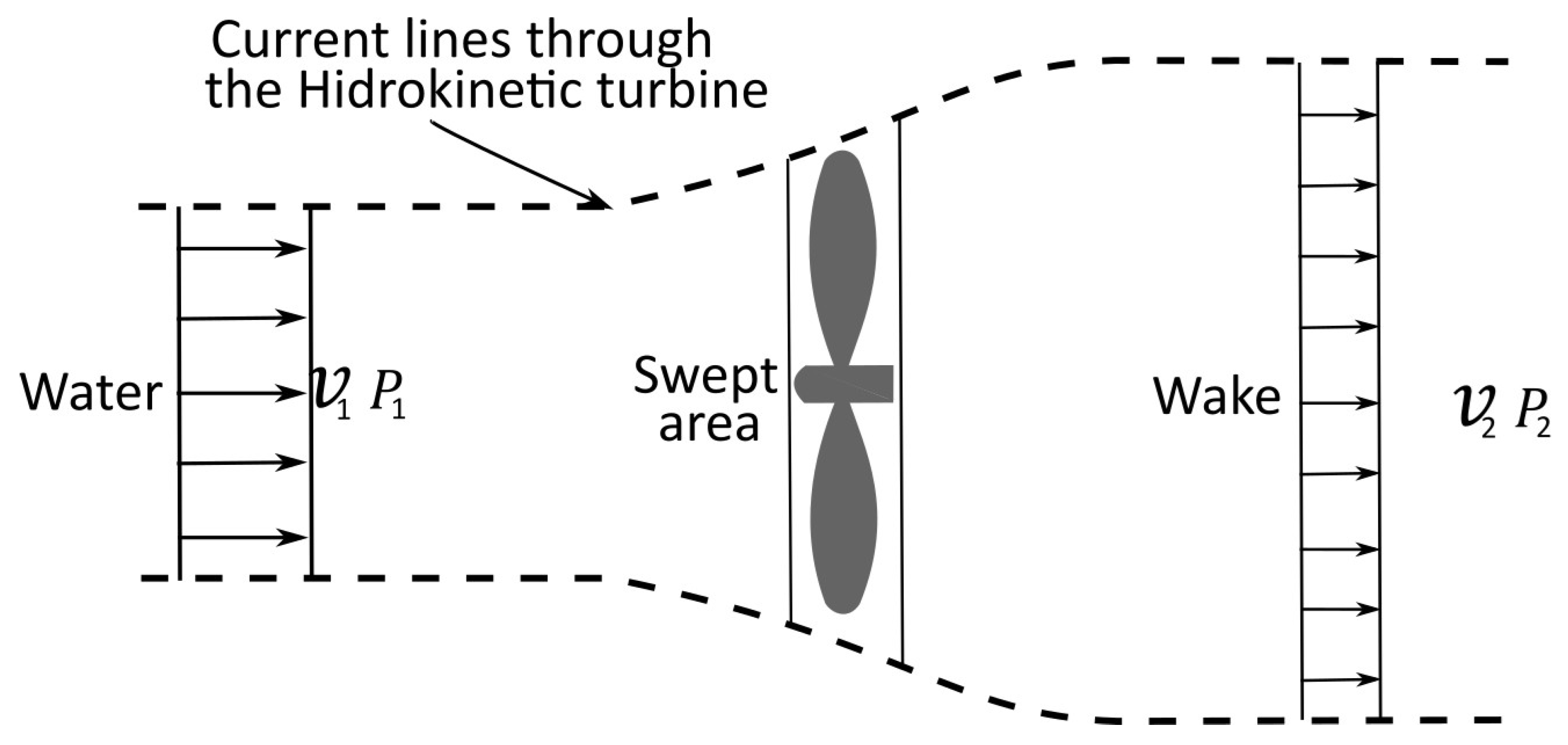
Figure 1. Schematic of flow acceleration and deceleration around a horizontal-axis hydrokinetic turbine.
Asi 08 00129 g001
Figure 2. Computational domain normalised by rotor diameter D; shaded region indicates fine-mesh zone around diffuser.
Asi 08 00129 g002
Figure 3. Mesh for volume discretisation.
Asi 08 00129 g003
Figure 4. Mesh independence study: element count vs. relative error in mean axial velocity on the diffuser centreline.
Asi 08 00129 g004
Figure 5. Comparison of normalised axial velocity profiles: experimental data from Barboza et al. [47] (blue), present 3D RANS results (green), and present 2D RANS results (orange).
Asi 08 00129 g005
Figure 6. Normalised parameterisation of the three diffuser configurations.
Asi 08 00129 g006
Figure 7. Mid-plane contours of normalised axial velocity U x / U for (a) Diffuser 1, (b) Diffuser 2, and (c) Diffuser 3.
Asi 08 00129 g007
Figure 8. Mid-plane total pressure contours (normalised by inlet dynamic pressure) for (a) Diffuser 1, (b) Diffuser 2, and (c) Diffuser 3.
Asi 08 00129 g008
Figure 9. Mid-plane velocity vectors (normalised by U) for (a) Diffuser 1, (b) Diffuser 2, and (c) Diffuser 3.
Asi 08 00129 g009
Figure 10. Radial profiles of normalised axial velocity U x / U at the axial station of maximum flow for the three diffuser configurations.
Asi 08 00129 g010
Table 1. Diffuser geometric parameters (normalised by rotor diameter D).
ParameterDefinition
α Flange angle at diffuser outlet
θ Divergence angle of first section
β Divergence angle of second section
D in Inlet diameter
D flange Outlet flange diameter
cLength of straight inlet section
L t Total diffuser length
Δ r Radial clearance between rotor and wall
hFlange height
XAxial position of slot
YRadial position of slot
LDistance from slot to diffuser outlet
Table 2. Designs of experiments. Source: Own elaboration.
Asi 08 00129 i001DOE 1—Straight-Walled Diffuser
FactorDescriptionLevel 1Level 2Refs.
P 1 = θ Divergence angle (°)1016[31,32]
P 2 = α Flange angle (°)9075[21,31,33]
P 3 = c Inlet sectionWith inletWithout inlet[21,33,34]
Asi 08 00129 i002DOE 2—Single-Slot Diffuser
FactorDescriptionLevel 1Level 2Refs.
P 1 = θ Divergence angle (°)1016[31,32]
P 2 = Y Slot Y-position0.0125 D0.04 D[35,36]
P 3 = X Slot X-position0.250 D0.125 D[35,36]
Asi 08 00129 i003DOE 3—Dual-Angle Diffuser
FactorDescriptionLevel 1Level 2Refs.
P 1 = θ Divergence angle 1 (°)24[21,37]
P 2 = β Divergence angle 2 (°)68[31,38]
P 3 = Y Slot Y-position0.01 D0.06 D[35,36,39]
Table 3. Response variable behaviour from the 2 3 factorial DOE for Diffuser 1.
GeometryDivergence Angle (°)Flange Angle (°)Inlet SectionAverage Normalised Axial Velocity
51690With inlet0.975
71675With inlet0.906
81675Without inlet0.889
31075With inlet1.227
21090Without inlet1.106
41075Without inlet1.084
61090With inlet0.897
11690With inlet1.269
Table 4. Response variable behaviour from the 2 3 factorial DOE for Diffuser 2.
GeometryDivergence Angle (°)Slot Y-PositionSlot X-PositionAverage Normalised Axial Velocity
8160.0400 D0.125 D0.857
6160.0400 D0.250 D0.835
3100.0125 D0.125 D1.044
7100.0400 D0.125 D1.046
2160.0125 D0.250 D0.853
1100.0125 D0.250 D1.044
5100.0400 D0.250 D1.044
4160.0125 D0.125 D0.848
Table 5. Response variable behaviour from the 2 3 factorial DOE for Diffuser 3.
GeometryDivergence Angle 1 (°)Divergence Angle 2 (°)Slot Y-PositionAverage Normalised Axial Velocity
84100.06 D1.313
2460.01 D1.329
5260.06 D1.387
32100.01 D1.394
44100.01 D1.310
6460.06 D1.304
1260.01 D1.426
72100.06 D1.387
Disclaimer/Publisher’s Note: The statements, opinions and data contained in all publications are solely those of the individual author(s) and contributor(s) and not of MDPI and/or the editor(s). MDPI and/or the editor(s) disclaim responsibility for any injury to people or property resulting from any ideas, methods, instructions or products referred to in the content.