Review

Accelerometers in Monitoring Systems for Rail Vehicle Applications: A Literature Review

1
Electromechanical and Electromagnetic Systems & Technologies Department, National Institute for Research and Development in Electrical Engineering ICPE-CA, 030138 Bucharest, Romania
2
Tehmin-Brașov, 507015 Brașov, Romania
3
Rolling Stock Department, National University of Science and Technology POLITEHNICA Bucharest, 060042 Bucharest, Romania
*
Authors to whom correspondence should be addressed.
Appl. Syst. Innov. 2025, 8(3), 70; https://doi.org/10.3390/asi8030070
Submission received: 18 March 2025 / Revised: 13 May 2025 / Accepted: 22 May 2025 / Published: 26 May 2025

Abstract

This document comprehensively analyses the literature on accelerometers used in monitoring systems designed for rail vehicle applications. It reviews the current research on this topic and highlights key findings, methodologies, and trends in the field. Additionally, it discusses the role of accelerometers in enhancing safety and performance within rail vehicle systems. This review is structured into several sections: Introduction, Fundamentals of Accelerometer Data, Signal-Processing Techniques, Examples of Accelerometers Used in Railway Monitoring Systems, and a Guide for Choosing the Right Accelerometer. One of the primary contributions of this paper is recommending the best accelerometer in terms of cost and performance for use in the rail vehicle industry. Future work will consider using an online detection tool for the acceleration of the frame of the railway coach and signalization of the peak values using the train intercom to the driver and static diagnosis systems. This approach aims to facilitate the detection of track irregularities, wind influence, and failures of the coach suspensions, which can be easily detected.

1. Introduction

1.1. Acceleration Sensors

An accelerometer is a device that measures an object’s proper acceleration relative to an observer in free fall. For example, an accelerometer at rest on the surface of the Earth will measure an acceleration of approximately 9.81 m/s2.
Accelerometers are used in industry, consumer products, and science and technology. They are used for navigation and stabilizing systems aboard aircrafts, rockets, and unmanned aircraft vehicles. In consumer electronics, they are used inside smartphones and video cameras to help stabilize and detect the orientation of these devices. Industry applications of accelerometers include the vibration detection of industrial machinery such as motors or conveyors. An essential application of accelerometer and vibration measurements is detecting ground movement, especially earthquakes.

1.2. Working Principle of Accelerometer

The basic accelerometer comprises a proof mass (or seismic mass) suspended by a spring. When the device experiences acceleration, the spring is compressed and exerts a force on the mass to counteract that acceleration [1,2]. Figure 1 presents the basic working principle of an accelerometer. To simplify the calculation, we consider only an accelerometer experiencing a force in the x direction.
A spring constant characterizes the spring, denoted k, representing the force that varies linearly with the amount of compression, and by knowing the mass m and spring constant, the amount of compression represents a measure of the perturbed force. There is a dumping involved, characterized by the β dumping coefficient. Dumping is necessary to explain why the oscillations will be amortized in time. To obtain the acceleration a, we measure x, and we use the following equations:
m · x ¨ + 2 · ζ · ω n · x ˙ + ω n 2 · x = a
The natural frequency ωn and the dumping ratio ζ determine the behavior of this dynamic system. Equations (2) and (3) describe their expressions.
ω n = k / m
ζ = β / 4 · m · k
Using those parameters, the equation of the movement becomes as follows:
  x ¨ + 2 · ζ · ω n · x + ω n 2 · x = a
The solution of this equation represents the transient response, which depends on the initial conditions, and a steady-state response, which is independent of initial conditions. For a fast enough system, the transient response can be ignored. The steady-state equation can be written as follows:
  m · a = k · x
An upper boundary of the bandwidth of an open-loop accelerometer is its natural frequency ωn. It can be seen that the bandwidth of an accelerometer sensing element has to be traded off with its sensitivity. Sensitivity is defined by Equation (5).
  S = x a = m k = 1 ω n 2
The Laplace transform of Equation (4) can describe the dynamic behavior:
  x ( s ) a ( s ) = 1 s 2 + β m · s + k m
The damping coefficient β is crucial for an accelerometer’s dynamic performance. For maximum bandwidth, the proof mass should be critically damped, a fact that is not easy to achieve technologically.

1.3. Types of Accelerometers

There are many types of accelerometers. The following list enumerates various devices, classified by the operating principle.

1.3.1. Machined Piezoelectric Resistive

When a piezoelectric material experiences stress, it generates an electrical charge. When paired with a seismic mass, it can produce an electric charge signal that is proportional to the acceleration of vibrations. While they tend to be pricier than other sensor types, piezoelectric accelerometers offer significant benefits [3,4]:
  • This system has a very wide dynamic range and produces almost no noise. It is suitable for measuring shocks and can also detect vibrations that are barely noticeable;
  • This system has the best linearity in the dynamic range;
  • This system has a side frequency range—very high frequencies can be measured;
  • This system is compact and sensitive;
  • This system has no moving parts (reliable);
  • This system has no need for an external supply;
  • This system has different models available;
  • This system has speed and displacement that can be computed using output data.

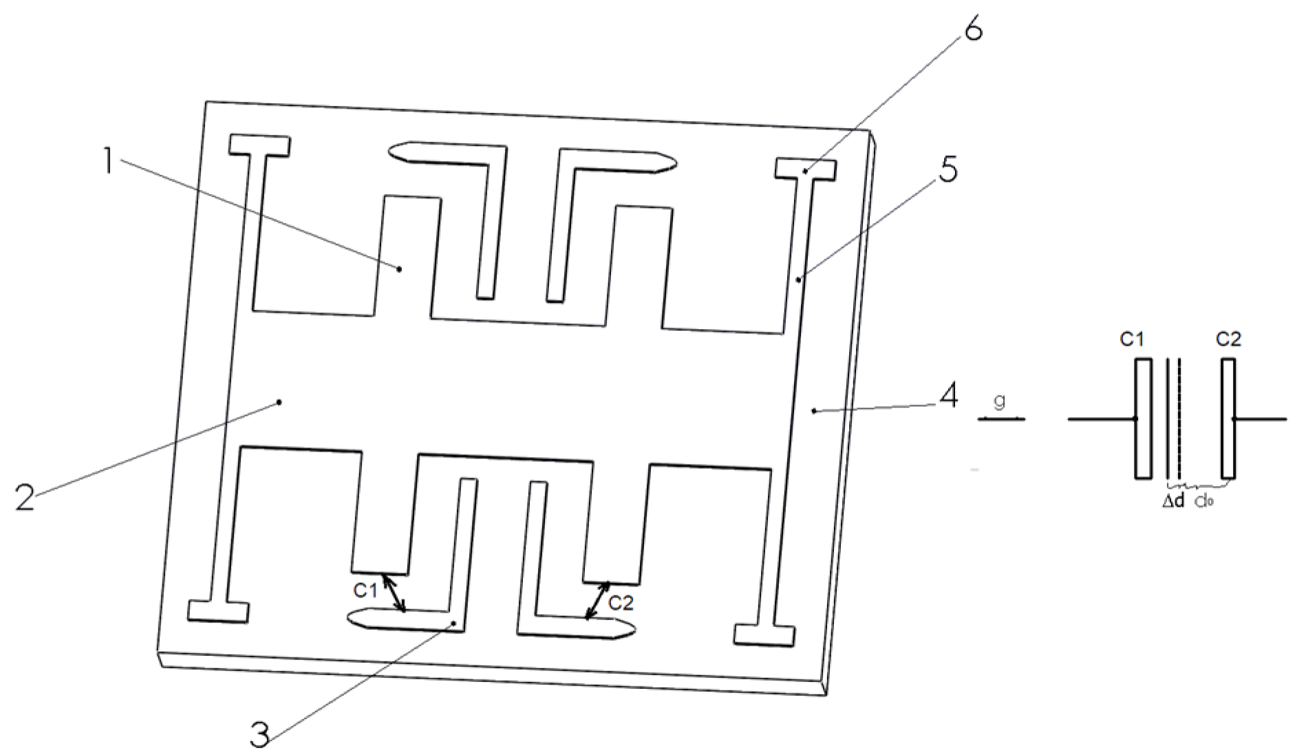
1.3.2. Capacitive Spring-Mass System Base

A capacitive accelerometer detects acceleration by measuring the displacement of a proof mass relative to its housing. Capacitive accelerometers are ideal for monitoring large structures due to their ability to measure a wide frequency range, including static acceleration, while providing greater stability, sensitivity, and resolution than piezoresistive accelerometers. However, they are highly sensitive to fluctuations in temperature and humidity, making them considerably more fragile than piezoelectric ones [5,6].

1.3.3. Laser Accelerometer

A laser accelerometer uses a laser to measure changes in speed/direction. It has a frame with three orthogonal input axes and multiple proof masses. Each proof mass is supported by a predetermined surface. A flexible beam holds each proof mass and allows the proof mass to move along its axis. When there is an acceleration towards the input axis, the proof mass bends the beam. This movement shifts the blanking surface across the light ray, which partially blocks the light beam [7].

1.3.4. Magnetic Induction

A magnetic accelerometer is designed based on the unique physical properties of the magnetic fluid. Compared with conventional acceleration sensors, magnetic fluid accelerometers have more substantial shock resistance, sensitivity, lower energy consumption, leading to a better performance when operating with low-frequency movements [8,9].

1.3.5. Optical

The optical accelerometer’s operation principle is based on the seismic mass effect, with an optical fiber cantilever beam as the spring-mass system. This permits the registration of the seismic mass’s instant position relative to the sensor’s housing through the light conveyed by this fiber [10,11,12].

1.3.6. Surface Acoustic Wave (SAW)

Surface acoustic wave sensors are small devices that use sound waves on their surface to detect physical changes. They are a type of microelectromechanical system (MEMS). Unlike an electrical signal, the sensor transduces an input electrical signal into a mechanical wave, which physical phenomena can easily influence. This device subsequently transduces the wave back into an electrical signal. Variations in amplitude, phase, frequency, or time delay between input and output electrical signals can be utilized to detect the presence of the targeted phenomenon [13]. These sensors are of marginal importance and are not mass-produced.

1.4. Particular Types of Accelerometers

The accelerometers listed in this subchapter are particular accelerometers specially designed for dedicated applications.

1.4.1. Seat Pad Accelerometers

Research utilizing data collected from seat pad accelerometers has provided indications that point to workplace exposure to low-frequency vibrations. There are several adverse physiological conditions that can be associated with this issue. These include degenerative diseases of the back spine, motion sickness, tiredness and fatigue, digestive problems, impaired vision, and an increased risk of certain types of cancer [14].

1.4.2. Shear Mode Accelerometer

Shear mode accelerometers are widely used in various fields, including machine and vibration monitoring as well as automotive safety. They offer several advantages, such as excellent linearity across a broad dynamic range, the ability to electronically convert acceleration signals into speed and displacement data, and the capability to record vibrations with high accuracy without the need for an external power supply. Additionally, these accelerometers are known for their durability, compact size, and high sensitivity relative to their mass [15].

1.4.3. Strain Gauge Accelerometer

A strain gauge is a sensor that exhibits a change in electrical resistance in response to applied forces. It effectively converts mechanical quantities, such as force, pressure, tension, and weight, into measurable variations in electrical resistance. This characteristic enables the precise measurement of these mechanical parameters [16,17].

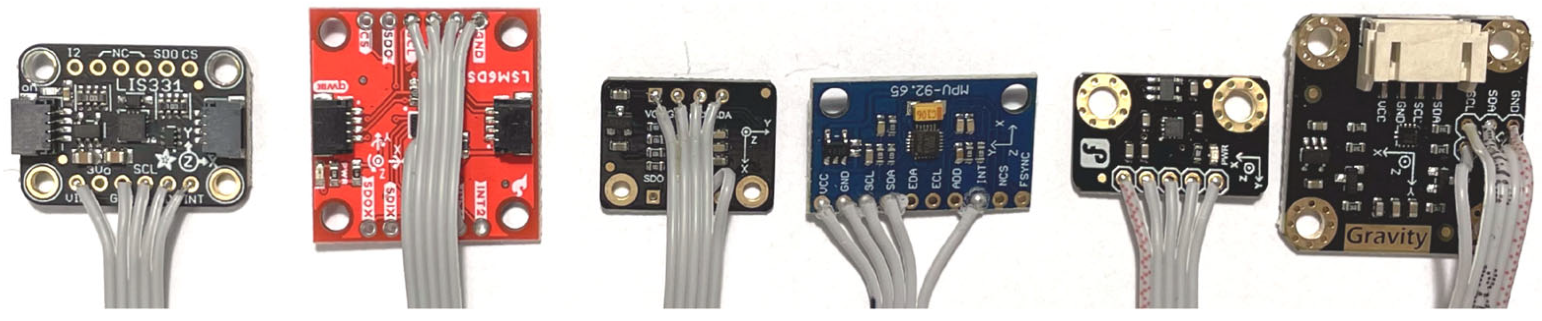
1.4.4. Surface Micromachined Capacitive Accelerometer (MEMS)

MEMS stands for microelectromechanical system, identifying any sensor manufactured using microelectronic fabrication techniques (Figure 2). These are silicon-based mechanical sensing structures that are microscopic in size. MEMS sensors can measure physical parameters such as acceleration when coupled with microelectronic circuits [18,19,20].
The inertial mass is moving, and the corresponding capacitances C1 and C2 are modified accordingly. In Figure 3, there are some examples of boards featuring MEMS sensors.
Three-axis accelerometers are commonly utilized across various sectors, including aerospace, robotics, automotive, and medical applications. These devices are essential for accurately measuring the inclination angle of objects, which is crucial in several contexts. Examples include inertial measurement systems in spacecrafts, inclination assessments in vehicles and ships, balance attitude detection in robotic systems, and limb posture monitoring in healthcare settings. Employing MEMS (microelectromechanical system) technology, three-axis accelerometers are characterized by their compact size, lightweight design, and affordability. Importantly, their use does not interfere with the mechanical operations of the objects being measured [21].

1.4.5. LVDT-Type Accelerometer

A linear variable differential transducer (LVDT) is a passive device designed for measuring displacement. It is widely regarded as the top choice for assessing various physical quantities, including displacement, pressure, force, level, and flow, in engineering applications and industrial settings [22].

1.5. The Applications of Accelerometers Used in the Industry

Accelerometer data are utilized in many applications in various activities, such as vehicle engineering, machinery industry, building and structural monitoring, navigation, handheld products, and image stabilization. The present subchapter reviewed those applications, including the areas of application and the method of data processing, to underline the wide range of applications of accelerometers.

1.5.1. Vehicle Engineering

Accelerometers measure vehicle acceleration, speed, and vibrations experienced by cars or motors. In [23], MEMS accelerometers measure vibration parameters related to different vehicle locations, such as the hood above the engine, the hood above the radiator fan, the exhaust pipe, and the dashboard. The data collected can be used for vehicle diagnostics, safety, and comfort, as shown in Figure 4.
Paper [24] investigates using accelerometers mounted on rotors to measure steady and transient vibrations induced in the rotors. A new topology and method are used to detect rotor imbalance directly from accelerometer data.
The authors of [25] propose a new filtering method for data obtained from accelerometers. This method combines an adaptive least mean squares function with a low-pass finite impulse response filter. The experiments show better signal-to-noise ratio and signal attenuation results than regular low-pass filters.
The paper’s authors [26] describe designing and optimizing a vibration-to-electric energy harvester based on a magnetic structure consisting of a levitated moving magnet and two fixed magnets, as shown in Figure 5.
In paper [27], the IPMSM structure is designed and simulated based on the ANSYS Workbench 2023 multi-physical field coupling platform to optimize the operation of the motor. This study looks at how the vibration noise from the first-order tooth harmonic occurs in space and time. To reduce this noise, we can make slots in the rotor.

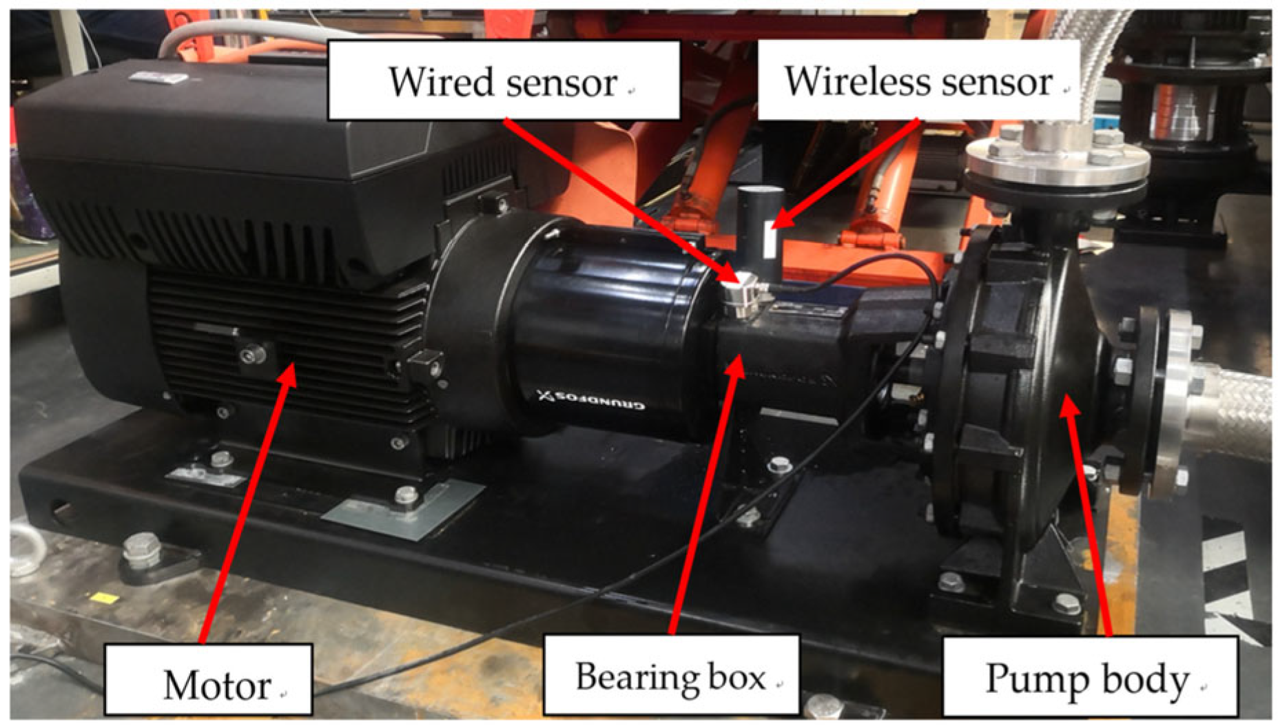
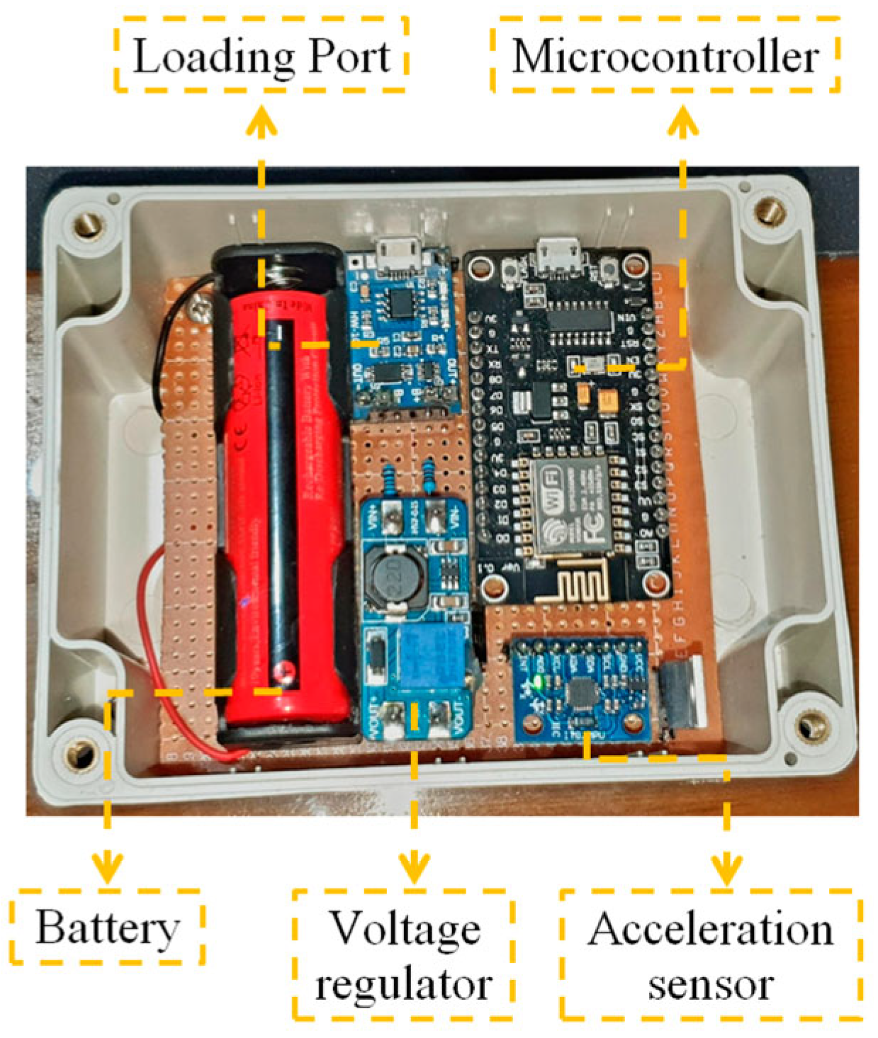
1.5.2. Machinery Industry

In industry, acceleration and vibration data are used to monitor the health of mechanical shafts and equipment bearings such as pumps, turbines, compressors, conveyors, and rollers. To monitor the state of a bearing-shaft system, the authors of [28] demonstrate semi-supervised classification for fault detection using the pattern extraction of multivariate signals. Five accelerometers are used to collect vibration data from the bearing-shaft system to establish the effectiveness of the proposed extraction method.
In [29], a method based on Symbolic Aggregate Approximation shows promising results regarding the potential use of the methodology to diagnose bearing faults. An Internet-of-things (IoT) system shown in Figure 6 was studied and designed as part of a pump monitoring application presented in [30]. Compressors, like many machines used in factories, generate vibrations and heat while they are running. It is important to keep an eye on their temperatures, because devices called piezoelectric harvesters work best when they are close to room temperature.
The study [31] herein involves acquiring vibrational data and representing these data graphically as vibration spectra.
In the paper [32], vibration control is a key challenge in oil and gas facilities using rotating machinery, particularly gas turbines. The rotor can cause instability, requiring measurements in the axial plane of the turbine. The early detection of even minor defects is crucial, as they can lead to significant increases in vibration.

1.5.3. Building and Structural Monitoring

Accelerometers measure the motion and vibration of a structure subjected to a dynamic load. This load can have various sources, such as human activity, heavy construction near the monitored structure, and weather conditions, such as wind gusts, earthquakes, and ground shocks.
The paper [33] reviews the technologies, architectures, data processing techniques, damage identification techniques, and challenges in state-of-the-art results with structural health monitoring system applications. This study shows the effectiveness and cost–benefit of wireless sensors based on MEMSs. It also highlights some difficulties these systems face with computation and real-time processing, using the system presented in Figure 7.
The reference [34] details the design of a structural health monitoring system using a wireless sensor network and a base station, with the signals diagram shown in Figure 8. The wireless network comprises 16 nodes with MEMS accelerometers and antialiasing filters.

1.5.4. Navigation

The navigation system aboard an aircraft contains accelerometers and gyroscopes. It is used with a flight computer to continuously calculate an aircraft’s position, orientation, altitude, speed, and direction of movement without visual navigation.
The paper [35] provides a detailed review of accelerometers, gyroscopes, and other sensors, all of which form the basis of inertial navigation aboard planes, drones, and UAVs, as well as different types of vehicles, such as self-driving cars.
The book [36] is a detailed manual concerning the fundamentals of navigation and inertial sensors, with accelerometers and the signal processing of accelerometer data beginning as an essential part of the manuscript.
The paper [37] presents a combination of an accelerometer and a laser ring gyroscope in designing an advanced navigation system for aircraft applications.

1.5.5. Handheld Products

Accelerometers are incorporated into many personal devices, such as phones or tablets, where they detect motion and orientation. The study [38] investigates accelerometer accuracy obtained with three smartphones. Results demonstrate that the tested smartphone accelerometers are valid and reliable for estimating accelerations.

1.5.6. Image Stabilization

Camcorders use accelerometers for image stabilization, where the information about acceleration is used to alter the image to remove the blur caused by sudden movements; both references [39,40] present such applications of image stabilization using accelerometers and different stabilization algorithms.

2. Fundamentals of Accelerometer Data

The present chapter will review the output interface of the accelerometer, the noise associated with the accelerometer’s output information, and the issues related to calibration and validation of the output information.

2.1. Output Interface

For most accelerometers, the essential connections are power and communication lines. They will communicate over an analogue, digital, or PWM connection interface.
  • The analogue interface shows accelerations through varying voltage levels, as seen in Figure 9. An analogue-to-digital converter on a microcontroller can read this value [18].
  • Digital interfaces can communicate using SPI or I2C protocols [19,20]. These tend to have more functionality and be less susceptible to noise than analogue accelerometers. The resolution of the output data can be between 10 and 16 bits and depends on the output data rate and measurement range.
  • Pulse-Width Modulation (PWM) output square waves with a fixed period and a variable duty cycle, as presented by Equation (5).
a = f t 1 , t 2
Figure 9. Analogue output voltage of accelerometer as a function of acceleration.
Asi 08 00070 g009
In Figure 10, the PWM has a period t2 and a duty cycle proportional to t1; the acceleration is proportional to these two values. The exact expression of (5) depends on each accelerometer.

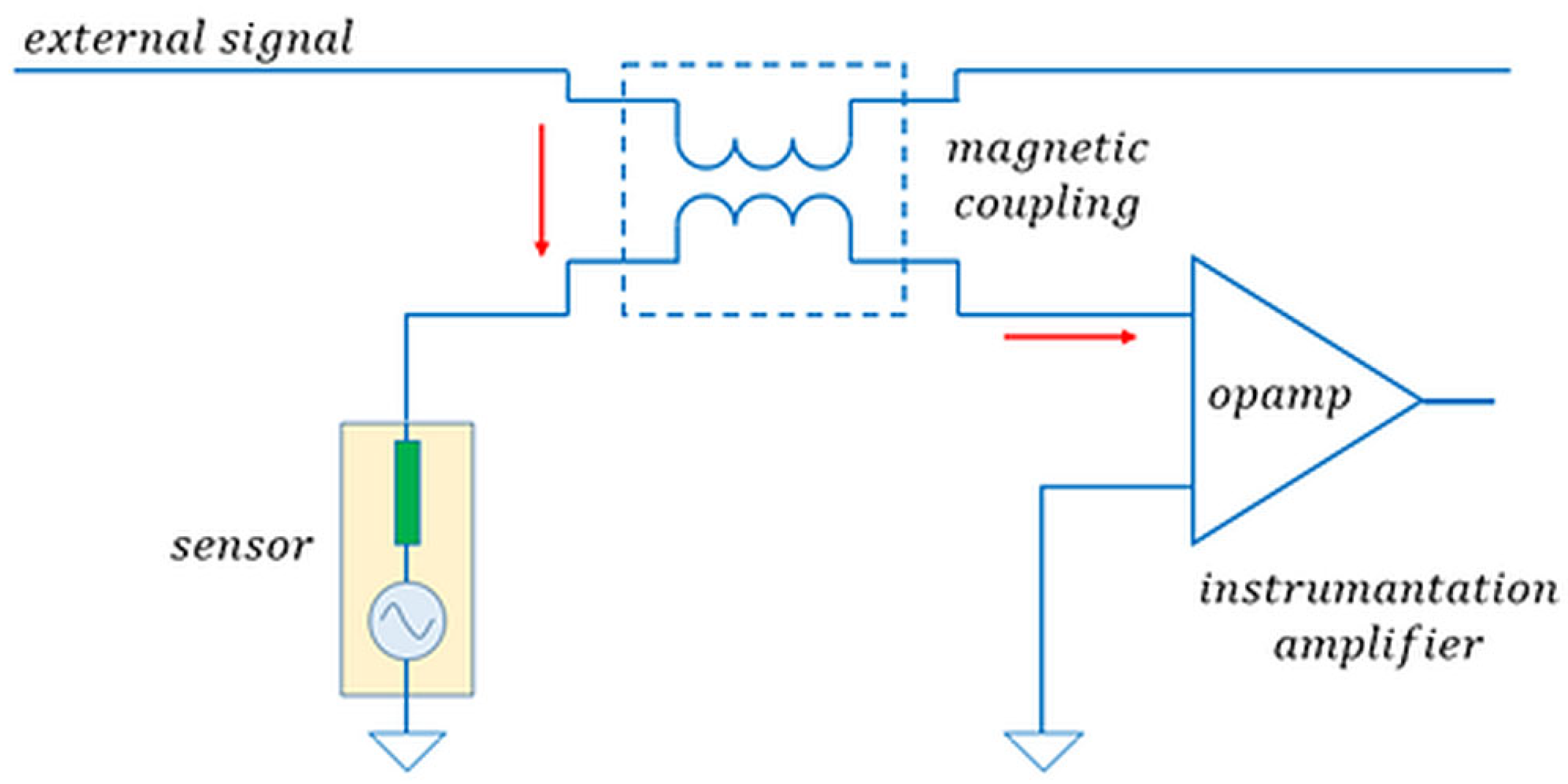
2.2. Noise and Artefacts

The analysis of practical challenges faced by railway monitoring systems is facing signal interference in complex environments and real-time requirements. The noise which affects the signal of an accelerometer has two primary sources:
  • Internal noise;
  • External noise.
Internal noise is generated by the accelerometer’s electronic and mechanical system, as analyzed for piezoelectric accelerometers in [41] or MEMS accelerometers in [42]. This type of noise is specified in the device datasheet, and the user must select an accelerometer with internal noise levels compatible with the application’s requirements.
External noise is generated from multiple sources. The user can control and limit some of this noise using proper design techniques, such as shielding and grounding. Some of the most common external noise sources come from capacitive and inductive coupling and ground loops [43], as shown in Figure 11 and Figure 12.
Capacitive coupling can be minimized by using proper shielded cables for the accelerometer, such as coaxial or twisted pair cables. Magnetic coupling is more complicated to shield. Adequate care must be taken when laying out and installing the accelerometer. The signal cables should not run close to AC power lines or magnetic devices (motors or transformers) and should be as short as possible with no loops or turns. Installing the signal cables inside grounded metal tubing can sometimes improve noise cancellation. Ground loop noise is the result of ground loops in the measuring circuit. Ground loops occur when the system has more than one ground point. Having multiple ground points that are not connected at the same voltage potential can allow current to flow through these loops and cause additional noise. The solution is to ensure all grounding is conducted at one point only.

2.3. Calibration and Validation

The calibration and recalibration of accelerometers are required to ensure that the device performs according to manufacturer specifications, that the measurements provide accurate results, and that the sensor is in a normal state of operation.
One of the more common methods to calibrate accelerometer sensors is called back-to-back calibration [44]. In this setup, the accelerometer under investigation is fixed back-to-back with a known reference accelerometer, and the combination is mounted on a vibration source. Since both sensors experience the same accelerations, the ratio of their output sensitivity will be equal to the ratio of their output level.
One downside of this method is that it can be time-consuming, as the sensors are excited at one frequency at a time.
One way to reduce the calibration time is to excite the sensors with random noise values and analyze the outputs using the Fast Fourier Transform (FFT) to compute the frequency responses and the sensitivity.

3. Signal-Processing Techniques

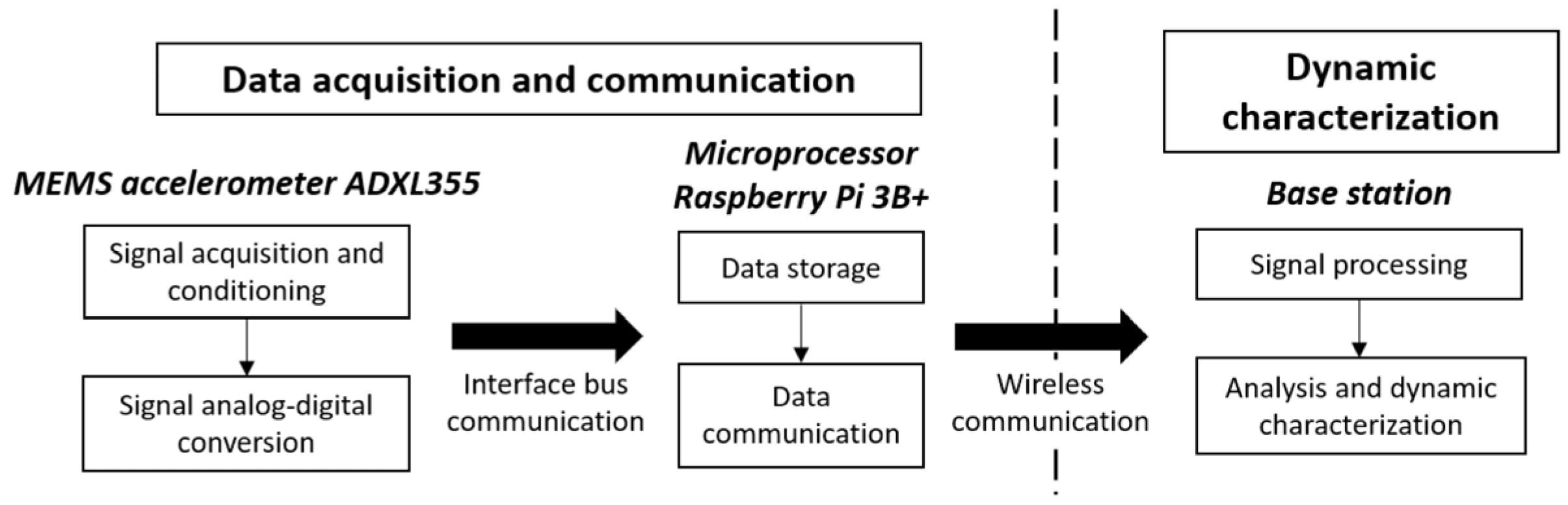
3.1. Online Data Acquisition

Regardless of the type of output an accelerometer produces, a data processing unit is necessary to automatically collect and display the readings in real-time and provide information for online processing within the control electronic unit.
This usually involves selecting a suitable microcontroller or a programmable logic controller (PLC) with the required peripheral interface for the sensor, as in [45]. Almost all microcontrollers available today can interface with accelerometer sensors since they all come equipped with analogue-to-digital converters and high-speed SPI and I2C interfaces.

3.2. Accelerometer Data Preprocessing

Because of the nature of the raw data provided by accelerometers to obtain quality data, different filtering techniques are employed to remove noise or other interference from the data signals. It is worth mentioning that these disturbances cannot be eliminated 100%, but a proper selection of the filtering method can diminish the noise without significantly affecting the relevant acceleration data.
In reference [46], a least-squares estimation using an inverse square root filtering procedure is used to obtain data estimation from an accelerometer sensor mounted inside a car. Because of the high level of interference, the data cannot be used efficiently for the onboard-embedded systems. Applying such a filter indicated a very low uncertainty of measurement, low nonlinearity, acceptable sensitivity, and a good signal-to-noise ratio, as the system was able to output at a 45 dB level.
Another filtering technique is using Kalman filters, such as the one used in the paper [47]. This filter reduced the noise affecting two accelerometers for automotive tests. The authors claim that because the noise is challenging to distinguish, such a filter allowed them to obtain optimal results and a 30 dB signal-to-noise ratio.
Other scientific research presents various filtering algorithms that can be designed using analogue or digital electronics [48]. Digital filtering is proposed in [49] and completed in a low-cost microcontroller that acquires the data. Paper [50] discusses the integration of signals from position, velocity, and acceleration sensors targeting the same subject, enhancing the observation of the subject’s kinematics by aggregating filtered versions of diverse kinematic quantities. The paper [51] introduces a novel complementary filter for manned aerial vehicles that integrates gyroscope data with readings from accelerometers and magnetic fields. The filter corrects data from IMU (Inertial Measurement Unit) and MARG (Magnetic, Angular Rate, and Gravity) sensors. The paper [52] discusses real-time noise filtering in the acquired acceleration data by MEMS devices. These algorithms can be optimal concerning specific performance indices, robust against structured and unstructured uncertainties, or may lack both optimality and robustness.

3.3. Time-Domain and Frequency-Domain Analysis

Various methods exist for analyzing accelerometer data, such as time-domain or frequency-domain analysis. The paper [53] studies the time-frequency analysis of data.
The time-domain features considered by the authors are the following:
  • The zero-crossing rate is a simple, cost-effective way to compare patterns in two sets of time-series measurements. It is a feature that is useful in analyzing noise corruption.
  • Correlation coefficients are a useful tool to check if two time-series readings are similar;
  • Cross correlations functionto measure the extent of the offset between two time-series measurements;
  • The signal’s RMS and peak-to-peak values are used to set alarms on specific thresholds based on the application’s particular needs.
The characteristics in the frequency domain are as follows:
  • Maxima and energy are used to compare dominant frequencies in measurements, while the spectral energy of sensor readings reflects their spectral structure.
  • The correlation coefficients for both FFT and STFT are useful for examining how frequencies shift over time, serving as an important measure of correlation;
  • Spectral roll-off is a feature that looks at the frequency. It only considers the Fourier transformation of acceleration vectors;
  • The spectral centroid shows the average location of the “center of gravity” of a vibration’s spectrum. It is similar to the “first n-maxima” and helps us to understand where the main energy of the vibration is located;
  • Spectral flux measures the rate of change in the power spectrum.
Their study reveals that features extracted from the absolute values of the measurements are more robust against noise and calibration errors and that the frequency-domain features are the coefficients of the absolute values of the short-time Fourier transformation.
The authors [54] present the analysis of vibration signals using the Fast Fourier Transform and show how the frequency spectrum of vibrating sources gives information about the vibration level present.

3.4. Wavelet Transform

A wavelet transform (WT) effectively decomposes a signal into basis functions that are derived from a mother wavelet through processes of contraction, expansion, and translation. This method provides an opportunity for the in-depth analysis of the signal across different scales and positions, allowing for an enhanced understanding and interpretation of the data [55]. Wavelet compression is a data compression technique ideal for images, and sometimes for video and audio. Its goal is to minimize the file size, and it can be either lossless or lossy. Wavelet transforms effectively represent transients—like percussion sounds in audio or high-frequency components in images, such as stars in a night sky. This allows for a more efficient representation of these elements compared to other methods, like the discrete cosine transform.
This technique is applied to accelerometer data processing, as in [56], where the device measures cardiac activity from the chest using an accelerometer.
The paper [57] introduces a novel feature called wavelet-AR for recognizing human activities using triaxial acceleration signals. The authors employed wavelet transform techniques to break down the raw accelerometer data, deriving decomposed signals that effectively distinguish between various activities. Their findings demonstrate that wavelet-AR achieves significant differentiation among different types of human activities, presenting an innovative option for activity recognition.

4. Examples of Accelerometers Used in Rail Vehicle Systems

Accelerometers are being investigated as a possible solution for detecting above-normal vibrations experienced by railway cars or tracks. Continuous studies are carried out to improve detection methods and signal analysis algorithms, which provide information about the health of the rail tracks and rail cars that can be used for predictive and corrective maintenance, thus improving the safety and comfort of the railroad.
In [58], the authors present a method for the early detection of a rail track defect called a squat caused by short wavelength rotational contact. Their method involves mounting three-axis accelerometers on the axle box, and the algorithm used to process the sensor data is based on a wavelet spectrum analysis. One of the findings of this paper was that accelerometer longitudinal measurements were more effective in detecting the squat defect than vertical measurements. The wavelet analysis identified the frequency band of the squat signals to be between 600 and 800 Hz, depending on the rail section, either joints, welds, or hanging sleepers. The proposed method was tested on a section of a high-speed line, and the results of the experiments showed a detection rate of 88%. The primary location where the squat defect was detected was at the rail welds and rail joint section. The system presented allows safety inspections to be performed at shorter intervals than regular inspections without using special inspection vehicles.
The study [59] presents some issues when implementing MEMS accelerometers mounted on the sprung parts of the railcar bogie and the axle boxes. Different sensor positions and different sensor configurations have been investigated. The configuration of the sensors depends on the accuracy requirements, and it is suggested that sensors with different characteristics should be used to create a virtual accelerometer out of this mini-sensor network. Analyzing the signals requires algorithms such as the wavelet transform or the Fast Fourier Transform.
The authors of [60] investigate the possibility of using an artificial intelligence algorithm to detect rail track defects based on accelerometer data mounted on running trains. Their method measures the axle box signals from eight onboard accelerometers, as shown in Figure 13.
The AI algorithm uses an unsupervised learning approach to detect and track irregularities. The detection comprises four stages:
  • feature extraction using an autoregressive method;
  • feature normalization;
  • data fusion;
  • damage detection.
SIMPACK simulations with model parameters based on an authentic freight wagon were carried out. The results showed that the detection accuracy of the damaged longitudinal level, lateral alignment, cross-level, and twist is greater than or equal to 94%. The developed approach can be used for the early warning of passenger comfort and unbalanced loads affecting freight vehicles.
A comprehensive study was performed in [61] regarding drive-by methodologies for collecting data on track irregularities, rail conditions, and rail supporting elements, including field experiments as shown in Figure 14. The authors conclude that drive-by methodologies have several promising future applications. These include track maintenance optimization, proactive fault detection, predictive maintenance, track performance evaluation, vehicle health monitoring, and data-driven decision-making.
In [62], a procedure to monitor a rail track defect called rail corrugation is presented. This defect manifests as a quasi-periodic irregularity of the track’s surface. It is a critical problem for urban railways because it induces ground vibrations in buildings near the rail track. Typical mitigation involves grinding the rail using a dedicated service vehicle, which is not the most efficient method, as it can only be performed when vehicles are not running on the tracks. The proposed procedure is based on measurements obtained from six single-axis accelerometers mounted on the axle box of the tram, as shown in Figure 15.
The rail irregularity is obtained by the frequency-domain analysis of the measured signals. The practical testing was performed by equipping a rail vehicle with the proposed system and collecting data during a running day. The system was used to estimate the power spectrum of the rail irregularity in terms of roughness level on a track section of a subway line between two stations. The results indicate the corrugation on the low rail of both curves in the 100–300 mm wavelength band, which was confirmed by in-field observations. The proposed methodology can thus be used to continuously monitor rail corrugation at service speeds.
Another example of acceleration information used in railway track monitoring is in the paper [63]. MEMS sensors located on the bogie and car body provide valuable insights into track alignment. These data are further analyzed through a mathematical model and frequency response analysis. Both simulation and field results demonstrate the efficacy of the proposed system. To optimize the irregularity values obtained from accelerometers installed in the axle box and bogie, the differential evolution (DE) algorithm is employed. Simulations are conducted at two different train speeds, allowing for a comparison between traditional track geometry measurements and the new DE method. The findings highlight the effectiveness of this innovative approach.
In the UK, the Rail Safety and Standards Board (RSSB) funded a study [64] to create a cost-effective solution for the detection of track voids and other track defects using an in-service multi-train system. This study involved the development of an algorithm based on a state machine design methodology, which was subsequently tested on experimental data. The system consists of MEMS sensors that measure the acceleration of the rail vehicles, and FFT analysis is used to detect the RMS values of the vibration frequency spectrum. The authors claim that the results show a good agreement with reported track faults; thus, the system can provide a low-cost recorder of rail track defects.
The study in [65] presents an algorithm to detect hunting oscillations in railway vehicles using accelerometer sensors. According to the authors, there are inherent hunting oscillations because the wheel’s profile is a conical shape. These oscillations appear at different speeds, which are determined by the wheel profile, rail profile, and the vehicle’s dynamics. These oscillations are a source of discomfort and instability during riding and can increase the risk of derailment. The algorithm in the paper is based on the lateral and longitudinal accelerations of the railway bogie, and data are obtained by mounting three-axis accelerometers above the axle boxes. The data are used to calculate an Index of Hunting Oscillation. Simulations were carried out using the SIMPACK 2024 software program to validate their algorithm, while the practical validation was conducted on data acquired from actual bogie dynamic tests. The results indicate a detection accuracy of 85%. This result is lower than the average accuracy of other methods; however, the complexity and computational effort of the proposed method are lower than those of different methods. The authors plan to improve the performance of the proposed algorithm.
The main constraints of conventional rail vehicle vibration monitoring systems pertain to their substantial volume, intricate wiring configuration, and restricted operational range. In the paper [66], a PHM (Prognostics Health Management) vibration monitoring system for rail vehicles is proposed based on the Internet of things (IoT). This system can transmit wireless data, exhibits a high sampling rate, and employs IoT technology to reduce system costs. The MESH wireless intelligent network transmits data collected by edge node sensors to the central node and subsequently uploads these data to the cloud. The experimental test of the system took place in a subway, where the collection nodes were distributed across multiple locations within the rail vehicle compartment. The reliability of the encapsulated node collection was validated based on the data characteristics collected on-site.
The detection of train arrivals at track maintenance sites is necessary to ensure worker safety. In [67], a new method for train detection is proposed using a sensor on the track. Using a well-designed system to collect data and a good method to process these data, we can detect a train approaching from about 1 km away from where the sensors are set up. Several tests were performed on real train tracks, and these tests showed that this approach is very reliable. A particular range of vibration frequencies has been identified as the most effective for tracking when a train is arriving. An alarm is triggered when the continuously measuring vibrations surpass a specific value.
The article [68] presents the development and testing of a self-contained railway track monitoring system that fuses signals from a laser Doppler vibrometer (LDV), axle box accelerometers (ABAs), GPS, and a video camera for anomaly detection in railway tracks. The multi-signal-processing method is proposed to obtain train-track vibrations with train position and speed. Multiple signals are extracted from the fuse, including an impact index, a resonance index, and an interpretable anomaly detection strategy. Additionally, the system contains positioning, speed estimation, and speed normalization processes; thus, it is considered more self-contained. The normalization eliminates the speed-dependent characteristics of the power spectral density (PSD), providing adaptability to varying train speeds.
Technologies for detecting track irregularities are crucial for ensuring the safety and comfort of high-speed trains. One innovative method involves onboard equipment that uses a special algorithm to identify track issues [69]. This system monitors the railway condition and assists with timely maintenance. The setup includes devices for data collection, synchronization, and processing. By analyzing vibrations from the train’s axle box, the algorithm effectively identifies irregularities in the track’s alignment. This technology has been tested on various high-speed rail lines, proving to be highly accurate. Overall, it helps maintain smooth and safe train operations by detecting potential track problems early on.
In [70], the text discusses a method used to understand how trains interact with railway tracks at crossings. This approach combines measurements taken directly from train axle boxes with tests using accelerometers to evaluate how different factors affect the train’s behavior. These factors include the speed of the train, the direction in which it is moving (whether it is approaching or leaving), where the sensors are placed (either on the front or back wheels of a train car), and how the track itself responds naturally.
Railway transport safety is directly connected to the condition of railway tracks and wheel surfaces. Irregularities of a railway track lead to various defects in the railway; thus, it is necessary to estimate the length of short and impulse irregularities. In addition, conducting a joint analysis of vibration acceleration signals recorded by accelerometers to study the types and sizes of railway track irregularities is essential. Components containing information about the railway track bogie detected oscillations were concentrated in the low-frequency domain. The paper [71] presents several algorithms based on the continuous wavelet transform. The continuous wavelet transform provides an appropriate resolution in the low-frequency domain for localizing the components and visualizing defects.
The idea is to examine the vibrations caused by uneven rail tracks to gather information about the condition of the rails. A recent study [72] used a special method called the maximal overlap discrete wavelet packet transform (MODWPT) to analyze data collected from small sensors during tram rides. This method helps break down the vibration signals into several parts without losing any important details, which is different from other techniques that can lose some information when they analyze signals. By using this approach, researchers can gain a better understanding of how the tracks are holding up.
In the paper [73], an online rail deformation monitoring system is presented for implementation on moving trains to report any deformation beyond the threshold in a timely manner. The system uses a simple method to detect any bending or distortion in railway tracks. It does this by using three sensors that measure acceleration, which are placed on the train. The proposed method was tested on a ZT-3 type train, and the results were compared with those obtained from the GJ-4 reference inspection car type. The method can tell the difference between vibrations caused by changes in the train tracks and those caused by the train moving itself. It does this by examining the sideways movements of the train’s crossbeam and the wheels.
Reference [74] presents the modelling and fault diagnosis of railroad jointless tracks based on the piecewise equivalent ballast resistance. The authors use a two-port network and transmission line theory to model all the components.

5. Guide for Choosing a Correct Accelerometer

When recommending the best accelerometer in terms of cost and performance for use in the rail vehicle industry, we have to consider the following considerations:

5.1. Technology

The first step in technology selection involves determining the measurement type. There are three popular technologies that people use to measure acceleration.
  • Piezoelectric accelerometers are useful tools for measuring shocks and vibrations. They can detect a wide range of frequencies, from very low (a few times per second) to quite high (up to 30,000 times per second). This makes them great for capturing different types of movements and impacts.
  • Piezoresistive accelerometers are sensitive devices that measure changes in movement. They are particularly good for detecting sudden shocks and can effectively monitor changes over long periods of time. These accelerometers can capture a wide range of motion, but their ability to detect very low frequencies, including steady situations, diminishes over time.
  • Variable capacitance accelerometers, also known as VC or MEMS accelerometers, are a type of technology used to measure movement and vibrations. They are known for being very sensitive, which allows them to detect subtle changes, and they perform well even when temperatures vary. This makes them ideal for monitoring slow movements and steady changes in acceleration.
To effectively identify different kinds of irregular movements, it is important to use the right accelerometer along with some noise reduction techniques and digital processing. This combination helps in accurately measuring and analyzing data related to motion.

5.2. Sensitivity and Resolution

An accelerometer is a device that measures movement or acceleration and transforms that motion into an electrical signal. When it outputs data, they are often measured in millivolts per “g”, which refers to the gravitational force we experience on Earth. For a charge-mode accelerometer, the measurement is given in pC per “g”. These devices come in various sensitivities, meaning some are better at detecting small movements than others. The best choice of sensitivity will depend on how strong or weak the motion you want to measure is.
When dealing with small vibrations, using a very sensitive accelerometer is important. This type of device can pick up signals that are much clearer and stronger than the background noise produced by other electronic parts. For instance, if we expect the vibrations to be very slight (like 0.1 g) and our accelerometer can produce a 10 millivolt (mV) signal for every g, then the output would only be 1 mV. This might not be enough to stand out from the noise, so using an accelerometer with even greater sensitivity would be a good idea.
Additionally, the concept of resolution is important to understand. This basically refers to the smallest change in vibration that the accelerometer can reliably detect, and it depends on the device’s noise level. A lower noise level allows for the better detection of tiny signals.

5.3. Standards Applicable in the Field of Rail Vehicle Monitoring

The standards reviewed in this subchapter apply to devices that monitor the rail vehicle’s safety and the passenger’s comfort, including accelerometers.
UIC—International Union of Railways is using the online portal to publish standards, regulations, and papers regarding all types of tests for safety and comfort using accelerometers. A dedicated study can be found at [75].
IEC 60077-2, Railway applications—Electric equipment for rolling stock—Part 2: Electrotechnical components—General rules [76] specifies the general conditions and requirements for all electric equipment installed in power circuits, auxiliary circuits, control and indicating circuits, etc., on railway rolling stocks.
EN 50155:2021 Railway applications—Rolling stock—Electronic equipment [77] is a standard that impacts the design, manufacturing, and maintenance of electronic equipment for railway vehicles. It outlines the requirements for electronic systems to ensure they can withstand the harsh conditions of railway environments, including temperature variations, humidity, shock, and vibration.
EN 12299:2024 is a standard that defines the ride comfort for passengers of railway vehicles [78]. This document provides methods for quantifying passenger ride comfort in a rail vehicle. The methods aim to quantify the effects of vehicle body motions on ride comfort and to make the assessment of passenger comfort predictable, repeatable, objective, and meaningful.
IEC 62974-1:2024 Monitoring and measuring systems used for data collection, aggregation and analysis—Part 1: Device requirements [79] provides the requirements for the design and construction of data used in electronic devices, including the “management of digital and/or analogue input(s) or output(s)” and “Communication connectivity features”.
IEC 60571:2012 Railway applications—Electronic equipment used on rolling stock [80], covers the conditions of the operation, design, construction, and testing of electronic equipment, as well as basic hardware and software requirements for all electronic equipment installed on rail vehicles related to control, regulation, protection, and supply.
ISO 16063-32:2016 Methods for the calibration of vibration and shock transducers Part 32: Resonance testing—Testing the frequency and the phase response of accelerometers by means of shock excitation [81] lays down detailed specifications for instruments and procedures for testing the frequency and phase response of accelerometers using shock excitation. It applies to accelerometers of the piezoelectric, piezoresistive, and variable capacitance types, with a damping ratio less than critical and in the frequency range up to 150 kHz.
More rail vehicle equipment standards are available for online purchase.

6. Conclusions

The present study aimed to analyze the theory of measuring acceleration, identify the available solutions for accelerometers, and provide information for selecting the best accelerometer for railway coaches to supervise the safety and comfort of passengers.
A coach passing over rail defects creates accelerations and vibration frequencies in the range of 4 Hz to 1 kHz and a maximum of 2−4 g acceleration; as such, an accelerometer needs to be selected to detect triaxial motion with a sufficiently high bandwidth, resolution, and accuracy to capture all these phenomena.
Modern MEMS capacitance accelerometers have a high sensitivity, a wide measuring range, and high-temperature stability, making them suitable for use on railroad cars.
In Table 1, we compared a few accelerometers which support railway applications.
All the above accelerometers are suitable for use in railway vehicles to sense track irregularities, wind influence, and failures of the coach suspensions. The collected data can also monitor the passenger’s comfort and assist the rail operators in taking action.

7. Future Directions

Our team’s future work will consider using an online detection tool for the railway coach frame acceleration and signalization of the peak values using the train intercom to the driver and static diagnosis systems.
The data recorded with accelerometers can be analyzed using machine learning methods to create a rapid and precise online diagnosis system.

Author Contributions

Conceptualization, E.T. and I.V.; methodology, I.V.; formal analysis, G.P.; investigation, I.V.; resources, D.L, C.D., and N.T.; writing—original draft preparation, I.V.; writing—review and editing, I.V. and E.T.; visualization, C.D. and D.L.; supervision, G.P. and F.D. All authors have read and agreed to the published version of the manuscript.

Funding

This work was supported by a grant from the Romanian Ministry of Research Innovation and Digitization, CCCDI—UEFISCDI, project number 22PTE/2025, within PNCDI IV.

Data Availability Statement

No new data were created.

Conflicts of Interest

Author Florian Drăghici was employed by the company Tehmin-Brașov. The remaining authors declare that the research was conducted in the absence of any commercial or financial relationships that could be construed as a potential conflict of interest.

References

  1. Denishev, K.H.; Petrova, M.R. Accelerometer design. In Proceedings of the ELECTRONICS’ 2007, Sozopol, Bulgaria, 19–21 September 2007. [Google Scholar]
  2. Eren, H. Acceleration, Vibration, and Shock Measurement. In The Measurement, Instrumentation, and Sensors Handbook—Spatial, Mechanical, Thermal, and Radiation Measurement; CRC Press: Boca Raton, FL, USA, January 2014. [Google Scholar]
  3. Serridge, M.; Licht, T. Piezoelectric Accelerometers and Vibration Preamplifiers: Theory and Application Handbook; Brüel & Kjær: Nærum, Denmark, 1986; 151p. [Google Scholar]
  4. Wagner, J.; Burgemeister, J. Piezoelectric Accelerometers: Theory and Application, 7th ed.; Manfred Weber Metra Mess- und Frequenztechnik in Radebeul e.K.: Radebeul, Germany, 2021. [Google Scholar]
  5. Constantinescu, F.; Gheorghe, A.; Nitescu, M. A Capacitive Accelerometer Model. Rev. Roum. Sci. Tech.—Ser. Électrotech. Énerg. 2013, 58, 163–172. [Google Scholar]
  6. Voldman, J. Design and Fabrication of Microelectromechanical Devices; Course Materials for 6.777J/2.372J; MIT OpenCourseWare. 2007. Available online: http://ocw.mit.edu/ (accessed on 10 April 2025).
  7. Mahdavi, N.; Suske, M. Inertial Grade Laser Accelerometer–Practicability and Basic Experiments. In Proceedings of the XVII IMEKO World Congress, Dubrovnik, Croatia, 22–27 June 2003. [Google Scholar]
  8. Qian, L.; Li, D. Use of Magnetic Fluid in Accelerometers. J. Sens. 2014, 2014, 375623. [Google Scholar] [CrossRef]
  9. Ju, D.-Y.; Tabata, K. Development and Optimization of Design of an Acceleration Sensor Using Ferrofluid. Sens. Mater. 2008, 20, 409–416. [Google Scholar]
  10. Lopez-Hignera, J.-M.; Morante, M.A.; Cobo, A. Simple low-frequency optical fiber accelerometer with large rotating machine monitoring applications. J. Light. Technol. 1997, 15, 1120–1130. [Google Scholar] [CrossRef]
  11. Casas-Ramos, M.A.; Castillo-Barrera, L.G.; Sandoval-Romero, G.E. Optical accelerometer for seismic measurement. Vibroeng. Procedia 2018, 21, 38–41. [Google Scholar] [CrossRef]
  12. Baldwin, C.S.; Niemczuk, J.B.; Kiddy, J.S.; Salter, T.J. Review of Fiber Optic Accelerometers. Available online: https://api.semanticscholar.org/CorpusID:180260894 (accessed on 10 April 2025).
  13. Shevchenko, S.; Kukaev, A.; Khivrich, M.; Lukyanov, D. Surface-Acoustic-Wave Sensor Design for Acceleration Measurement. Sensors 2018, 18, 2301. [Google Scholar] [CrossRef]
  14. Coyte, J.L.; Stirling, D.; Du, H.; Ros, M. Seated Whole-Body Vibration Analysis, Technologies, and Modeling: A Survey. IEEE Trans. Syst. Man Cybern. Syst. 2016, 46, 725–739. [Google Scholar] [CrossRef]
  15. Prakash, A.; Rajamohan, V.; Sudhagar, E. Design and Analysis of a Shear Mode IEPE Accelerometer. Int. J. Pure Appl. Math. 2018, 118, 4157–4164. [Google Scholar]
  16. National Instruments. Strain Gauge Measurement—A Tutorial, Application Note 078. August 1998. Available online: http://elektron.pol.lublin.pl/elekp/ap_notes/ni_an078_strain_gauge_meas.pdf (accessed on 11 March 2025).
  17. Salzano, C. Dynamic Strain Sensors and Accelerometers for Structural Testing: Cases of Measurements on a Civil Structure and on the GVT of an F-16 Aircraft. In IOMAC 2024; Lecture Notes in Civil Engineering; Springer: Cham, Switzerland, 2024; Volume 514. [Google Scholar] [CrossRef]
  18. Jérôme Laine, J.; Mougenot, D. A high-sensitivity MEMS-based accelerometer. Lead. Edge 2014, 33, 1210–1308. [Google Scholar] [CrossRef]
  19. Srokosz, P.E.; Daniszewska, E.; Banach, J.; Śmieja, M. In-Depth Analysis of Low-Cost Micro Electromechanical System (MEMS) Accelerometers in the Context of Low Frequencies and Vibration Amplitudes. Sensors 2024, 24, 6877. [Google Scholar] [CrossRef]
  20. Büsching, F.; Kulau, U.; Gietzelt, M.; Wolf, L. Comparison and validation of capacitive accelerometers for health care applications. Comput. Methods Programs Biomed. 2012, 106, 79–88. [Google Scholar] [CrossRef] [PubMed]
  21. Bouten, C.V.C.; Koekkoek, K.T.M.; Verduin, M.; Kodde, R.; Janssen, J.D. A triaxial accelerometer and portable data processing unit for the assessment of daily physical activity. IEEE Trans. Biomed. Eng. 1997, 44, 136–147. [Google Scholar] [CrossRef] [PubMed]
  22. Joshi, S.; Harle, S.M. Linear Variable Differential Transducer (LVDT) & Its Applications in Civil Engineering. Int. J. Transp. Eng. Technol. 2017, 3, 62–66. [Google Scholar] [CrossRef]
  23. Ahmed, H.E.; Sahandabadi, S.; Bhawya; Ahamed, M.J. Application of MEMS Accelerometers in Dynamic Vibration Monitoring of a Vehicle. Micromachines 2023, 14, 923. [Google Scholar] [CrossRef]
  24. Jiménez, S.; Cole, M.O.T.; Keogh, P.S. Vibration sensing in smart machine rotors using internal MEMS accelerometers. J. Sound Vib. 2016, 377, 58–75. [Google Scholar] [CrossRef]
  25. Suwandi, B.; Kitasuka, T.; Aritsugi, M. Vehicle Vibration Error Compensation on IMU-accelerometer Sensor Using Adaptive Filter and Low-pass Filter Approaches. J. Inf. Process. 2019, 27, 33–40. [Google Scholar] [CrossRef]
  26. Olaru, R.; Ghercă, R.; Petrescu, C. Analysis and Design of A Vibration Energy Harvester Using Permanent Magnets. Rev. Roum. Sci. Tech.—Électrotech. Énerg. 2014, 59, 131–140. [Google Scholar]
  27. Chen, X.; Ma, L.; Zhang, L.; Zhang, C. Vibration and Noise Optimization of Rotor Structure of Permanent Magnet Synchronous Motor for Vehicles. Electroteh. Electron. Autom. (EEA) 2023, 71, 1–9. [Google Scholar] [CrossRef]
  28. Baek, S.; Yoon, H.S.; Kim, D.Y. Abnormal vibration detection in the bearing-shaft system via semi-supervised classification of accelerometer signal patterns. Procedia Manuf. 2020, 51, 316–323. [Google Scholar] [CrossRef]
  29. Georgoulas, G.; Karvelis, P.; Loutas, T.; Stylios, C.D. Rolling element bearings diagnostics using the Symbolic Aggregate approXimation. Mech. Syst. Signal Process. 2015, 60–61, 229–242. [Google Scholar] [CrossRef]
  30. Chen, L.; Wei, L.; Wang, Y.; Wang, J.; Li, W. Monitoring and Predictive Maintenance of Centrifugal Pumps Based on Smart, Sensors. Sensors 2022, 22, 2106. [Google Scholar] [CrossRef] [PubMed]
  31. Săvescu, C.; Petrescu, V.; Comeagă, D.; Vlăducă, I.; Nechifor, C.; Niculescu, F. Vibration Analysis of a Twin-Screw Compressor as a Potential Source for Piezoelectric Energy Harvesting. Rev. Roum. Sci. Tech.—Électrotech. Énerg. 2023, 68, 253–258. [Google Scholar] [CrossRef]
  32. Ben Rahmoune, M.; Iratni, A.; Hafaifa, A.; Colak, I. Gas Turbine Vibrations Detection and Identification based on Dynamic Artificial Neural Networks. Electroteh. Electron. Autom. (EEA) 2023, 71, 19–27. [Google Scholar] [CrossRef]
  33. López-Castro, B.; Haro-Baez, A.G.; Arcos-Aviles, D.; Barreno-Riera, M.; Landázuri-Avilés, B. A Systematic Review of Structural Health Monitoring Systems to Strengthen Post-Earthquake Assessment Procedures. Sensors 2022, 22, 9206. [Google Scholar] [CrossRef] [PubMed]
  34. Caballero-Russi, D.; Ortiz, A.R.; Guzmán, A.; Canchila, C. Design and Validation of a Low-Cost Structural Health Monitoring System for Dynamic Characterization of Structures. Appl. Sci. 2022, 12, 2807. [Google Scholar] [CrossRef]
  35. El-Sheimy, N.; Youssef, A. Inertial sensors technologies for navigation applications: State of the art and future trends. Satell. Navig. 2020, 1, 2. [Google Scholar] [CrossRef]
  36. Bose, A.; Bhat, K.N.; Kurian, T. Fundamentals of Navigation and Inertial Sensors; Eastern Economy Edition; PHI Learning: Delhi, India, 2014; 312p, ISBN 9788120348592. [Google Scholar]
  37. Satheesh Reddy, G.; Saraswat, V.K. Advanced Navigation System for Aircraft Applications. Def. Sci. J. 2013, 63, 131–137. [Google Scholar] [CrossRef]
  38. Grouios, G.; Ziagkas, E.; Loukovitis, A.; Chatzinikolaou, K.; Koidou, E. Accelerometers in Our Pocket: Does Smartphone Accelerometer Technology Provide Accurate Data? Sensors 2023, 23, 192. [Google Scholar] [CrossRef]
  39. Quicklogic. Available online: https://cdn.sparkfun.com/assets/7/a/c/c/e/QL-EOS-S3-Ultra-Low-Power-multicore-MCU-Datasheet-v3_3d.pdf (accessed on 11 March 2025).
  40. Drahanský, M.; Orság, F.; Hanáček, P. Accelerometer Based Digital Video Stabilization for Security Surveillance Systems. In Security Technology. SecTech 2009; Ślęzak, D., Kim, T., Fang, W.C., Arnett, K.P., Eds.; Communications in Computer and Information Science; Springer: Berlin/Heidelberg, Germany, 2009; Volume 58. [Google Scholar] [CrossRef]
  41. Levinzon, F. Practical Considerations of Accelerometers Noise; Endevco Sensing Systems, Technical Paper 324. Available online: https://endevco.com/contentStore/mktgContent/endevco/dlm_uploads/2019/02/Endevco_TP324_REVISED.pdf (accessed on 23 May 2025).
  42. Mohd-Yasin, F.; Korman, C.E.; Nagel, D.J. Measurement of noise characteristics of MEMS accelerometers. Solid-State Electron. 2003, 47, 357–360. [Google Scholar] [CrossRef]
  43. Brüel & Kjær Book. Measuring Vibration. 1982. Available online: https://www.bksv.com/media/doc/br0094.pdf (accessed on 23 May 2025).
  44. Brüel & Kjær. Back to Back Calibration of Accelerometers Using FFT Analysis for Sensitivity Comparison at 800 Frequencies. Application Note BO0237. Available online: https://www.bksv.com/media/doc/BO0237.pdf (accessed on 23 May 2025).
  45. Payne, B.F. The Application of Back-to-Back Accelerometers to Precision Vibration Measurements. J. Res. Natl. Bur. Stand. 1983, 88, 171–174. [Google Scholar] [CrossRef] [PubMed] [PubMed Central]
  46. Hernandez, W. Optimal estimation of the relevant information coming from a rollover sensor placed in a car under performance tests. Measurement 2008, 41, 20–31. [Google Scholar] [CrossRef]
  47. Hernández, W. Improving the Responses of Several Accelerometers Used in a Car under Performance Tests by Using Kalman Filtering. Sensors 2001, 1, 38–52. [Google Scholar] [CrossRef]
  48. Doyle, J. Robust and optimal control. In Proceedings of the 35th IEEE Conference on Decision and Control, Kobe, Japan, 13 December 1996; Volume 2, pp. 1595–1598. [Google Scholar] [CrossRef]
  49. Sheikhaleh, A.; Abedi, K.; Jafari, K. An Optical MEMS Accelerometer Based on a Two-Dimensional Photonic Crystal Add-Drop Filter. J. Light. Technol. 2017, 35, 3029–3034. [Google Scholar] [CrossRef]
  50. D’Arco, M.; Guerritore, M. Multi-Sensor Data Fusion Approach for Kinematic Quantities. Energies 2022, 15, 2916. [Google Scholar] [CrossRef]
  51. Valenti, R.G.; Dryanovski, I.; Xiao, J. Keeping a Good Attitude: A Quaternion-Based Orientation Filter for IMUs and MARGs. Sensors 2015, 15, 19302–19330. [Google Scholar] [CrossRef]
  52. Chikhalikar, S.; Khandekar, O.; Bhattacharya, C. Design of Real-Time Acquisition and Filtering for MEMS-based Accelerometer Data in Microcontroller. In Proceedings of the 2018 IEEE Electron Devices Kolkata Conference (EDKCON), Kolkata, India, 24–25 November 2018; pp. 15–18. [Google Scholar] [CrossRef]
  53. Dargie, W. Analysis of Time and Frequency Domain Features of Accelerometer Measurements. In Proceedings of the 18th International Conference on Computer Communications and Networks, San Francisco, CA, USA, 3–6 August 2009; pp. 1–6. [Google Scholar] [CrossRef]
  54. Kumari, S. Vibration Measurement Using Accelerometer Sensor and Fast Fourier Transform. In Trends in Wireless Communication and Information Security; Chakraborty, M., Jha, R.K., Balas, V.E., Sur, S.N., Kandar, D., Eds.; Lecture Notes in Electrical Engineering; Springer: Singapore, 2021; Volume 740. [Google Scholar] [CrossRef]
  55. Chui, C.K. An Introduction to Wavelets; Academic Press: San Diego, CA, USA, 1992; ISBN 0-12-174584-8. [Google Scholar]
  56. Ferdinando, H.; Seppälä, E.; Myllylä, T. Discrete Wavelet Transforms-Based Analysis of Accelerometer Signals for Continuous Human Cardiac Monitoring. Appl. Sci. 2021, 11, 12072. [Google Scholar] [CrossRef]
  57. He, Z. Activity recognition from accelerometer signals based on Wavelet-AR model. In Proceedings of the 2010 IEEE International Conference on Progress in Informatics and Computing, Shanghai, China, 10–12 December 2010; pp. 499–502. [Google Scholar] [CrossRef]
  58. Cho, H.; Park, J.; Park, K. Analysis of Axial Acceleration for the Detection of Rail Squats in High-Speed Railways. CivilEng 2023, 4, 1143–1156. [Google Scholar] [CrossRef]
  59. Bolshakova, A.; Podgornaya, L.; Tkachenko, A.; Larionov, D.; Shalymov, R.; Boronachin, A.; Bokhman, E. Specific Features of Using Micromechanical Accelerometers for Monitoring Short and Impact Irregularities of the Railway Track. In Proceedings of the 2021 28th Saint Petersburg International Conference on Integrated Navigation Systems (ICINS), Saint Petersburg, Russia, 31 May–2 June 2021; pp. 1–3. [Google Scholar] [CrossRef]
  60. Traquinho, N.; Vale, C.; Ribeiro, D.; Meixedo, A.; Montenegro, P.; Mosleh, A.; Calçada, R. Damage Identification for Railway Tracks Using Onboard Monitoring Systems in In-Service Vehicles and Data Science. Machines 2023, 11, 981. [Google Scholar] [CrossRef]
  61. Bragança, C.; Souza, E.F.; Ribeiro, D.; Meixedo, A.; Bittencourt, T.N.; Carvalho, H. Drive-by Methodologies Applied to Railway Infrastructure Subsystems: A Literature Review—Part II: Track and Vehicle. Appl. Sci. 2023, 13, 6982. [Google Scholar] [CrossRef]
  62. Faccini, L.; Karaki, J.; Di Gialleonardo, E.; Somaschini, C.; Bocciolone, M.; Collina, A. A Methodology for Continuous Monitoring of Rail Corrugation on Subway Lines Based on Axlebox Acceleration Measurements. Appl. Sci. 2023, 13, 3773. [Google Scholar] [CrossRef]
  63. Chellaswamy, C.; Duraichamy, S.; Glaretsubin, P.; Vanathi, A. Optimized vehicle acceleration measurement for rail track condition monitoring. In Proceedings of the 2017 2nd International Conference on Computing and Communications Technologies (ICCCT), Chennai, India, 23–24 February 2017; pp. 155–160. [Google Scholar] [CrossRef]
  64. Balouchi, F.; Bevan, A.; Formston, R. Detecting railway under-track voids using multi-train in-service vehicle accelerometer. In Proceedings of the 7th IET Conference on Railway Condition Monitoring 2016 (RCM 2016), Birmingham, UK, 27–28 September 2016; pp. 1–6. [Google Scholar] [CrossRef]
  65. Shin, J.H.; Park, J.H.; Shin, Y.J. Development of hunting oscillation detection algorithm for railway vehicles by using accelerometers. Adv. Mech. Eng. 2024, 16, 1–12. [Google Scholar] [CrossRef]
  66. Tang, Z.; Zhou, S.; Guo, S.; Zhuo, J. Design and Implementation of a PHM Vibration Monitoring System for Rail Vehicles Based on the Internet of Things. In Proceedings of the 2024 Global Reliability and Prognostics and Health Management Conference (PHM-Beijing), Beijing, China, 11–13 October 2024; pp. 1–7. [Google Scholar] [CrossRef]
  67. Angrisani, L.; Grillo, D.; Moriello, R.S.L.; Filo, G. Automatic detection of train arrival through an accelerometer. In Proceedings of the 2010 IEEE Instrumentation & Measurement Technology Conference Proceedings, Austin, TX, USA, 3–6 May 2010; pp. 898–902. [Google Scholar] [CrossRef]
  68. Zeng, Y.; Núñez, A.; Dollevoet, R.; Zoeteman, A.; Li, Z. A Train-Borne Laser Vibrometer Solution Based on Multisignal Fusion for Self-Contained Railway Track Monitoring. IEEE Trans. Ind. Inform. 2025, 21, 1585–1594. [Google Scholar] [CrossRef]
  69. Sun, X.; Yang, F.; Shi, J.; Ke, Z.; Zhou, Y. On-Board Detection of Longitudinal Track Irregularity Via Axle Box Acceleration in HSR. IEEE Access 2021, 9, 14025–14037. [Google Scholar] [CrossRef]
  70. Wei, Z.; Boogaard, A.; Núñez, A.; Li, Z.; Dollevoet, R. An Integrated Approach for Characterizing the Dynamic Behavior of the Wheel–Rail Interaction at Crossings. IEEE Trans. Instrum. Meas. 2018, 67, 2332–2344. [Google Scholar] [CrossRef]
  71. Boronakhin, A.M.; Bolshakova, A.V.; Klionskiy, D.M.; Larionov, D.Y.; Shalymov, R.V. Signal Processing Techniques from Accelerometers on Railway Transport Based on the Wavelet Transform. In Proceedings of the 2024 Conference of Young Researchers in Electrical and Electronic Engineering (ElCon), Saint Petersburg, Russia, 29–31 January 2024; pp. 875–879. [Google Scholar] [CrossRef]
  72. Jelila, Y.D.; Pamuła, W. Application of MEMS Sensors for the Condition Monitoring of Urban Tramways Based on MODWPT. IEEE Sens. J. 2023, 23, 24300–24307. [Google Scholar] [CrossRef]
  73. Wang, C.; Xiao, Q.; Liang, H.; Liu, Y.; Cai, X. On-line Monitoring of Railway Deformation Using Acceleration Measurement. In Proceedings of the 2006 6th World Congress on Intelligent Control and Automation, Dalian, China, 21–23 June 2006; pp. 5828–5832. [Google Scholar] [CrossRef]
  74. Zhang, W.; Zhang, B.; Xu, L.; Wang, D.; Chang, G. Modelling and fault diagnosis of railroad jointless track circuit. Electroteh. Electron. Autom. (EEA) 2019, 67, 76–82. [Google Scholar]
  75. Romo, E.; Goicoechea, J.-N.; Losa, D.; Fjardo, I.; Cuadrado, M. Technology Evolution in Passenger Transport; UIC Books: Chicago, IL, USA, 2017; p. 176. ISBN 978-2-7461-2599-5. [Google Scholar]
  76. EN 60077-2:2017; Railway Applications. Electric Equipment for Rolling Stock, Part 2: Electrotechnical Components—General Rules. International Electrotechnical Commission: Geneva, Switzerland, 2017. Available online: https://webstore.iec.ch/en/publication/61128 (accessed on 5 May 2020).
  77. EN 50155:2021; Railway Applications. Rolling Stock. Electronic Equipment. Available online: https://magazin.asro.ro/ro/standard/277468 (accessed on 5 May 2020).
  78. EN 12299:2024; Railway Applications. Ride Comfort for Passengers. Measurement and Evaluation. Available online: https://magazin.asro.ro/ro/standard/284326 (accessed on 5 May 2020).
  79. IEC 62974-1:2024; Monitoring and Measuring Systems Used for Data Collection, Aggregation and Analysis—Part 1: Device Requirements. International Electrotechnical Commission: Geneva, Switzerland, 2024. Available online: https://webstore.iec.ch/en/publication/68142 (accessed on 5 May 2020).
  80. IEC 60571:2012; Railway Applications—Electronic Equipment Used on Rolling Stock. International Electrotechnical Commission: Geneva, Switzerland, 2012. Available online: https://webstore.iec.ch/en/publication/2514 (accessed on 5 May 2020).
  81. ISO 16063-32:2016; Methods for the Calibration of Vibration and Shock Transducers. International Organization for Standardization: Geneva, Switzerland, 2016. Available online: https://www.iso.org/standard/40382.html (accessed on 5 May 2020).
Figure 1. The basic working principle of an accelerometer.
Asi 08 00070 g001
Figure 2. The functional principle of MEMS accelerometer: 1. seismic mass, 2. flexible electrode, 3. fixed electrode, 4. substrate, 5. spring, 6. anchor, Δd displacement, d0 median position, C1 and C2—capacitance.
Asi 08 00070 g002
Figure 3. Example modules with MEMS accelerometers—reprinted from [19].
Asi 08 00070 g003
Figure 4. Deployment of MEMS sensors in potential smart vehicles—reprinted from [23].
Asi 08 00070 g004
Figure 5. Schematic model of the harvester used—reprinted from [26].
Asi 08 00070 g005
Figure 6. Test bench for centrifugal pump monitoring—reprinted from [30].
Asi 08 00070 g006
Figure 7. Acceleration sensor node structure and components—reprinted from [33].
Asi 08 00070 g007
Figure 8. The diagram for the low-cost acceleration monitoring system—reprinted from [34].
Asi 08 00070 g008
Figure 10. Pulse-width modulation encoding of accelerometer data.
Asi 08 00070 g010
Figure 11. Capacitive coupling disturbance of accelerometer sensor signal.
Asi 08 00070 g011
Figure 12. Inductive coupling disturbance of accelerometer sensor signal.
Asi 08 00070 g012
Figure 13. Model of the vehicle–track multi-body dynamic system—reprinted from [60].
Asi 08 00070 g013
Figure 14. Experimental setup for wheel assessment—reprinted from [61].
Asi 08 00070 g014
Figure 15. Accelerometers on the axle box of a trailer bogie: (a) side A, vertical axle box; (b) side B, vertical and lateral axle box—reprinted from [62].
Asi 08 00070 g015
Table 1. Selected accelerometers dedicated to railway applications.
NameOutputRangeFrequencySupply
Colybris VS9005, Safran, Mere, FranceRatiometric 0.5 ÷ 4.5 V±5 gDC ÷ 1100 Hz5.5 Vdc < 0.5 mA
Colybris MS1005, Safran, Mere, FranceDifferential ± 2.7 V @full scale±5 gDC ÷ 1400 Hz3.3 V
Althen ASC5521MF, Althen, Rijswijk, NetherlandsDifferential±5 gDC ÷ 1150 Hz5−40 Vdc < 15 mA
ECO-Rail-3325, ASC Gmbh, Pfaffenhofen, GermanyCAN communication±4 gDC ÷ 1500 Hz24 Vdc < 35 mA
Triaxial 356A19, PCB Piezotronics, Depew, NY, USAAnalog @ 10 mV/1 gmax ±500 gmax 15 kHz18−30 V 20 mA
Disclaimer/Publisher’s Note: The statements, opinions and data contained in all publications are solely those of the individual author(s) and contributor(s) and not of MDPI and/or the editor(s). MDPI and/or the editor(s) disclaim responsibility for any injury to people or property resulting from any ideas, methods, instructions or products referred to in the content.

