Article

SIFT-Based Depth Estimation for Accurate 3D Reconstruction in Cultural Heritage Preservation

1
Department of Computer and Information Science, Faculty of Applied Science, King Mongkut’s University of Technology North Bangkok, Bangkok 10800, Thailand
2
School of Computer Science and Technology, Beijing Institute Technology, Beijing 100811, China
3
Department of Computer Science and Information Technology, Faculty of Science at Sriracha, Kasetsart University, Sriracha Campus, Chonburi 20230, Thailand
*
Author to whom correspondence should be addressed.
Appl. Syst. Innov. 2025, 8(2), 43; https://doi.org/10.3390/asi8020043
Submission received: 22 January 2025 / Revised: 10 March 2025 / Accepted: 21 March 2025 / Published: 24 March 2025
(This article belongs to the Special Issue Advancements in Deep Learning and Its Applications)

Abstract

:
This paper describes a proposed method for preserving tangible cultural heritage by reconstructing a 3D model of cultural heritage using 2D captured images. The input data represent a set of multiple 2D images captured using different views around the object. An image registration technique is applied to configure the overlapping images with the depth of images computed to construct the 3D model. The automatic 3D reconstruction system consists of three steps: (1) Image registration for managing the overlapping of 2D input images; (2) Depth computation for managing image orientation and calibration; and (3) 3D reconstruction using point cloud and stereo-dense matching. We collected and recorded 2D images of tangible cultural heritage objects, such as high-relief and round-relief sculptures, using a low-cost digital camera. The performance analysis of the proposed method, in conjunction with the generation of 3D models of tangible cultural heritage, demonstrates significantly improved accuracy in depth information. This process effectively creates point cloud locations, particularly in high-contrast backgrounds.

1. Introduction

Human history can be traced through the study of cultural heritage [1,2,3]. Unfortunately, much of tangible cultural heritage deteriorates over time due to environmental factors such as temperature, humidity, and exposure to the environment [4,5,6]. The restoration of these national treasures is essential for archaeological and historical studies. Preservation efforts include various methods, such as storing artifacts in museums, documenting them in archives, and restoring damaged pieces through expert craftsmanship [7,8,9]. In Thailand, some sculptures and artifacts are preserved in national museums under controlled conditions. However, additional techniques are needed to ensure their long-term preservation [10,11,12,13]. One effective solution is the transformation of physical artifacts into 3D digital models using 3D reconstruction methods, such as 3D laser scanning, Kinect cameras, and manual reconstruction by professional artists [14,15,16,17,18]. Although 3D reconstruction methods exhibit positive advantages, there are still some disadvantages to consider. A 3D laser scanner is very expensive and not practical for use in a narrow space. A Kinect camera or depth camera is only suitable for capturing a small 3D object, while the camera range has limitations. Manual reconstruction using commercial 3D software by the artist is time-consuming, and some Thai artists are not computer literate. Table 1 shows the equipment used for 3D measurement and information collection in the preservation of 3D cultural heritage.
Measuring artifacts by hand, performed by professional artists, is a conventional approach. However, this method carries a significant risk of damaging fragile artifacts since direct contact is required. Using a Kinect camera is an alternative solution, as it captures depth information using infrared technology. However, the limitations of this method are the range of the field of view for both horizontal and vertical scenes being limited to 60–70 degrees and the operative measure to 2.4 m (from the camera to the object). Measuring artifacts using a 3D laser scanner seems to be the most powerful technique, since the sophisticated equipment provides the most accurate data and geometric information for generating a 3D model of the artifact. However, the high cost of 3D laser scanners remains a significant drawback. In addition to their expense, these scanners require bulky equipment, making them impractical for use in confined spaces such as caves. In the photogrammetry technique, commercial software such as AgiSoft 2.2.0, Reality Capture 1.5 (Unreal), and ReCap 2024 (AutoDesk) uses multiple 2D images taken from a DSLR camera to generate a 3D model. Unlike 3D laser scanning, the accuracy of the 3D models produced by photogrammetry depends on the overlapping of point clouds between images. Generally, each image must have an overlap ratio of 70–80% with adjacent images to ensure precise reconstruction. Consequently, capturing high-quality images for photogrammetry requires skilled photographers with experience in the technique.
The preservation of tangible cultural heritage through 3D reconstruction using 2D images tends to follow a structured workflow. The input data consist of multiple 2D images captured from different viewpoints around the object. The process typically involves the following steps: (1) image registration, which involves aligning overlapping 2D images to ensure proper positioning; (2) depth computation, which involves managing image orientation and calibration for accurate depth estimation; and (3) 3D reconstruction, which involves generating a 3D model using point clouds and stereo-dense matching.

2. Materials and Methods

2.1. Recent Works on 3D Reconstruction

Recent works relating to the 3D reconstruction of tangible cultural heritage using 2D images have been investigated. Various techniques exist for the 3D reconstruction of cultural heritage artifacts using 2D images. Traditional passive methods, such as employing Structure from Motion (SfM) and multi-view stereo (MVS), are well-established and rely on feature extraction and matching across multiple images to generate sparse or dense point clouds.
SfM is a powerful technique used to reconstruct the 3D structure of a scene and camera parameters from a collection of images or videos. By analyzing how features within images shift across multiple viewpoints, SfM algorithms determine camera positions and motion trajectories. This information is then used to generate a 3D point cloud representing the scene within a spatial coordinate system. There are several SfM approaches, including incremental, distributed, and global, each differing in how they initialize and refine parameter estimations [19,20,21].
While SfM excels at determining camera positions and the general 3D layout of a scene, its reliance on sparse feature matching can lead to incomplete reconstruction. To address this, MVS techniques are used to significantly enhance 3D models. MVS leverages the camera pose information provided by SfM to gain a richer understanding of the scene. By employing image rectification and advanced stereo-matching techniques, MVS identifies corresponding points across multiple images with greater accuracy. This results in a denser point cloud and a substantially improved 3D reconstruction. Common MVS methods include voxel-based reconstruction, feature propagation, and depth map fusion [22].
Recent advancements include image processing approaches that utilize kernel-based filtering and shape repair algorithms to transform 2D images into 3D representations [23]. Furthermore, the application of low-cost RGB-D sensors, like the Microsoft Kinect and Intel RealSense camera F200, has shown promise in cultural heritage preservation projects such as the documentation of Brazilian Baroque sculptures [24]. Additionally, close-range photogrammetry techniques, exemplified by the A-KAZE algorithm applied to temples in Yogyakarta, offer detailed 3D reconstruction from 2D photographs [25].
Beyond geometric reconstruction, semantic modeling approaches aim to extract not only spatial data but also historical and contextual information from cultural heritage structures using frameworks like CIDOC CRM [26]. This allows for the creation of knowledge representation graphs, enriching the understanding of these valuable artifacts.
Recent methods for 3D reconstruction in practice include:
(1)
3D reconstruction using dense image matching: This technique is mostly used for the 3D reconstruction of buildings and architecture from aerial images. The aerial images tend to provide only the detail of the top view of an object. However, by using the dense map, this method can compute differences in object intensity of the image in the form of shadow, shading, and reflection of the object. The algorithm can compute the dimensions of the object by using the measurement of these properties [17,18,27,28,29,30,31].
(2)
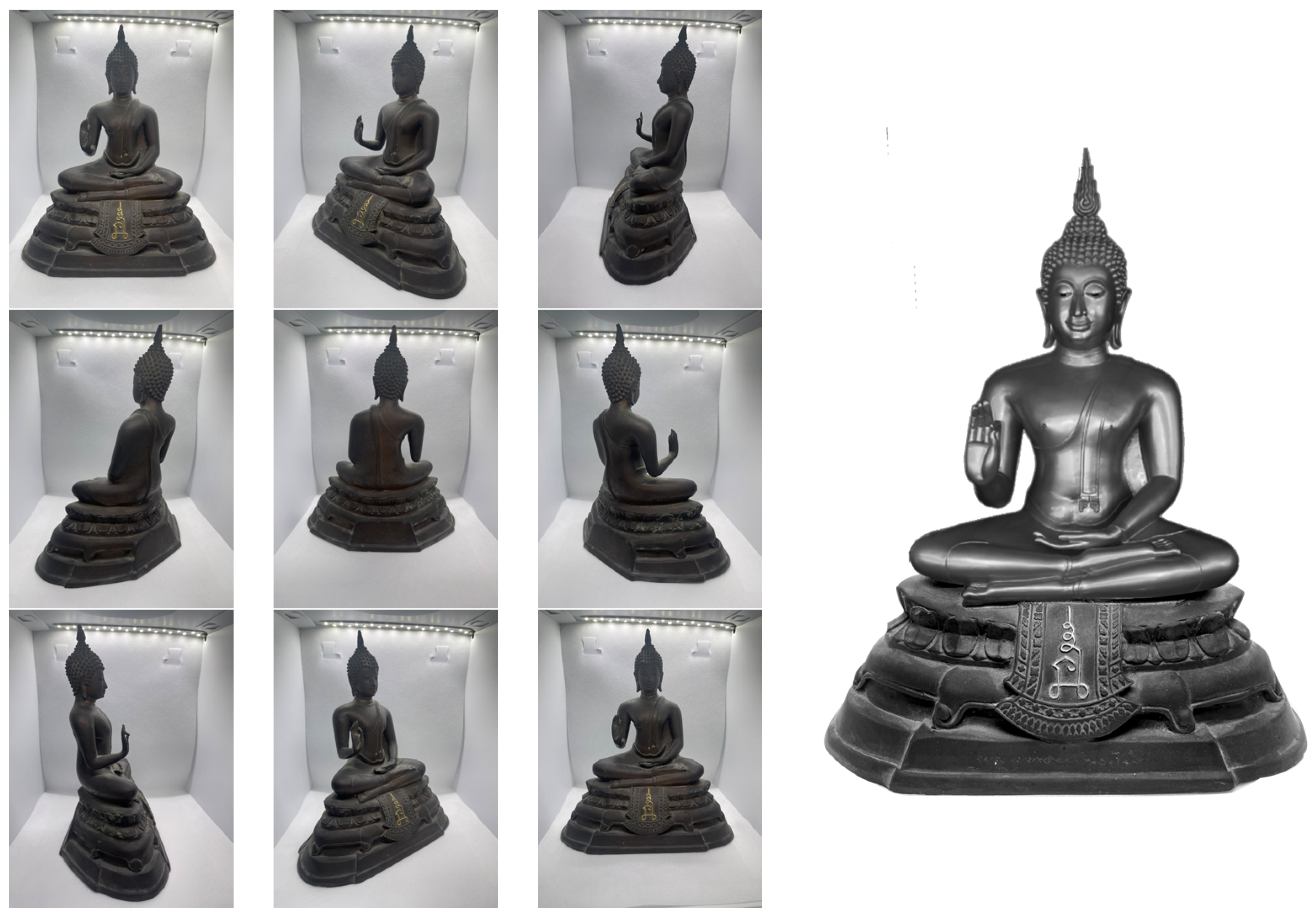
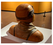
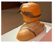
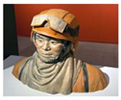
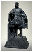
3D reconstruction using the photogrammetry method: Commercial software, e.g., AgiSoft, Reality Capture, and ReCap, uses the point cloud as the extracted feature to generate the 3D model. This software commonly requires the images taken to have an overlap, conveyed throughout the series of images to build the 3D model using the overlapping relation. Figure 1 shows the mesh model of the Buddha generated from the point cloud [32,33,34,35,36].
One major concern with 3D reconstruction from multiple 2D images is stereo pair image matching. The earlier stage of corresponding point cloud matching was introduced by Scale Invariant Feature Transform (SIFT) [37], Speeded Up Robust Features (SURF) [38], and Maximal Stable Extreme Region [39]. This technique demonstrates efficiency when each stereo pair image has an overlapping area of 70–80% consecutively throughout the image shots. Thus, each image shot should be taken within 15–20 degrees. Therefore, taking a picture of a cultural heritage object to generate a 3D model was not easy for the Thai artist. Figure 2a,b shows stereo pair image matching using the SIFT technique. It should be noted that input images were taken outside the overlapping range (≥80%), with the corresponding degree of each image being greater than 20 degrees. Therefore, sufficient stereo pair image matching cannot be generated to create a 3D model. Figure 2c shows the 3D reconstruction of multiple 2D images using the stereo pair image matching technique.
Moreover, to solve the problem of the stereo pair matching point cloud, a more sophisticated technique called Oriented FAST and Rotated BRIEF (ORB) has been introduced [40,41,42]. This technique is robust against geometric transformation when the camera is rotating around the object, and it also provides the capability of lens distortion correction and finding the object orientation in the image. However, this technique requires more computational time, and the user must consider whether they want to capture a huge object despite it taking more time to process. After solving the orientation and depth computation of images, a 3D model can be constructed using the point cloud and stereo-dense matching according to the results of computation. Figure 3 shows the results of 3D reconstruction using the dense matching of the point cloud.
In this study, traditional 3D preservation methods (Table 1) are compared with recent advancements in 3D reconstruction using 2D images. This paper proposes 3D reconstruction techniques for the digital preservation of cultural heritage objects based on depth estimation using SIFT. The contribution of this work consists of (1) image registration, which plays a fundamental role meticulously aligning multiple images with overlapping sections to establish spatial relationships; (2) depth computation, for determining the distance between objects and the camera, is crucial for accurate 3D modeling; (3) dense matching algorithms, which establish correspondences among points in different images following depth estimation, which, when combined with point cloud data, enables detailed 3D object reconstruction; and (4) the SIFT algorithm, which is essential in this process, for locating distinctive and invariant image features to facilitate image registration and depth calculation. The challenge of the proposed method among the recent works in the field of 3D reconstruction of tangible cultural heritage using 2D images (SfM and MVS) is the computational cost of depth estimation associated with SIFT-based 3D reconstruction.
SIFT-based depth estimation, while computationally efficient, requires certain limitations to be considered. Due to its focus on distinctive keypoints, SIFT can generate relatively sparse point clouds compared to dense techniques like MVS, potentially limiting the attainable resolution of the final 3D model. Moreover, SIFT feature matching can be sensitive to variations in lighting, viewpoint, and texture, sometimes introducing inaccuracies in depth estimation, especially for scenes with fewer distinct features. In objects possessing highly complex geometries, SIFT might struggle to reliably establish sufficient keypoints, hindering the capture of intricate details.
When compared to SfM and MVS, SIFT offers the advantage of lower computational cost due to its keypoint-centric approach. Conversely, SfM can incur higher computational demands, particularly during bundle adjustment, while MVS is often the most computationally intensive due to its dense reconstruction focus. In terms of implementation, SIFT benefits from well-established libraries, while SfM implementations might necessitate greater technical expertise, and MVS frequently depends on specialized software.
Ultimately, the choice between SIFT, SfM, and MVS hinges on a balance between several factors. SIFT provides a reasonable compromise between speed and accuracy for less demanding applications. SfM generally facilitates more robust camera pose estimation and scales well to larger image sets. MVS excels in generating highly detailed 3D models, albeit at the expense of greater computational requirements. Project-specific considerations such as the desired level of detail, computational resources, and the complexity of the target object or scene will guide the optimal 3D reconstruction technique.

2.2. Experimental Setup

This research aims to study tangible cultural heritage, e.g., sculptures in high relief and round relief. The contribution of this research can be divided into three major parts: (1) collecting and recording 2D images of tangible cultural heritage using a low-cost digital camera (DSLR); (2) constructing 3D models of the tangible cultural heritage using the input dataset; and (3) creating a collection of 3D models of tangible cultural heritage in digital format or in 3D printed format. The expected benefits of this work are two-fold: (1) the 3D archiving of tangible cultural heritage and (2) improving the accuracy of 3D models as reference data for the restoration of tangible cultural heritage in the future. Figure 4 illustrates the proposed method.
All images were taken from The National Art Museum of China, Beijing. The image dataset included sculptures, models, and artifacts. Input images were used to compute point clouds based on SIFT feature extraction [37]. The properties of SIFT include all possible coordinates and colors of the point cloud. The redundant and unnecessary point clouds were removed later. Therefore, the mesh model was generated, and the color map of the point cloud was constructed in this step. To construct the point cloud, monocular depth estimation was also used (monocular depth estimation is a computer vision technique used to predict the depth information of the scene) for depth map computation. Global-local path networks for monocular depth estimation [43] were used in the proposed method to generate monocular colors for the depth map. These colors were then used to define the depth property of the point cloud. In the final step, the Open3D library was used to generate the point cloud based on the color and depth information extracted from the input images. To construct the smooth surface of the mesh, the Poisson surface reconstruction algorithm [44] was also applied in the mesh generation process. Poisson distribution was applied to the point cloud construction. Figure 5 shows the global-local path networks for monocular depth estimation proposed by [43].
The block diagram of the proposed method also addresses the practical image capture challenges for optimal 3D reconstruction to ensure the successful reconstruction of tangible cultural heritage; careful image capture techniques are essential for stereo image matching. The incorporation of a calibration target into the scene was also considered to guarantee consistent camera viewpoints, facilitating automatic feature correspondence during image matching. Furthermore, a capture strategy was adopted, promoting an adequate image overlap. Some options were used, such as utilizing a fixed camera rig for consistent positioning or systematically capturing a sequence of overlapping images with the careful monitoring of camera locations.
Experiments were conducted using various camera angles to strike a balance between sufficient overlap and the capture of intricate details from diverse perspectives. Moreover, image capture software was employed for real-time overlap feedback to optimize the image capture process, preventing both deficient and excessive overlap.
Moreover, dealing with environmental conditions, particularly lighting, significantly impacted the success of the reconstruction process. Whenever possible, images in the museum were captured where controlled lighting could be maintained to reduce shadows and uneven illumination, ensuring consistent feature identification. If consistent lighting was unattainable, the capture of multiple image sets was considered under various lighting conditions. Therefore, the proposed approach requires configuration and a setting up process to ensure empowerment of the subsequent selection of the images yielding the most favorable reconstruction outcomes compared to SfM, MVS, and software-dependent methods like photogrammetry (AgiSoft, Reality Capture (Unreal), and ReCap).
The process began by carefully capturing multiple high-resolution photographs of the artifact from various angles. Ensuring significant overlap between images was crucial since this allowed the software to identify corresponding features across the photos. To enhance stability and minimize shadows that can disrupt depth estimation, a tripod was utilized, and consistent lighting was ensured throughout the capture process.
Next, specialized photogrammetry software (AgiSoft) was employed. This software meticulously analyzed the overlapping areas within the images, pinpointing common features such as corners and edges. Using these identified points, the software estimated the 3D position of the camera for each image. This data then fueled the creation of a dense 3D point cloud, accurately representing the surface of the artifact.
Finally, the depth map from this point cloud was derived. The software assigned X, Y, and Z coordinates (distance from the camera) to each point, subsequently translating them into a grayscale image where brightness corresponded to relative proximity to the camera.
The pseudo-code of the proposed method is shown below.

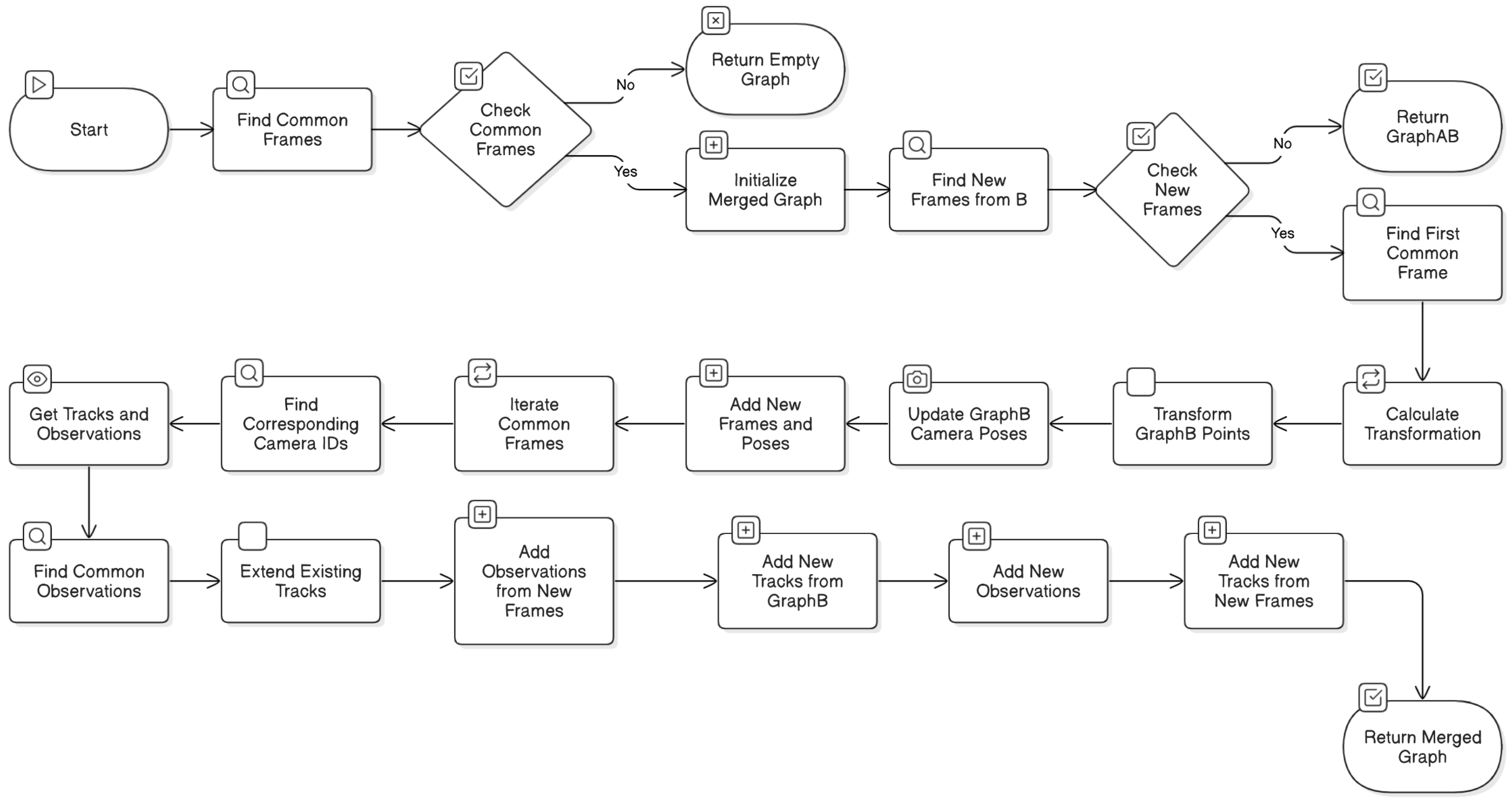
function merge2graphs(GraphA, GraphB):

  # Find common frames (images) between the two graphs commonFrames = intersect(GraphA.frames, GraphB.frames)

  # If no common frames, return empty graph
  if commonFrames is empty:
    return empty GraphAB

  # Initialize merged graph with GraphA
    GraphAB = GraphA

  # Find new frames from GraphB not present in GraphA
    newFramesFromB = setdiff(GraphB.frames, GraphA.frames)

  # If no new frames, return GraphAB as is
  if newFramesFromB is empty:
    return GraphAB

  # Find the first common frame
  firstCommonFrame = first element in commonFrames

  # Calculate transformation to align GraphB to GraphA's coordinate system
  RtBW2AW = concatenateRts(inverseRt(GraphA.Mot for firstCommonFrame), GraphB.Mot for firstCommonFrame)

  # Transform GraphB's 3D points using the calculated transformation
  GraphB.Str = transformPtsByRt(GraphB.Str, RtBW2AW)

  # Update GraphB's camera poses to reflect the new coordinate system
  for each frame in GraphB:
  GraphB.Mot for current frame = concatenateRts(GraphB.Mot for current frame, inverseRt(RtBW2AW))

  # Add new frames and camera poses from GraphB to GraphAB
  GraphAB.frames = combine GraphA.frames and newFramesFromB
  GraphAB.Mot = combine GraphA.Mot and GraphB.Mot for new frames

  # Iterate through common frames to merge and update tracks (3D points and observations)
  for each commonFrame in commonFrames:

  # Find corresponding camera IDs in both graphs
  cameraIDA = index of commonFrame in GraphA.frames
  cameraIDB = index of commonFrame in GraphB.frames

  # Get tracks (3D point indices) and observations for the common frame in both graphs
  trA, xyA = get tracks and observations from GraphA for cameraIDA
  trB, xyB = get tracks and observations from GraphB for cameraIDB

  # Find common observations (matching 2D points) between the two graphs
  xyCommon, iA, iB = intersect(xyA, xyB)

  # Extend existing tracks in GraphAB with observations from GraphB
  for each common observation:
  idA = track index in GraphA corresponding to current common observation
  idB = track index in GraphB corresponding to current common observation

  # Add observations from new frames in GraphB to the existing track in GraphAB
  for each new frame in GraphB:
   if observation exists for idB in current new frame:
    add observation to GraphAB for track idA and current new frame

    # Add new tracks from GraphB that are not present in GraphA
    xyNewFromB, iB = setdiff(xyB, xyA)

    for each new observation from GraphB:
     idB = track index in GraphB corresponding to current new observation

     # Add new track to GraphAB with observation from common frame
     add new track to GraphAB with observation from GraphB for idB and cameraIDA

     # Add observations from new frames in GraphB to the new track in GraphAB
     for each new frame in GraphB:
      if observation exists for idB in current new frame:
       add observation to GraphAB for new track and current new frame

   # Add new tracks that are only present in the new frames of GraphB
   # ... (This part of the code handles tracks that are not connected to the common frames)
return GraphAB
The pseudo-code is illustrated in the block diagram in Figure 6, together with an explanation of the method.
To handle fewer image overlaps and ensure per-image point clouds are aligned, we utilized the merge2graphs function in this task. This process ensures that the point clouds from both graphs are aligned in a standard coordinate system, effectively merging the 3D reconstructions from the two image pairs. The merge2graphs function is essential for aligning point clouds from two graphs, each representing a pair of images and their corresponding 3D points. This function enables the alignment of point clouds from images that do not directly overlap as long as they are connected through a chain of overlapping images. This approach reduces the need for excessive image overlaps, as the point cloud from an intermediate image can serve as a bridge to align the point clouds of non-overlapping images.
The alignment process in merge2graphs involves several key steps:
  • Identify Common Frames: The function identifies standard frames between the two graphs, which is crucial for establishing correspondences and aligning the coordinate systems.
  • Transform to Common Coordinate System: The function calculates the transformation that aligns the second graph’s coordinate system with the first graph’s coordinate system. This transformation is based on the camera poses of the first standard frame in both graphs. The 3D points of the second graph are then transformed using this transformation, and the camera poses are updated accordingly.
  • Merge Data: The frames, camera poses, and 3D points from both graphs are combined into a new graph. The observation indices are updated to ensure the 3D points are correctly associated with their corresponding image observations.
This process ensures that the point clouds from both graphs are aligned in a standard coordinate system, resulting in a merged 3D reconstruction from the two image pairs.
The ability to align point clouds from non-overlapping images reduces the number of required image overlaps, contributing to the efficiency of this approach.
The accuracy of depth information derived from the proposed method and other techniques (depth map, SfM, and MVS) was evaluated by comparing their deviation from ground truth references, such as CT scans, laser scans, manual measurements, and rendered synthetic models. The accuracy metric, the Percentage of Correct Points (PCP), represents the proportion of points with positional errors below a predefined threshold (1 mm). The proposed method demonstrated superior accuracy compared to the baseline (depth map), particularly in Dataset 2, where it achieved 79% accuracy, indicating a 21% reduction in deviation from ground truth. In Dataset 3, suboptimal lighting conditions or low-texture surfaces likely reduced feature-matching reliability, resulting in lower accuracy (67.3%). Factors influencing accuracy include scene contrast, lighting consistency, and image overlap. It is important to note that the accuracy metric reflects relative performance under controlled experimental conditions and that ground truth acquisition may introduce minor inherent errors. Overall, the accuracy percentages highlight the proposed method’s effectiveness in generating geometrically consistent 3D reconstructions, particularly in high-contrast scenarios, validating its potential for cultural heritage preservation.

3. Results and Discussion

The proposed method in this study was tested using three image datasets, and the reconstruction results were compared with the original depth map. All images were captured using a DSLR camera from different angles. Following photogrammetry and stereo photography techniques, the camera was rotated 15–20 degrees for each shot. Three images were used in the experiments, each divided into 21, 9, and 18 sub-images, respectively. All images were JPEG-compressed and had a uniform resolution of 12 megapixels. The test results, including depth information accuracy, running time, and number of generated point clouds, are summarized in Table 2. The comparison of reconstruction results between the proposed method and the original depth map is shown in Table 3.
The experiment demonstrates that the proposed method provided depth information accuracy exceeding 65% across all tested image datasets. In Dataset 1, the proposed method achieved 70.7% accuracy, closely approaching the SfM method’s 72.2%. Both significantly outperformed the depth map and MVS methods. The Dataset 2 results further confirmed the superiority of the proposed method, which achieved 79% accuracy, surpassing all other methods. The depth map method performed the worst (20.4% accuracy), while SfM (71.7%) and MVS (69.9%) trailed behind the proposed method. For Dataset 3, the results were closer, with the proposed method achieving 67.3% accuracy, compared to 65.5% (SfM) and 66.2% (MVS). Again, the proposed method demonstrated the highest accuracy, while the depth map method remained the least accurate at 25.5%.
The depth map method also demonstrated a clear advantage in terms of running time. It consistently completed in under 1 s across all three image datasets. In contrast, the proposed method required 120 s for Dataset 1 (21 images), 72 s for Dataset 2 (9 images), and 96 s for Dataset 3 (18 images). Both the SfM and MVS methods exhibited even longer running times than the proposed method across all datasets: SfM required 156, 98, and 128 s, while MVS took 220, 160, and 184 s, respectively.
This experiment demonstrates that, even with consistent image size and JPG format, different methods yield varying results for depth information accuracy and running time. While the number of images used influences running time, it does not appear to significantly impact the accuracy of depth information.
Importantly, the proposed method stands out by achieving the highest depth information accuracy (79%) for Image Dataset 2. This may be related to the distinct color contrast between objects and backgrounds within those images, a characteristic less prominent in the other datasets.
The proposed method demonstrated superiority in generating point clouds. It consistently yielded the highest count across all three image datasets (978,490, 2,588,931, and 2,759,780 positions, respectively). The depth map method was consistently placed second (725,830, 814,300, and 943,360 positions). Importantly, the results indicate that image size does not significantly influence the number of point clouds generated.
Recent works based on depth maps [44,45], SfM [46,47], and MVS [48,49] were also investigated. In [44], a novel approach to real-time dense visual SLAM (Simultaneous Localization and Mapping) was presented. This system is capable of capturing comprehensive, dense, and globally consistent surfel-based maps of room-scale environments. It operates incrementally in an online fashion using an RGB-D camera without relying on pose graph optimization or any post-processing steps. This was accomplished using dense frame-to-model camera tracking and windowed surfel-based fusion coupled with frequent model refinement through non-rigid surface deformation. The approach involved the application of local model-to-model surface loop closure optimization as often as possible to stay close to the mode of the map distribution while utilizing global loop closure to recover from arbitrary drift and maintain global consistency. In [45], a robust approach was proposed for reconstructing indoor scenes from RGB-D videos. The approach combined the geometric registration of scene fragments with robust global optimization-based online processes. The key idea involved addressing the issue of geometric registration errors caused by sensor noise and aliasing of geometric detail. The optimization approach was found to disable erroneous geometric alignments, even when they outnumbered correct ones, by utilizing a global optimization framework based on online processes to identify discontinuities and enable robust estimation, leading to improved accuracy in the reconstructed scene models.
In [46], a simple and effective single-shot 3D reconstruction approach was presented using a grid pattern-based structured-light vision method. The system consisted of a camera and a low-cost LED projector. The grid pattern-based structured-light model was combined with the camera pinhole model and multiple light plane constraints. The tangential distortion and radial distortion were compensated for. By not using the epipolar constraint, the error propagation caused by the low calibration accuracy of the stereo vision model was avoided. The grid pattern consisted of a number of intersecting light stripes. The common algorithms for stripe center extraction were inaccurate. However, the intersections of the grid lines could be precisely extracted. Following the topological distribution of the intersections, an effective extraction method was investigated to gather the sub-pixel centers on the grid strips. The white circles on the calibration board could disturb the extraction. To solve the problem, the gray value of the ellipse region on the input image was properly and automatically attenuated. A calibration method based on the coplanar constraint was presented, which could be implemented in one step. In [47], an efficient covisibility-based incremental SfM method was proposed to improve reconstruction efficiency for both unordered and sequential images. The method exploited covisibility and registration dependency to describe image connections, enabling a unified framework for reconstructing various image types. This approach was shown to be three times faster than state-of-the-art methods on feature matching with a faster order of magnitude on reconstruction, without sacrificing accuracy.
In [48], a new method was introduced to efficiently plan viewpoints and trajectories for 3D reconstruction using a quadcopter with an RGB camera in outdoor environments. The method maximized information gain while minimizing travel distance, respecting the limited flight time of quadcopters. It used a hierarchical volumetric representation to distinguish between unknown, free, and occupied space, and handled occlusions efficiently. The method also utilized free-space information to avoid obstacles and plan collision-free flight paths. The authors demonstrated the effectiveness of their method through compelling 3D reconstructions and a thorough quantitative evaluation.
In [49], a novel approach was proposed to enhance surface reconstruction in urban environments by integrating aerial and ground images. The key innovation was based on leveraging photogrammetric mesh models for aerial-ground image matching, overcoming the challenges posed by significant viewpoint and illumination differences. This method, with linear time complexity, was shown to effectively handle low overlap scenarios using multi-view images and could seamlessly integrate with existing SfM and MVS pipelines. The process involved the separate reconstruction of aerial and ground images, co-registration using weak georeferencing data, rendering of aerial models to ground views, and feature matching with outlier removal. Finally, oriented 3D patches facilitated correspondence propagation to aerial views. The experimental results demonstrated superior performance, achieving successful matching in all ten challenging pairs compared to only three for the second-best method, while also enabling a more complete and stable reconstruction.
The results of this study were compared with previous works based on depth maps, SfM, and MVS. This current research focuses on enhancing the accuracy of 3D reconstruction for cultural heritage preservation by refining depth estimation using SIFT features. This emphasis on improving depth estimation through feature matching distinguishes the present work from others. Depth map methods focus on a dense SLAM system for real-time reconstruction without a pose graph, using frame-to-model tracking, non-rigid surface deformation [44], and the robust reconstruction of indoor scenes from RGB-D videos using geometric registration and global optimization [45]. SfM methods [46,47] propose single-shot 3D reconstruction using a grid pattern-based structured-light vision system, together with an efficient covisibility-based incremental SfM method for both unordered and sequential images. MVS methods [48,49] involve viewpoint and trajectory optimization for aerial multi-view stereo 3D reconstruction, together with leveraging photogrammetric mesh models for aerial-ground feature point matching toward integrated 3D reconstruction.
In contrast to these previous works, the proposed approach specifically targets cultural heritage preservation and utilizes a low-cost image acquisition setup, potentially making it more accessible for broader applications. However, its reliance on SIFT features may limit its robustness in certain scenarios, such as those involving repetitive patterns or low-texture regions. In such cases, incorporating complementary techniques from the cited works, such as dense frame-to-model tracking or leveraging photogrammetric mesh models, could enhance the robustness of the proposed approach.

4. Conclusions

According to the reconstruction results in Section 3, the proposed method can generate more meaningful point clouds compared to the original depth map. For example, in Image Dataset 2, the proposed method generated 2,588,931 point clouds, whereas the original depth map method generated only 814,300. In Image Dataset 3, the proposed method generated 2,759,780 point clouds, whereas the original depth map method generated only 943,360. In terms of depth information accuracy, an accuracy of 72.33% was achieved, whereas the original depth map method achieved only 24.93%. One major disadvantage of the proposed method is the running time, since monocular depth estimation and Poisson distribution techniques are required to generate the mesh. The experiment involving photographs being taken of a tangible cultural heritage object highlighted the importance of lighting conditions. As described earlier, all images in this work were taken at The National Art Museum of China, Beijing; therefore, it was not possible to control the lighting and other environmental factors to create the most suitable surroundings for our reconstruction method.
The experimental results highlight key takeaways. Compared to the depth map method, the proposed method offers significantly improved accuracy in depth information and point cloud generation, though at the cost of longer running time. Additionally, the proposed method appears particularly effective for image datasets featuring high color contrast between objects and backgrounds. It is important to note that this conclusion is currently based on visual observation; further analysis of specific color features (hue, saturation, etc.) is required. Future work should explore the method’s performance with diverse image datasets (varying sizes and types) and prioritize algorithm speed optimization.

Author Contributions

Conceptualization, P.V. and X.L.; methodology, P.V.; software, F.P.; validation, P.V., C.C. and F.P.; formal analysis, P.V. and X.L.; investigation, X.L.; resources, P.V.; data curation, P.V.; writing—original draft preparation, P.V. and F.P.; writing—review and editing, P.V.; visualization, F.P.; supervision, P.V. and X.L.; project administration, P.V.; funding acquisition, P.V. All authors have read and agreed to the published version of the manuscript.

Funding

This research was funded by the National Science, Research, and Innovation Fund (NSRF) and King Mongkut’s University of Technology North Bangkok under Contract no. KMUTNB-FF-66-18.

Data Availability Statement

The image dataset and code used in this study are available from the corresponding author upon reasonable request.

Acknowledgments

This research partially utilized computational resources provided by the China Scholarship Council (CSC) for the Senior Visiting Scholarship Program of the School of Computer Science and Technology, Beijing Institute Technology (BIT).

Conflicts of Interest

The authors declare no conflicts of interest.

References

  1. Nilsson, T.; Thorell, K. Cultural Heritage Preservation: The Past, the Present and the Future; Halmstad University Press: Halmstad, Sweden, 2018. [Google Scholar]
  2. De la Torre, M. Values and Heritage Conservation. Herit. Soc. 2013, 6, 155–166. [Google Scholar] [CrossRef]
  3. De la Torre, M. Values in Heritage Conservation: A Project of The Getty Conservation Institute. J. Preserv. Technol. 2014, 45, 19–24. [Google Scholar]
  4. Kosel, J.; Ropret, P. Overview of Fungal Isolates on Heritage Collections of Photographic Materials and Their Biological Potency. J. Cult. Herit. 2021, 48, 277–291. [Google Scholar] [CrossRef]
  5. Hiebel, G.; Aspöck, E.; Kopetzky, K. Ontological Modeling for Excavation Documentation and Virtual Reconstruction of an Ancient Egyptian Site. J. Comput. Cult. Herit. 2021, 14, 1–14. [Google Scholar] [CrossRef]
  6. Grbić, M.L.; Dimkić, I.; Janakiev, T.; Kosel, J.; Tavzes, Č.; Popović, S.; Knežević, A.; Legan, L.; Retko, K.; Ropret, P.; et al. Uncovering the Role of Autochthonous Deteriogenic Biofilm Community: Rožanec Mithraeum Monument (Slovenia). Microb. Ecol. 2024, 87, 87. [Google Scholar] [CrossRef] [PubMed]
  7. Stanco, F.; Battiato, S.; Gallo, G. Digital Imaging for Cultural Heritage Preservation. Analysis, Restoration, and Reconstruction of Ancient Artworks; CRC Press: Boca Raton, FL, USA, 2011. [Google Scholar]
  8. Neumüller, M.; Reichinger, A.; Rist, F.; Kern, C. 3D Printing for Cultural Heritage: Preservation, Accessibility, Research and Education. In 3D Research Challenges in Cultural Heritage: A Roadmap in Digital Heritage Preservation; Ioannides, M., Quak, E., Eds.; Springer: Berlin/Heidelberg, Germany, 2014; pp. 119–134. [Google Scholar]
  9. Tucci, G.; Bonora, V.; Conti, A.; Fiorini, L. High-Quality 3D Models and Their Use in a Cultural Heritage Conservation Project. Int. Arch. Photogramm. Remote Sens. Spat. Inf. Sci. 2017, 42, 687–693. [Google Scholar] [CrossRef]
  10. Kolay, S. Cultural Heritage Preservation of Traditional Indian Art Through Virtual New-Media. Procedia Soc. Behav. Sci. 2016, 225, 309–320. [Google Scholar] [CrossRef]
  11. Trček, D. Cultural Heritage Preservation by Using Blockchain Technologies. Herit. Sci. 2022, 10, 6. [Google Scholar] [CrossRef]
  12. Selmanović, E.; Rizvic, S.; Harvey, C.; Boskovic, D.; Hulusic, V.; Chahin, M.; Sljivo, S. Improving Accessibility to Intangible Cultural Heritage Preservation Using Virtual Reality. J. Comput. Cult. Herit. 2020, 13, 1–19. [Google Scholar] [CrossRef]
  13. Alivizatou-Barakou, M.; Kitsikidis, A.; Tsalakanidou, F.; Dimitropoulos, K.; Giannis, C.; Nikolopoulos, S.; Al Kork, S.; Denby, B.; Buchman, L.; Adda-Decker, M.; et al. Intangible Cultural Heritage and New Technologies: Challenges and Opportunities for Cultural Preservation and Development. In Mixed Reality and Gamification for Cultural Heritage; Ioannides, M., Magnenat-Thalmann, N., Papagiannakis, G., Eds.; Springer: Cham, Switzerland, 2017; pp. 129–158. [Google Scholar]
  14. Gomes, L.; Bellon, O.R.P.; Silva, L. 3D Reconstruction Methods for Digital Preservation of Cultural Heritage: A Survey. Pattern Recognit. Lett. 2014, 50, 3–14. [Google Scholar] [CrossRef]
  15. Tychola, K.; Tsimperidis, I.; Papakostas, G. On 3D Reconstruction Using RGB-D Cameras. Digital 2022, 2, 401–421. [Google Scholar] [CrossRef]
  16. Doulamis, A.; Voulodimos, A.; Protopapadakis, E.; Doulamis, N.; Makantasis, K. Automatic 3D Modeling and Reconstruction of Cultural Heritage Sites from Twitter Images. Sustainability 2020, 12, 4223. [Google Scholar] [CrossRef]
  17. Webb, E.K.; Robson, S.; Evans, R. Quantifying Depth of Field and Sharpness for Image-Based 3D Reconstruction of Heritage Objects. ISPRS Int. Arch. Photogramm. Remote Sens. Spat. Inf. Sci. 2020, 439, 911–918. [Google Scholar] [CrossRef]
  18. Jung, S.; Lee, Y.S.; Lee, Y.; Lee, K.J. 3D Reconstruction Using 3D Registration-Based ToF-Stereo Fusion. Sensors 2022, 22, 8369. [Google Scholar] [PubMed]
  19. Liang, Y.; Yang, Y.; Fan, X.; Cui, T. Efficient and Accurate Hierarchical SfM Based on Adaptive Track Selection for Large-Scale Oblique Images. Remote Sens. 2023, 15, 1374. [Google Scholar] [CrossRef]
  20. Ye, Z.; Bao, C.; Zhou, X.; Liu, H.; Bao, H.; Zhang, G. EC-SfM: Efficient Covisibility-Based Structure-from-Motion for Both Sequential and Unordered Images. IEEE Trans. Circuits Syst. Video Technol. 2023, 34, 110–123. [Google Scholar] [CrossRef]
  21. Chen, Y.; Yu, Z.; Song, S.; Yu, T.; Li, J.; Lee, G.H. AdaSfM: From Coarse Global to Fine Incremental Adaptive Structure from Motion. In Proceedings of the 2023 IEEE International Conference on Robotics and Automation (ICRA), London, UK, 29 May–1 June 2023; pp. 1–11. [Google Scholar]
  22. Kar, A.; Häne, C.; Malik, J. Learning a Multi-View Stereo Machine. In Proceedings of the NIPS’17: Proceedings of the 31st International Conference on Neural Information Processing Systems, Long Beach, CA, USA, 4–9 December 2017; Curran Associates Inc.: New York, NY, USA, 2017; pp. 364–375. [Google Scholar]
  23. Papaioannou, G.; Schreck, T.; Andreadis, A.; Mavridis, P.; Gregor, R.; Sipiran, I.; Vardis, K. From Reassembly to Object Completion: A Complete Systems Pipeline. J. Comput. Cult. Herit. 2017, 10, 1–22. [Google Scholar]
  24. Gomes, L.; Silva, L.; Bellon, O.R.P. Exploring RGB-D Cameras for 3D Reconstruction of Cultural Heritage: A New Approach Applied to Brazilian Baroque Sculptures. J. Comput. Cult. Herit. 2018, 11, 1–24. [Google Scholar]
  25. Utomo, P.; Wibowo, C.P. 3D Reconstruction of Temples in the Special Region of Yogyakarta by Using Close-Range Photogrammetry. Proc. Semin. Nas. Teknol. Inf. Multimedia. 2017, 5, 1–15. [Google Scholar]
  26. Cripps, P.; Greenhalgh, A.; Fellows, D.; May, K.; Robinson, D. Ontological Modelling of the Work of the Centre for Archaeology; CIDOC CRM Technical Paper; Univerzita Karlova: Prague, Czech Republic, 2004; pp. 1–33. [Google Scholar]
  27. Shekhovtsov, A.; Reinbacher, C.; Graber, G.; Pock, T. Solving Dense Image Matching in Real-Time Using Discrete-Continuous Optimization. In Proceedings of the CVWW’16: Proceedings of the 21st Computer Vision Winter Workshop, Rimske Toplice, Slovenia, 3–5 February 2016; Slovenian Pattern Recognition Society: Rimske Toplice, Slovenia, 2016; pp. 1–13. [Google Scholar]
  28. Geiger, A.; Ziegler, J.; Stiller, C. Stereoscan: Dense 3D Reconstruction in Real-Time. In Proceedings of the 2011 IEEE Intelligent Vehicles Symposium (IV), Baden-Baden, Germany, 5–9 June 2011; pp. 963–968. [Google Scholar]
  29. Hinzmann, T.; Schönberger, J.; Pollefeys, M.; Siegwart, R. Mapping on the Fly: Real-Time 3D Dense Reconstruction, Digital Surface Map and Incremental Orthomosaic Generation for Unmanned Aerial Vehicles. In Proceedings of the Field and Service Robotics—Results of the 11th International Conference, Zurich, Switzerland, 12–15 September 2018; Springer: Zurich, Switzerland, 2018; pp. 383–396. [Google Scholar]
  30. Vokhmintcev, A.; Timchenko, M. The New Combined Method of the Generation of a 3D Dense Map of Environment Based on History of Camera Positions and the Robot’s Movements. Acta Polytech. Hung. 2020, 17, 95–108. [Google Scholar]
  31. Zhao, C.; Li, S.; Purkait, P.; Duckett, T.; Stolkin, R. Learning Monocular Visual Odometry with Dense 3D Mapping from Dense 3D Flow. In Proceedings of the 2018 IEEE/RSJ International Conference on Intelligent Robots and Systems (IROS), Madrid, Spain, 1–5 October 2018; pp. 6864–6871. [Google Scholar]
  32. Visutsak, P. Stereo-Photogrammetry Technique for 3D Reconstruction; Technical Report; KMUTNB: Bangkok, Thailand, 2023. (In Thai) [Google Scholar]
  33. Do, P.N.B.; Nguyen, Q.C. A Review of Stereo-Photogrammetry Method for 3-D Reconstruction in Computer Vision. In Proceedings of the 19th International Symposium on Communications and Information Technologies (ISCIT), Ho Chi Minh City, Vietnam, 25–27 September 2019; pp. 138–143. [Google Scholar]
  34. Eulitz, M.; Reiss, G. 3D Reconstruction of SEM Images by Use of Optical Photogrammetry Software. J. Struct. Biol. 2015, 191, 190–196. [Google Scholar] [PubMed]
  35. Karami, A.; Menna, F.; Remondino, F. Combining Photogrammetry and Photometric Stereo to Achieve Precise and Complete 3D Reconstruction. Sensors 2022, 22, 8172. [Google Scholar] [CrossRef]
  36. Torresani, A.; Remondino, F. Videogrammetry vs. Photogrammetry for Heritage 3D Reconstruction. Int. Arch. Photogramm. Remote Sens. Spat. Inf. Sci. 2019, XLII-2/W15, 1157–1162. [Google Scholar]
  37. Lowe, D.G. Distinctive Image Features from Scale-Invariant Keypoints. Int. J. Comput. Vis. 2004, 60, 91–110. [Google Scholar]
  38. Bay, H.; Ess, A.; Tuytelaars, T.; Gool, L.V. Speeded-Up Robust Features (SURF). Comput. Vis. Image Underst. 2008, 110, 346–359. [Google Scholar]
  39. Matas, J.; Chum, O.; Urban, M.; Pajdla, T. Robust Wide Baseline Stereo from Maximally Stable Extremal Regions. Image Vis. Comput. 2004, 22, 761–767. [Google Scholar]
  40. Bansal, M.; Kumar, M. 2D Object Recognition: A Comparative Analysis of SIFT, SURF and ORB Feature Descriptors. Multimedia. Tools Appl. 2021, 80, 18839–18857. [Google Scholar]
  41. Panchal, P.; Panchal, S.R.; Shah, S. A Comparison of SIFT and SURF. Int. J. Innov. Res. Comput. Commun. Eng. 2013, 1, 323–327. [Google Scholar]
  42. Setiawan, R.; Yunmar, A.; Tantriawan, H. Comparison of Speeded-Up Robust Feature (SURF) and Oriented FAST and Rotated BRIEF (ORB) Methods in Identifying Museum Objects Using Low Light Intensity Images. In Proceedings of the International Conference on Science, Infrastructure Technology and Regional Development, South Lampung, Indonesia, 25–26 October 2019; IOP Publishing: South Lampung, Indonesia, 2020; pp. 1–9. [Google Scholar]
  43. Kim, D.; Ga, W.; Ahn, P.; Joo, D.; Chun, S.; Kim, J. Global-Local Path Networks for Monocular Depth Estimation with Vertical CutDept. arXiv 2022, arXiv:2201.07436. [Google Scholar]
  44. Kazhdan, M.; Bolitho, M.; abd Hoppe, H. Poisson Surface Reconstruction. In Proceedings of the Fourth Eurographics Symposium on Geometry Processing, Cagliari, Italy, 26–28 June 2006; Eurographics Association: Goslar, Germany, 2006; pp. 61–70. [Google Scholar]
  45. Whelan, T.; Leutenegger, S.; Salas-Moreno, R.F.; Glocker, B.; Davison, A.J. ElasticFusion: Dense SLAM without a pose graph. Robot. Sci. Syst. 2015, 11, 3. [Google Scholar]
  46. Choi, S.; Zhou, Q.-Y.; Koltun, V. Robust reconstruction of indoor scenes. In Proceedings of the IEEE Conference on Computer Vision and Pattern Recognition, Boston, MA, USA, 7–12 June 2015. [Google Scholar]
  47. Liu, B.; Yang, F.; Huang, Y.; Zhang, Y.; Wu, G. Single-shot 3D reconstruction using grid pattern-based structured-light vision method. Appl. Sci. 2022, 12, 10602. [Google Scholar]
  48. Hepp, B.; Nießner, M.; Hilliges, O. Plan3d: Viewpoint and trajectory optimization for aerial multi-view stereo reconstruction. ACM Trans. Graph. TOG 2018, 38, 1–17. [Google Scholar] [CrossRef]
  49. Zhu, Q.; Wang, Z.; Hu, H.; Xie, L.; Ge, X.; Zhang, Y. Leveraging photogrammetric mesh models for aerial-ground feature point matching toward integrated 3D reconstruction. ISPRS J. Photogramm. Remote Sens. 2020, 166, 26–40. [Google Scholar] [CrossRef]
Figure 1. 3D mesh model generated by the photogrammetry method.
Asi 08 00043 g001
Figure 2. Stereo pair image matching using SIFT [37].
Asi 08 00043 g002
Figure 3. 3D Model with Texture [37].
Asi 08 00043 g003
Figure 4. Block diagram of the proposed method.
Asi 08 00043 g004
Figure 5. Global-local path networks for monocular depth estimation [43].
Asi 08 00043 g005
Figure 6. Illustration of the pseudo-code.
Asi 08 00043 g006
Table 1. Recent techniques used in the preservation of 3D cultural heritage.
Preservation TechniquesAdvantageDisadvantage
1. Measuring by hand1. Cost-effective: The primary advantage is the low cost.
2. Tradition: This method holds historical value.
1. Damage risk: Direct contact can damage delicate artifacts.
2. Error-prone: Human error leads to inaccurate measurements.
3. Time-consuming: Measuring intricate artifacts by hand is a slow process.
4. Difficult to replicate: Inconsistency of the technique hinders replication.
5. Limited data: Hand measurements miss subtle details.
2. Kinect camera1. Depth of information: Kinect captures depth data for accurate 3D models.
2. Non-contact method: Kinect is non-invasive, reducing damage risk.
3. Relatively low cost: Kinect is affordable compared to high-end scanners.
1. Limited field of view: Kinect’s narrow field of view might require multiple capture and stitching.
2. Operational range: Kinect’s limited range might not be suitable for large artifacts or specific distance requirements.
3. Resolution limitations: Kinect might not capture intricate details.
4. Accuracy for complex shapes: Kinect may struggle with capturing highly intricate shapes or deep cavities.
3. 3D laser scanner1. Unmatched precision: 3D laser scanners offer the highest level of accuracy for digital preservation.
2. Speed and efficiency: Laser scanners capture data quickly, streamlining the process.
3. Richness of data: 3D laser scanners capture geometry and color for visually rich models.
1. High cost: 3D laser scanners are the most expensive option.
2. Accessibility and setup: Setting up and using laser scanners requires specialized training.
3. Data storage: High-density scans require significant storage capacity.
4. Photogrammetry1. Accessibility: Photogrammetry is accessible with a camera and software.
2. Portability: Photogrammetry is highly portable due to the use of a camera.
3. Color and texture preservation: Photogrammetry captures realistic textures and colors.
1. Overlapping images: Accurate photogrammetry requires carefully planned, overlapping images.
2. Processing power: Photogrammetry can be computationally demanding.
3. Limitations with certain surfaces: Photogrammetry struggles with reflective, transparent, or featureless surfaces.
Table 2. Experimental results.
Accuracy of Depth InformationRunning TimeNumber of Point Clouds
MethodImage Dataset 1Image Dataset 2Image Dataset 3Image Dataset 1Image Dataset 2Image Dataset 3Image Dataset 1Image Dataset 2Image Dataset 3
Proposed method70.7%79.0%67.3%1207296978,4902,588,9312,759,780
Depth map (Photogrammetry)28.9%20.4%25.5%0.8050.3450.69725,830814,300943,360
SfM [19]72.2%71.1%65.5%15698128684,210985,600724,350
MVS [22]68.4%69.9%66.2%220160184583,420876,540637,400
Table 3. Reconstruction results.
Image Dataset #1
Input
Image
Proposed
Method
Depth
Map
SfM [19]MVS [22]
Asi 08 00043 i001Asi 08 00043 i002Asi 08 00043 i003Asi 08 00043 i004Asi 08 00043 i005
Asi 08 00043 i006Asi 08 00043 i007Asi 08 00043 i008Asi 08 00043 i009Asi 08 00043 i010
Asi 08 00043 i011Asi 08 00043 i012Asi 08 00043 i013Asi 08 00043 i014Asi 08 00043 i015
Image Dataset #2
Input
Image
Proposed
Method
Depth
Map
SfM [19]MVS [22]
Asi 08 00043 i016Asi 08 00043 i017Asi 08 00043 i018Asi 08 00043 i019Asi 08 00043 i020
Asi 08 00043 i021Asi 08 00043 i022Asi 08 00043 i023Asi 08 00043 i024Asi 08 00043 i025
Asi 08 00043 i026Asi 08 00043 i027Asi 08 00043 i028Asi 08 00043 i029Asi 08 00043 i030
Image Dataset #3
Input
Image
Proposed
Method
Depth
Map
SfM [19]MVS [22]
Asi 08 00043 i031Asi 08 00043 i032Asi 08 00043 i033Asi 08 00043 i034Asi 08 00043 i035
Asi 08 00043 i036Asi 08 00043 i037Asi 08 00043 i038Asi 08 00043 i039Asi 08 00043 i040
Asi 08 00043 i041Asi 08 00043 i042Asi 08 00043 i043Asi 08 00043 i044Asi 08 00043 i045
Disclaimer/Publisher’s Note: The statements, opinions and data contained in all publications are solely those of the individual author(s) and contributor(s) and not of MDPI and/or the editor(s). MDPI and/or the editor(s) disclaim responsibility for any injury to people or property resulting from any ideas, methods, instructions or products referred to in the content.

