A Novel Combination of Distributed Ledger Technologies on Internet of Things: Use Case on Precision Agriculture


Abstract
:1. Introduction
1.1. IOTA Constituents
1.2. IOTA Functionality
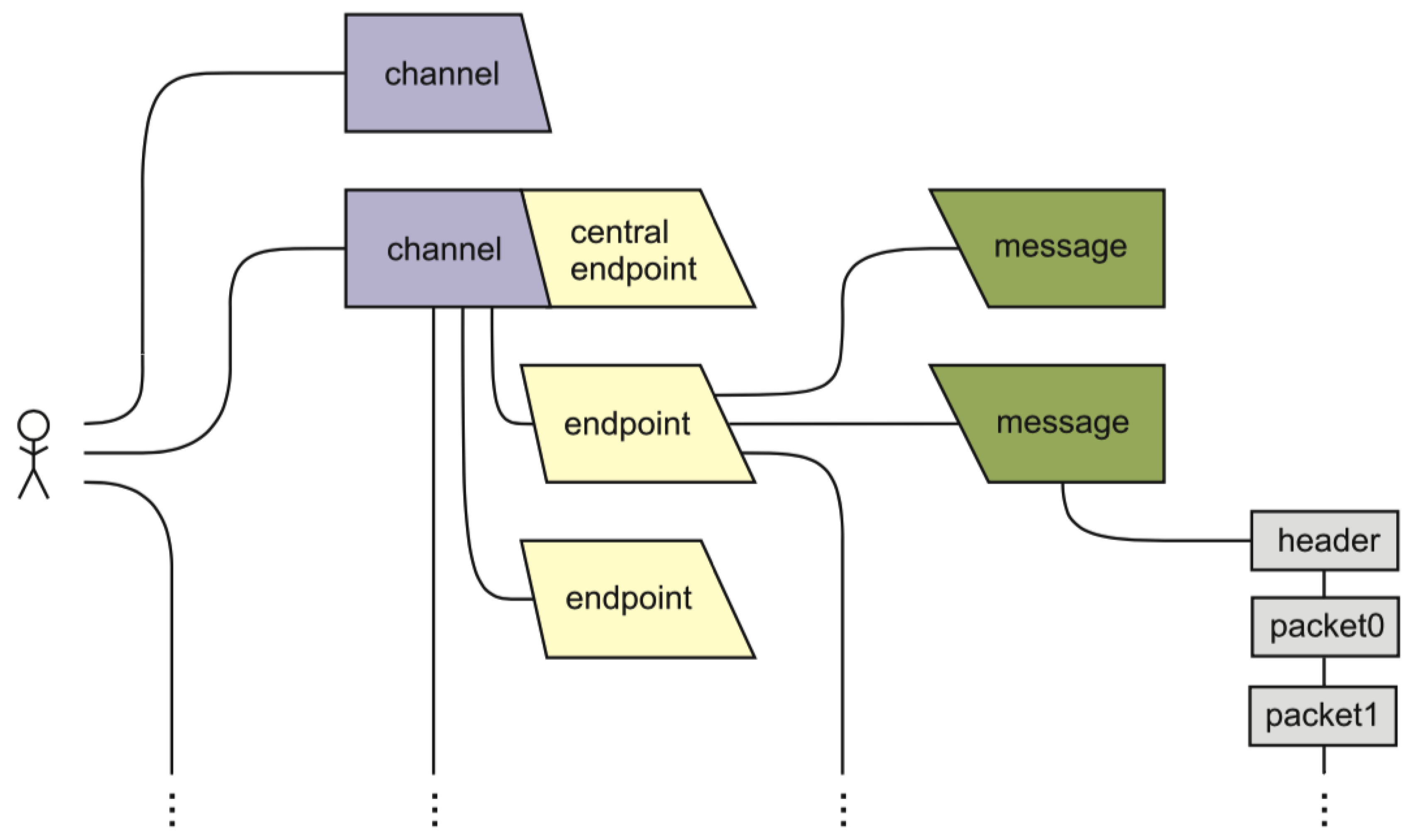
1.3. MAM Specification
1.4. MAM Protocol
1.5. MAM in IOTA
1.6. IOTA Challenges
2. Related Work
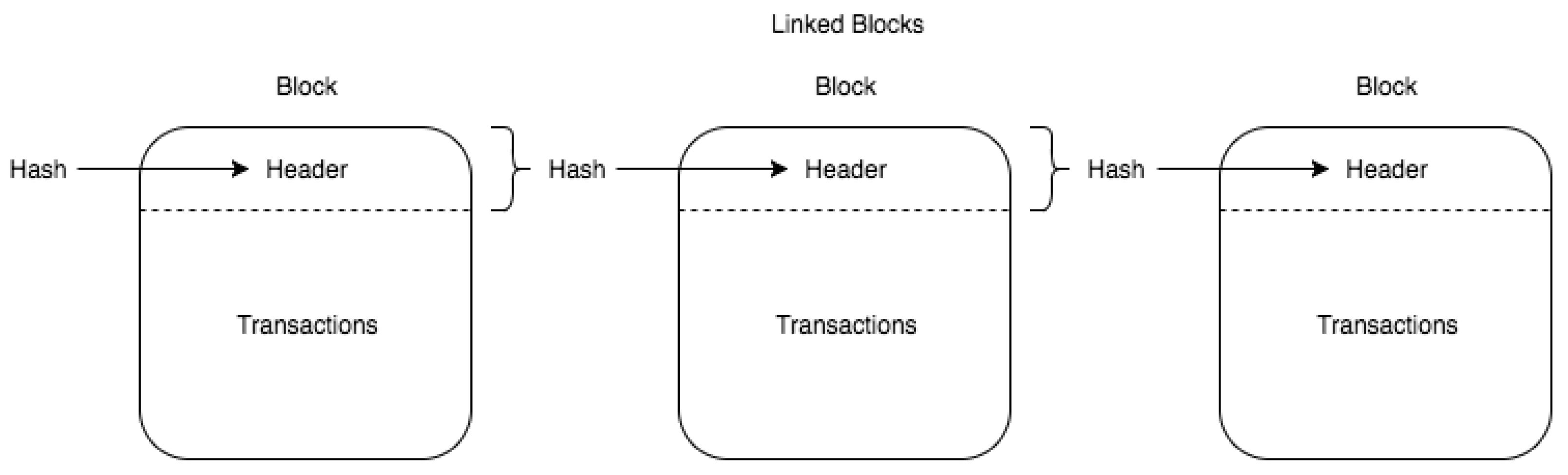
2.1. Blockchain
2.2. IoT End and Super Nodes
2.3. IoT Security and Privacy Challenges
2.4. Blockchain @ IoT
3. System Architecture and Implementation
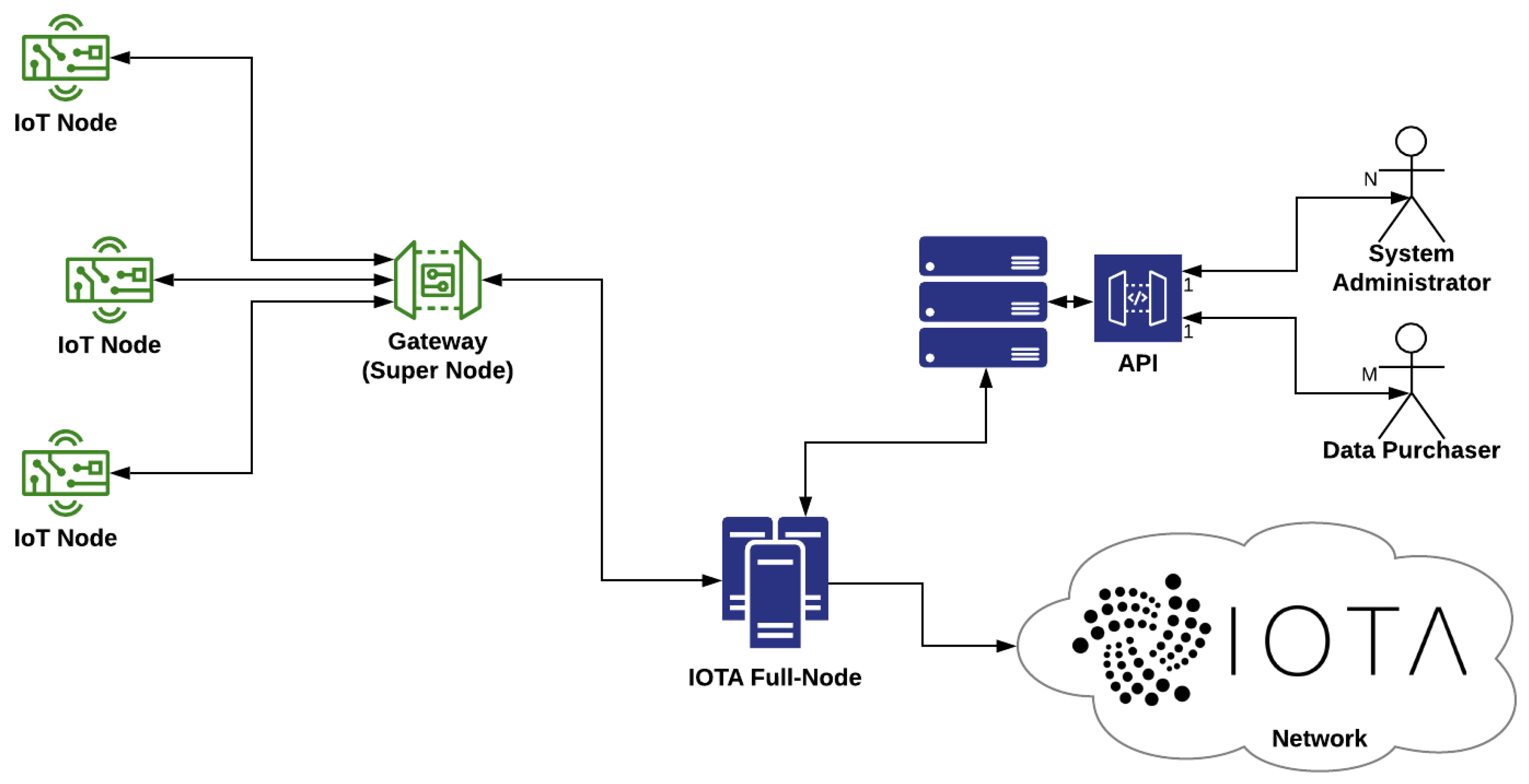
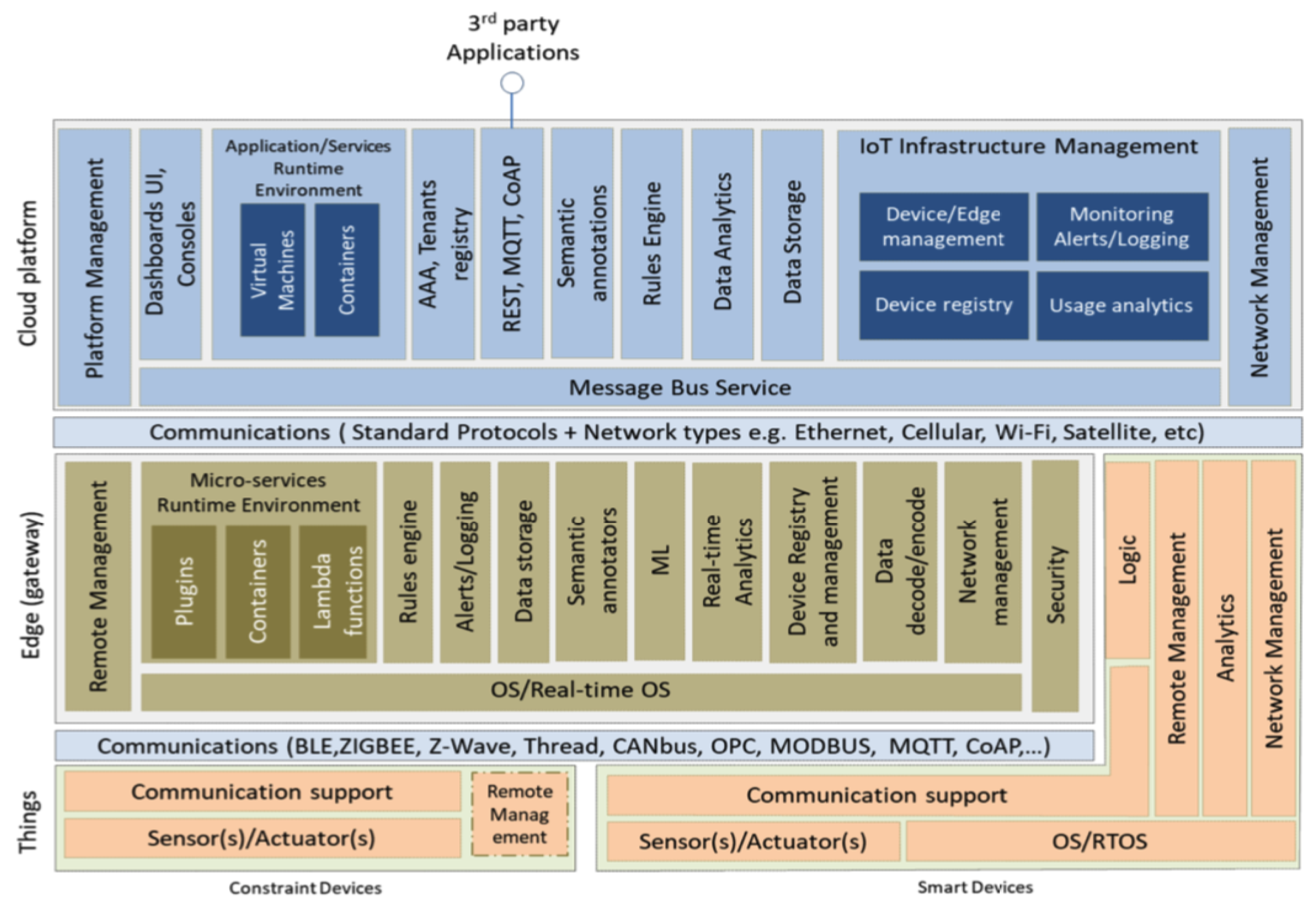
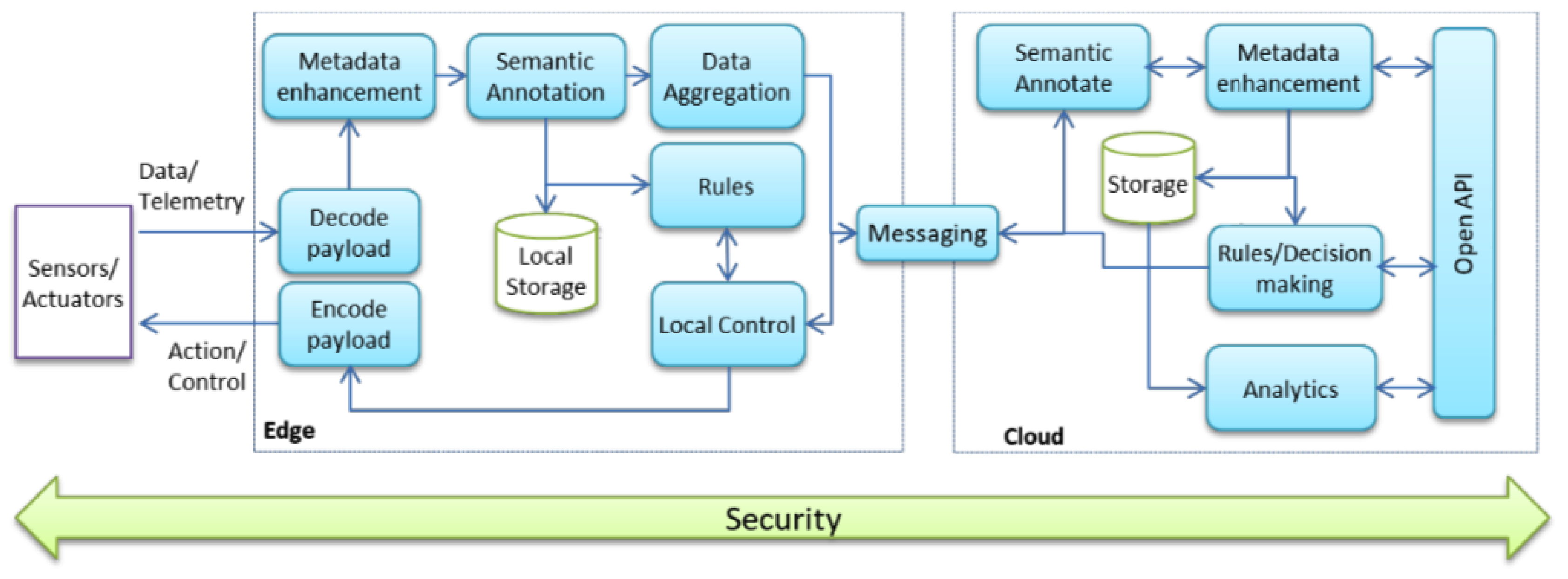
3.1. System Architecture
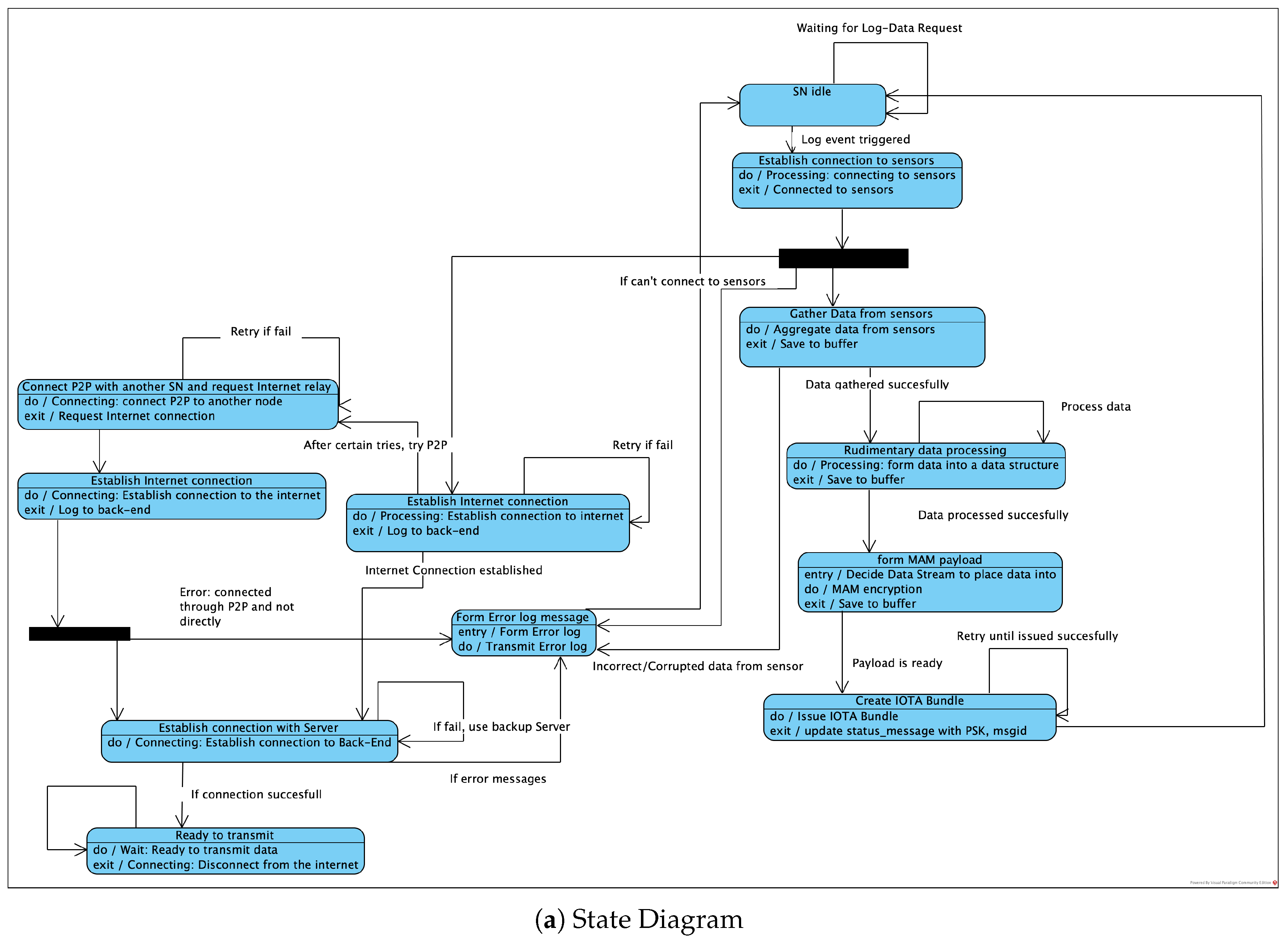
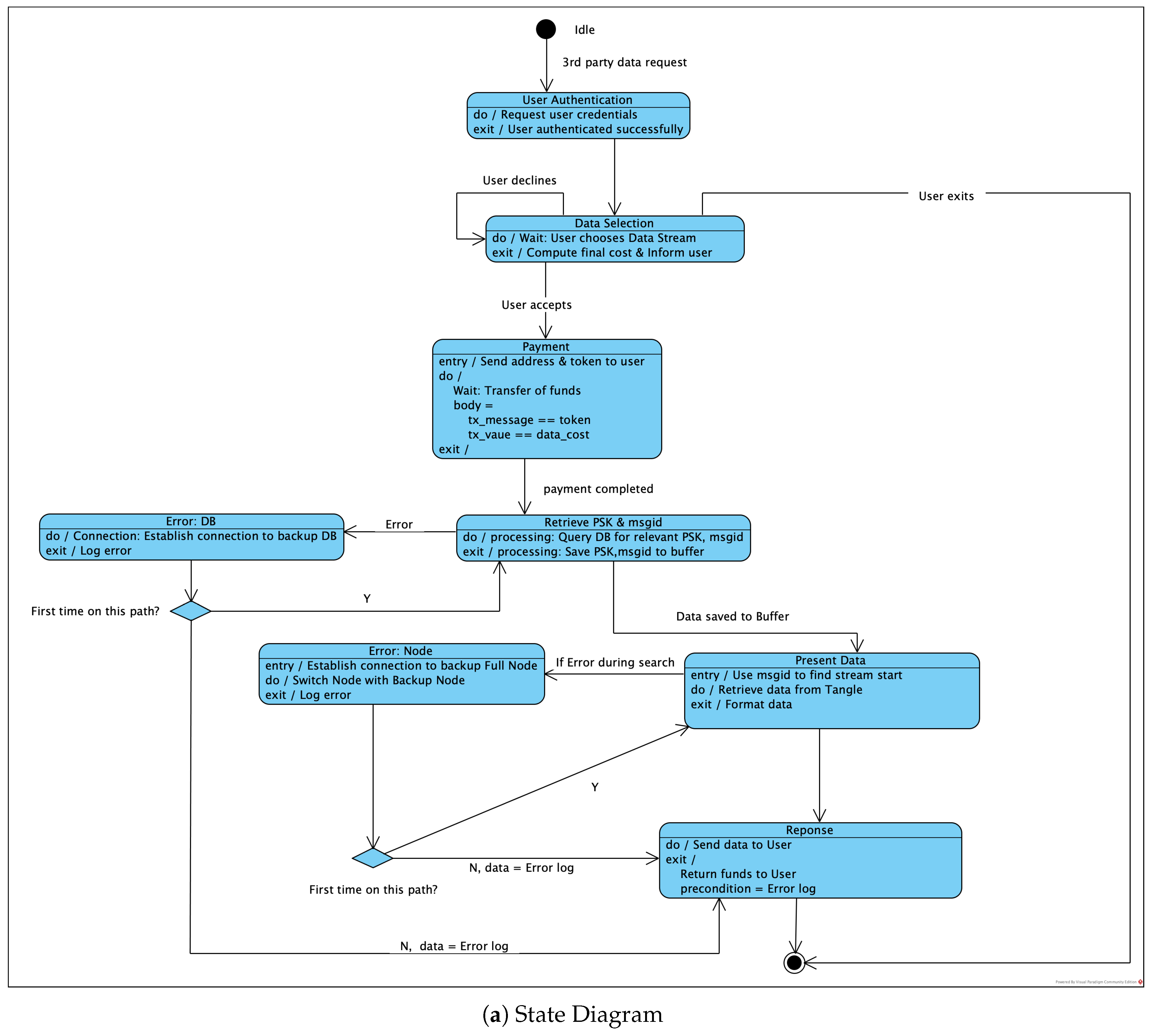
3.2. Envisioned Core Activities
3.3. Architecture Metrics
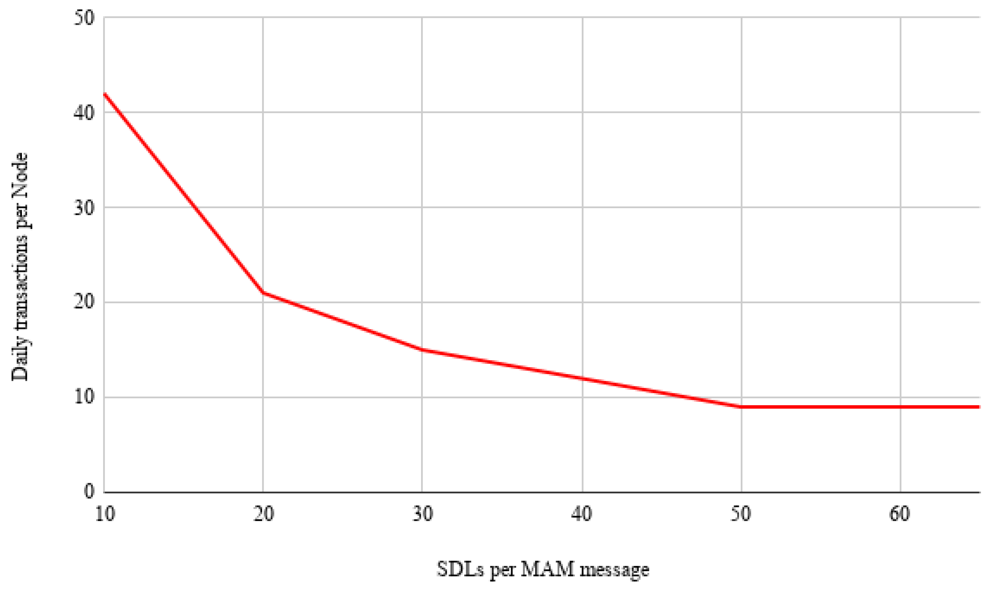
- Iota Transaction throughput
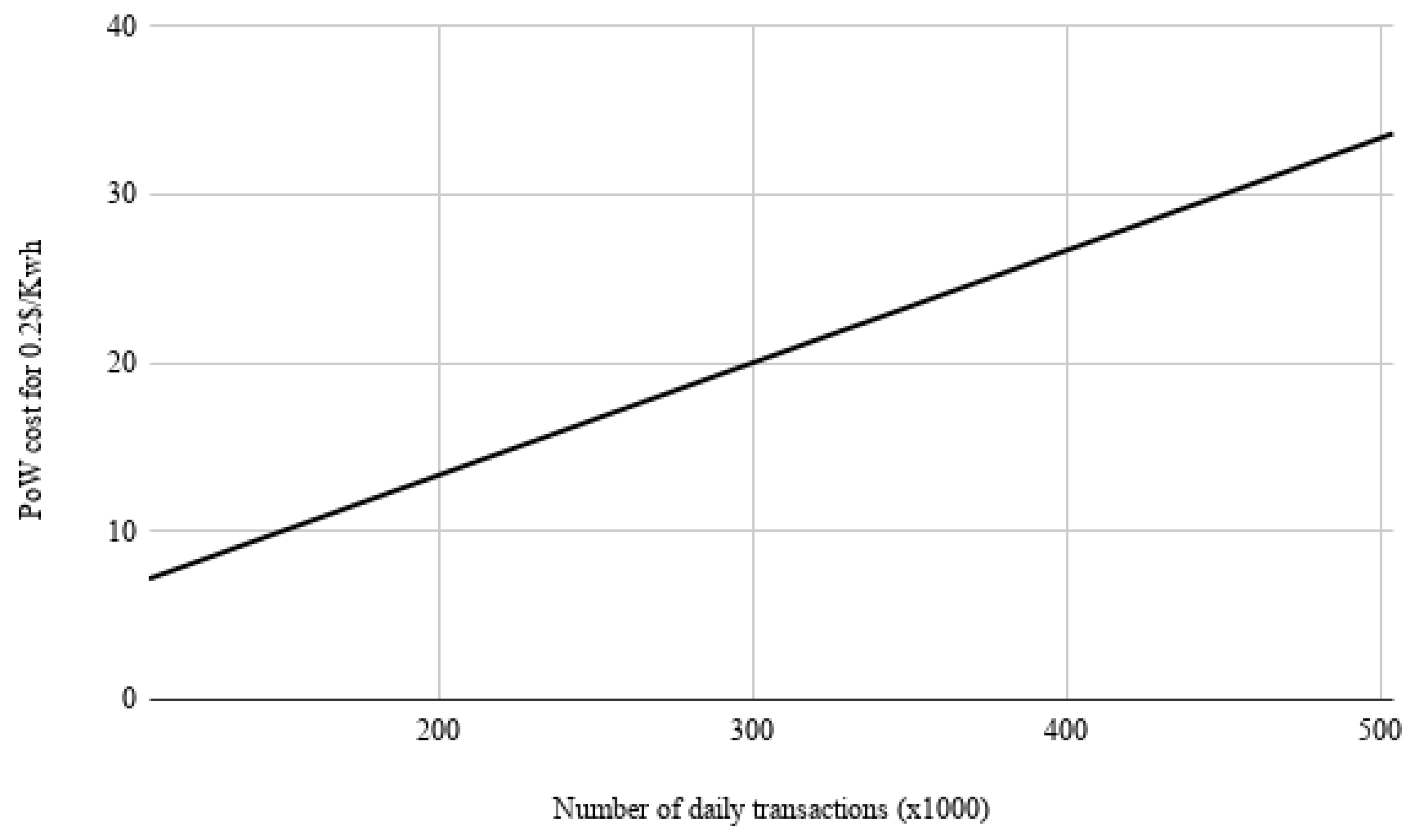
- PoW
4. Results
4.1. System Implementation
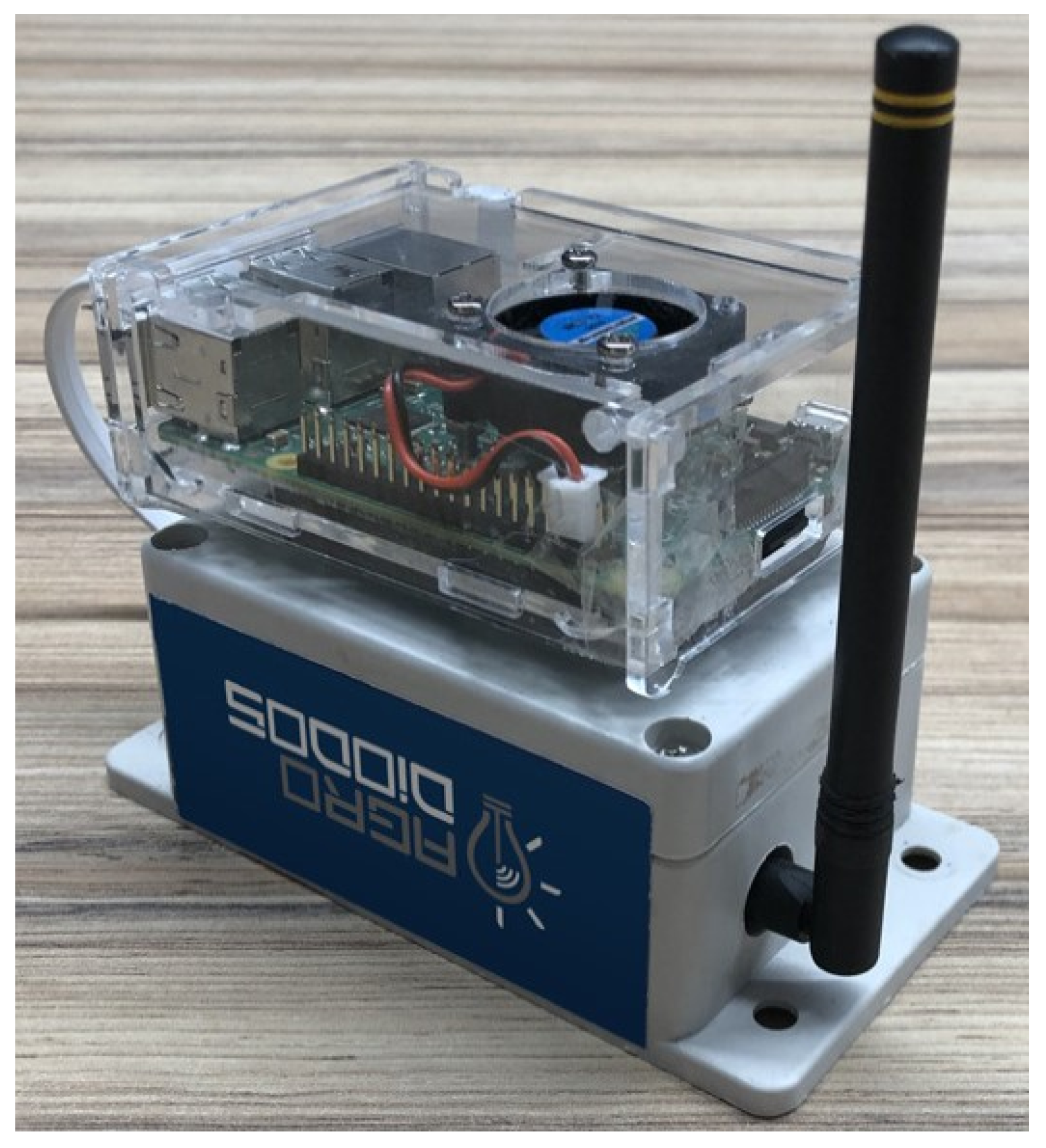
- Coverage Distance: The maximum, transmission distance is a function of antenna power, frequency and transmission speed. For 868 MHz radio frequency, 1Kbps transmission speed and 10dbm antenna power, a 12.5 km line of sight has been achieved. For a 433 MHz frequency the distance is doubled. The transmitter and receiver use antennas of half wave 1.2 dBi peak gain. In case the topology requires it, IoT nodes are used as repeaters (with minor modifications to the firmware).
- Energy Consumption Hibernate mode is the dominant mode for the IoT node since the total consumption in this state is 6 A. During broadcast, for output power of 10 dbm in the antenna, the consumption is 32 mA. Fifteen (15) levels of output power are available, while the transmission speed can be selected from a range of 1Kbps to 300 Kbps. Therefore, for a 20 bytes transmission packet every ten (10) min with maximum antenna power and 1 Kbps transmission rate, the average power consumption of the IoT node is approximately 22 A and its 650 mAh battery could endure for approximately 3.5 years. The node’s battery will be recharged through the photovoltaic panel which allows the battery to fully charge within 20 h of exposure to solar radiation.
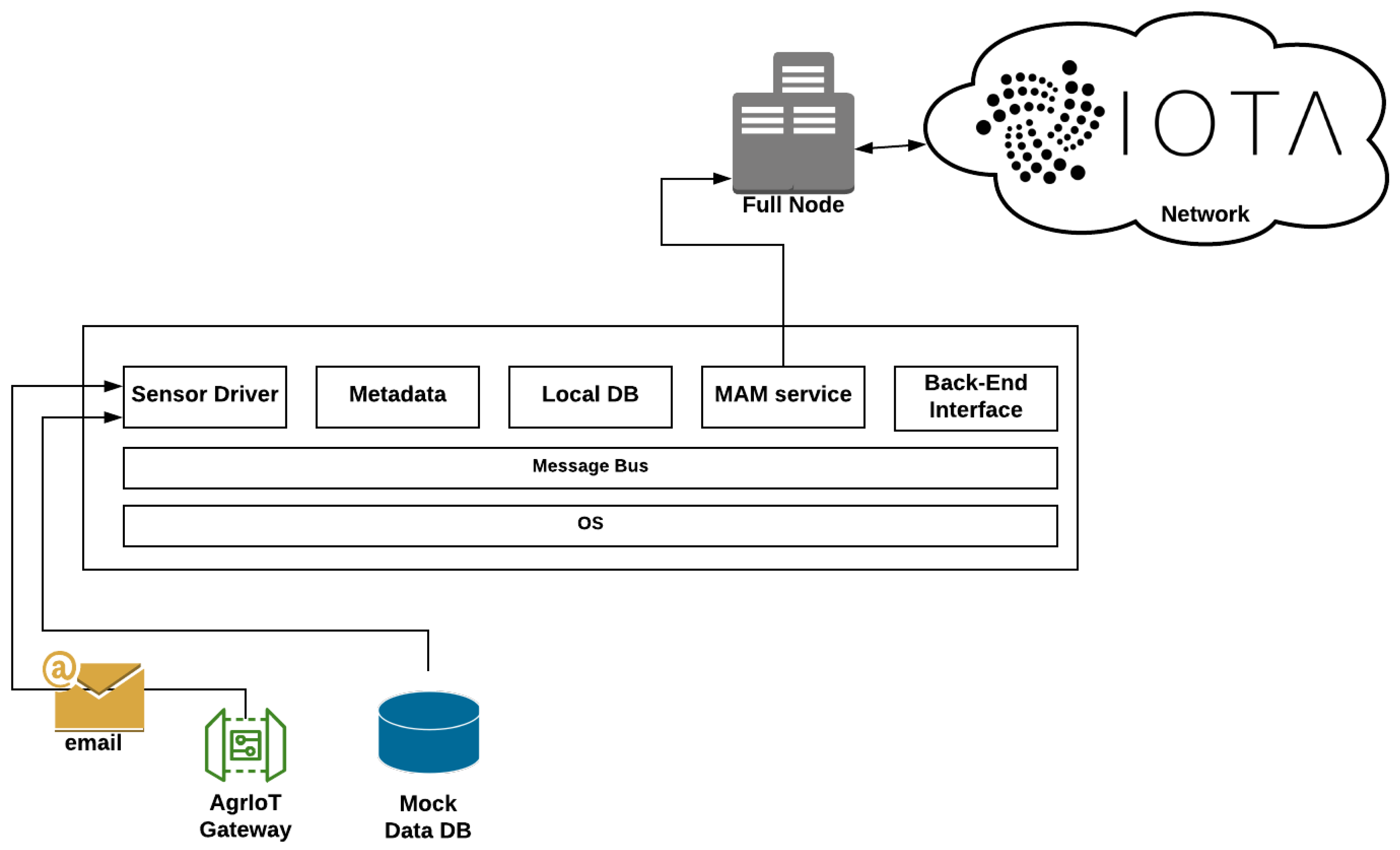
4.2. Edge Node and Cloud System Modules
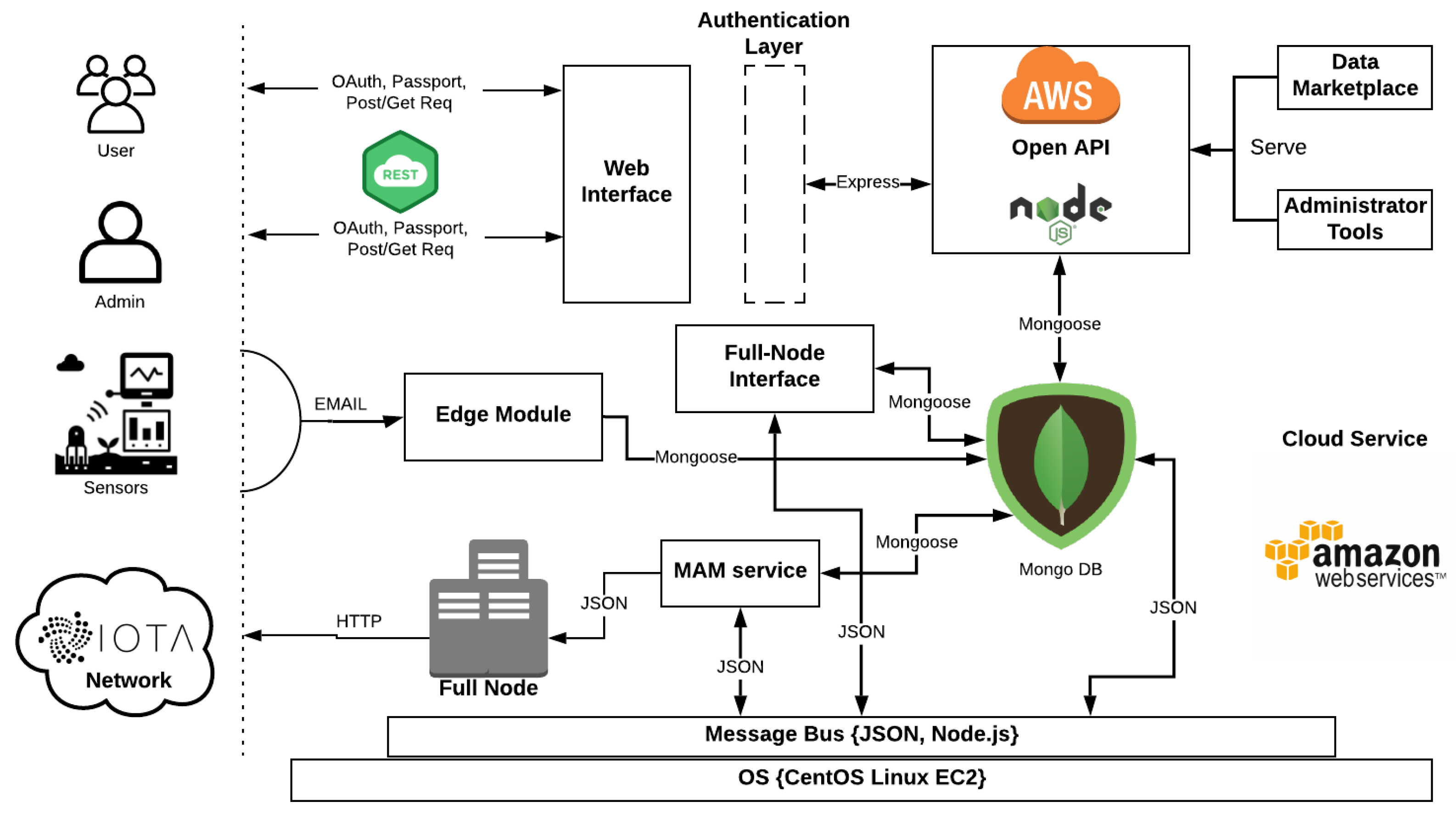
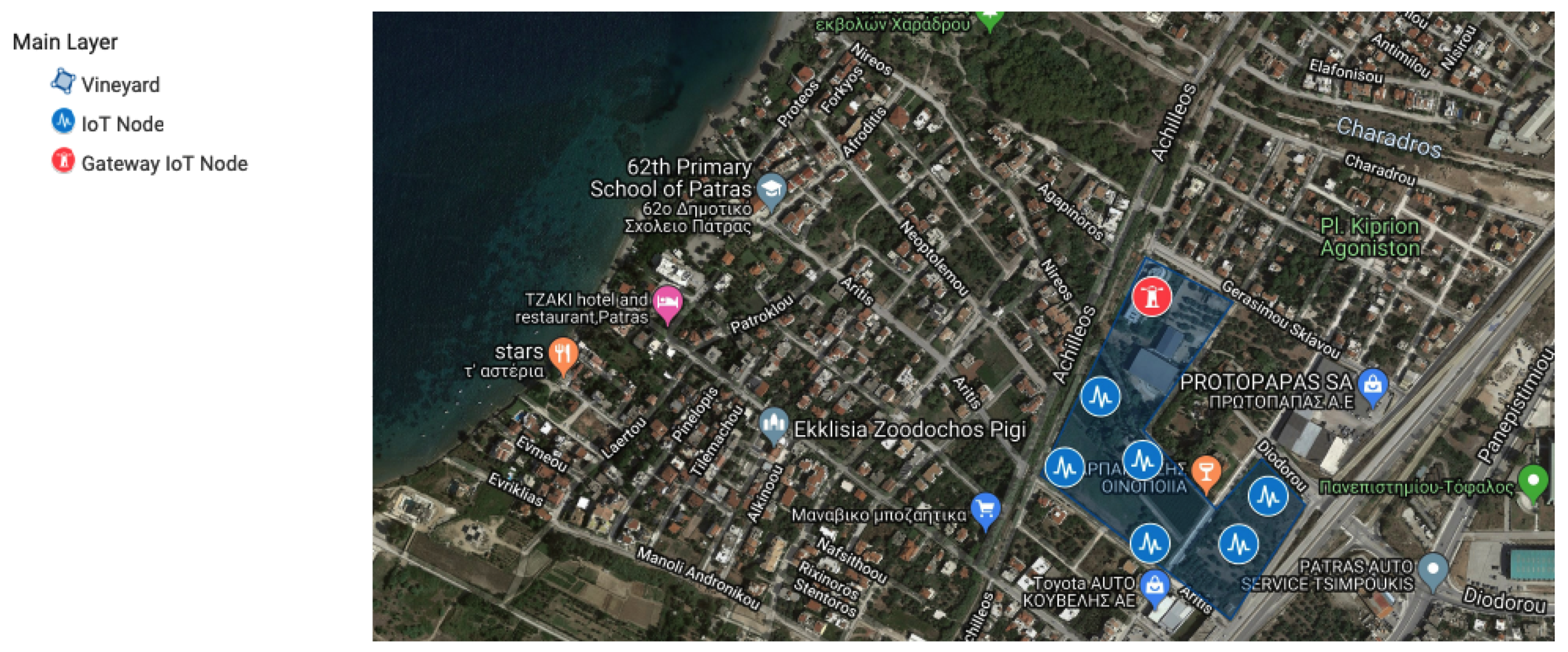
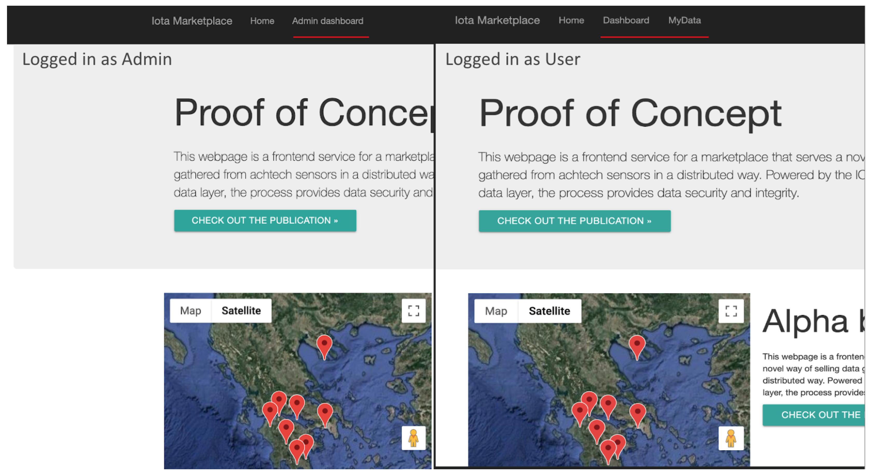
- Edge Module: The edge Module provides, through an HTTP connection paired with an extra security key, the ability of the system to accept and update the sensor pool. The edge interface also maintains, when needed, a Mongoose powered connection to the system’s Local Database with a unique and secure Open Authentication (Oauth) key pair combination that is kept internally and is defined during the system initialization. When a new sensor data log is introduced to the system, after it passes a sanitisation phase, it is imported through a POST request into the Database. It is then able to be served by the Backend interface to the user through the normal procedure. Every sensor that belongs to a field, is paired with that field using a corresponding unique field id and each field is showcased through the Google Maps API in the map on the front-end main view. Figure 19 showcases the Admin/User Authentication Layer, which through passport and PUG front end template engine ensures that the user and admin level actions are distinguished both visually and internally.
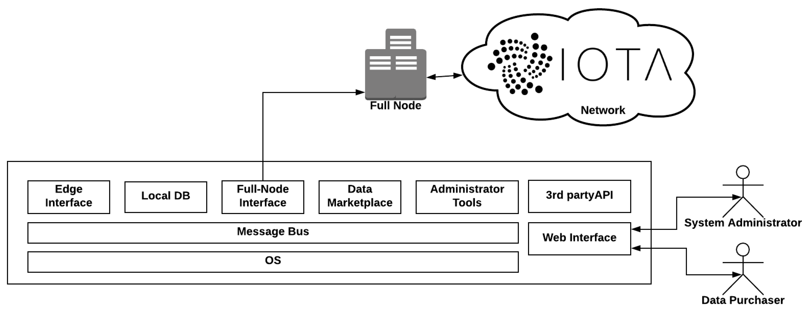
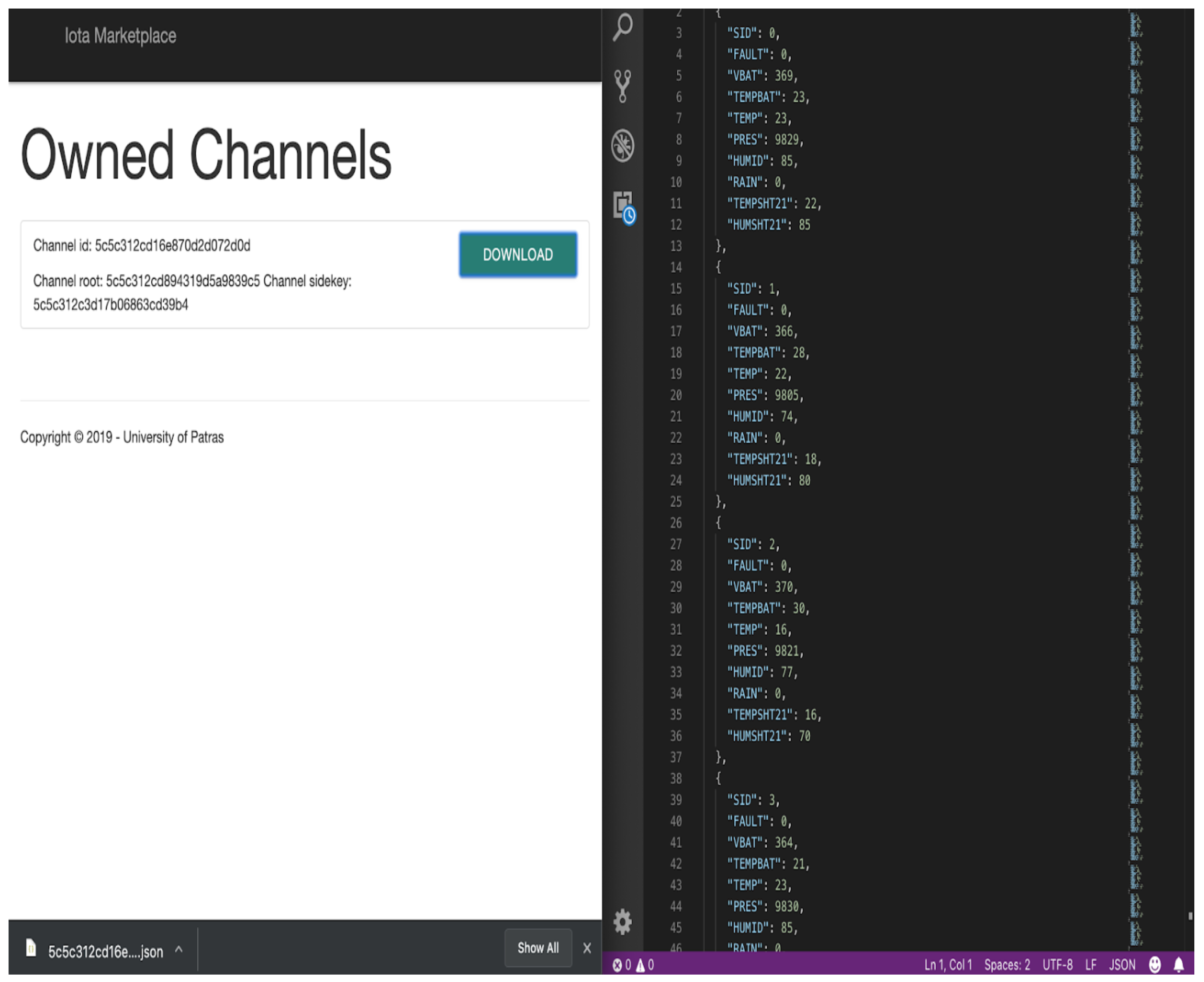
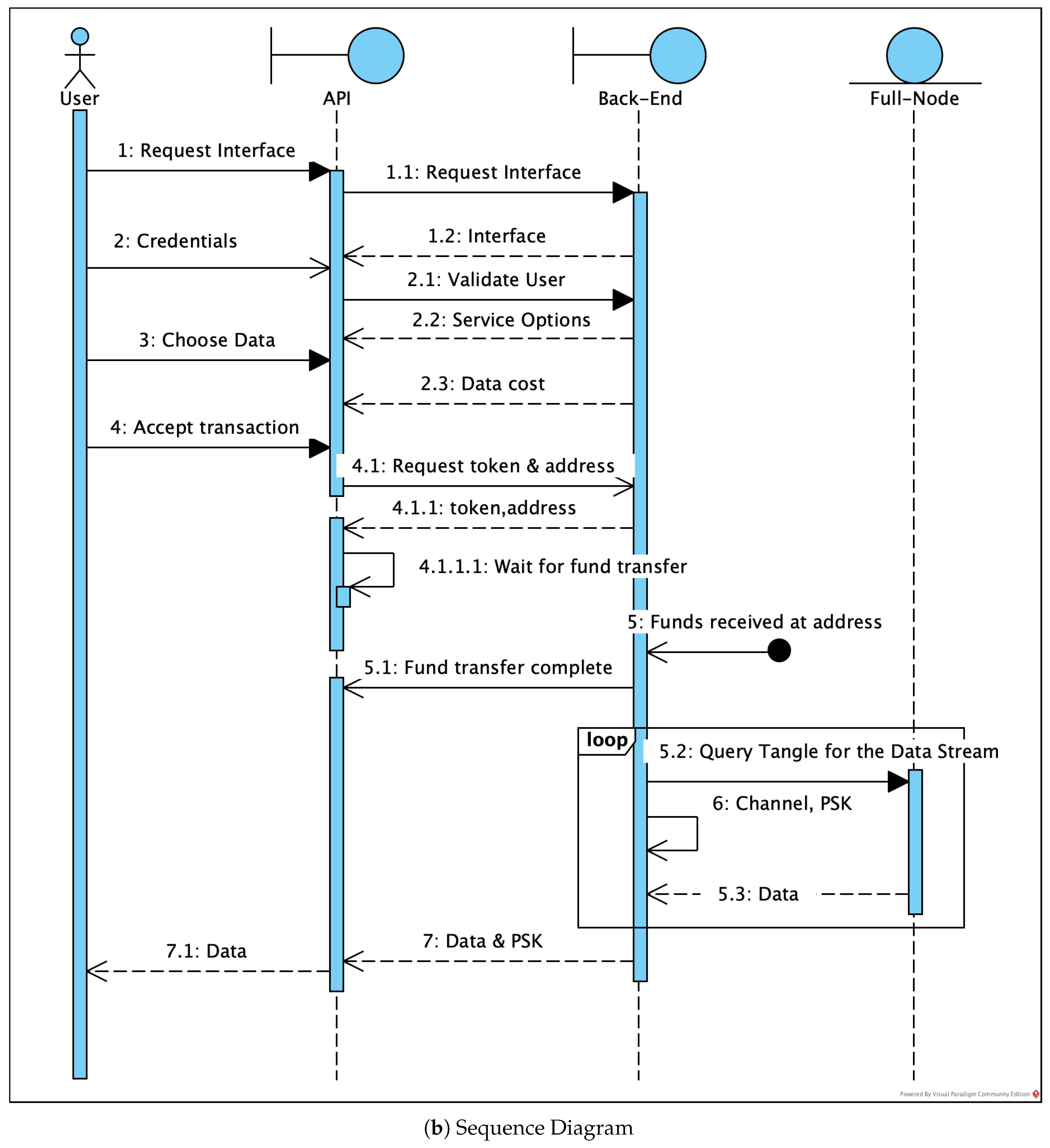
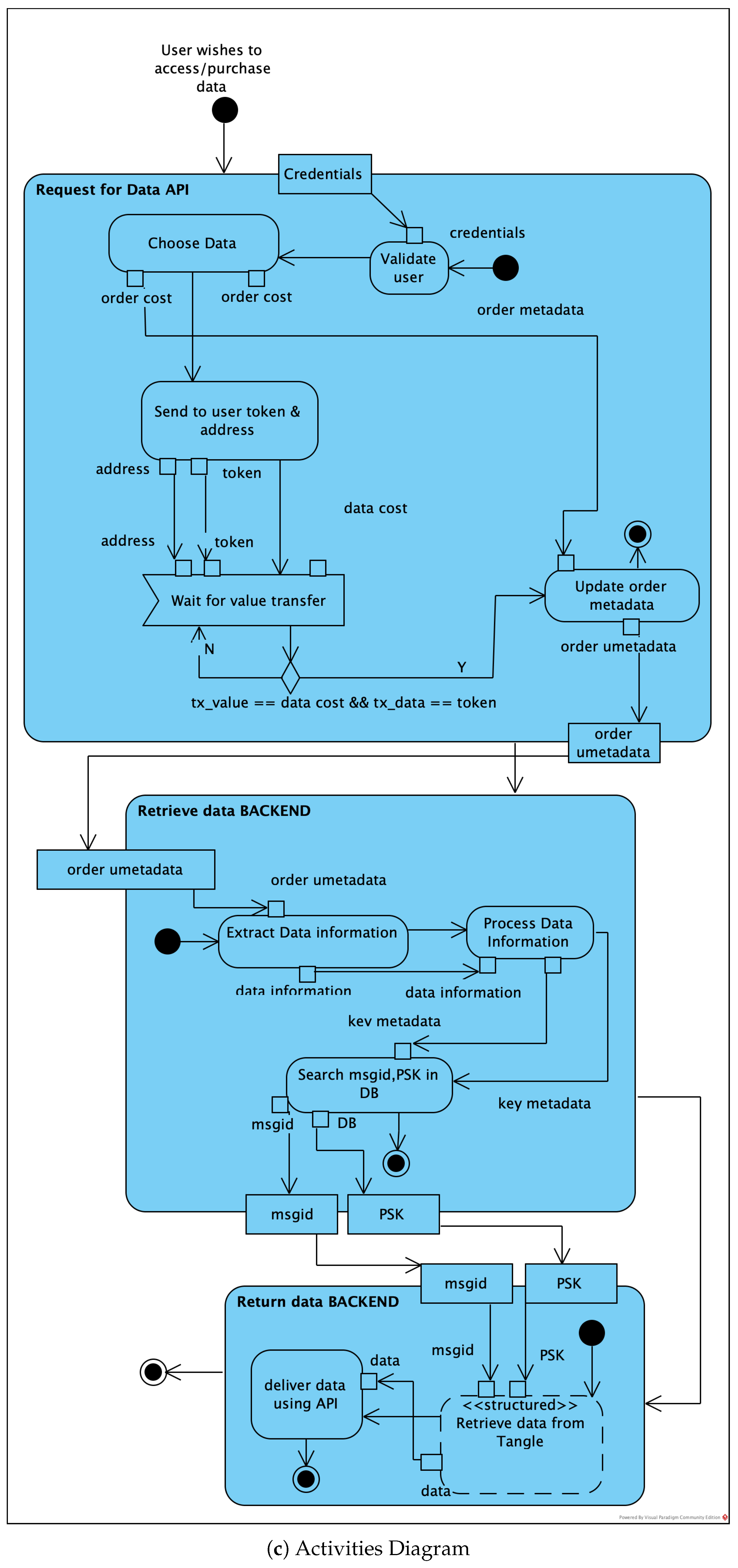
- IOTA Full Node Interface: The IOTA Full Node interface interacts with the IOTA network, through the IOTA DevNet servers that act as IOTA Full-Nodes (FN). When an order is placed by a customer through the Front-End interface, a unique order ID is created and an Oauth confirmation code is served to the user. The user can then place their payment in the corresponding address that is provided, with the confirmation code on the message of the transaction. Additionally, a pending order entry is created via a post request in the database and is showcased to the user. When an order is placed, the IOTA Full Node Interface module that checks for new transactions handles the inbound transaction and cross-checks the Oauth verification key. If the keys match, the pending order is accepted and the corresponding data are handed to the user via My Data view on the front end. As Figure 20 depicts, the user can then download the data.
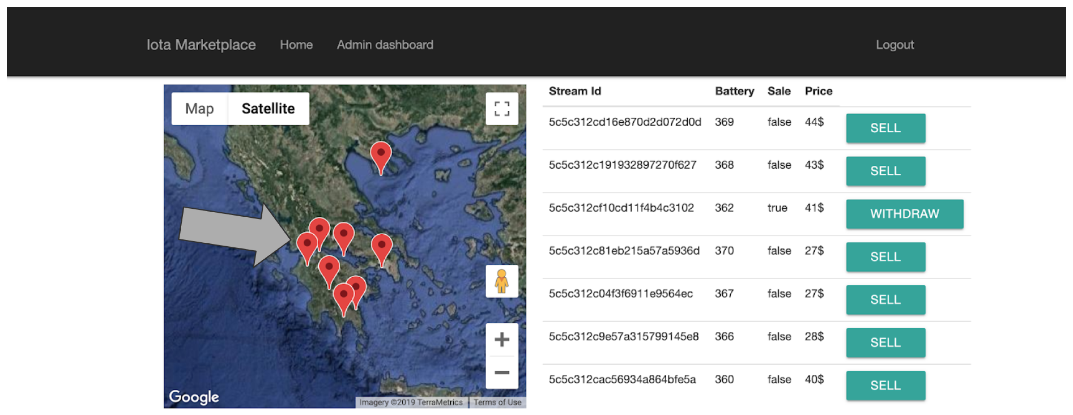
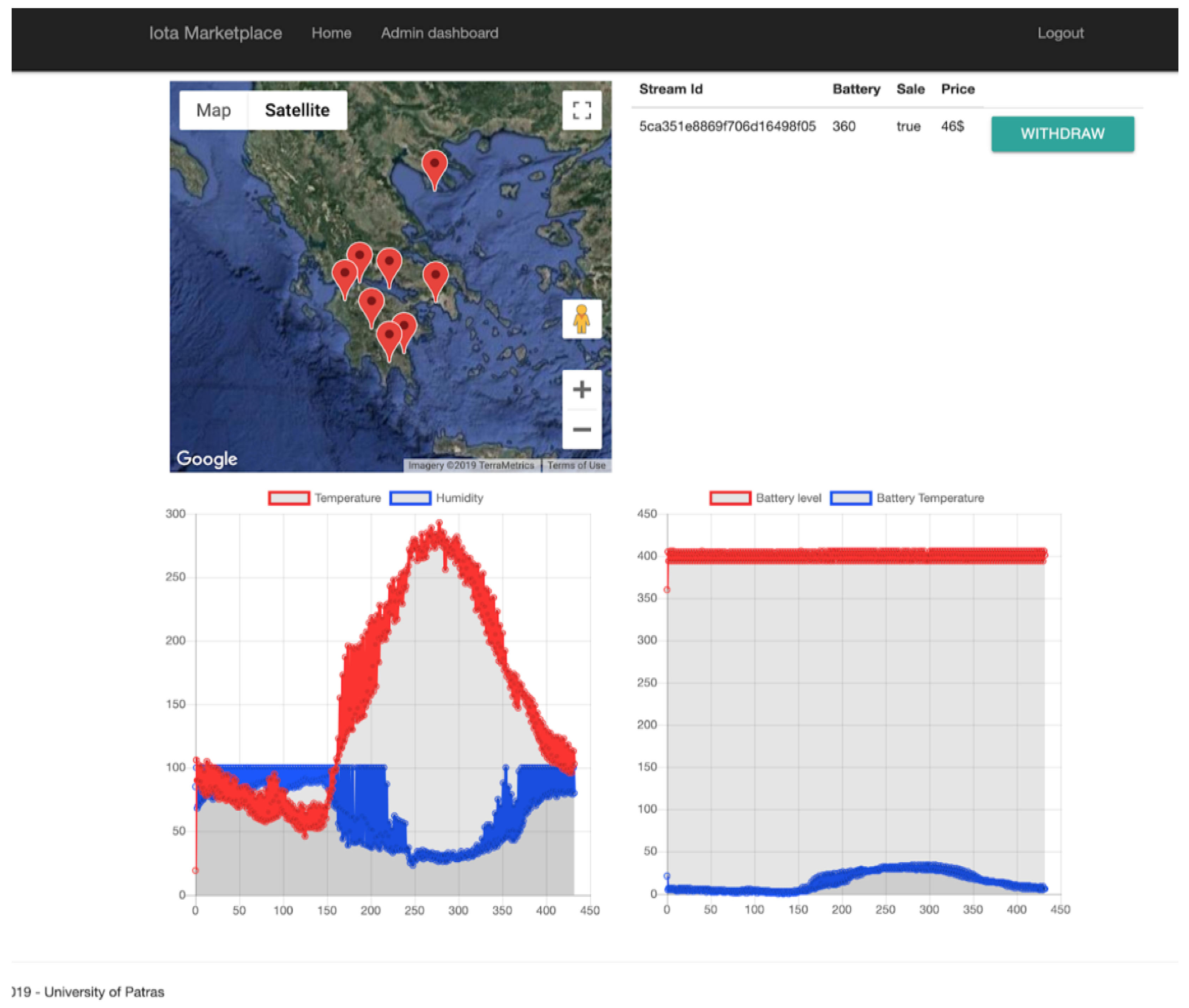
- Administrator Tools: The administrator tools provide a Backend insight for the system administrator to interact with the data streams that are provided in the platform. The availability of the data is set through the ““UPDATE” functions as shown in Figure 21, while the views are provided by Chart.js [44] as shown in Figure 22.
- Cloud Technology: The entirety of the backend server and the local NoSQL database is uploaded in an AWS EC2 cloud service and runs on a CENTOS Linux Virtual machine. This service is chosen since it provides the necessary functionality to serve as a proof of concept system, while it also has the capability to scale up in the future, keeping up with the market’s needs. Any system updates are pushed through Git that is installed locally and the data uplink from the live sensors can be linked through a post request with a secret key ensuring that the source providing the data is verified.
- Sensor Driver: When a sensor is imported into the system, the sensor driver service runs the driver initialization function in order to update the setup, the interface and register the sensor details into the database. During the initialization, the driver runs preliminary checks ensuring sensors’s health and stability, with the run_preliminary_routines() function. It also uses the check_statistics() function in order to display sensor logging and performance information regarding all its vitals and other statistics regarding use, install date, etc. Finally, with the import_sensor_to_db() function, the sensor is incorporated into the system and marked available for use. Since the data are aggregated using an email client, the current sensor driver implementation is for reference only.
- MAM Service: This service provides a structure of functions that handles the data through the MAM data layer such as the initialization of the public chain (_public_chain()) or the addition of a channel to an existing chain append_channel_to_chain(). When the service interacts with the database by establishing a secure connection through the mongoose API. For the Merkle tree generation, the service shall utilize the generate_merkle_tree() function. To trace a corresponding channel in the database, a query is executed and the response is fed to the corresponding function fetch_from_Tangle().
- Database Service: This service facilitates the connection with the MongoDB database and the handling of the data before their incorporation to the system. This service uses the semantic_filtering() function to filter, label and export in JSON format the sanitized data. There are also functions for data cleaning, aggregation, back up and maintenance. The data flow within the Node.Js powered backend server is facilitated through JSON files, thus maintaining the integrity of the structure of the data and the ease of use.
- Web Interface The user interface is generated by PUG engine which is a predecessor of JADE. PUG, in essence, enables the generation of dynamic and reusable HTML documents, while the incorporation of the modern Bootstrap CSS framework results into a minimalistic user experience that maintains the structural modularity required for a multi view/authentication-layer website. The map provided in the home page, is powered by Google development platform and the corresponding graphs in the administration panel are generated by parsing the available data through JQuery and showcasing through Chart.js, while with different authentication layers provided by Passport.js the user can see their corresponding available sub views. Any of the unavailable pages (such as the administration panel for the users) are protected with the same library. The front end interface is modular and expandable.
5. Verification and Small-Scale Demonstration
5.1. General
5.2. Implemented Activities in the Use Cause
5.3. Application Use Case Description
6. Discussion
7. Conclusions
Author Contributions
Funding
Conflicts of Interest
References
- Lamtzidis, O.; Gialelis, J. An IOTA Based Distributed Sensor Node System. In Proceedings of the 2018 IEEE Globecom Workshops (GC Wkshps), Abu Dhabi, UAE, 9–13 December 2018; pp. 1–6. [Google Scholar] [CrossRef]
- The Next Generation of Distributed Ledger Technology|IOTA. Available online: https://www.iota.org/ (accessed on 28 June 2019).
- Yonatan, S.; Lewenberg, Y.; Zohar, A. SPECTRE: A Fast and Scalable Cryptocurrency Protocol. IACR Cryptol. ePrint Arch. 2016, 2016, 1159. [Google Scholar]
- Sompolinsky, Y.; Zohar, A. Phantom, Ghostdag. Available online: https://eprint.iacr.org/2018/104.pdf (accessed on 29 June 2019).
- Serguei, P. The Tangle. Available online: https://assets.ctfassets.net/r1dr6vzfxhev/2t4uxvsIqk0EUau6g2sw0g/45eae33637ca92f85dd9f4a3a218e1ec/iota1_4_3.pdf (accessed on 29 June 2019).
- Home|IOTA Documentation. Available online: https://docs.iota.org/ (accessed on 28 June 2019).
- Johannes, B.; Dahmen, E.; Ereth, S.; Hülsing, A.; Rückert, M. On the security of the Winternitz one-time signature scheme. In Proceedings of the International Conference on Cryptology in Africa, Dakar, Senegal, 5–7 July 2011; Springer: Berlin/Heidelberg, Germany, 2011; pp. 363–378. [Google Scholar]
- MAM2 Specification. Available online: https://github.com/iotaledger/entangled/blob/develop/mam/spec.pdf (accessed on 29 June 2019).
- Johannes, B.; García, L.C.C.; Dahmen, E.; Döring, M.; Klintsevich, E. CMSS—An improved Merkle signature scheme. In Proceedings of the International Conference on Cryptology in India, Kolkata, India, 11–13 December 2006; Springer: Berlin/Heidelberg, Germany, 2006; pp. 349–363. [Google Scholar]
- Jeffrey, H.; Pipher, J.; Silverman, J.H. NTRU: A ring-based public key cryptosystem. In Proceedings of the International Algorithmic Number Theory Symposium, Portland, OR, USA, 21–25 June 1998; Springer: Berlin/Heidelberg, Germany, 1998; pp. 267–288. [Google Scholar]
- Protocol Buffers Version 2 Language Specification|Protocol Buffers|Google Developers. Available online: https://developers.google.com/protocol-buffers/docs/reference/proto2-spec (accessed on 28 June 2019).
- Jesse, Y.; Ko, D.; Choi, S.; Park, S.; Smolander, K. Where is current research on blockchain technology?—A systematic review. PLoS ONE 2016, 11, E0163477. [Google Scholar]
- Satoshi, N. Bitcoin: A Peer-to-Peer Electronic Cash System. Available online: https://bitcoin.org/bitcoin.pdf (accessed on 29 June 2019).
- Salomaa, A. Public-Key Cryptography; Springer Science & Business Media: Berlin/Heidelberg, Germany, 2013. [Google Scholar]
- Joseph, B.; Miller, A.; Clark, J.; Narayanan, A.; Kroll, J.A.; Felten, E.W. Sok: Research perspectives and challenges for bitcoin and cryptocurrencies. In Proceedings of the 2015 IEEE Symposium on Security and Privacy, San Jose, CA, USA, 17–21 May 2015; pp. 104–121. [Google Scholar]
- Blockchain Architecture: The Basics|Pluralsight. Available online: https://www.pluralsight.com/guides/blockchain-architecture (accessed on 28 June 2019).
- Buterin, V. Ethereum: A Next-Generation Smart Contract and Decentralized Application Platform. Available online: https://github.com/ethereum/wiki/wiki/White-Paper (accessed on 28 June 2019).
- Li, X.; Jiang, P.; Chen, T.; Luo, X.; Wen, Q. A survey on the security of blockchain systems. Future Gener. Comput. Syst. 2017, in press. [Google Scholar] [CrossRef]
- EOSIO—Blockchain Software Architecture. Available online: https://eos.io/ (accessed on 29 June 2019).
- Zheng, Z.; Xie, S.; Dai, H.; Chen, X.; Wang, H. An overview of blockchain technology: Architecture, consensus, and future trends. In Proceedings of the 2017 IEEE International Congress on Big Data (BigData Congress), Honolulu, HI, USA, 25–30 June 2017; pp. 557–564. [Google Scholar]
- Hyperledger Fabric—Hyperledger. Available online: https://www.hyperledger.org/projects/fabric (accessed on 29 June 2019).
- Genuino 101. Available online: https://store.arduino.cc/genuino-101 (accessed on 29 June 2019).
- Orange Pi—Orangepi. Available online: http://www.orangepi.org/ (accessed on 29 June 2019).
- Raspberry pi Home-page. Available online: https://www.raspberrypi.org/ (accessed on 29 June 2019).
- CoAP—Constrained Application Protocol|Overview. Available online: http://coap.technology/ (accessed on 29 June 2019).
- MQTT. Available online: http://mqtt.org/ (accessed on 29 June 2019).
- RFC 1081—Post Office Protocol: Version 3. Available online: https://tools.ietf.org/html/rfc1081 (accessed on 29 June 2019).
- Gialelis, J.; Gerasimos, T.; Maria, F.; Dimitrios, K. An Integrated Low Cost IoT Node based on Discrete Components for Customized Smart Applications; Use case on Precision Agriculture. In Proceedings of the 2019 8th Mediterranean Conference on Embedded Computing (MECO), Budva, Montenegro, 10–14 June 2019. [Google Scholar]
- Khan, R.; Khan, S.U.; Zaheer, R.; Khan, S. Future internet: The internet of things architecture, possible applications and key challenges. In Proceedings of the 2012 10th International Conference on Frontiers of Information Technology, Islamabad, India, 17–19 December 2012; pp. 257–260. [Google Scholar]
- Internet of Things Forecast—Ericsson Mobility Report. Available online: https://www.ericsson.com/en/mobility-report/internet-of-things-forecast (accessed on 29 June 2019).
- Kshetri, N. Can blockchain strengthen the internet of things? IT Prof. 2017, 19, 68–72. [Google Scholar] [CrossRef]
- Report from the Commission: Benchmarking Smart Metering Deployment in the EU-27 with a Focus on Electricity. Available online: https://ec.europa.eu/energy/en/topics/markets-and-consumers/smart-grids-and-meters (accessed on 29 June 2019).
- Library, C. Flint Water Crisis Fast Facts. Available online: https://edition.cnn.com/2016/03/04/us/flint-water-crisis-fast-facts/index.html (accessed on 29 June 2019).
- Conoscenti, M.; Vetro, A.; Martin, J.C.D. Blockchain for the Internet of Things: A systematic literature review. In Proceedings of the 2016 IEEE/ACS 13th International Conference of Computer Systems and Applications (AICCSA), Agadir, Morocco, 29 November–2 December 2016; pp. 1–6. [Google Scholar]
- Dorri, A.; Kanhere, S.S.; Jurdak, R.; Gauravaram, P. Blockchain for IoT security and privacy: The case study of a smart home. In Proceedings of the 2017 IEEE International Conference on Pervasive Computing and Communications Workshops (PerCom Workshops), Kona, HI, USA, 13–17 March 2017; pp. 618–623. [Google Scholar]
- Micro-Insurance for Small Farmers—This Amazing Idea Is Changing Lives for Farmers in East Africa (Must Watch!)—Smallstarter Africa. Available online: https://www.smallstarter.com/get-inspired/micro-insurance-for-small-farmers-in-africa/ (accessed on 29 June 2019).
- Qubic: Details on 03-06-2018. Available online: https://qubic.iota.org/ (accessed on 29 June 2019).
- Tranoris, C. Open Source Software Solutions Implementing a Reference IoT Architecture from the Things and Edge to the Cloud; University of Patras: Patras, Greece, 2018. [Google Scholar] [CrossRef]
- Access Tokens. Available online: https://auth0.com/docs/tokens/overview-access-tokens (accessed on 2 September 2019).
- IOTA Tangle Explorer and Statistics—TheTangle.org. Available online: https://thetangle.org/ (accessed on 2 September 2019).
- Thomas Pototschnig/Pidiver1.3. Available online: https://gitlab.com/microengineer18/pidiver1.3 (accessed on 2 September 2019).
- DLTcollab/Dcurl. Available online: https://github.com/DLTcollab/dcurl (accessed on 2 September 2019).
- Proof of Concept Codebase|Github. Available online: https://github.com/OdysLam/iota_paper_codebase (accessed on 29 June 2019).
- Chart.js|Open Source HTML5 Charts for Your Website. Available online: https://www.chartjs.org/ (accessed on 29 June 2019).
- Instant & Feeless—Flash Channels. Available online: https://blog.iota.org/instant-feeless-flash-channels-88572d9a4385 (accessed on 29 June 2019).
- Coordinator-Part-1: The-Path-to-Coordicide. Available online: https://blog.iota.org/coordinator-part-1-the-path-to-coordicide-ee4148a8db08 (accessed on 29 June 2019).
- Wall, E. IOTA is Centralized. Available online: https://medium.com/@ercwl/iota-is-centralized-6289246e7b4d (accessed on 29 June 2019).
- Heilman, E.; Narula, N.; Tanzer, G.; Lovejoy, J.; Colavita, M.; Virza, M.; Dryja, T. Cryptanalysis of Curl-P and Other Attacks on the IOTA Cryptocurrency. IACR Cryptol. ePrint Arch. 2019, 2019, 344. [Google Scholar]
- Official IOTA Foundation Response to the Digital Currency Initiative at the MIT Media Lab. Available online: https://blog.iota.org/official-iota-foundation-response-to-the-digital-currency-initiative-at-the-mit-media-lab-part-4-11fdccc9eb6d (accessed on 29 June 2019).


| Sensor and Scope |
|---|
| Humidity, Temperature, Pressure and Ambient H, T, P |
| Rain Amount and Rain |
| Leaf Wetness and Leaf |
| Soil Moisture and Soil |
| Wind Speed, Direction and Wind |
| Solar Radiation and Pyranometer |
© 2019 by the authors. Licensee MDPI, Basel, Switzerland. This article is an open access article distributed under the terms and conditions of the Creative Commons Attribution (CC BY) license (http://creativecommons.org/licenses/by/4.0/).
Share and Cite
Lamtzidis, O.; Pettas, D.; Gialelis, J. A Novel Combination of Distributed Ledger Technologies on Internet of Things: Use Case on Precision Agriculture. Appl. Syst. Innov. 2019, 2, 30. https://doi.org/10.3390/asi2030030
Lamtzidis O, Pettas D, Gialelis J. A Novel Combination of Distributed Ledger Technologies on Internet of Things: Use Case on Precision Agriculture. Applied System Innovation. 2019; 2(3):30. https://doi.org/10.3390/asi2030030
Chicago/Turabian StyleLamtzidis, Odysseas, Dennis Pettas, and John Gialelis. 2019. "A Novel Combination of Distributed Ledger Technologies on Internet of Things: Use Case on Precision Agriculture" Applied System Innovation 2, no. 3: 30. https://doi.org/10.3390/asi2030030
APA StyleLamtzidis, O., Pettas, D., & Gialelis, J. (2019). A Novel Combination of Distributed Ledger Technologies on Internet of Things: Use Case on Precision Agriculture. Applied System Innovation, 2(3), 30. https://doi.org/10.3390/asi2030030