1. Introduction
The behavior of droplets dispersed in the liquid phase has great importance in many diverse industrial and technological applications, such as extraction of liquid-liquid mixtures or emulsions formation, waste-water treatment or hydrometallurgy. Efficiency of many of these applications can be investigated and partially predicted on the basis of results of fundamental studies related to the hydrodynamics of single droplets in a liquid phase. In laboratory practice, for proper experimental investigations of rising droplet hydrodynamics as well as collisions between droplets and formation of single emulsion films under dynamic conditions, control over the formation of a single droplet with the desired diameter and detachment frequency is of crucial importance.
Nowadays, microfluidic devices, for which fabrication and modification has been extensively studied and described [
1,
2,
3,
4,
5,
6], are the most widely used for single droplet generation in a liquid phase. In such devices two immiscible liquids are pumped through microchannels, where one phase is dispersed in the other. For the sake of efficient device design and control on the size and monodispersity of generated microdroplets, many researchers have investigated various microfluidic methods of droplet generation both experimentally and numerically [
1,
2,
3,
4,
5,
6,
7,
8,
9,
10,
11,
12,
13,
14,
15,
16]. According to the mechanism of dispersion, microfluidics devices can be divided into three groups: devices where a droplet is formed as a result of (i) breakup in co-flowing streams [
4,
5,
7,
10]; (ii) breakup in cross-flowing streams (T-junction) [
9,
10,
11,
12]; and (iii) breakup in elongational strained flows (flow-focusing) [
14,
15,
16]. The undoubted advantage of microfluidic devices (called microchips) is their ability to generate single droplets with micrometer size. Furthermore, such devices are usually small and handy. However, the size range of generated droplets depends on the microchannels diameter. Moreover, the microchannels diameter affects a single droplet velocity inside the channel as a result of droplet-wall interactions [
1,
5,
9,
17,
18,
19]. Droplet size strictly depends on microchannel geometry (for example channel length, nozzle to orifice distance etc.) [
5], which should be precisely controlled for sufficient repeatability of the results. In addition, the microchips have limited mechanical durability and defined shape, which limits its applicability in laboratory experiments concerning the motion of a single droplet from the very beginning of its formation and acceleration in liquid column.
The paper presents an alternative methodology of single droplet generation in the liquid phase. We have developed a quite simple, fully automatic single droplet generator, allowing precise control over the single droplet diameter and detachment frequency. Our automatized generator allows formation of droplets in quite wide range of diameters with very good precision without need of orifice diameter replacements. Moreover, the time available for adsorption of surface active-substances over the immobilized droplet, before its detachment from the orifice, can be precisely and easily controlled, as well as the degree of adsorption coverage at liquid/liquid interface. This feature is important especially for investigations of stability of single emulsion films formed under dynamic conditions (kinetics of droplet coalescence).
2. Materials and Methods
2.1. Experimental Set-Up
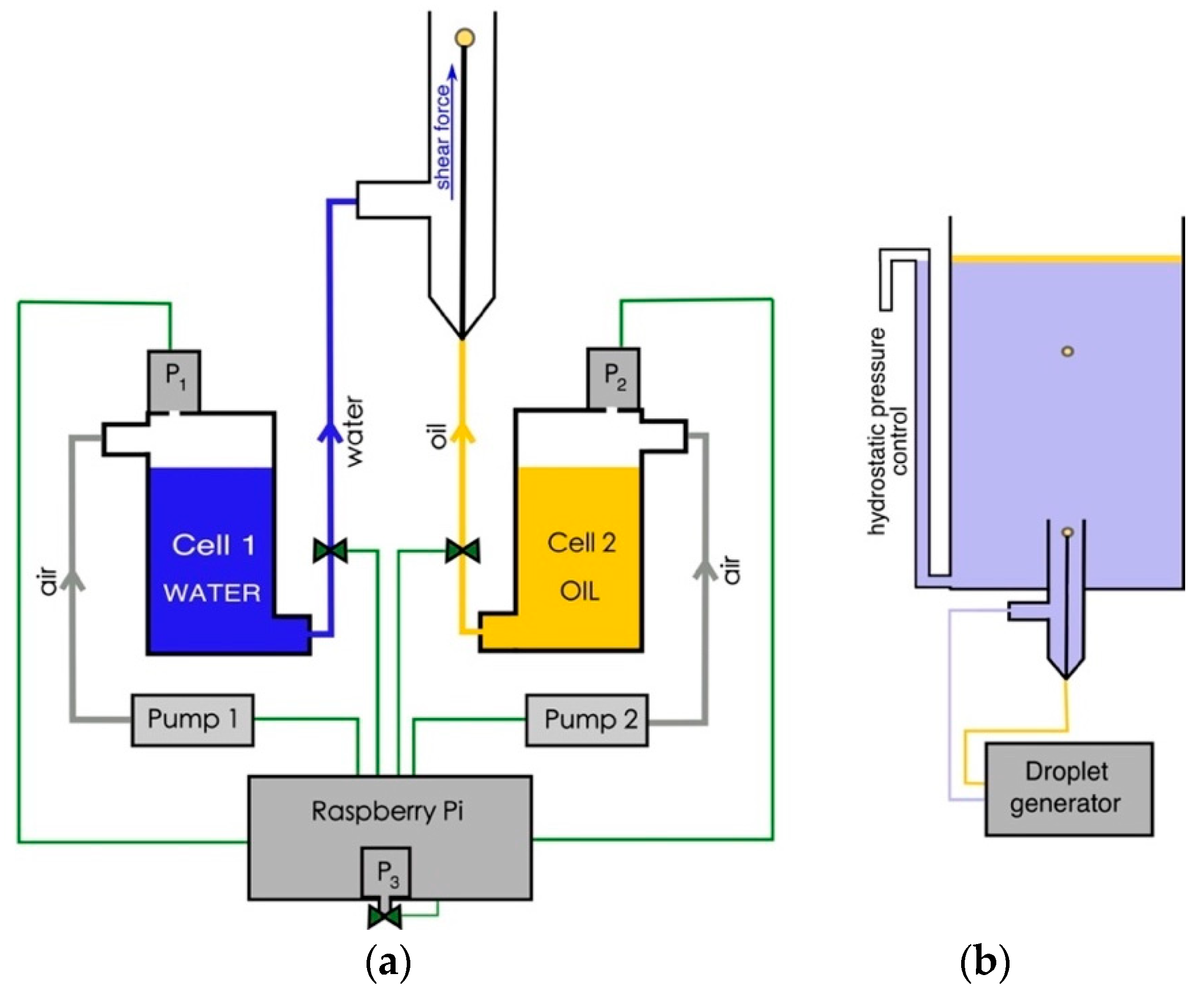
All the experiments were carried out using a single-droplet generator, which was fully developed and built in our laboratory. The experiments were aimed to test the generator precision and potential in a single droplet generation of desired size. The schematic illustration of the main parts of the device is presented in
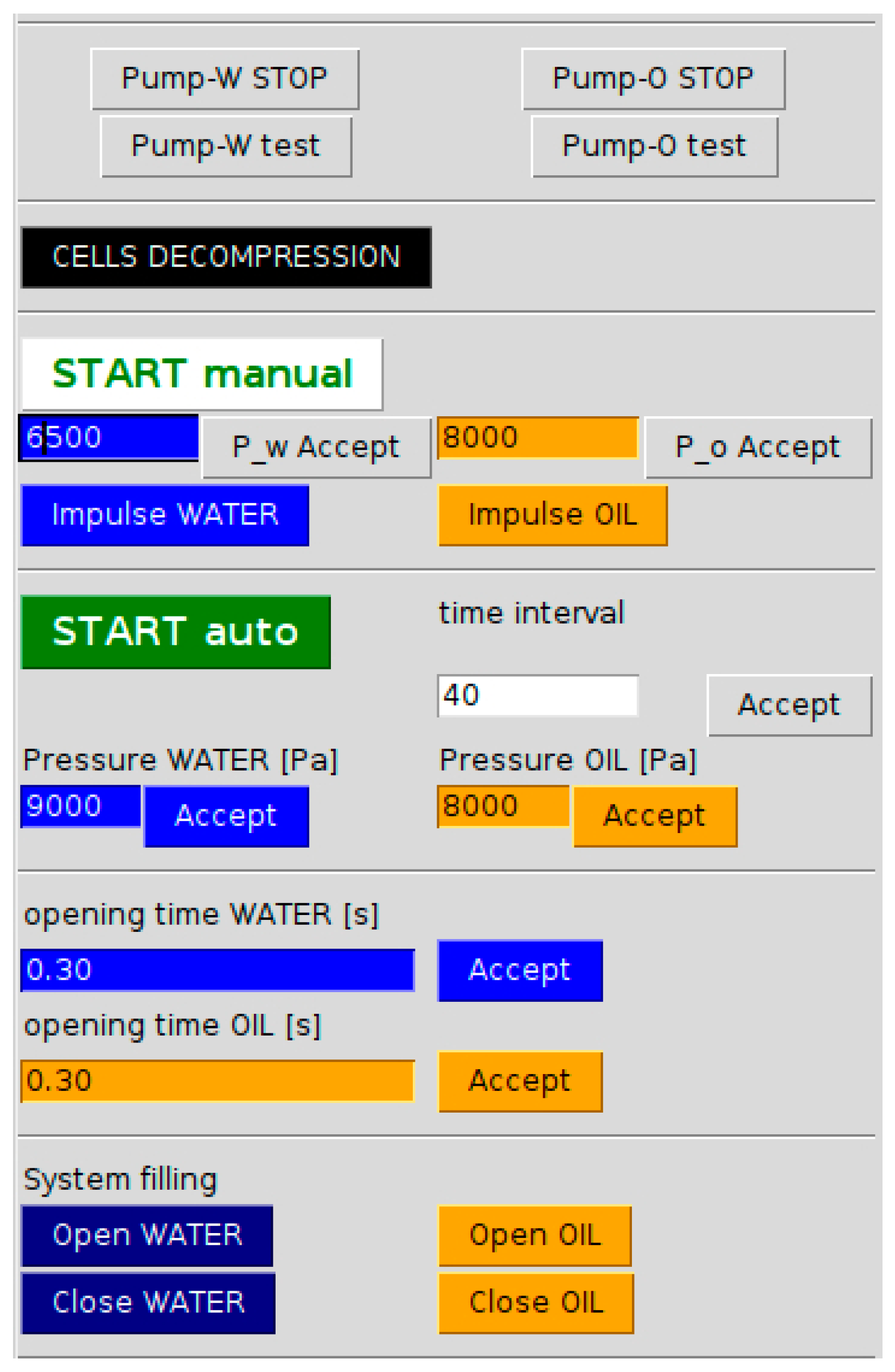
Figure 1a. It consists of (i) two identical, programmable, low pressure peristaltic pumps (DC 12 V, flow rate 20-60 mL/min with silicone tubes of 2 mm inner diameter) connected to (ii) two glass pressure cells (height 70 mm and width 35 mm, round cross-section) and controlled via dual stepper motor driver (L298N, Induino ST1112); (iii) three pressure sensors (GY-68 BMP180, I2C); (iv) two polytetrafluoroethylene (PTFE) two-way valves, automatized using the servomechanism (Giant Servo HD-1235MG); (v) two pressure stabilizers; (vi) glass tube with side-tube (cross-Section 8 mm,) and thin steel needle (outer diameter 0.3 mm) sealed concentrically, referred further in the text as generation nozzle, as well as (vii) Raspberry Pi 3 microcomputer for control and synchronization of all electronic parts of the generator by means of developed software with user-friendly GUI (graphical user interface), presented in more detail in
Appendix A.
The following procedure was applied to generate a single oil droplet in water. First, the two-way valves of the pressure cells (Cell 1 and Cell 2) were closed and the cells were filled with corresponding, immiscible liquids directly from the beakers. Next, the cells were pressurized independently by two peristaltic pumps according to the precisely adjusted (using software) pressure values (P1 and P2). These pressures were in fact overpressures, normalized to zero at the beginning of the procedure, according to the ambient pressure measured by the third, independent sensor (P3). Tubes used for cells pressurization were made of silicone (inner diameter 2 mm). Chemically resistant PEEK (polyether ether ketone) tubes (inner diameter 0.7 mm) were used for oil transport from the cell, through the PTFE valves to the generation nozzle. In the case of water, a PTFE tube with inner diameter 2 mm was applied. When the desired pressure values were reached independently in each cell, two-way valves of the both cells were open to fill the tubes with respective liquids, which were pumped thanks to the overpressure inside the cells. Correct, adjusted overpressure in the cells were continuously controlled and supplied, if necessary, by the peristaltic pumps. The procedure of system filling was monitored visually by observation of the air bubbles appearing inside the generation nozzle at the needle tip and continued till all air was pushed out and the first oil droplet appeared and detached from the needle tip, which indicated that the needle is filled with oil and both PTFE valves can be closed. To generate the single droplet the PTFE valve of the oil cell (Cell 2) was opened and then immediately closed. Time between valve opening and closure could be precisely adjusted. This was a very important parameter, determining the size of the droplet formed at the needle tip. After formation under the impulse of the oil phase flow of adjusted amplitude (pressure), the droplet was immobilized at the needle, as capillary force related to the needle/droplet attachment area exceeded buoyancy. To detach the droplet, water co-flow was applied. The droplet detachment was forced using water flow impulse generated from the water cell (Cell 1) to the side tube of generation nozzle. Magnitude of this impulse (and hence water flow rate and, consequently, shear force exerted at the droplet surface) depended on P1 value. In practice, the water impulse was adjusted carefully to be as small as possible, to avoid significant droplet deformation during too violent forced detachment. After each oil or water impulse, the peristaltic pumps supplied the pressure to the desired (adjusted) level. The pressure inside the cell could be freely modified, either up or down, by peristaltic pumps operating in pumping (forward pump rotation) or withdrawing (backward pump rotation) modes.
To measure the droplet size and rising velocity, the generation nozzle was connected to the square glass column, according to the scheme presented in the
Figure 1b. Each water impulse generated to detach a droplet caused an increase in the water level inside the liquid column, which modified the hydrostatic pressure. Therefore, a small side silicone tube was connected to the bottom of the column to keep the water level constant and controllable. Pictures of a single droplet detaching from the needle tip and rising in water were recorded using high-speed camera (with relatively low frequency applied, equal to 100 Hz). To extract the droplet motion parameters (rising velocity, shape deformation) and its size, well-known procedures, described in details elsewhere [
20], were utilized. In this procedure the Python (programing language) script for automatic and fast image analysis was used. Terminal velocity was calculated as an average from five independent runs (five different droplets) for data collected at the distance when a droplet velocity was constant. Equivalent droplet diameter was calculated assuming an ellipsoidal droplet shape, as:
where
dh and
dv is horizontal and vertical diameter.
2.2. Materials
Dodecane oil was used for testing the generator potential and precision. We used contaminated dodecane available in our laboratory, with water/oil interfacial tension equal to 33 mN/m. We decided to do so, because, for preliminary tests of the generator capability, the system purity was an insignificant parameter. Milli-Q water with surface tension 72.4 mN/m was used in all the experiments, which were carried out at a room temperature equal to 22 ± 1 °C.
3. Results and Discussion
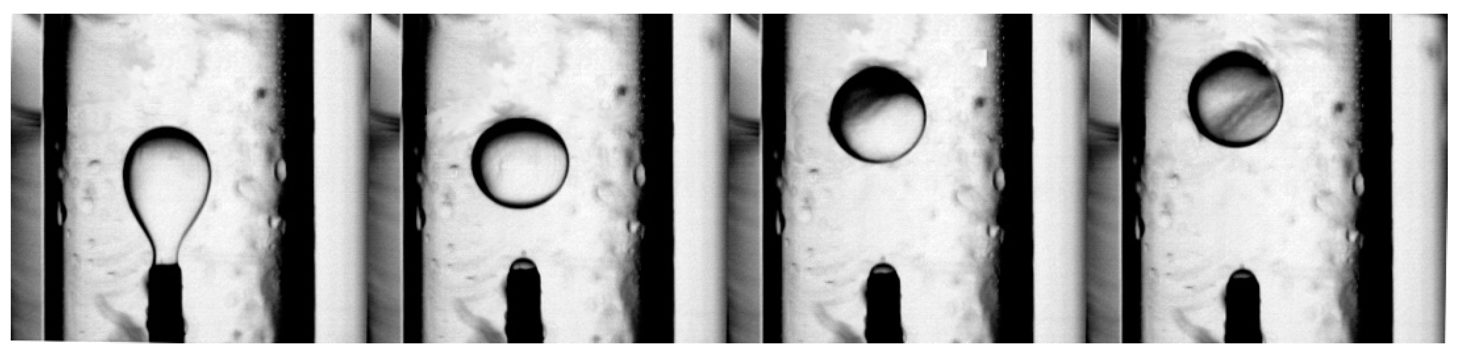
A sequence of photos showing moment of a single droplet detachment from the needle tip are presented in
Figure 2. The first photo presents the elongated droplet shape, which is a consequence of the shear flow of water (generated impulse) parallel to the needle. The detached droplet starts to rise as a result of buoyancy. Please note that due to the carefully adjusted magnitude of the water shearing impulse, the droplet shape is only slightly disturbed, which is positive feature of the method, especially when the influence of the adsorption layer’s existence at the oil/water interface is investigated. It is worth mentioning here that such methodology of single droplet generation allows precise and free control over time of a droplet residue at the needle tip. Therefore, this method is a great tool for investigation of influence of time available for adsorption of surface-active substances at liquid/liquid interface on droplet motion parameters, as well as stability of single thin films formed, when the oil droplet reaches the upper liquid surface (liquid/air, liquid/liquid or compound interfaces). In addition, this method can be easily adjusted to produce water drops falling in oil as continuous phase for study inversed emulsion systems.
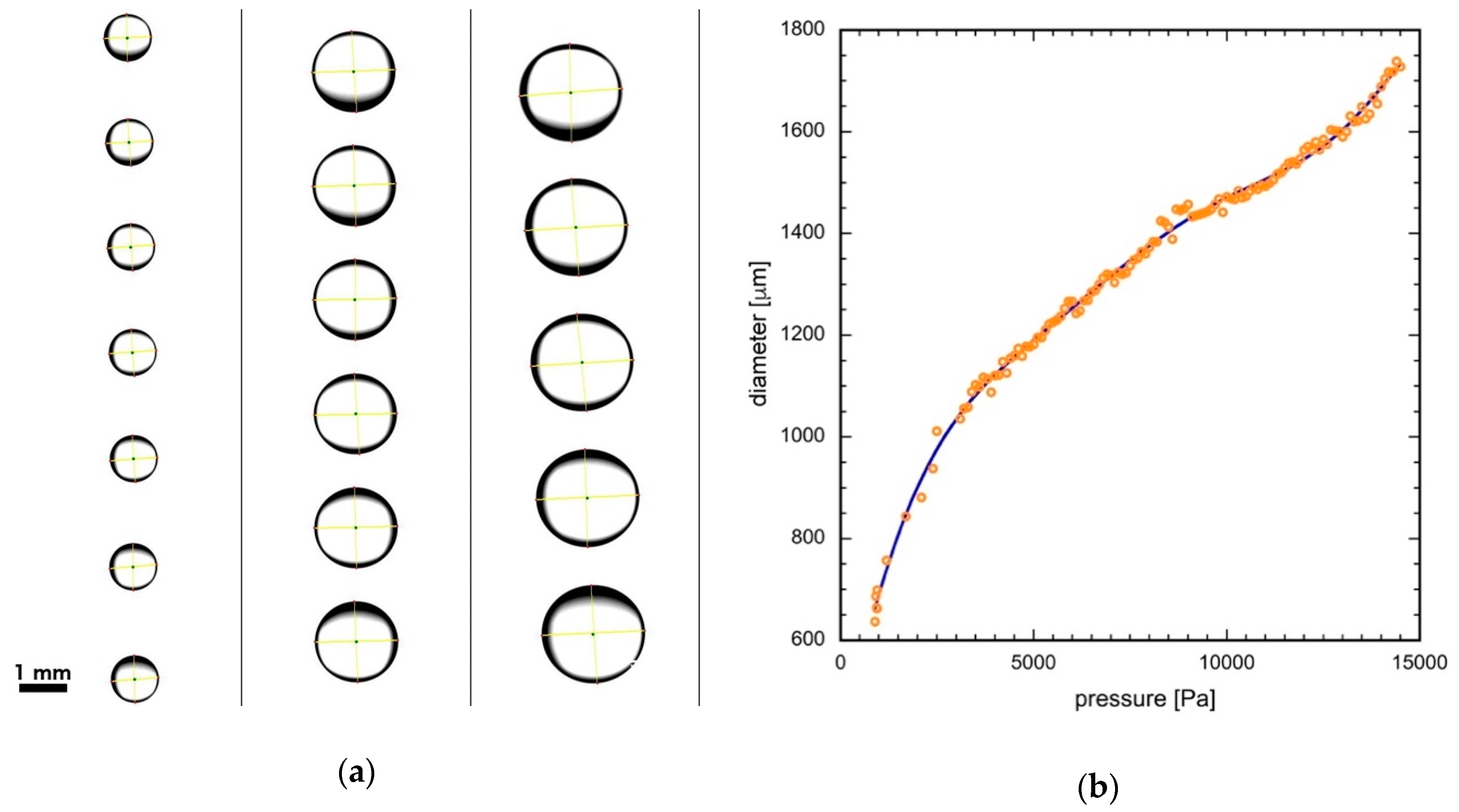
Figure 3a presents photos of single droplets of various sizes, after automatic image analysis was applied. Each column presents different subsequent droplets positions. As seen, elaborated software determines the position of the geometric center of the droplet as well as
dh and
dv values, for calculations of a shape deformation ratio (
dh\
dv) and d values.
The pressure characteristics of the generator under experimental conditions, i.e., dependence of droplet diameter as a function of overpressure inside the oil cell (Cell 2), are presented in
Figure 3b. The points represent experimentally obtained data, while the solid line is a fitted polynomial. Using fitted equation, all parameters of the generator can be easily adjusted to produce a droplet of the desired size. No error bars for diameter values are shown in the Figure for clarity. In practice, the relative standard deviation (RSD) was less than 4%.
It has to be underlined that, obviously, the pressure characteristics presented in
Figure 3b are valid only under certain experimental conditions, and will be different for different physical parameters of the dispersed (oil) phase, various values of interfacial tension and hydrostatic pressures (height of the liquid column). Such characteristics however, can be easily determined and catalogue for different substances as well as experimental set-up geometry, and used as a guideline (kind of “calibration curves”) during experiments performed under reproduced conditions. This is a big advantage of the method, allowing a simple way of repeating the experiments using “calibrated” systems, without blind tests.
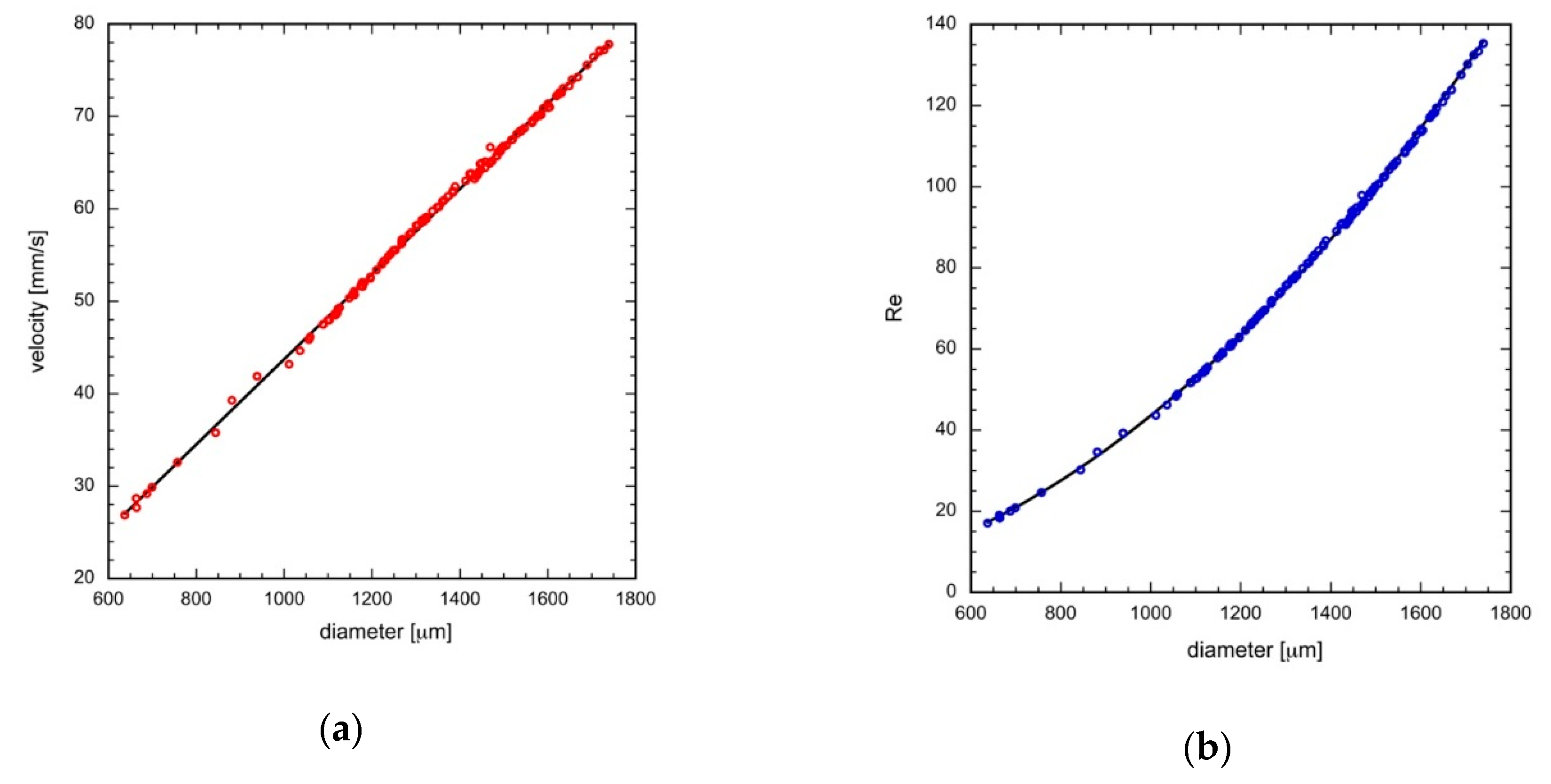
Figure 4 presents terminal velocities of a single droplet (
Figure 4a) and corresponding Reynolds numbers (
Figure 4b) as a function of the droplet size. Terminal velocity of every object rising (or falling) in a liquid phase is reached when the buoyant force and drag force of a continuous medium are equal. Buoyant (
FB) and drag (
FD) forces can be expressed as:
where
Vb is an object volume, Δ
ρ is difference between density of dispersed (
ρd) and continuous (
ρc) phases,
g is gravitational acceleration, A is object projected area,
CD is drag coefficient and
u is terminal velocity. In our case, due to the fact that the oil was contaminated with surface-active substances, rising droplet surface should be immobile (as a result of motion induced surface tension gradients) and can be treated as a surface of a rigid sphere. Drag coefficient of a rigid sphere can be calculated from the empirical correlation given by Schiller–Naumann [
21]:
where
Re is the Reynolds number, which, for the droplet of diameter
d rising in continuous medium of viscosity
μc can be expressed as:
After rearrangement of Equations (1)–(4), assuming that the
Vb is equal to 1/6πd
3 and A is equal to 1/4πd
2, the theoretical droplet terminal velocity can be calculated as:
Theoretical dependences calculated from Equations (3)–(5), according to the physical parameters of dispersed (oil) and continuous (water) phases given in
Table 1, are shown in the
Figure 4, as solid lines. As seen, very good agreement between experimental data and theoretical predictions was obtained. It indicates that indeed, the droplet surface was fully no-slip (immobilized). Moreover, the presented results confirm the reliability of the droplet generation method and generator itself. It is seen that using our automatic generator quite wide range of droplet size can be obtained. In practice, by using a steel needle of an outer diameter of 0.3 mm, droplets with size ranging between 600 μm to 3.5 mm can be easily produced. In addition, droplet size can be changed smoothly and continuously. The RSD of determined velocity values shown in
Figure 4a was less than 5%.
As was mentioned above, the time of the opening of the PTFE valve of oil cell (Cell 2) could be freely adjusted. Therefore, the size of the formed droplet could be controlled not only via control of the overpressure in the cell, but it also depended on the valve opening time, when the overpressure was constant.
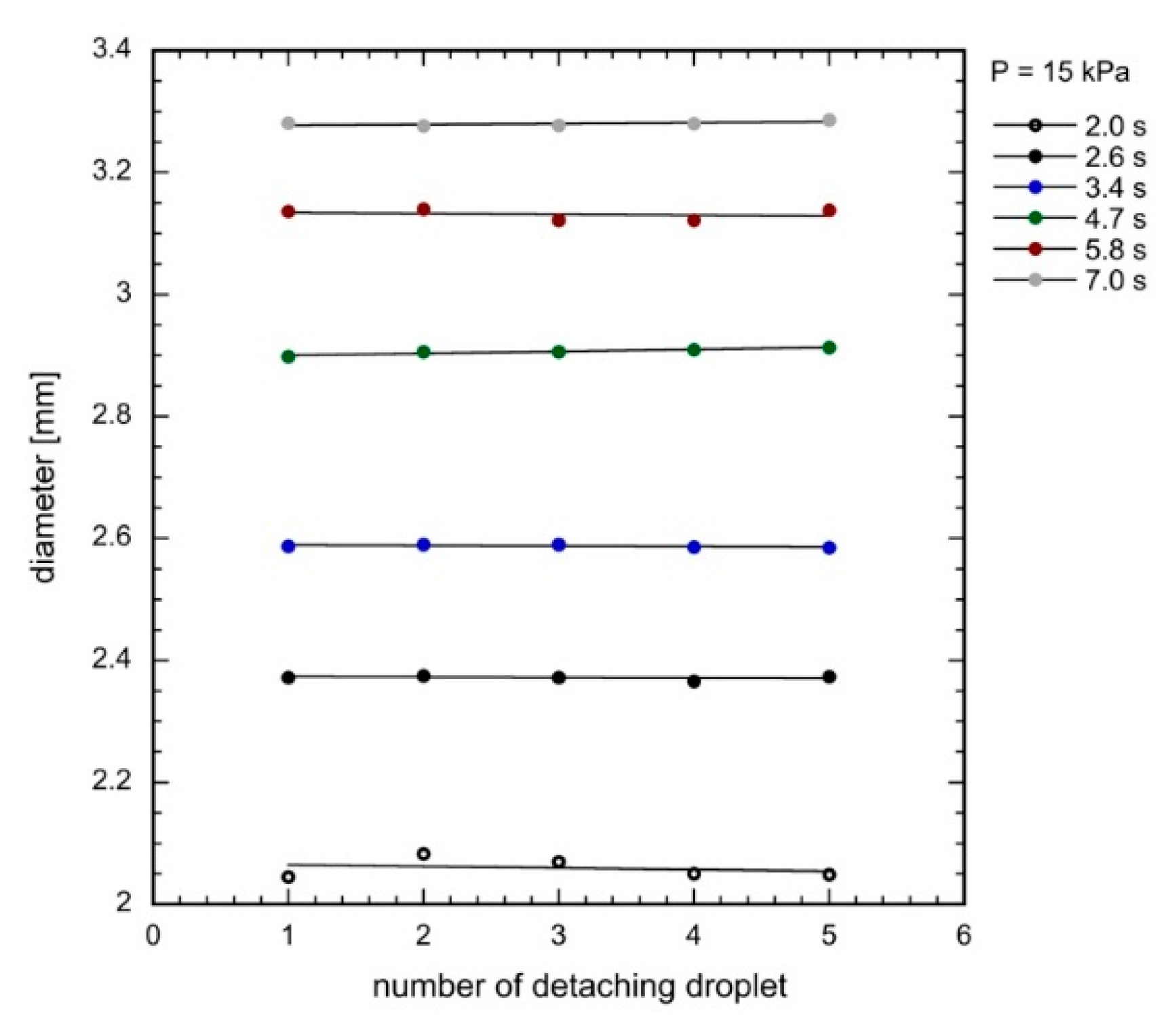
Figure 5 presents measured droplet diameter values for five independent runs (detached droplet) for constant oil cell overpressure (15 kPa) and six different values of time of the oil cell (Cell 2) PTFE valve opening. As seen, indeed this method of droplet size control works very well. In practice, the minimum time of open/close cycle of the valves was equal to 0.3 s, so much smaller droplet diameters could be obtained using this approach. In addition, from the results presented in
Figure 5, the precision of our generator can be judged. Values of the droplet diameters formed in five independent runs (under five subsequent oil and water impulses) are practically identical, which indicates that the developed generator is able to produce monodisperse droplets of repeatable sizes. This is an extremely important feature in respect to the fundamental studies on emulsion stability, single emulsion films drainage and coalescence phenomenon, where liquid film size is of crucial importance.
4. Conclusions
We have developed quite a simple, fully automatized single droplet generator, which can be an alternative for more expensive and complicated microfluidic devices. The simple generation nozzle connected to the pressure cells and cheap peristaltic pumps, synchronized via developed software with simple GUI allows precise control over the single droplet diameter and detachment frequency. The generator allows the formation of droplets on demand, in quite a wide range of diameters with very good precision and accuracy without need of orifice diameter replacements. Free control over time available for adsorption of surface active-substances over the immobilized droplet (degree of adsorption coverage at liquid/liquid interface), before its detachment from the orifice, is a great advantage of the developed device. Obviously, any kind of liquids can be used as oil and aqueous phases, i.e., various kind of oils and water solutions of various substances, including surfactants can be examined. The geometry of the experimental set-up can be easily modified allowing investigations on the dynamics of falling water (or water solution) droplets in the oil phase, mimicking dynamic phenomena in the inversed emulsion systems.


