Abstract
Today, the drilling operators use the Colloidal Gas Aphron (CGA) fluids as a part of drilling fluids in their operations to reduce formation damages in low-pressure, mature or depleted reservoirs. In this paper, a Taguchi design of experiment (DOE) has been designed to analyse the effect of salinity, polymer and surfactant types and concentration on the stability of CGA fluids. Poly Anionic Cellulose (PacR) and Xanthan Gum (XG) polymers are employed as viscosifier; Hexadecyl Trimethyl Ammonium Bromide (HTAB) and Sodium Dodecyl Benzene Sulphonate (SDBS) have been also utilized as aphronizer. Moreover, bubble size distributions, rheological and filtration properties of aphronized fluids are investigated. According to the results, the polymer type has the highest effect, whereas the surfactant type has the lowest effect on the stability of CGA drilling fluid. It was also observed that increasing salinity in CGA fluid reduces the stability. Finally, it should be noted that the micro-bubbles generated with HTAB surfactant in an electrolyte system, are more stable than SDBS surfactant.
1. Introduction
Aphrons that are known as colloidal dispersed micro-bubbles (with size distribution between 10–100 microns), usually consist of a spherical core with an internal phase covered by a thin shell. If the core has a gas phase, the considered structure is known as colloidal gas aphron. In order to use aphrons as drilling fluids, they require a certain degree of stability. For this reason, the Aphron shell must have enough thickness (between 4 to 10 microns), otherwise it cannot bear the pressure, also it is better that protective layer has lower viscosity. Aphron stability is affected by the mass transfer rate between the viscous water shell and the bulk phase. This phenomenon is described as Marangoni effect (mass transfer along an interface between two fluids due to a gradient of the surface tension). As a result of this effect, water (or Aphron’s core gas) molecules tend to diffuse out from the Aphron shell into bulk liquid, which is lead to destabilize the Aphron [1]. Generally, Aphron consists of gas, water, certain polymers and surfactants to make a micro-bubble suspension. The polymer is used to increase the viscosity of water and a surfactant is required to generate micro-bubbles by reducing surface tension of the base fluid. Variety of scientists have contributed to a deeper insight into the performance of Aphrons and the controlling parameters. Save and Pangarkar [2] studied the effect of viscosity on CGA based fluids stability half-time and drain rate (the rate of drained liquid from CGA dispersion). Due to the difference between density values of the bubbles and liquid, the bubbles tend to move upward and the liquid is drained downward. The drain rate refers to the rate of liquid, which is separated from the Aphron fluid. They observed that any increase in viscosity increases half-time of the CGA fluid sample due to drain rate reduction in presence of increased viscosity. Jauregi and co-workers [3] studied the CGA stability in terms of the surfactant concentration. They concluded that, as surfactant concentration increases, CGA stability increases. Brookey [4] used a Xanthan gum (XG) biopolymer as the best stabilizer of CGAs and enhancer of the low shear rate viscosity (LSRV) that has a positive impact on wellbore cleaning, cuttings suspension and invasion control. An excellent drilling cutting suspension reduces the wellbore erosion especially in highly deviated and horizontal wells; this excellent cutting suspension is achievable by elevating low shear rate viscosity value. Ramirez et al. [5] proposed non-ionic polymers to increase viscosity at low shear rates. Growcock [6] stated that clay/polymer blends can be used as viscosifier. Bjorndalen and Kuru [7] proposed the XG biopolymer to stabilize aphron and also mentioned that viscosity has the most impact on Aphrons stability. Keshavarzi et al. [8] used three surfactants SDS, Triton X-100 and CAPB for investigation the formation and stability of CGAs. Their study reported that, CGAs made by SDS and CAPB surfactants have significant stabilities in contrast to the poor stability of Triton X-100. Huang et al. [9] investigated the fluid loss of surfactant viscoelastic fluids in different temperatures and permeabilities. Their results revealed that a filter cake was created on the porous media that caused the reduction of fluid loss. Arabloo et al. [10] studied CGA fluid properties by using a mixture of surfactant and xanthan gum biopolymer. Their study reported that, as the polymer and surfactant concentration increases, the yield point, plastic viscosity (which will be named in this paper as viscosity) and apparent viscosity of CGA based drilling fluids increase. Tabzar et al. [11] investigated various bio-polymers including Carboxy Methyl Cellulose (CMC), Starch and Xanthan Gum and two types of surfactant, namely Cetyl Trimethyl Ammonium Bromide (CTAB) and Sodium Dodecyl Sulphate (SDS) to make aqueous CGA drilling fluids. The outputs of their research showed that a mixture of XG and SDS has a great performance in decreasing filtration loss and improvement of stability of CGAs. All the mentioned works have been performed on the water based CGAs, which is not proposed to be used in high temperature and shale formations. In such formations the oil based Aphrons will have better efficiency. Unfortunately, there is a lack of study on oil based CGAs in literature. Only two works of Growcock et al. [12] and Alizadeh and Khamehchi [13] are available in literature related to oil based CGAs. Growcock et al. [12] introduced the oil based Aphron fluids and investigated its application in drilling fluids. Alizadeh and Khamehchi [13] experimentally investigate the oil based CGAs stability. They used different kinds of vegetable oil in their study due to environmental consideration. It should be mentioned that, the oil based Aphron is suitable for shale formation drilling because it does not cause shale instability; also, oil-based fluids are good lubricants, which reduces the drilling torque.
Another important parameter, which controls the behaviour of CGA based drilling fluids, is the bubble size and size distribution of CGAs. Parthasarathy et al. [14] estimated the average bubble diameter of CGAs based on Kolmogorov’s theory. They planned to experimentally study the small bubbles created by gas dispersion mechanism in presence of a ventilated cavity attached to a cylindrical vessel. Therefore, they needed to predict the size of bubble before the experiment for optimizing the experimental parameters and count, for reducing cost and time. In this state, they used Kolmogorov’s theory of turbulence to predict the size of bubbles. As the result of the study, the predicted diameters generally were in 20% of their measurements. Roy and co-workers [15] applied a Particle Size Analyser to estimate the bubble size distribution of CGAs. Their instrument projected a laser beam through a transparent cell containing a stream of moving particles suspended in the liquid. Majority of CGAs produced from HTAB had a mean diameter of 125 microns and the CGA bubbles from the SDBS surfactant had a mean diameter of 88 microns. Dai et al. [16] employed optical microscopy and image analysis to determine the size of the generated CGAs. The mean diameter of 55.02 microns was reported in their study. Also, they investigated the effect of PH on the stabilization and size of CGAs. Arabloo et al. [10] employed a charged coupled device camera and a light microscope to investigate the size distribution of CGAs of different aphronized drilling fluids. Alizadeh and Khamehchi [17,18,19,20,21,22,23,24] proposed a new and novel diffusion model for CGA fluids including the mass transfer, which is described as diffusional phenomena in the presence of convective motion. In this model the mass transfer resistance for all phases and interfaces of a bubble was taken into account. Result of their study illustrated that the bubble sizes decrease and stability increases until a threshold value in case of increasing surfactant concentration in the base fluid. This threshold value varies with base fluid type, pressure, temperature and surfactant type. In their researches, a first-order differential model was used for liquid drainage modelling from the dispersion, while bubble size distribution was predicted using a population balance model. Moreover, the result shows that increasing the surfactant concentration usually increases the stability of the produced micro bubble fluid, due to the increase of viscosity, yield point, apparent viscosity and gel strength. As polymer and surfactants concentration increase, the viscosity of the base fluid and the bubble population increases respectively, which will increase the overall viscosity of the CGA drilling fluid.
In the current study, the significant focus is to investigate the effect of salinity, type of polymer and surfactant and also their concentrations on stability, size distribution, rheological properties and filtration loss of water based CGA drilling fluid. Taguchi design of the experiment is designed for understanding the effect of mentioned parameters on the stability of the CGA fluids. Section 2 will describe the methodology. Then the results will be presented and discussed in Section 3. Finally, we will end this research with main concluding remarks.
2. Methodology
2.1. Materials
In this work, water was utilized as the based fluid of micro-bubble drilling fluid. Poly Anionic Cellulose (PacR) polymer and Xanthan gum (XG) were employed as stabilizer and viscosifier. Hexadecyl Trimethyl Ammonium Bromide (HTAB, CMC 0.9 mM) as a cationic surfactant and Sodium Dodecyl Benzene Sulphonate (SDBS, CMC 1.5 mM) as anionic surfactants were utilized as aphronizers. In order to adjust salinity of aphron, NaCl was utilized.
2.2. Tauchig Approach for Design of Experiment
The Taguchi approach is known as one of the popular designs of experiments. This approach decreases the variations during the experiment process to reach high-quality results in low cost experiments in minimum time. Genichi Taguchi proposed his approach to design experiments based on variance and average of process performance attribution. This approach utilizes orthogonal arrays to determine the influence of different parameters on the process and to identify the levels which will be changed. Taguchi approach uses pair combinations of possible test to calculate the most effective factors on the number and quality of experiments. This approach leads to an affordable and time-benefit design of experiments. When the number of variable parameters is intermediate (3 to 50), the best performance of Taguchi approach is obtained.
In this study, Taguchi design of experiments (DOE) was used to minimize the number of experiments and determine the number of trial experiments, which is required for process analysis. Table 1 shows the factors and levels of the parameters used in this investigation. The considered L36 array for DOE is also shown in Table 2.

Table 1.
Parameters and their different levels.
Table 2.
L36 Taguchi orthogonal array design.
2.3. Preparation of Fluids
In order to prepare the drilling fluid, the polymer was initially mixed in 350 cc water (1 laboratory barrel). The polymer-water mixture was agitated for 20 min at a speed of 10,000 Rate per Minute (RPM) by a Hamilton Beach mixer. To aphronize this base fluid, surfactant was added to the system; afterward, it was mixed for 10 min at the same speed. The Aphron fluid was then homogenized for 2 min at a speed of 8000 RPM. For fluids which contain NaCl in their composition, before adding polymer and surfactant to the fluid, the salt solution with considered concentration, was prepared by mixing NaCl in 350 cc water, before adding polymer and surfactant to the fluid.
2.4. Stability of CGAs
To measure the stability, 100 cc of CGAs was filled in a 100 cc cylinder. The one-tenth drained life “T0.1” (the time elapsed when the drained liquid from CGA reaches ten percentage of its final height) was measured as an index for stability of CGA. Time half-life, “T0.5” is conventionally used for evaluation of aphron stability. But in this study, “T0.1” was considered for evaluating the stability of CGA, because it is more suitable for characterizing the CGA drilling fluid and predicts the stability more accurately than the lengthy half-life time [25].
2.5. Visualization of CGAs
A Dino-lite digital capture camera microscope was used in this experiment for imaging micro-bubbles of CGAs, which is shown in Figure 1. After preparing Aphron drilling fluid, a sample of fluid was immediately imaged and both size distribution and bubble sizes of micro-bubbles were determined by an image processing program.
Figure 1.
Schematic view of Dino-Lite Pro Microscope.
2.6. Rheological Characterization and Filtration Reduction Evaluation of the Fluids
A Fann 35 viscometer was used to measure the apparent viscosity, viscosity, yield point and gel strength (10 s and 10 min) of aphron drilling fluid. Filtration loss of fluid was also measured by a 100 psi API filter press. The amount of filtrate in millilitre was measured during a 30 min time interval.
3. Results and Discussion
3.1. Design of Experiment Analyzes
In general, the experimental analysis is time-consuming and expensive. Accordingly, as previously mentioned, L36 array Taguchi design of experiments (DOE) was adopted in this study to reduce the number of trials. In this context, 36 samples were generated based on DOE and stability, density (gr/cc) and initial volumetric fraction of micro-bubbles of the CGA drilling fluids were measured immediately after CGAs generation (Table 3). To analyse the data, stability was considered as the performance parameter (as output), then the data was plotted against all levels of all design parameters. In Taguchi’s design method, the design parameters (i.e., factors that can be controlled by designers) and noise factors (i.e., factors that cannot be controlled by designers, such as environmental factors) are considered influential on the product quality. The Signal to Noise ratio (S/N) depends on the quality characteristics of the product/process to be optimized. Usually, there are three categories of the performance characteristics in the analysis of the S/N ratio; that is, the lower-the-better, the higher-the-better and the nominal-the-better. In the present study, the stability factor is the-higher-the-better performance characteristics. Once all of the S/N ratios have been computed for each run of an experiment, Taguchi advocates a graphical approach to analyse the data. In the graphical approach, the S/N ratios and average responses are plotted for each factor against each of its levels (Figure 2).
Table 3.
Experimental Results.
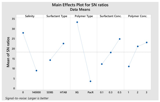
Figure 2.
S/N ratios and average responses for stability.
3.2. Stability of CGAs
The resistance of fluid against the degree of dispersion, liquid content and bubble size alteration can be considered as the main index of CGA based drilling fluids stability [11]. According to DOE results, as shown in Figure 2 and Table 4, polymer type significantly affected the stability values and surfactant type has the lowest effect on stability. PacR is a combined filtration controller and viscosifier for water-based drilling fluids systems, the best for low solid muds and acts as a high yield viscosifier. As seen in Table 3, in early times, by using PacR in CGA composition, the micro-bubbles of CGA are so unstable and the liquid phase of the fluid drained rapidly just after Aphron generation. The S/N ratio response in Taguchi’s DOE also shows this result. On this basis, that polymer type in the second level (PacR polymer) has the least S/N ratio, 3.56. When the XG polymer was used, the stability increased and micro-bubbles became stable and dispersed in the fluid. The S/N ratio response of this parameter is 33.26 which is the maximum value. XG shows a better performance in increasing fluid stability compared to PacR; XG has been used as Aphron stabilizer in many research and outperformance has been also reported [4,26,27].
Table 4.
Response Table for S/N Ratios (Larger is better).
The effect of surfactant type on stability is lower than other parameters. The difference between S/N ratio of SDBS and HTAB surfactants is 8.37, which illustrates that both surfactants have a relatively close effect on the micro-bubble stability of CGAs fluid.
Polymer and surfactant concentration have the same effect on stability. According to Figure 2, while the polymer concentration increases, the S/N ratio also increases which is equal to increase of stability. As the surfactant concentration increases, the number of bubbles is increased. Furthermore, as fluid viscosity increases, the bubbles maintenance and stability increase; because higher viscosity causes a delay in liquid hydrodynamic flow out of bubbles [28].
Increasing salt (NaCl) concentration from 0 to 140,000 mg/L decreased S/N ratio from 27.89 to 8.94. Therefore, we can say that, the salt concentration is the second parameter which has the most effect on stability. According to Table 3, in case of using HTAB and XG in CGAs, electrolyte reduces the stability but this reduction is very low. For HTAB and XG mixtures, increasing salt concentration reduces the “T0.1” from 360 to 320 min but this reduction for SDBS and XG mixture is from 843 to 45 min. In the presence of salt, the electrical double layers of Aphron shell are compressed and this lead to decrease liquid shell thickness and hence decrease the stability of Aphron [2].
3.3. Visualization and size Distribution of the CGAs
CGA drilling fluid samples were imaged immediately after generation by using Dino-lite digital capture camera microscope. Figure 3 shows a typical microscopic photo of CGA drilling fluid and the micro-bubbles detected by image processing. Photo of CGA fluid was analysed by an image processing code detecting about 75% of the bubbles present on a microscopic image. In course of image processing bubble size distribution and average bubble diameter are calculated (Table 5).
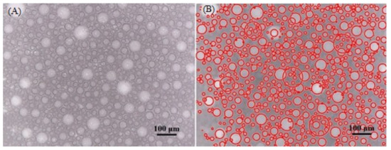
Figure 3.
Typical microscopic photo of CGA drilling fluid (A) and its detected bubbles by image processing (B).
Table 5.
Average bubble size of CGA drilling fluid.
The results of bubble size distribution are shown in Figure 4, Figure 5, Figure 6, Figure 7, Figure 8 and Figure 9. The effect of salinity, polymer type and surfactant type on size distribution are depicted in these Figures. Figure 4 and Figure 5 represent the effect of salinity on the size distribution of XG and PacR polymer in the presence of SDBS surfactant. Increasing salt concentrations decreases bubble size of aphrons while this reduction for XG polymer is more than PacR. The average bubble size decreased from 55.6 and 43.7 microns to 41.5 and 36 microns for XG and PacR polymer, respectively.
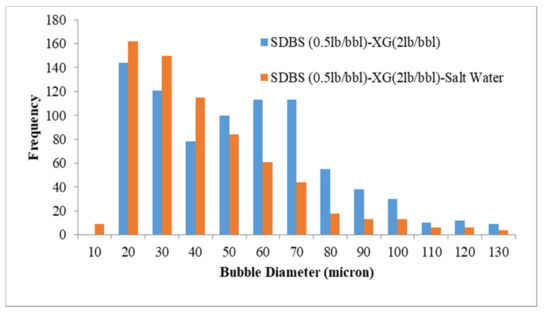
Figure 4.
Effect of salinity on bubble size distribution (CGA prepared by SDBS and XG).
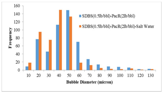
Figure 5.
Effect of salinity on bubble size distribution (CGA prepared by SDBS and PacR).
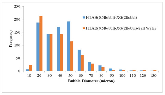
Figure 6.
Effect of salinity on bubble size distribution (CGA prepared by HTAB and XG).
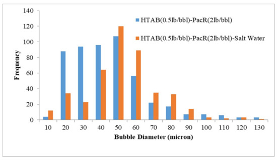
Figure 7.
Effect of salinity on bubble size distribution (CGA prepared by HTAB and PacR).
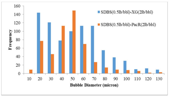
Figure 8.
Effect of polymer type on size distribution by using SDBS surfactant.
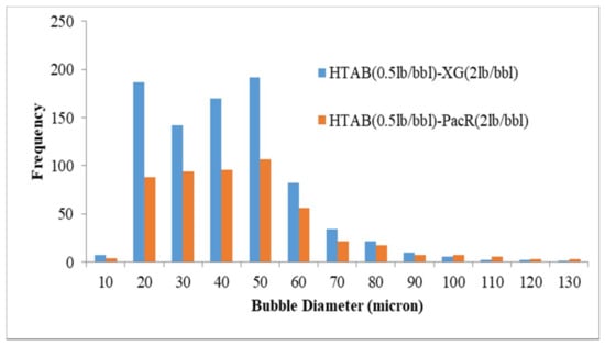
Figure 9.
Effect of polymer type on size distribution by using HTAB surfactant.
According to the results reported in Figure 6, adding salt to HTAB-XG based CGA fluid decreased bubble size of Aphron but for HTAB-PacR based CGA fluid increasing salt concentration increased the size of bubbles (Figure 7). The average bubble size for these two types of fluid has not changed significantly with increasing salt concentration (1.8 microns reduction of average bubble sizes for XG and 2 microns increment for PacR).
Figure 8 illustrates the effect of polymer type on the bubble size distribution of CGA drilling fluid prepared by SDBS. By using XG as viscosifier, most of the bubbles are between 20 to 100 microns with average bubble size of 55.6 microns and in the presence of PacR polymer most of the bubbles are limited to the range of 20 to 70 microns and the average bubbles sizes for this polymer is 43.7 microns. In case of using the HTAB surfactant as an aphronizer for both polymers, the Aphron bubble sizes arranged between 20 to 70 microns (Figure 9) with the average bubble size of 37.4 and 46.7 microns for XG and PacR, respectively. It should be noted that by using PacR as viscosifier in the composition of CGA drilling fluid, the number of bubbles was lower than XG polymer and the composition of HTAB and PacR had the lowest number of bubbles.
As discussed before, utilization of PacR as aphron stabilizer did not lead to satisfactory results, also the drainage rate of the fluid was so fast. The number of bubbles generated when using this type of polymer is also lower than XG, so it can be concluded that PacR is not a good polymer for CGA drilling fluids but it should be noted that this result is true when using SDBS and HTAB surfactant.
3.4. Rheological Properties and Filtration of CGAs
Apparent viscosity, yield strength, viscosity and gel strength (initial and 10 min) of the CGA drilling fluids were obtained using Fann 35 viscometer. In this section, the rheological data for all experiments are not reported because some of the fluids do not have the necessary stability for rheology measurements. Therefore 10 fluid samples with the desired stability were chosen for obtaining rheological properties. Table 6 shows the rheological properties of these 10 samples of CGA drilling fluids.
Table 6.
Rheological properties of CGA drilling fluids.
According to the results reported in Table 6, it is obvious that increasing surfactants and the XG concentration tend to increase the viscosity, yield point, apparent viscosity and gel strength. As XG and surfactants (SDBS and HTAB) concentration increases, the viscosity of the base fluid and the bubble population also increase respectively, which will increase the overall viscosity of CGA drilling fluid. The viscosity for SDBS based CGA is lower than HTAB in the same concentration of surfactant and polymer.
Viscosity is usually described as that part of the resistance that acts against the flow caused by mechanical friction, so for HTAB based CGA, which has more bubbles present in the fluid, the mechanical friction in the system increases and ultimately leads to an increase in viscosity.
Yield point, another component of resistance to flow in a drilling fluid, is the magnitude of the electrochemical or attractive forces in a fluid. Yield point for SDBS based CGA is higher than HTAB based CGA in the same concentration of surfactant and polymer, so it can be concluded that the electrochemical forces in SDBS based CGA are more than HTAB-based CGA. The apparent viscosity of a fluid reflects the combined effect of the change in viscosity and the yield point. The apparent viscosity of the SDBS-based fluid was found to be slightly less than that of the HTAB-based fluid.
CGA drilling fluids prepared with salt have lower viscosity as shown in Table 6. It should be noted that in saline drilling fluids, XG does not hydrate easily and, to some extent, remains coiled.
A 100 psi API filter press has been used to measure the fluid loss of CGA drilling fluid. Figure 10, Figure 11 and Figure 12 show the effects of type and concentration of surfactant, concentration of polymer and salinity on CGA drilling fluid. The importance of CGA-based drilling fluid bubbles for controlling fluid loss can be considered as the dominant part of the drilling process. The polymer is known as one of the essential constituents in CGA based drilling fluids to control bubble stability. It makes an appropriate condition for creating and maintaining Aphron fluids; furthermore, it causes a considerable amount of resistance to fluid flow to control filtration loss [4]. As mentioned before, another effective parameter in controlling filtration loss is the number of bubbles which is highly function of surfactant concentration. This effective parameter shows its performance as a barrier to hinder fluid from penetration into porous media [29].
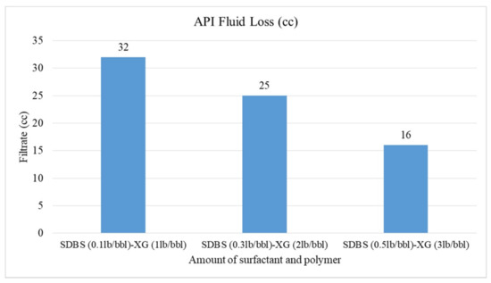
Figure 10.
Effect of SDBS surfactant on API fluid loss.
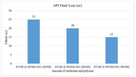
Figure 11.
Effect of HTAB surfactant on API fluid loss.

Figure 12.
API fluid loss of CGA fluid in present of salt.
The effect of increasing SDBS surfactant and XG polymer is shown in Figure 10. As can be seen, by increasing SDBS and XG together in CGA drilling fluid, the fluid loss will be reduced from 32 to 16 cc. Increasing the SDBS concentration causes the number of micro-bubbles in the CGA drilling fluids to increase. Subsequently, accumulation of micro-bubbles in API filter press reduces the fluid loss. XG polymer also has an important effect on reduction of filtration loss because of its viscosity. Increasing viscosity of fluids results in resistance to fluid flow.
The HTAB-based fluids have the same effect on reduction of filtration loss according to Figure 11. For these fluids, the fluid loss value reduces from 25 to 15 cc; the filtration loss for HTAB surfactant is less than SDBS surfactant (by comparison of Figure 10 and Figure 11); Bjorndalen and Kuru [30] also reported this reduction in their research but they observed some solid deposits in the HTAB-based fluid. In this research, no deposition of solid was observed, so it can be concluded that HTAB surfactant has more effect on filtration loss than SDBS surfactant.
As depicted in Figure 12, the filtration loss of HTAB-based fluid is 2 cc less than SDBS-based fluid in the presence of NaCl. It can be concluded that HTAB surfactant in presence of salt also has a better effect on reducing fluid loss; but this reduction is not very remarkable.
4. Conclusions
In this research, L36 array Taguchi design of experiments (DOE) was adopted to analyse experimental results based on stability (as performance parameter) of CGA drilling fluid generated with XG and PacR polymers and HTAB and SDBS surfactants. Also, size distribution, rheology and filtration loss of the CGA drilling fluid have been evaluated, from which the following conclusions are obtained:
- According to DOE results, polymer type is the most effective and surfactant type is the least effective parameter on stability.
- By using XG polymer, the stability increases and micro-bubbles are more stable and disperse in the fluid than PacR polymer, which in the presence of PacR the micro-bubbles of CGA are very unstable and the liquid phase of the fluid drain rapidly just after aphron generation.
- Both SDBS and HTAB surfactants have a relatively close effect on micro-bubble stability of CGAs fluid.
- Increasing salinity in CGA fluid reduces the stability and the micro-bubbles generated with HTAB surfactant in an electrolyte system are more stable than SDBS surfactant.
- The apparent and plastic viscosities, yield point and gel strength (initial and 10 min) of CGA drilling fluids increase with the increase of the concentration of surfactant and polymer.
- The HTAB surfactant reduces filtration loss of CGA drilling fluid more than SDBS surfactant in the presence of XG polymer
- In an electrolyte system, the filtration loss is more compared to a non-electrolyte system, this is because of reduction in the number of bubbles and less stability of micro-bubbles in presence of salt in the fluid.
The results obtained in this study can be used to design a CGA-based drilling fluid for a safe drilling operation.
Author Contributions
Conceptualization, S.A.H.-K., E.K. and B.D.; methodology, S.A.H.-K. and E.K.; software, S.A.H.-K. and E.K.; validation, S.A.H.-K., E.K. and B.D.; formal analysis, S.A.H.-K. and E.K.; investigation, S.A.H.-K. and E.K.; resources, S.A.H.-K., E.K. and B.D.; data curation, S.A.H.-K. and E.K.; writing—original draft preparation, S.A.H.-K. and E.K.; writing—review and editing, S.A.H.-K., E.K., B.D., A.A. and Z.M; visualization, E.K., B.D., A.A. and Z.M; supervision, E.K., B.D., A.A. and Z.M; project administration, E.K.; funding acquisition, E.K.
Funding
This research was funded by Iran National Science Foundation (INSF), grant number 96001276.
Acknowledgments
The authors wish to thank the Department of Petroleum Engineering, Amirkabir University of Technology for permission to use formation damage laboratory equipment.
Conflicts of Interest
The authors declare no conflict of interest.
References
- Sebba, F. Foams and Biliquid Foams, Aphrons; John Wiley & Sons Ltd: Chichester, UK, 1987. [Google Scholar]
- Save, S.V.; Pangarkar, V.G. Characterisation of colloidal gas aphrons. Chem. Eng. Commun. 1994, 127, 35–54. [Google Scholar] [CrossRef]
- Jauregi, P.; Gilmour, S.; Varley, J. Characterisation of colloidal gas aphrons for subsequent use for protein recovery. Chem. Eng. J. 1997, 65, 1–11. [Google Scholar]
- Brookey, T. Micro-Bubbles: New Aphron Drill.-In Fluid Technique Reduces Formation Damage in Horizontal Wells. In Proceedings of the SPE Formation Damage Control Conference, Lafayette, LA, USA, 8–19 February 1998. [Google Scholar]
- Ramirez, F.; Greaves, R.; Montilva, J. Experience using microbubbles-aphron drilling fluid in mature reservoirs of Lake Maracaibo. In Proceedings of the International Symposium and Exhibition on Formation Damage Control, Lafayette, LA, USA, 20–21 February 2002. [Google Scholar]
- Growcock, F.B. Enhanced wellbore stabilization and reservoir productivity with aphron drilling fluid technology; Department of Energy: Houston, TX, USA, 2005. [Google Scholar]
- Bjorndalen, N.; Kuru, E. Physico-Chemical Characterizationof Aphron Based Drilling Fluids. In Proceedings of the Canadian International Petroleum Conference, Calgary, AB, Canada, 7–9 June 2005. [Google Scholar]
- Keshavarzi, B.; Javadi, A.; Bahramian, A.; Miller, R. Formation and stability of colloidal gas aphron based drilling fluid considering dynamic surface properties. J. Petrol. Sci. Eng. 2019, 174, 468–475. [Google Scholar] [CrossRef]
- Huang, T.; Crews, J.B.; Agrawal, G. Nanoparticle pseudocrosslinked micellar fluids: Optimal solution for fluid-loss control with internal breaking. In Proceedings of the SPE International Symposium and Exhibiton on Formation Damage Control, Lafayette, LA, USA, 10–12 February 2010. [Google Scholar]
- Arabloo, M.; Shahri, M.P.; Zamani, M. Characterization of colloidal gas aphron-fluids produced from a new plant-based surfactant. J. Disper. Sci. Technol. 2013, 34, 669–678. [Google Scholar] [CrossRef]
- Tabzar, A.; Arabloo, M.; Ghazanfari, M.H. Rheology, stability and filtration characteristics of Colloidal Gas. Aphron fluids: Role of surfactant and polymer type. J. Nat. Gas Sci. Eng. 2015, 26, 895–906. [Google Scholar]
- Growcock, F.B.; Khan, A.M.; Simon, G.A. Application of water-based and oil-based aphrons in drilling fluids. In Proceedings of the International Symposium on Oilfield Chemistry, Houston, TX, USA, 5–7 February 2003. [Google Scholar]
- Alizadeh, A.; Khamehchi, E. Experimental investigation of the oil based Aphron drilling fluid for determining the most stable fluid formulation. J. Petrol. Sci. Eng. 2019, 174, 525–532. [Google Scholar] [CrossRef]
- Parthasarathy, R.; Jameson, G.; Ahmed, N. Bubble breakup in stirred vessels-predicting the Sauter mean diameter. Chem. Eng. Res. Des. 1991, 69, 295–301. [Google Scholar]
- Roy, D.; Valsaraj, K.; Kottai, S. Separation of organic dyes from wastewater by using colloidal gas aphrons. Sep. Sci. Technol. 1992, 27, 573–588. [Google Scholar] [CrossRef]
- Dai, Y.; Deng, T. Stabilization and characterization of colloidal gas aphron dispersions. J. Colloid Int. Sci. 2003, 261, 360–365. [Google Scholar] [CrossRef]
- Alizadeh, A.; Khamehchi, E. Modeling of micro-bubble surfactant multi-layer drilling fluid stability based on single bubble behavior under pressure and temperature in a deviated gas well. J. Nat. Gas Sci. Eng. 2015, 26, 42–50. [Google Scholar] [CrossRef]
- Alizadeh, A.; Khamehchi, E. A model for predicting size distribution and liquid drainage from micro-bubble surfactant multi-layer fluids using population balance. Colloid Polym. Sci. 2015, 293, 3419–3427. [Google Scholar] [CrossRef]
- Alizadeh, A.; Khamehchi, E. Stability modeling of water-based surfactant covered micro-bubble fluids. J. Surf. Deterg. 2016, 19, 165–171. [Google Scholar] [CrossRef]
- Alizadeh, A.; Khamehchi, E. Mathematical modeling of the colloidal gas aphron motion through porous medium, including colloidal bubble generation and destruction. Colloid Polym. Sci. 2016, 294, 1075–1085. [Google Scholar] [CrossRef]
- Alizadeh, A.; Khamehchi, E. Modeling of Micro-Bubble Drilling Fluid Stability: Micro-Bubble Surfactant Multi-Layer, Drilling Fluid Stability Based on Single Bubble Behavior; LAP Lambert Academic Publishing: Saarbrücken, Germany, 2016. [Google Scholar]
- Alizadeh, A.; Khamehchi, E. Numerical and experimental investigation of micro-bubble fluid infiltration in porous media. Colloid Polym. Sci. 2017, 295, 529–541. [Google Scholar] [CrossRef]
- Alizadeh, A.; Khamehchi, E. Mathematical modeling of the Colloidal Gas. Aphron transport through porous medium using the filtration theory. J. Nat. Gas Sci. Eng. 2017, 44, 37–53. [Google Scholar] [CrossRef]
- Khamehchi, E.; Tabibzadeh, S.; Alizadeh, A. Rheological properties of Aphron based drilling fluids. Petrol. Explor. Dev. 2016, 43, 1076–1081. [Google Scholar] [CrossRef]
- Sadeghialiabadi, H.; Amiri, M. A new stability index for characterizing the colloidal gas aphrons dispersion. Colloids Surf. A Physicochem. Eng. Asp. 2015, 471, 170–177. [Google Scholar] [CrossRef]
- Kuru, E.; Bjorndalen, N.; Jossy, E.; Alvarez, J.M. Reducing formation damage with microbubble-based drilling fluid: Understanding the blocking ability. J. Can. Petrol. Technol. 2008, 47, 11. [Google Scholar] [CrossRef]
- Nareh’ei, M.A.; Shahri, M.P.; Zamani, M. Preparation and characterization of colloidal gas aphron based drilling fluids using a plant-based surfactant. In Proceedings of the SPE Saudi Arabia Section Technical Symposium and Exhibition, Al-Khobar, Saudi Arabia, 8–11 April 2012. [Google Scholar]
- Arabloo, M.; Shahri, M.P. Experimental studies on stability and viscoplastic modeling of colloidal gas aphron (CGA) based drilling fluids. J. Petrol. Sci. Eng. 2014, 113, 8–22. [Google Scholar] [CrossRef]
- Arabloo Nareh’ei, M.; Pordel Shahri, M.; Zamani, M. Rheological and filtration loss characteristics of colloidal gas aphron based drilling fluids. J. Jap. Petrol. Ins. 2012, 55, 182–190. [Google Scholar] [CrossRef]
- Bjorndalen, N.; Kuru, E. Stability of microbubble-based drilling fluids under downhole conditions. J. Canadian Petrol. Tech. 2008, 47, 6. [Google Scholar] [CrossRef]
© 2019 by the authors. Licensee MDPI, Basel, Switzerland. This article is an open access article distributed under the terms and conditions of the Creative Commons Attribution (CC BY) license (http://creativecommons.org/licenses/by/4.0/).