
Scanning Electron Microscopy of Carbon Nanotube–Epoxy Interfaces: Correlating Morphology to Sulfate Exposure

 ,
,
Abstract
1. Introduction
2. Materials and Methods
2.1. Material and Specimen Fabrication
2.2. Aging Process
2.3. Microscopic Analysis
3. Result and Discussion
3.1. Salt Deposition
3.2. Degradations
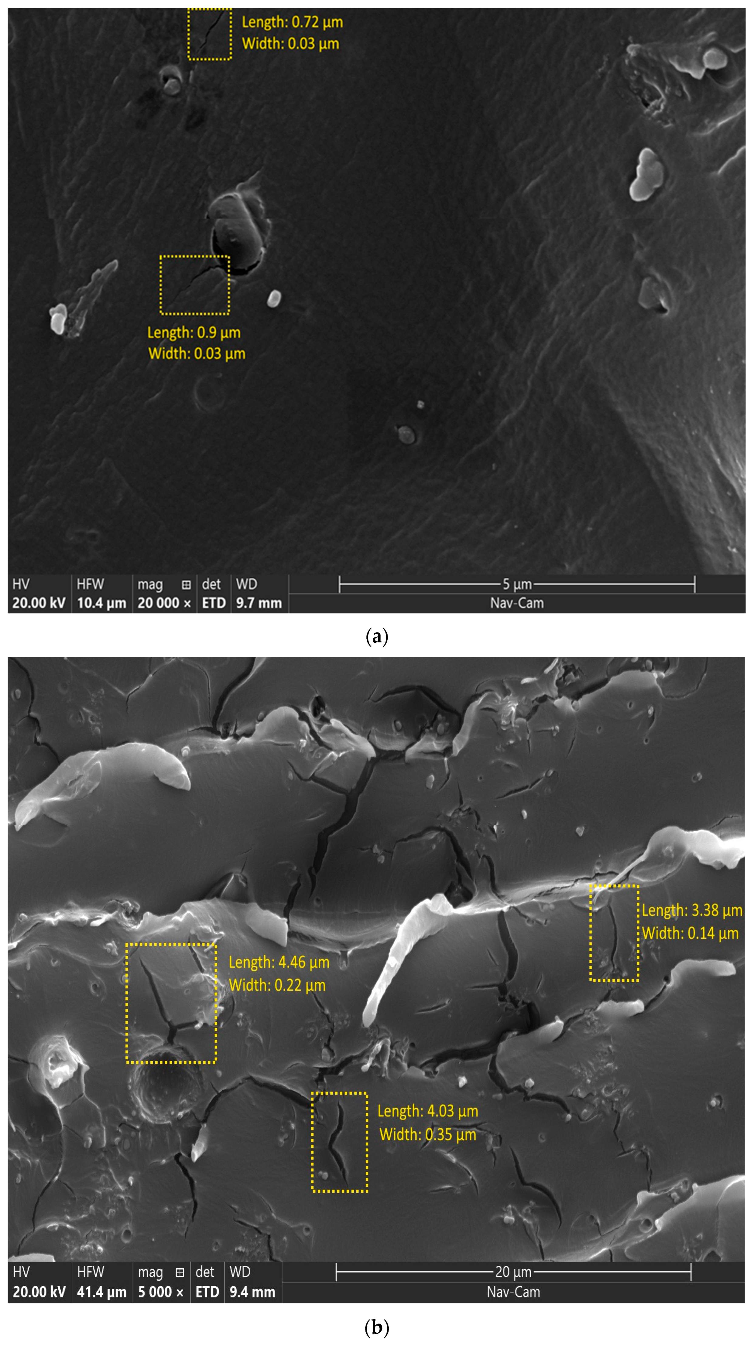
3.2.1. Cracks
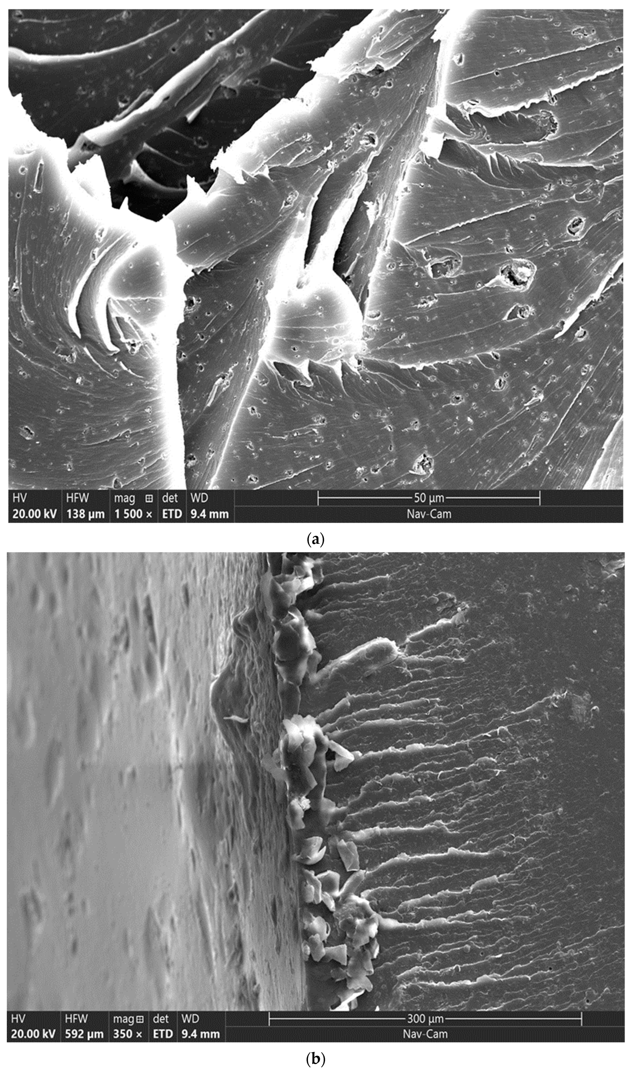
3.2.2. Punctures
3.3. Neat vs. MWCNT-Reinforced Specimens
4. Conclusions
Author Contributions
Funding
Data Availability Statement
Acknowledgments
Conflicts of Interest
References
- Neville, A. The confused world of sulfate attack on concrete. Cem. Concr. Res. 2004, 34, 1275–1296. [Google Scholar] [CrossRef]
- Whittaker, M.; Black, L. Current knowledge of external sulfate attack. Adv. Cem. Res. 2015, 27, 532–545. [Google Scholar] [CrossRef]
- Benosman, A.S.; Taïbi, H.; Senhadji, Y.; Mouli, M.; Belbachir, M.; Bahlouli, M. Plastic waste particles in mortar composites: Sulfate resistance and thermal coefficients. Prog. Rubber Plast. Recycl. Technol. 2017, 33, 171–202. [Google Scholar] [CrossRef]
- May, C. Epoxy Resins: Chemistry and Technology; Routledge: Oxford, UK, 2018. [Google Scholar]
- Silva, P.; Fernandes, P.; Sena-Cruz, J.; Xavier, J.; Castro, F.; Soares, D.; Carneiro, V. Effects of different environmental conditions on the mechanical characteristics of a structural epoxy. Compos. Part B Eng. 2016, 88, 55–63. [Google Scholar] [CrossRef]
- Tanks, J.; Naito, K. UV durability assessment of a thermoplastic epoxy-based hybrid composite rod for structural reinforcement and retrofitting. J. Build. Eng. 2022, 48, 103922. [Google Scholar] [CrossRef]
- Dai, H. Carbon nanotubes: Opportunities and challenges. Surf. Sci. 2002, 500, 218–241. [Google Scholar] [CrossRef]
- Pettes, M.T.; Shi, L. Thermal and structural characterizations of individual single-, double-, and multi-walled carbon nano-tubes. Adv. Funct. Mater. 2009, 19, 3918–3925. [Google Scholar] [CrossRef]
- Naqi, A.; Abbas, N.; Zahra, N.; Hussain, A.; Shabbir, S.Q. Effect of multi-walled carbon nanotubes (MWCNTs) on the strength development of cementitious materials. J. Mater. Res. Technol. 2019, 8, 1203–1211. [Google Scholar] [CrossRef]
- Arunkumar, T.; Karthikeyan, R.; Subramani, R.R.; Viswanathan, K.; Anish, M. Synthesis and characterisation of multi-walled carbon nanotubes (MWCNTs). Int. J. Ambient. Energy 2020, 41, 452–456. [Google Scholar] [CrossRef]
- Kim, S.D.; Kim, J.W.; Im, J.S.; Kim, Y.H.; Lee, Y.S. A comparative study on properties of multi-walled carbon nanotubes (MWCNTs) modified with acids and oxyfluorination. J. Fluor. Chem. 2007, 128, 60–64. [Google Scholar] [CrossRef]
- Devi, R.; Gill, S.S. A squared bossed diaphragm piezoresistive pressure sensor based on CNTs for low pressure range with enhanced sensitivity. Microsyst. Technol. 2021, 27, 3225–3233. [Google Scholar] [CrossRef]
- Liew, K.M.; Wong, C.H.; He, X.Q.; Tan, M.J.; Meguid, S.A. Nanomechanics of single and multiwalled carbon nanotubes. Phys. Rev. B 2004, 69, 115429. [Google Scholar] [CrossRef]
- Xue, Y.; Zheng, S.; Sun, Z.; Zhang, Y.; Jin, W. Alkaline electrochemical advanced oxidation process for chromium oxidation at graphitized multi-walled carbon nanotubes. Chemosphere 2017, 183, 156–163. [Google Scholar] [CrossRef] [PubMed]
- Saito, T.; Matsushige, K.; Tanaka, K. Chemical treatment and modification of multi-walled carbon nanotubes. Phys. B Condens. Matter 2002, 323, 280–283. [Google Scholar] [CrossRef]
- Rafique, I.; Kausar, A.; Anwar, Z.; Muhammad, B. exploration of epoxy resins, hardening systems, and epoxy/carbon nanotube composite designed for high performance materials: A review. Polym. Technol. Eng. 2016, 55, 312–333. [Google Scholar] [CrossRef]
- Fernando, N. Impact of Nano-Modified Epoxy on Cfrp-Strengthened Concrete Bond in Aggressive Environments. 2024. Available online: https://orca.cardiff.ac.uk/id/eprint/171106/ (accessed on 22 June 2025).
- Shen, W.; Feng, L.; Liu, X.; Luo, H.; Liu, Z.; Tong, P.; Zhang, W. Multiwall carbon nanotubes-reinforced epoxy hybrid coatings with high electrical conductivity and corrosion resistance prepared via electrostatic spraying. Prog. Org. Coat. 2016, 90, 139–146. [Google Scholar] [CrossRef]
- Dresselhaus, M.; Dresselhaus, G.; Jorio, A. Unusual properties and structure of carbon nanotubes. Annu. Rev. Mater. Res. 2004, 34, 247–278. [Google Scholar] [CrossRef]
- Kukovecz, Á.; Kozma, G.; Kónya, Z. Multi-walled carbon nanotubes. In Springer Handbook of Nanomaterials; Springer: Berlin/Heidelberg, Germany, 2013; pp. 147–188. [Google Scholar]
- Ajayan, P.M.; Lijima, S. Capillarity-induced filling of carbon nanotubes. Nature 1993, 361, 333–334. [Google Scholar] [CrossRef]
- Ramachandran, K.; Boopalan, V.; Bear, J.C.; Subramani, R. Multi-walled carbon nanotubes (MWCNTs)-reinforced ceramic nanocomposites for aerospace applications: A review. J. Mater. Sci. 2022, 57, 3923–3953. [Google Scholar] [CrossRef]
- Aslan, A.; Salur, E.; Düzcükoğlu, H.; Şahin, Ö.S.; Ekrem, M. The effects of harsh aging environments on the properties of neat and MWCNT reinforced epoxy resins. Constr. Build. Mater. 2021, 272, 121929. [Google Scholar] [CrossRef]
- Karakuzu, R.; Kanlioglu, H.; Deniz, M.E. Environmental effects on mechanical properties of glass-epoxy composites. Mater. Test. 2014, 56, 355–361. [Google Scholar] [CrossRef]
- Deniz, M.E.; Ozen, M.; Ozdemir, O.; Karakuzu, R.; Icten, B.M. Environmental effect on fatigue life of glass–epoxy composite pipes subjected to impact loading. Compos. Part B Eng. 2013, 44, 304–312. [Google Scholar] [CrossRef]
- Wei, B.; Cao, H.; Song, S. Tensile behavior contrast of basalt and glass fibers after chemical treatment. Mater. Des. 2010, 31, 4244–4250. [Google Scholar] [CrossRef]
- Yan, L.; Chouw, N. Effect of water, seawater and alkaline solution ageing on mechanical properties of flax fabric/epoxy composites used for civil engineering applications. Constr. Build. Mater. 2015, 99, 118–127. [Google Scholar] [CrossRef]
- Li, Y.; Cao, J. The impact of multi-walled carbon nanotubes (MWCNTs) on macrophages: Contribution of MWCNT characteristics. Sci. China Life Sci. 2018, 61, 1333–1351. [Google Scholar] [CrossRef] [PubMed]
- Kotnarowska, D. Epoxy coating destruction as a result of sulphuric acid aqueous solution action. Prog. Org. Coat. 2010, 67, 324–328. [Google Scholar] [CrossRef]
- Rudawska, A. The impact of the acidic environment on the mechanical properties of epoxy compounds in different conditions. Polymers 2020, 12, 2957. [Google Scholar] [CrossRef] [PubMed]
- Jalaie, A.; Afshaar, A.; Mousavi, S.B.; Heidari, M. Investigation of the release rate of biocide and corrosion resistance of vinyl-, acrylic-, and epoxy-based antifouling paints on steel in marine infrastructures. Polymers 2023, 15, 3948. [Google Scholar] [CrossRef] [PubMed]
- Shcherbakov, A.S.; Mostovoy, A.S.; Yakovlev, N.A.; Arzamastsev, S.V. Effect of carbon nanotube functionalization on the physicochemical and mechanical properties of modified fiber-reinforced composites based on an epoxy resin. Russ. J. Appl. Chem. 2021, 94, 1080–1087. [Google Scholar] [CrossRef]
- Chowdhury, H.; Saha, A.; Hasan, M.; Haider, J. Effects of Alkaline and Carboxilated Graphene Oxide (CGO) Treatment on Mechanical, Thermal, and Electrical Properties of Jute Fiber-Reinforced Epoxy Composites. J. Compos. Sci. 2025, 9, 104. [Google Scholar] [CrossRef]
- Liever, A.; Liu, Y.; Vemuganti, S. Effect of immediate curing at elevated temperatures on the tensile and interfacial properties of carbon fiber-epoxy composites. Funct. Compos. Struct. 2024, 6, 035001. [Google Scholar] [CrossRef]
- Tang, L.-C.; Zhang, H.; Han, J.-H.; Wu, X.-P.; Zhang, Z. Fracture mechanisms of epoxy filled with ozone functionalized multi-wall carbon nanotubes. Compos. Sci. Technol. 2011, 72, 7–13. [Google Scholar] [CrossRef]
- Mirjalili, V.; Hubert, P. Modelling of the carbon nanotube bridging effect on the toughening of polymers and experimental verification. Compos. Sci. Technol. 2010, 70, 1537–1543. [Google Scholar] [CrossRef]
- Al-Maharma, A.Y.; Sendur, P.; Al-Huniti, N. Critical review of the factors dominating the fracture toughness of CNT reinforced polymer composites. Mater. Res. Express 2018, 6, 012003. [Google Scholar] [CrossRef]
- Seshadri, M.; Saigal, S. Crack bridging in polymer nanocomposites. J. Eng. Mech. 2007, 133, 911–918. [Google Scholar] [CrossRef]


| Phase 1 | Phase 2 | Remarks | |
|---|---|---|---|
| Salt crystals | |||
| Neat | Significant (15 ± 5.77) µm dia | Low (1 ± 0.24) µm dia | Salt crystals decreased in size 15 times |
| Reinforced | Very Low (0.1 ± 0.003) µm dia | Significant (20 ± 3.26) µm dia | Salt crystals increased in size by 200 times |
| Crack degradation | |||
| Neat | - | - | No significant cracks |
| Reinforced | Width of (0.03 ± 0) µm | Width of (0.24 ± 0.01) µm | Cracks increased 5 times in length and 8 times in width |
| Puncture degradation | |||
| Neat | (2 ± 0.96) µm dia | (4 ± 2.8) µm dia | Size of punctures increased by 2 times |
| Reinforced | (1.5 to 3.5) µm dia | (1 to 4.5) µm dia | Size of punctures remained almost stagnant |
Disclaimer/Publisher’s Note: The statements, opinions and data contained in all publications are solely those of the individual author(s) and contributor(s) and not of MDPI and/or the editor(s). MDPI and/or the editor(s) disclaim responsibility for any injury to people or property resulting from any ideas, methods, instructions or products referred to in the content. |
© 2025 by the authors. Licensee MDPI, Basel, Switzerland. This article is an open access article distributed under the terms and conditions of the Creative Commons Attribution (CC BY) license (https://creativecommons.org/licenses/by/4.0/).
Share and Cite
Adhikari, S.; Myers, B.M.; Tuck, B.L.; Dawson, C.; Cipriano, J.R.; Ahlert, J.F.; Thwala, M.; Griffin, M.A.; Yadak, O.; Alfailakawi, O.A.; et al. Scanning Electron Microscopy of Carbon Nanotube–Epoxy Interfaces: Correlating Morphology to Sulfate Exposure. J. Compos. Sci. 2025, 9, 392. https://doi.org/10.3390/jcs9080392
Adhikari S, Myers BM, Tuck BL, Dawson C, Cipriano JR, Ahlert JF, Thwala M, Griffin MA, Yadak O, Alfailakawi OA, et al. Scanning Electron Microscopy of Carbon Nanotube–Epoxy Interfaces: Correlating Morphology to Sulfate Exposure. Journal of Composites Science. 2025; 9(8):392. https://doi.org/10.3390/jcs9080392
Chicago/Turabian StyleAdhikari, Sijan, Braiden M. Myers, Bryce L. Tuck, Courtney Dawson, Joey R. Cipriano, Jules F. Ahlert, Menziwokuhle Thwala, Mia A. Griffin, Omar Yadak, Osama A. Alfailakawi, and et al. 2025. "Scanning Electron Microscopy of Carbon Nanotube–Epoxy Interfaces: Correlating Morphology to Sulfate Exposure" Journal of Composites Science 9, no. 8: 392. https://doi.org/10.3390/jcs9080392
APA StyleAdhikari, S., Myers, B. M., Tuck, B. L., Dawson, C., Cipriano, J. R., Ahlert, J. F., Thwala, M., Griffin, M. A., Yadak, O., Alfailakawi, O. A., Ritz, M. S., Wright, S. M., Volz, J., & Vemuganti, S. (2025). Scanning Electron Microscopy of Carbon Nanotube–Epoxy Interfaces: Correlating Morphology to Sulfate Exposure. Journal of Composites Science, 9(8), 392. https://doi.org/10.3390/jcs9080392