Article

Numerical and Experimental Study on the Deformation of Adaptive Elastomer Fibre-Reinforced Composites with Embedded Shape Memory Alloy Wire Actuators

1
Institute of Lightweight Engineering and Polymer Technology (ILK), TUD Dresden University of Technology, Holbeinstraße 3, 01307 Dresden, Saxony, Germany
2
Center for Scalable Data Analytics and Artificial Intelligence Dresden/Leipzig (ScaDS.AI), TUD Dresden University of Technology, Strehlener Straße 12-14, 01069 Dresden, Saxony, Germany
3
Institute of Textile Machinery and High Performance Material Technology (ITM), TUD Dresden Universtity of Technology, Hohe Straße 6, 01062 Dresden, Saxony, Germany
*
Author to whom correspondence should be addressed.
J. Compos. Sci. 2025, 9(7), 371; https://doi.org/10.3390/jcs9070371
Submission received: 23 June 2025 / Revised: 9 July 2025 / Accepted: 12 July 2025 / Published: 16 July 2025
(This article belongs to the Special Issue Theoretical and Computational Investigation on Composite Materials)

Abstract

In this work, a finite element modelling methodology is presented for the prediction of the bending behaviour of a glass fibre-reinforced elastomer composite with embedded shape memory alloy (SMA) wire actuators. Three configurations of a multi-layered composite with differences in structural stiffness and thickness are experimentally and numerically analysed. The bending experiments are realised by Joule heating of the SMA, resulting in deflection angles of up to 58 deg. It is shown that a local degradation in the structural stiffness in the form of a hinge significantly increases the amount of deflection. Modelling is fully elaborated in the finite element software ANSYS, based on material characterisation experiments of the composite and SMA materials. The thermomechanical material behaviour of the SMA is modelled via the Souza–Auricchio model, based on differential scanning calorimetry (DSC) and isothermal tensile experiments. The methodology allows for the consideration of an initial pre-stretch for straight-line positioned SMA wires and an evaluation of their phase transformation state during activation. The results show a good agreement of the bending angle for all configurations at the activation temperature of 120 °C reached in the experiments. The presented methodology enables an efficient design and evaluation process for soft robot structures with embedded SMA actuator wires.

1. Introduction

The demand for automation in industry and society has recently led to an increasing trend in the development of soft robots, which offer various key advantages over conventional robots [1]. Bio-inspired soft robots show a unique potential to imitate the deformation and motion mechanics of natural biological systems [2,3]. Typically, soft robot structures consist of so-called “soft” materials, which exhibit mechanical properties comparable to those of living tissues. For this, silicone-based elastomer materials are particularly suitable as they offer excellent flexibility, adaptability, and biocompatibility [4]. The realisation of combined shape and stiffness adaptability can be achieved by various actuator designs. Actuator elements made of shape memory alloys (SMAs) are well suited for application in soft robotic structures as they offer high energy density, diverse form factors, and the ability to be electrically activated by miniaturized and integrated electronics [5,6]. SMAs exhibit unique and complex thermomechanical material characteristics, such as superelasticity (SE) and a shape memory effect (SME) [6,7]. SMAs are able to remember and to recover their original shape with increasing stress and temperature, which is caused by an inherent solid-to-solid phase transformation, from the martensite phase to the austenite phase, which is accompanied by a change in material properties [8]. Hereby, transformation temperatures increase with stress, as the dissipated energy increases as well, caused by the energy required to transform the crystal structure of the SMA material. The capability of the SMA for shape recovery increases with increasing temperature, with the superelastic effect being evident [9]. Recent advances in shape memory materials and additive manufacturing have enabled 4D printing, where 3D-printed structures can change their shape and/or properties over time in response to external stimuli, opening new possibilities in robotics, biomedicine, and functional materials [10,11,12,13].
The design and evaluation process for soft structures with embedded SMA actuators is currently facing various challenges, where the key aspects include achieving a function-oriented structural embedding technique for SMA actuators that enables damage-free and reliable force transmission by thermal activation [14,15,16,17], energy efficient activation and control of the SMA actuators, e.g., by Joule heating with an electrical current [18,19,20], and the development of adequate simulation models of SMA-based adaptive structures for prediction of the deflection behaviour, accompanied by the accurate modelling of characteristic material phenomena [21,22,23]. Here, the extent of deflection is mainly influenced by the structural stiffness, the positioning and alignment of the SMA actuator, and the interaction between the actuator and the structure itself [24]. Currently, the deformation behaviour of such structures is mainly explored by empirical relations on the basis of elaborate experimental work [25,26,27]. However, highly complex and multi-linked adaptive soft robotic systems require more advanced and sophisticated models to predict the amount of deformation and to further explore the existing large design space of such systems. Finite element modelling techniques at the structural level are well suited to significantly reduce the required experimental work, which further increases the efficiency of the design phase when considering the interaction between the structure and the SMA actuator. In addition to experiments, accurate and predictive finite element simulations allow a huge broadening of the database, which is needed for the development of advanced models such as genetic algorithm models [28].
The utilisation of an analysis methodology based on finite element analysis (FEA) for elastomer-based composites with embedded SMA actuators requires a profound understanding of the mechanical material behaviour of the overall structure and especially of the complex thermomechanical behaviour of the actuator. Soft robotic structures made of silicone-based polymers or hydrogels often exhibit time-dependent hyper-viscoelastic properties [29,30]. For these, various models exist that are able to describe strong isotropic non-linear elastic material behaviour [31]. Most composite materials show orthotropic material behaviour, which is significantly influenced by reinforcement fibres [32]. Sufficiently accurate modelling of an SMA material’s behaviour plays a decisive role with regard to understanding the deformation behaviour of an SMA-based adaptive structure. There exist numerous macroscopic phenomenological constitutive models that do not denote the phase transformation mechanism applicable at the structural level [33,34,35,36,37,38]. The utilisation of such material models enables a predictive and accurate description of the deflection behaviour due to activation of the SMA actuator element for adaptive structures [39,40,41].
In this work, a finite element modelling methodology is elaborated for a glass fibre-reinforced elastomer-based composite with an embedded shape memory alloy wire actuator. First, modelling of the mechanical behaviour of the SMA wire actuator and the adaptive composite with its constituents is carried out on the basis of fundamental characterisation experiments. Afterwards, for three configurations of multi-layered composites, a methodology is elaborated for the analysis of the bending deformation due to the thermal activation of the SMA actuator. Finally, the results are compared with the experimental data for model validation, and the potential of finite element analysis is shown with regard to the broadening of the understanding of such adaptive structures.

2. Materials and Experimental Results

2.1. Shape Memory Alloy

In this work, a nickel–titanium-based shape memory alloy wire material is considered, which was supplied by SAES Getters S.p.A. The SMA wire material had a diameter of 0.3 mm and an as-delivered pre-stretch of 4.4% realised by thermomechanical cycling of the wire at a constant load of 400 MPa. In previous work, the complex thermomechanical material behaviour of the SMA was fundamentally characterised by differental scanning calorimetry (DSC) to determine the phase transformation temperatures, by isothermal tensile experiments for the derivation of the modulus of elasticity and corresponding transformation strains and by constant strain tensile tests to identify the resultant actuation force due to thermal activation [42]. The experimentally derived phase transformation temperatures for the SMA wire material are listed in Table 1. It should be noted that these transformation temperatures are affected by the stress applied during the SMA application. Therefore, a stress-induced shift of the transformation temperatures must be taken into account when modelling the thermomechanical behaviour of the SMA.

2.2. Polymer

A dimethylpolysiloxane (PDMS) silicone elastomer material, Sylgard 184, is considered as the base material in this work to realise an adaptive structure with soft flexural bending behaviour. This polymer material is used in broad industrial applications and offers good mechanical properties that can be controlled and adjusted through a simple curing process [43]. As the experimental determination of flexural or bending properties for soft materials is difficult, the considered PDMS material, degassed and cured at 23 °C, was tested under uniaxial tensile loading in previous studies [44]. The operating temperature range of the polymer is between −55 °C and 200 °C.

2.3. Composite

A composite material is considered, which consists of PDMS polymer as the matrix material with bi-directional glass fibre (GF) reinforcement. The multi-layered fabric preforms are realised via knitting technology [44,45]. The preform contains GF rovings with a density of 410 tex and twisted GF yarns with a density of 2 × 136 tex. The flat knitting textile formation process offers the possibility of integrating the SMA wire material into the preform during the textile forming process. Before this, the SMA wire material is integrated into a polytetrafluoroethylene (PTFE) hose to thermally protect the PDMS material during the thermal activation of the SMA wire material and to ensure a reliable, undamaged, and low friction connection between the SMA and the composite. The PTFE hose has an inner diameter of 0.5 mm and an outer diameter of 0.76 mm. The process enables the SMA wire material to be integrated into a one-sided meander shape. A schematic illustration of the fabric preform with a single one-sided meander-shaped embedded SMA wire is shown in Figure 1. More details of the process parameters, preform properties, and bending behaviour can be found in [44,45].

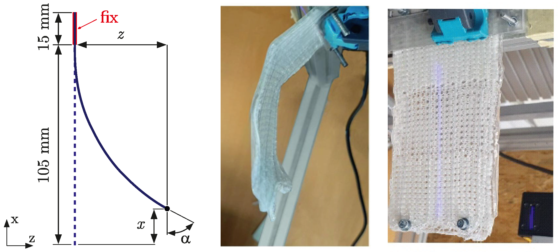
2.4. Specimen with Embedded SMA Actuators

Experimental analysis of the characteristic bending and deflection behavior was investigated in more detail by using sheet-shaped panel specimens [44,45]. The specimen consists of one pure PDMS layer in combination with one single composite layer, in which the SMA wire is embedded in a one-sided meander shape with two loops with a radius r of approx. 10 mm. A schematic illustration of the specimen is shown in Figure 1. Three different specimen configurations are considered, each with different fibre compositions in the weft direction, resulting in different specimen thicknesses c, as well as differences in the resulting flexural properties. Figure 2 schematically shows the layered structure of the preform over its thickness for the investigated specimen configurations V1, V2, and V2h. In comparison to V1, V2 and V2h only contain GF rovings in the weft direction. All specimens exhibit a total length a of 120 mm and a width b of 80 mm, where the SMA wire is positioned symmetrically in the centre. The total specimen thickness c is defined by the PDMS layer and the composite layer, where the thickness of each layer is assumed to be the same. In contrast to configuration V1, which shows a total thickness c of 2 mm, configuration V2 and V2h show a thickness of 2.5 mm due to the higher fibre content in the composite layer (additional GF rovings in the weft direction). In contrast to configuration V1 and V2, configuration V2h shows a local varying bending stiffness centrally over a length of d along its specimen length a, due to a local different fibre composition in the preform. In the centre, along the specimen length, the preform shows a lower fibre content due to the absence of GF rovings in the weft direction, which results in a lower bending stiffness compared to the off-centre sections. Such areas with low stiffness may act as a solid body hinge enabling more efficient activation behaviour due to a larger structural deflection. The textile preform with embedded SMA wire after the textile forming process is shown for specimen configurations V2 and V2h in Figure 3. As configuration V1 is structurally similar to V2, it is not illustrated separately for reasons of clarity and conciseness.
For the actuation and deformation experiments, the specimens are firmly clamped on one side in the vertical direction, on the side on which the SMA wires lead out of the specimen (Figure 4). The clamping length here is 15 mm. In the so-called “activation” step of the specimen, to obtain a deflection realised by the SMA actuator, the SMA wires are heated up via a conventional resistive electric heating technique, by applying a small voltage of approx. 14 V, resulting in a current of 2 A. Specimens V1 and V2 are activated in cycles, with an activation time of 5 s, followed by a deactivation phase of 5 s. In contrast, the deactivation phase for V2h is 10 s. The activation process heats the SMA wire up to a temperature of approx. 120 °C, which was contactlessly measured by a thermal imaging camera in previous studies [46]. Here, it should be noted that the temperature of the embedded SMA wire is assumed to be slightly higher than the contactless measured data on the specimen surface due to the thermal insulation effects of the PDMS and composite material. The lateral deflection of the specimen tip s and the deflection angle α at the free end of the deformed specimen shape are measured via a laser scanning technique. For each specimen configuration, one single test with multiple activation cycles is carried out. Further details on the experimental procedure can be found in [44,45].
Figure 3. Textile preform for specimen configuration [47].
Jcs 09 00371 g003
Figure 4. Measurement of angular deflection and displacement (left), deformed V1 specimen with activated SMA actuator wires [44] (middle), and V1 specimen in un-activated state with projected laser scan line (right) [47].
Jcs 09 00371 g004
The thermal activation of the specimen leads to a bending deformation with a maximum deflection angle α (Figure 5). Specimen configuration V1 shows the largest deflection angle of approx. 58 deg. With an angle of 28 deg, configuration V2 shows the lowest deflection angle. In contrast to V2, configuration V2h shows the advantage of a hinge area to increase the deflection, resulting in a deflection angle of approx. 41 deg. In each of the cycles, almost the same deflection angle α is achieved within the limits of accuracy during activation. In the cooling phase (deactivation), however, a complete deformation back to the initial state can still be observed in the first two cycles for V1 and V2h (at 10 s and 20 s), whereby a residual deformation after cooling can be observed in further cycles. The observation of such a residual deformation can be attributed to the time-dependent viscoelastic effects in the PDMS material, to stiffness loss due to material damage, as well as to the functional fatigue of the SMA wire actuator. Configuration V2 shows a residual deformation after cooling, already after the first cycle. This is caused by progressive damage in the form of delamination effects with each additional activation cycle, which reduces the overall stiffness of the composite specimen, and the resulting restoring forces are no longer sufficient to stretch the SMA wire back to its initial length in the martensite phase.

3. Material Modelling

3.1. Shape Memory Alloy

The complex mechanical behaviour of the SMA wire material, dependent on the temperature, is modelled via a three-dimensional thermomechanical constitutive material model based on the work of Souza and Auricchio [35,48,49] that is available in the finite element software ANSYS® Enterprise Mechanical 2023 R1. In the following, the model is briefly described in terms of its parameters and utilisation on a structural level. More information about the model can be found in [50,51]. The macroscopic phenomenological model is based on the theory of irreversible thermodynamics and the small strain regime. A Helmholtz free energy function Ψ is defined for the model as follows:
Ψ ( ε , ε t r , T ) = 1 2 ( ε ε t r ) : D : ( ε ε t r ) + τ M ( T ) | | ε t r | | + 1 2 h | | ε t r | | 2 + I ε t r ( ε t r ) ,
where the total strain ε and temperature T are defined as external variables, and the transformation strain ε t r is the internal variable with its deviatoric part ε t r . Here, | | · | | denotes the Euclidian norm, D is the material elastic stiffness tensor, τ M ( T ) is a function of temperature, h is a material parameter related to the hardening of the material during transformation, and I ε t r ( ε t r ) is an indicator function introduced to satisfy the constraint on the transformation strain norm. Under uniaxial loading, it is assumed that the transformation strain ε t r fulfills the following saturation condition:
0 | | ε t r | | ε ¯ L ,
which means that the transformation strain ε t r ranges between a zero state, where no oriented martensite is present, and the maximum transformation strain ε ¯ L , where the material is completely transformed into oriented martensite. The function of the temperature τ M ( T ) is defined as β ( T T 0 ) + with scaling parameter β and reference temperature T 0 , where · + is the positive part of the argument. The indicator function I ε t r ( ε t r ) needs to satisfy the transformation condition, which is 0 for 0 | | ε t r | | ε L or else + . The elastic stiffness tensor D can be expressed as a function of the transformation strain ε t r as follows:
D = φ · ( D M D A ) + D A with φ = | | ε t r | | ε ¯ L ,
with the components for martensite state D M and austenite state D A . It is assumed that D = D M if the material is completely present as martensite, and D = D A if austenite is fully present. Accordingly, the martensite volume fraction φ ranges from 0 to 1.
Under the assumption of isothermal conditions and fully isotropic material behaviour, the model requires only nine parameters to model the SME (Table 2). These parameters are determined via stress–strain curves from previously performed isothermal tensile tests at different temperatures [42]. In Figure 6 exemplary stress–strain curves for two specific temperatures are shown. Reference temperature T 0 indicates a temperature up to which the SMA material shows a pseudo-plastic deformation behaviour. In contrast to this, the SMA material exhibits a pseudo-elastic material behaviour for temperatures above T 0 . For both cases, the Young’s modulus E at the beginning and the Young’s modulus for martensite E M after phase transformation can be calculated via the tangent method. The elastic limit R is determined via the critical stress points σ t , 0 under tensile loading and σ c , 0 under compression loading:
R = 2 6 3 · σ c , 0 · σ t , 0 σ c , 0 σ t , 0 .
In this work, no asymmetry between tensile and compressive behavior is assumed with σ c , 0 = σ t , 0 . Accordingly, the Lode parameter m is defined as zero, which controls the tension–compression asymmetry. The hardening parameter h is calculated via the characteristic stress points σ t , 0 and σ t , 1 , as well as the corresponding maximum transformation strain ε ¯ L :
h = 2 3 · σ t , 1 σ t , 0 ε L with ε ¯ L = 3 2 · ε L .
The scaling factor β is determined for a given reference temperature T 0 via the following formula:
β = 2 3 · σ t , 0 ( T ) σ t , 0 ( T 0 ) ) ( T T 0 ) .
Isothermal tensile experiments were conducted below A s at 23 °C and 60 °C and above A f at 90 °C and 130 °C. The reason for this is to capture the linear increase in the critical stress levels for phase transformation with temperature in order to derive the required scaling parameter β for modelling this linear relationship (similar to the Clausius–Clapeyron coefficient [52]). Therefore, four parameter sets for each testing temperature are derived from the experimental stress–strain data according to the previously mentioned formulas. Furthermore, the parameters are calibrated for each temperature via a single element test under uniaxial tensile loading condition. As expected, the SMA material exhibits a pseudo-plastic deformation behaviour below A s with 23 °C and 60 °C, which results in the definition of a reference temperature T 0 equal to the testing temperature for each parameter set. The reference temperature T 0 for the remained parameter sets above A s is kept constant at 60 °C, where the characteristic pseudo-elastic behaviour is controlled by the scaling factor β . For all parameter sets, the Young’s modulus for martensite E M , scaling factor β , maximum transformation strain ε ¯ L , and Lode parameter m are kept constant. The final calibrated material parameters for each testing temperature are listed in Table 2. With regard to the elastic modulus, it should be noted that the stiffness increases at higher temperatures due to the dominance of the austenite phase. Corresponding stress–strain data from the analysis in comparison with the experimental data are shown in Figure 7.

3.2. Polymer

Stress–strain data of the PDMS material derived from previous tensile tests show a clear hyperelastic material behavior [47]. For this work, this is acceptable, as the half of the specimen made of pure PDMS is mainly subjected to tensile load during activation, so that a characterisation under compressive loading is not required. The Yeoh constitutive model is proposed to model the strong non-linear material behaviour [53]. This model is based on the strain energy potential
W = i = 1 N c i 0 I 1 ¯ 3 i + k = 1 N 1 D k J 1 2 k ,
where I 1 is the first invariant of the Cauchy–Green strain tensor, and J is the volume ratio after and before deformation. The PDMS material is considered incompressible, resulting in J = 1. Here, the third-order model with N = 3 is applied to describe the distinct s-shaped stress–strain behaviour of the PDMS material (Figure 8). Temperature dependence is not considered here, as it is assumed that the PTFE hose prevents a heat transfer from the SMA to PDMS in a significant extent. The Yeoh model parameters corresponding for the PDMS are calibrated against the experimental stress–strain behaviour and are summarised in Table 3.

3.3. Composite

The GF/PDMS composite material is regarded as a homogeneous continuum, whereby it can be assumed that the glass fibres dominate the composite response in both fibre directions. In order to characterise the bending stiffness and subsequent calibration of the composite material, four-point bending tests, according to DIN 14125, were carried out for configuration V1 and V2 prior to this work [44]. According to the results of the experimental observations, a linear elastic material behaviour is assumed for the composite material. The elastic modulus for the composite material for V1 and V2 (Table 4) is calibrated to match the measured force–displacement response sufficiently closely, with the corresponding analysis–experiment comparison shown in Figure 9.

4. Numerical Modelling of Deformation Experiments

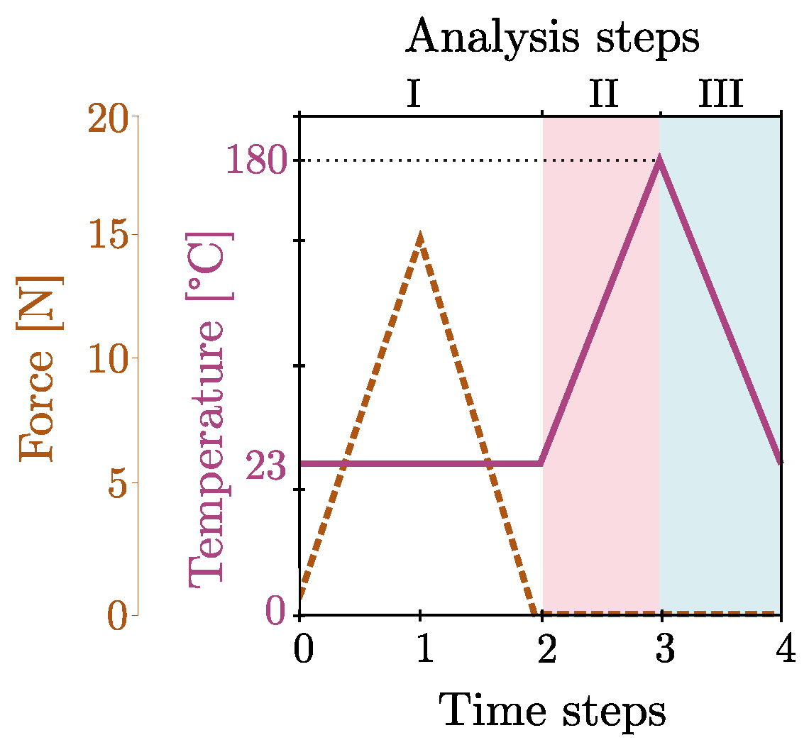
4.1. Multi-Step Analysis

For the finite element analyses, the backward Euler integration method (or implicit Euler method) is applied to solve the stress update and consistent tangent stiffness matrix, according to the demands of the proposed material model for the SMA actuator [54]. The non-symmetric Newton–Raphson iteration method (NROPT, UNSYM) is used to solve the non-linear problem, with automatic time-stepping ranging from 1 to 10 substeps. In addition, the stiffness matrix is recalculated during deformation to take into account the effects of large deformations.
According to the test setup, a multi-step non-linear analysis with activation and deactivation of the SMA actuator is carried out over several activation/de-activation cycles (Figure 10). In contrast to the experiments, the analysis procedure contains a single additional initial step in which the SMA wire is pre-stretched in the lengthwise direction. This is caused by the fact that the material model for the SMA in its implemented form does not support the use of previous analysis results such as pre-strains as initial state variables. This limits the application potential of the proposed methodology to only straight aligned SMA wire actuators as such pre-stretching is hard to realize in the analysis for complex shaped or non-straight aligned SMA actuator elements.
Here, the SMA wire is stretched with a force of 15 N to initiate the material-specific maximal pre-strain of approx. 3.3%. In the initial analysis step (I), the SMA wire is stretched lengthwise via a uniaxial force boundary condition, which results in a pseudo-plastic deformation. Afterwards, the SMA actuator is heated up from 23 °C to a maximum temperature of 180 °C via a temperature boundary condition (II). Here, the maximum temperature is freely set below the upper operating temperature limit of the PDMS material. In the last step (III), the SMA actuator is cooled down to 23 °C. According to the experiments, step II and III each take 5 s for configuration V1 and V2, totaling 10 s for one cycle. In contrast to this, configuration V2h shows a cycle time of 15 s due to the longer cooling phase of 10 s. A maximum of eight cycles (II and III) are analysed for V1 and V2 and a maximum of seven cycles for V2h. The corresponding analysis time is therefore 80 s for V1 and V2 and 75 s for V2h.
For evaluation, the lateral node displacement and deflection angle at the tip of the specimen are measured according to the measurement setup in the experiments [44]. In addition, the global deformed shape of the specimen is captured for certain temperatures during activation. Moreover, the martensite or austenite volume fraction of the SMA material is determined during the analysis to evaluate the actuator potential and efficiency during the activation and de-activation processes.

4.2. Finite Element Model

The specimens are modelled using the existing lengthwise symmetry of the specimens. The symmetry refers to geometric dimensions of the specimen, the fibre reinforcement distribution, and the arrangement of the SMA wire actuator. Moreover, the assumption of symmetrical bending deformation along the length—due to the uniform activation of the SMA wire actuators—further simplifies the calculation model and reduces the complexity while maintaining the accuracy. Therefore, only a quarter of the specimen is considered for the analysis (Figure 11). The specimen portion of the loop-shaped fixation of the SMA is neglected in the model, as it is assumed that the main actuator effect is primarily realised by the straight aligned portion of the SMA wire over a total length of 90 mm, and no bending deformation occurs in the fixation portion. Each specimen exhibits a total length of 90 mm with a width of 20 mm. The thickness of the specimen is equal to the corresponding thickness of the textile reinforcements, with 2 mm for V1 and 2.5 mm for V2 and V2h.
All specimens are modelled by 8-node volume elements of TYPE185 with an element length lengthwise of 2 mm, which corresponds to a total number of 6132 nodes and 6319 elements. For configuration V1 and V2, the composite layer is modelled by five elements over its thickness and the PDMS layer by three elements. Configuration V2h shows the difference in the low stiffness area, with three elements over the thickness for the composite layer and five elements for the PDMS layer. The composite layer and PDMS layer are fully connected to each other via consistent nodes on the shared face. The SMA wire is modelled over its cross-section by four elements with an element length of 2 mm in axial direction of the wire. It should be noted that the SMA wire is modelled with a reduced length, as the wire is pre-stretched in the initial analysis step I to initiate a pseudo-plastic deformation. The PTFE hose in which the SMA wire is integrated is neglected in the analysis. The meshes of the SMA wire and composite are non-consistent. Here, a contact condition between the SMA wire and composite is applied from the beginning of the second analysis step II with a constant friction coefficient of 0.3, whereby no relevant influence of the coefficient of friction in the range from 0.1 to 0.9 on the deformation was observed in the preliminary studies. The potential temperature dependency of the friction condition should be a focus of future studies, as it is neglected in this work, due to the utilization of the PTFE hose, which exhibits a very good thermal stability.
As in the experimental setup, the specimen is fully clamped at one of the short ends by fixing all nodal translations and rotations in all the analysis steps. The fixation of the SMA wire at the free edge of the specimen is realised by means of a bonded connection to an additionally modelled rigid block, which ensures the numerical robust introduction of the actuation force into the specimen. This contact is valid from the beginning of the second analysis step accompanied by the thermal activation of the SMA. The rigid block is bonded to the composite and the PDMS layer in all the analysis steps.

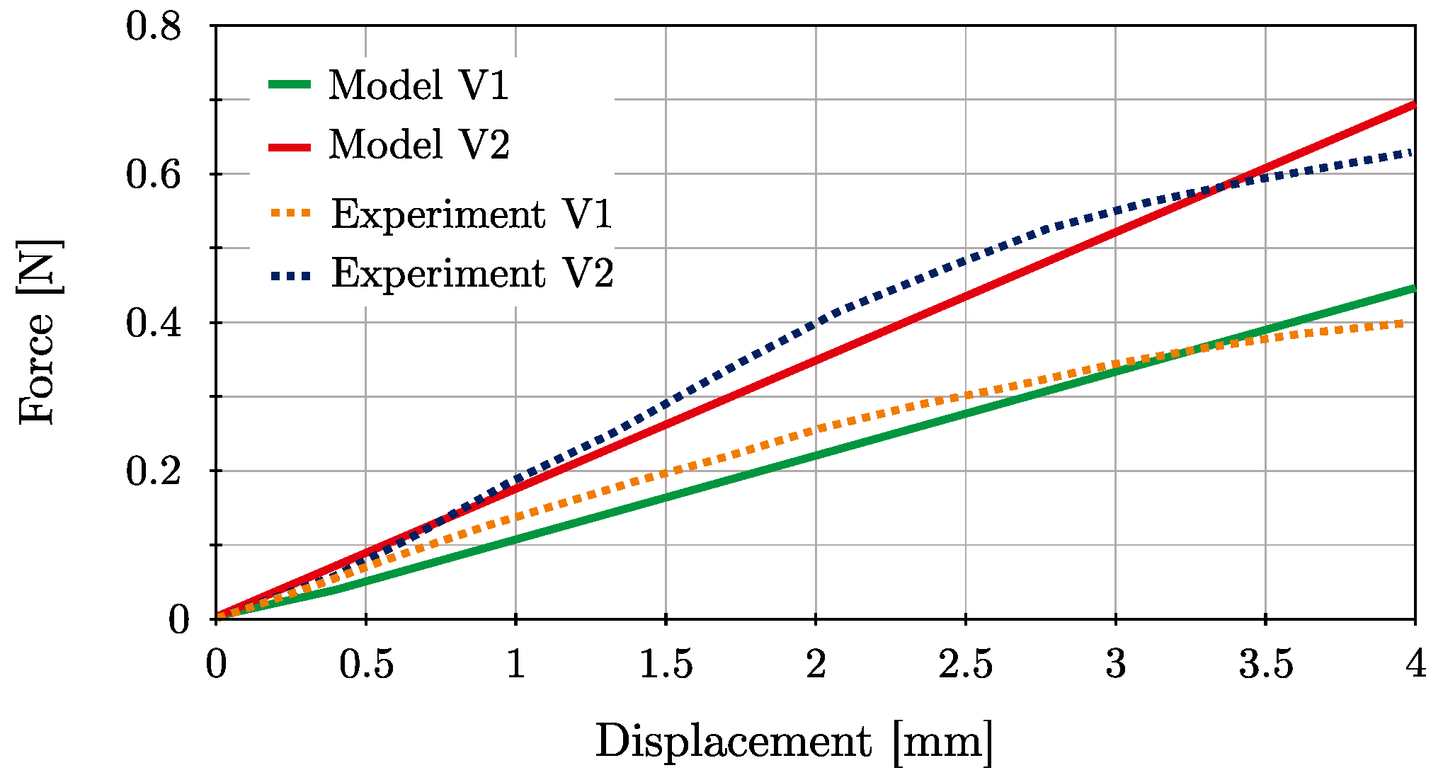
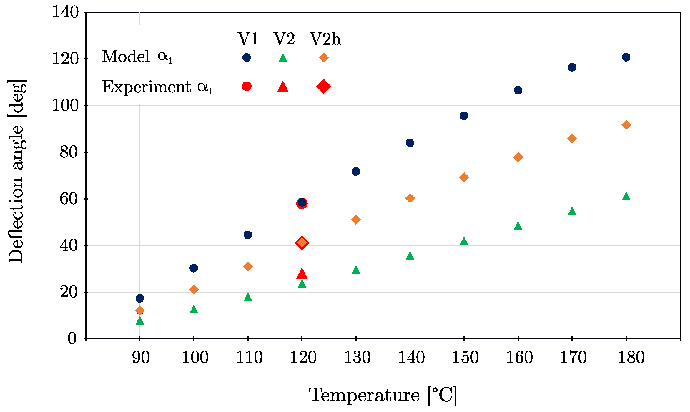
4.3. Results and Discussion

In comparison with the experimental results, the deflection angle α 1 at the activation temperature is shown in Figure 12 in the range from 90 °C to 180 °C. The experimental data agree very well with the calculated result at an activation temperature of 120 °C for all configurations. As shown in Figure 12, the angular difference for α 1 at 120 °C for V1 is only 1% and 0.5% for V2h. Configuration V2 shows a larger deviation of 15.7%. According to the experiments, the deflection angle α over time for multiple cycles is shown in Figure 13. In contrast to the experimental data, all models show a residual angular deflection in form of α 2 after the first heating cycle. This angular deflection α 2 is constant over the entire activation temperature range. For V1, the angular deflection α 2 is 11 deg, for V2, it is 5.1 deg, and for V2h, it is 7.8 deg. In contrast to the experiments, the increase in the angular deflection α 2 for all configurations with the increasing number of cycles is not reflected by the model. In order to capture this effect under cyclic activation, more enhanced material models need to be applied, considering the functional fatigue of the SMA [55] or the viscoelasticity of the polymer.
In the analysis, each configuration shows the lowest angular deflection at the minimum activation temperature of 90 °C, which increases with the increase in the temperature up to the maximum activation temperature of 180 °C, which causes the largest angular deflection. In comparison, configuration V1 shows the largest angular deflection in the form of α 1 for a specific temperature, and configuration V2 shows the smallest, which can be explained by the different bending stiffnesses. The angle α 1 for V1 is on average 2.3 times larger than for V2 and 1.4 times larger than for V2h. The comparison of configurations V2 and V2h clearly shows that a local hinge area improves the bending behaviour towards an increase in the angular tip deflection. The corresponding lateral tip displacements x 1 and z 1 for different activation temperatures are listed in Table 5.
In Figure 12, the increase in the deflection angle α 1 with the increasing activation temperature indicates that the phase transformation from martensite to austenite is incomplete for the considered temperatures up to 180 °C. This is caused by the fact that the phase transformation temperatures increase with the applied load, because more energy is required to deform the crystal structure of the SMA material. The applied Souza–Auricchio material model is able to consider that effect, which is generated by the bending resistance of the specimen during thermal activation of the SMA. The degree of phase transformation can be expressed by the martensite volume fraction φ , which ranges from 0 to 1. Here, a complete phase transformation from martensite to austenite is indicated by φ equal to 1, which is equivalent to the full exploitation of the SMA actuator potential in the form of elongation. No phase transformation is indicated by φ equal to 0. The martensite volume fraction φ is available as an output parameter in ANSYS via EPEQ in NL or NLEPEQ. In Figure 14, the martensite volume fraction φ for all configurations is shown for the considered temperature range. In contrast to the deflection angle α 1 , the martensite volume fraction φ for the activated state decreases for all configurations with decreasing temperature. Configuration V1 shows for all activation temperatures up to 180 °C the smallest martensite volume fraction φ , indicating the highest degree of phase transformation and, therefore, the best exploitation of the actuator potential of all the specimen configurations.
The shape of the deformation for configurations V1, V2, and V2h at specific activation temperatures in the range from 90 °C to 180 °C is shown in Figure 15. It is shown in particular that, with increasing activation temperature, not only does the angular deflection increase, but the deformation shape can also change. This can be seen clearly for configuration V1, where the uniformity of curvature decreases with the increasing activation temperature. In addition, the shapes of V1 with the largest deflection show only a small difference, indicating that the actuator potential of the SMA wire is almost utilised at an activation temperature above 170 °C. This effect can also be observed to a lesser extent in the case of V2h. Configuration V2, on the other hand, shows a uniform curvature for all activation temperatures, whereby a full utilisation of the actuator potential is not noticeable, which is accounted for by the high martensite content that is still present at 180 °C (Figure 14).
In Figure 16, the deformation shape at four different activation temperatures for all configurations is shown in comparison. It can be clearly seen that V1 and V2h reach unevenly curved deformation modes with increasing temperature in contrast to V2.
All models are calculated on a x64 PC with an Intel Core i7-8700K @3.70 GHz CPU and 64 GB RAM by using 4 cores. All models converge successfully for the multi-step analysis with the chosen analysis settings. The corresponding run times of the models for one heating cycle for different activation temperatures are listed in Table 6. With increasing activation temperature, the run times increase as well, which is caused by the resulting higher deflection of the specimen.

5. Conclusions

In this study, a finite element modelling methodology was proposed for analysis and prediction of the bending performance of a PDMS elastomer-based fibre-reinforced composite structure with embedded shape memory alloy wire actuators. Therefore, a multi-layered composite on the basis of a fabric preform with embedded SMA wire actuators, which are realised via knitting technology, was considered. Three specimen configurations with different amounts of fibre reinforcement resulting in different bending stiffnesses were the focus of this work. For adequate modelling, the model parameters for the PDMS, the composite, and the SMA material were derived and validated on the basis of fundamental material characterisation experiments. The strong non-linear hyperelastic material behaviour of the PDMS material was modelled via the third-order Yeoh model. For the bidirectional reinforced GF/PDMS composite material, an isotropic linear elastic behaviour was assumed under bending deformation in only one fibre direction. The thermomechanical behaviour of the SMA was modelled by the well-known Souza–Auricchio model in a temperature range from 23 °C to 180 °C. This material model allowed the representation of the characteristic pseudo-plastic response of the SMA for the martensite state, as well as the pseudo-elastic behaviour for the austenite state. For all the considered specimens with an embedded SMA wire actuator, the modelling methodology showed good agreement with the experiments in terms of the angular deflection at an activation temperature of 120 °C, with a maximum deviation of 19%. Furthermore, the simulation enabled the prediction of the emerging austenite/martensite states during activation and after activation, in addition to the experiments to provide information on the utilisation of the actuator potential. It is shown that for a defined activation temperature, a low specimen stiffness supports the transformation from martensite to austenite during thermal activation and the resulting angular deflection. The model is able to consider the stress-dependent transformation temperatures, where an increase in the specimen stiffness at a defined activation temperature results in a decrease in the angular deflection due to the lower proportion of austenite content. Moreover, the structural realisation of a hinge area with a reduced bending stiffness leads to an increase of up to 50% in the angular deflection. In summary, the proposed simulation method makes a comprehensive contribution to the design of SMA-based adaptive fibre composite structures with locally varying bending stiffnesses in the field of soft robotic applications. In addition, a full parameter set for a commercially available SMA wire actuator with 4.4% pre-stretch, as well as all relevant settings for a implicit analysis, was presented to conduct a robust and efficient analysis in ANSYS. Future studies will include replicate experiments to assess the statistical robustness and thus validate the observed trends and improve the generalizability of the results.

Author Contributions

Conceptualization, H.B.; methodology, H.B.; software, H.B.; validation, H.B.; formal analysis, H.B.; investigation, H.B.; resources, C.C. and M.G.; data curation, H.B.; writing—original draft preparation, H.B.; writing—review and editing, A.H.; visualization, H.B.; supervision, M.G.; project administration, C.C. and M.G.; funding acquisition, M.G. and A.H. All authors have read and agreed to the published version of the manuscript.

Funding

This research was funded by the Deutsche Forschungsgemeinschaft (DFG, German Research Foundation)—450242512.

Data Availability Statement

The datasets used and/or analysed during the current study are available from the corresponding author on reasonable request.

Acknowledgments

The authors would like to thank Felix Lohse, who contributed significantly to the experimental work during his PhD thesis.

Conflicts of Interest

The authors declare that they have no conflicts of interest.

Abbreviations

The following abbreviations are used in this manuscript:
CPUcentral processing unit
DINGerman Institute for Standardisation
DSCdifferential scanning calorimetry
FEAfinite element analysis
GBgigabyte
GFglass fibre
PDMSdimethylpolysiloxane
PTFEpolytetrafluoroethylene
RAMrandom access memory
SEsuperelasticity
SMAshape memory alloy
SMEshape memory effect

References

  1. Intelligence, M. Robotics Market Size & Share Analysis—Growth Trends & Forecasts (2024–2029). Available online: https://www.mordorintelligence.com/industry-reports/soft-robotics-market (accessed on 13 March 2024).
  2. Majidi, C. Soft-Matter Engineering for Soft Robotics. Adv. Mater. Technol. 2019, 4, 1800477. [Google Scholar] [CrossRef]
  3. Laschi, C.; Mazzolai, B.; Cianchetti, M. Soft robotics: Technologies and systems pushing the boundaries of robot abilities. Sci. Robot. 2016, 1, eaah3690. [Google Scholar] [CrossRef]
  4. Case, J.C.; White, E.L.; Kramer, R.K. Soft Material Characterization for Robotic Applications. Soft Robot. 2015, 2, 80–87. [Google Scholar] [CrossRef]
  5. Rodrigue, H.; Wang, W.; Han, M.W.; Kim, T.J.; Ahn, S.H. An overview of shape memory alloy-coupled actuators and robots. Soft Robot. 2017, 4, 3–15. [Google Scholar] [CrossRef]
  6. Jani, J.M.; Leary, M.; Subic, A.; Gibson, M.A. A review of shape memory alloy research, applications and opportunities. Mater. Des. (1980–2015) 2014, 56, 1078–1113. [Google Scholar] [CrossRef]
  7. Sobczyk, M.; Wiesenhütter, S.; Noennig, J.R.; Wallmersperger, T. Smart materials in architecture for actuator and sensor applications: A review. J. Intell. Mater. Syst. Struct. 2022, 33, 379–399. [Google Scholar] [CrossRef]
  8. Sakon, T. (Ed.) Shape Memory Alloys 2017; MDPI AG: Geneva, Switzerland, 2018. [Google Scholar] [CrossRef]
  9. Costanza, G.; Tata, M.E.; Libertini, R. Effect of Temperature on the Mechanical Behaviour of Ni-Ti Shape Memory Sheets. In TMS 2016: 145th Annual Meeting & Exhibition: Supplemental Proceedings; John Wiley & Sons, Inc.: Hoboken, NJ, USA, 2016; pp. 433–439. [Google Scholar] [CrossRef]
  10. Akbari, S.; Sakhaei, A.H.; Panjwani, S.; Kowsari, K.; Serjouei, A.; Ge, Q. Multimaterial 3D Printed Soft Actuators Powered by Shape Memory Alloy Wires. Sensors Actuators A Phys. 2019, 290, 177–189. [Google Scholar] [CrossRef]
  11. Alshebly, Y.S.; Nafea, M.; Mohamed Ali, M.S.; Almurib, H.A. Review on recent advances in 4D printing of shape memory polymers. Eur. Polym. J. 2021, 159, 110708. [Google Scholar] [CrossRef]
  12. Zeng, C.; Liu, L.; Lin, C.; Xin, X.; Liu, Y.; Leng, J. 4D printed continuous fiber reinforced shape memory polymer composites with enhanced mechanical properties and shape memory effects. Compos. Part A Appl. Sci. Manuf. 2024, 180, 108085. [Google Scholar] [CrossRef]
  13. Waidi, Y.O. Recent Advances in 4D-Printed Shape Memory Actuators. Macromol. Rapid Commun. 2025, 46, 2401141. [Google Scholar] [CrossRef]
  14. Kluge, A.; Henneberg, J.; Nocke, A.; Cherif, C. Methods for adhesion/friction reduction of novel wire-shaped actuators, based on shape memory alloys, for use in adaptive fiber-reinforced plastic composites. J. Ind. Text. 2015, 44, 757–768. [Google Scholar] [CrossRef]
  15. Bettini, P.; Riva, M.; Sala, G.; Di Landro, L.; Airoldi, A.; Cucco, J. Carbon Fiber Reinforced Smart Laminates with Embedded SMA Actuators—Part I: Embedding Techniques and Interface Analysis. J. Mater. Eng. Perform. 2009, 18, 664–671. [Google Scholar] [CrossRef]
  16. Mahmood Baitab, D.; Laila Abang Haji Abdul Majid, D.; Junita Abdullah, E.; Faisal Abdul Hamid, M. A review of techniques for embedding shape memory alloy (SMA) wires in smart composites. Int. J. Eng. Technol. 2018, 7, 129–136. [Google Scholar] [CrossRef]
  17. Gapeeva, A.; Vogtmann, J.; Zeller-Plumhoff, B.; Beckmann, F.; Gurka, M.; Carstensen, J.; Adelung, R. Electrochemical Surface Structuring for Strong SMA Wire–Polymer Interface Adhesion. ACS Appl. Mater. Interfaces 2021, 13, 21924–21935. [Google Scholar] [CrossRef]
  18. Cherif, C.; Hickmann, R.; Nocke, A.; Schäfer, M.; Röbenack, K.; Wießner, S.; Gerlach, G. Development and testing of controlled adaptive fiber-reinforced elastomer composites. Text. Res. J. 2018, 88, 345–353. [Google Scholar] [CrossRef]
  19. Ren, Z.; Zarepoor, M.; Huang, X.; Sabelhaus, A.P.; Majidi, C. Shape Memory Alloy (SMA) Actuator With Embedded Liquid Metal Curvature Sensor for Closed-Loop Control. Front. Robot. AI 2021, 8, 599650. [Google Scholar] [CrossRef]
  20. Acevedo-Velazquez, A.I.; Wang, Z.; Winkler, A.; Modler, N.; Röbenack, K. Manufacture and Deformation Angle Control of a Two-Direction Soft Actuator Integrated with SMAs. Materials 2024, 17, 758. [Google Scholar] [CrossRef]
  21. Yu, Y.; Fu, T. Design and Experimental Study of Cavity Structure of Pneumatic Soft Actuator. Actuators 2023, 12, 314. [Google Scholar] [CrossRef]
  22. Annadata, A.R.; Acevedo-Velazquez, A.I.; Woodworth, L.A.; Gereke, T.; Kaliske, M.; Röbenack, K.; Cherif, C. Investigation and Validation of a Shape Memory Alloy Material Model Using Interactive Fibre Rubber Composites. Materials 2024, 17, 1163. [Google Scholar] [CrossRef]
  23. Rodinò, S.; Maletta, C. Multiphysics modeling and optimization of an innovative shape memory alloy-polymer active composite. Polymer 2024, 307, 127316. [Google Scholar] [CrossRef]
  24. Tuyboyov, O.V.; Lee, G.S.; Lee, G.Y. Multi-mode Soft Composite Bending Actuators Based on Glass fiber Textiles Interwoven with Shape Memory Alloy Wires: Development and use in the Preparation of Soft Grippers. Int. J. Precis. Eng. Manuf.-Green Technol. 2023, 10, 1263–1280. [Google Scholar] [CrossRef]
  25. Lee, J.; Chung, Y.S.; Rodrigue, H. Long Shape Memory Alloy Tendon-based Soft Robotic Actuators and Implementation as a Soft Gripper. Sci. Rep. 2019, 9, 11251. [Google Scholar] [CrossRef] [PubMed]
  26. Lalegani Dezaki, M.; Bodaghi, M.; Serjouei, A.; Afazov, S.; Zolfagharian, A. Adaptive reversible composite-based shape memory alloy soft actuators. Sensors Actuators A Phys. 2022, 345, 113779. [Google Scholar] [CrossRef]
  27. Pietsch, M.; Henkel, K.; Körbitz, R.; Hüttner, R.; Uhlig, K.; Bruk, S.; Fischer, M.; Hampe, J.; Richter, A.; Brinkmann, F. A deflectable video camera system for laparoscopic surgery based on shape memory alloy actuators. Sci. Rep. 2025, 15, 11354. [Google Scholar] [CrossRef]
  28. Wollmann, J.; Muschalski, L.; Wang, Z.; Zichner, M.; Winkler, A.; Modler, N. Application of genetic algorithm for the synthesis of path-generating compliant mechanisms. Smart Mater. Struct. 2023, 33, 015023. [Google Scholar] [CrossRef]
  29. Coyle, S.; Majidi, C.; LeDuc, P.; Hsia, K.J. Bio-inspired soft robotics: Material selection, actuation, and design. Extrem. Mech. Lett. 2018, 22, 51–59. [Google Scholar] [CrossRef]
  30. Beter, J.; Schrittesser, B.; Lechner, B.; Mansouri, M.R.; Marano, C.; Fuchs, P.F.; Pinter, G. Viscoelastic Behavior of Glass-Fiber-Reinforced Silicone Composites Exposed to Cyclic Loading. Polymers 2020, 12, 1862. [Google Scholar] [CrossRef]
  31. Xiang, Y.; Zhong, D.; Rudykh, S.; Zhou, H.; Qu, S.; Yang, W. A Review of Physically Based and Thermodynamically Based Constitutive Models for Soft Materials. J. Appl. Mech. 2020, 87, 110801. [Google Scholar] [CrossRef]
  32. Whitney, J.M. Basic Mechanics of Fiber Reinforced Composite Materials. Text. Res. J. 1967, 37, 1056–1062. [Google Scholar] [CrossRef]
  33. Brinson, L. One-Dimensional Constitutive Behavior of Shape Memory Alloys: Thermomechanical Derivation with Non-Constant Material Functions and Redefined Martensite Internal Variable. J. Intell. Mater. Syst. Struct. 1993, 4, 229–242. [Google Scholar] [CrossRef]
  34. Lagoudas, D.; Hartl, D.; Chemisky, Y.; Machado, L.; Popov, P. Constitutive model for the numerical analysis of phase transformation in polycrystalline shape memory alloys. Int. J. Plast. 2012, 32–33, 155–183. [Google Scholar] [CrossRef]
  35. Auricchio, F.; Sacco, E. A one-dimensional model for superelastic shape-memory alloys with different elastic properties between austenite and martensite. Int. J. Non-Linear Mech. 1997, 32, 1101–1114. [Google Scholar] [CrossRef]
  36. He, B.; Dong, X.; Nie, R.; Wang, Y.; Ao, S.; Wang, G. Comprehensive shape memory alloys constitutive models for engineering application. Mater. Des. 2023, 225, 111563. [Google Scholar] [CrossRef]
  37. Woodworth, L.A.; Wang, X.; Lin, G.; Kaliske, M. A multi-featured shape memory alloy constitutive model incorporating tension–compression asymmetric interpolation. Mech. Mater. 2022, 172, 104392. [Google Scholar] [CrossRef]
  38. Turner, T.L. A New Thermoelastic Model for Analysis of Shape Memory Alloy Hybrid Composites. J. Intell. Mater. Syst. Struct. 2000, 11, 382–394. [Google Scholar] [CrossRef]
  39. Pan, J.; Yu, J.; Li, G.; Wu, H.; Pei, X. A lightweight bending actuator based on shape memory alloy and application to gripper. Mech. Adv. Mater. Struct. 2023, 30, 4372–4382. [Google Scholar] [CrossRef]
  40. Böhm, H.; Winkler, A.; Senf, B.; Voigt, I.; Drossel, W.G.; Gude, M. Experimental and numerical analysis of bending performance for a glass-epoxy composite with integrated sheet-shaped shape memory alloy actuator elements. Mech. Adv. Mater. Struct. 2025, 32, 391–402. [Google Scholar] [CrossRef]
  41. Airoldi, A.; Rigamonti, D.; Sala, G.; Bettini, P.; Villa, E.; Nespoli, A. Development of an actuated corrugated laminate for morphing structures. Aeronaut. J. 2021, 125, 180–204. [Google Scholar] [CrossRef]
  42. Böhm, H.; Schmidt, A.; Kopelmann, K.; Hornig, A.; Cherif, C.; Gude, M. Thermomechanical characterisation of a shape memory alloy for numerical modeling of its actuation response. Mater. Res. Express 2024, 11, 125701. [Google Scholar] [CrossRef]
  43. Moučka, R.; Sedlačík, M.; Osička, J.; Pata, V. Mechanical properties of bulk Sylgard 184 and its extension with silicone oil. Sci. Rep. 2021, 11, 19090. [Google Scholar] [CrossRef]
  44. Lohse, F.; Kopelmann, K.; Grellmann, H.; Ashir, M.; Gereke, T.; Häntzsche, E.; Sennewald, C.; Cherif, C. Experimental and numerical analysis of the deformation behavior of adaptive fiber-rubber composites with integrated shape memory alloys. Materials 2022, 15, 582. [Google Scholar] [CrossRef]
  45. Lohse, F.; Annadata, A.R.; Häntzsche, E.; Gereke, T.; Trümper, W.; Cherif, C. Hinged Adaptive Fiber-Rubber Composites Driven by Shape Memory Alloys - Development and Simulation. Materials 2022, 15, 3830. [Google Scholar] [CrossRef]
  46. Endesfelder, A.; Annadata, A.R.; Acevedo-Velazquez, A.I.; Koenigsdorff, M.; Gerlach, G.; Röbenack, K.; Cherif, C.; Zimmermann, M. Deflection and Performance Analysis of Shape Memory Alloy-Driven Fiber–Elastomer Composites with Anisotropic Structure. Materials 2024, 17, 4855. [Google Scholar] [CrossRef]
  47. Lohse, F.M. Numerische Auslegung und Entwicklung von adaptiven Strukturen auf Basis von Formgedächtnislegierungen am Beispiel textilverstärkter Elastomerkomposite. Ph.D. Thesis, TUD Dresden University of Technology, Dresden, Germany, 2022. [Google Scholar]
  48. Souza, A.C.; Mamiya, E.N.; Zouain, N. Three-dimensional model for solids undergoing stress-induced phase transformations. Eur. J. Mech.-A/Solids 1998, 17, 789–806. [Google Scholar] [CrossRef]
  49. Auricchio, F.; Petrini, L. Improvements and algorithmical considerations on a recent three-dimensional model describing stress-induced solid phase transformations. Int. J. Numer. Methods Eng. 2002, 55, 1255–1284. [Google Scholar] [CrossRef]
  50. Auricchio, F.; Petrini, L. A three dimensional model describing stress temperature induced solid phase transformations: Solution algorithm and boundary value problems. Int. J. Numer. Methods Eng. 2004, 61, 807–836. [Google Scholar] [CrossRef]
  51. Auricchio, F.; Petrini, L. A three dimensional model describing stress temperature induced solid phase transformations: Thermomechanical coupling and hybrid composite applications. Int. J. Numer. Methods Eng. 2004, 61, 716–737. [Google Scholar] [CrossRef]
  52. Grassi, E.N.D.; Chagnon, G.; de Oliveira, H.M.R.; Favier, D. Anisotropy and Clausius-Clapeyron relation for forward and reverse stress-induced martensitic transformations in polycrystalline NiTi thin walled tubes. Mech. Mater. 2020, 146, 103392. [Google Scholar] [CrossRef]
  53. Yeoh, O.H. Some Forms of the Strain Energy Function for Rubber. Rubber Chem. Technol. 1993, 66, 754–771. [Google Scholar] [CrossRef]
  54. ANSYS® Enterprise Mechanical, 2023 R1, Help System, Mechanical APDL Material Reference, 4.15 Shape Memory Alloy (SMA). ANSYS, Inc.: Canonsburg, PA, USA, 2023.
  55. Woodworth, L.A.; Kaliske, M. A temperature dependent constitutive model for functional fatigue in shape memory alloys. Mech. Mater. 2022, 165, 104126. [Google Scholar] [CrossRef]
Figure 1. Schematic illustration of preform V1 with embedded SMA wire material (left) and full specimen (right).
Jcs 09 00371 g001
Figure 2. Textile preform concept for specimen configurations.
Jcs 09 00371 g002
Figure 5. Deflection angle during cyclic activation and de-activation.
Jcs 09 00371 g005
Figure 6. Exemplary stress–strain curves for shape memory alloy.
Jcs 09 00371 g006
Figure 7. Comparison of the experimental and analysis tensile test data.
Jcs 09 00371 g007
Figure 8. Comparison of the experimental tensile test data with Yeoh material model for the PDMS used.
Jcs 09 00371 g008
Figure 9. Comparison of the experimental four-point bending test data with the analysis.
Jcs 09 00371 g009
Figure 10. Loading conditions for multi-step analysis.
Jcs 09 00371 g010
Figure 11. Finite element model with detailed views (for configuration V1).
Jcs 09 00371 g011
Figure 12. Angular deflection angle α 1 for a single activation cycle.
Jcs 09 00371 g012
Figure 13. Angular tip deflection over time for multiple activation cycles.
Jcs 09 00371 g013
Figure 14. Martensite volume fraction at maximum deflection in activated state.
Jcs 09 00371 g014
Figure 15. Shape of deformation at specific temperatures in the range from 90 °C to 180 °C.
Jcs 09 00371 g015
Figure 16. Comparison of deformation shapes at specific activation temperatures.
Jcs 09 00371 g016
Table 1. Phase transformation temperatures for NiTi SMA wire material.
TemperatureSymbolUnitValue
Martensite Finish M f °C30
Martensite Start M s °C50
Austenite Start A s °C67
Austenite Finish A f °C77
Table 2. Model parameters for NiTi SMA wire material.
PropertyParameterUnit23 °C60 °C90 °C130 °C
Elastic modulusEN/mm235,00035,00070,00070,000
Poisson’s ratio ν -0.30.30.30.3
Elastic modulus (Martensite) E M N/mm221,65021,65021,65021,650
Hardening parameterhMPa6006008001000
Reference temperature T 0 °C23606060
Temperature scaling β MPa/K7.27.27.27.2
Elastic stress limitRMPa60120120120
Max. transformation strain ε ¯ L %4.04.04.04.0
Lode parameterm-0000
Table 3. Third-order Yeoh model parameter for PDMS material.
ParameterUnitValue
C10N/mm20.2204960
C20N/mm2−0.0339723
C30N/mm20.0422553
Table 4. Elastic modulus for GF/PDMS composite material.
ConfigurationParameterUnitValue
V1EN/mm2450
V2EN/mm2700
Table 5. Displacements and deflection angles for different activation temperatures.
V1V2V2h
T z 1 x 1 α 1 z 1 x 1 α 1 z 1 x 1 α 1
°Cmmdegmmdegmmdeg
9013.71.717.36.20.47.89.71.012.2
10023.74.730.310.11.012.716.62,521.1
11034.09.844.514.21.817.924.25.231.0
12043.216.258.518.63.023.631.59.041.2
13050.623.471.723.24.629.639.813.351.1
14056.430.983.927.86.535.743.818.260.4
15060.838.595.632.48.842.048.623.269.3
16064.046.0106.636.811.548.552.728.577.9
17065.952.8116.441.114.554.956.033.886.0
18066.655.9120.745.017.861.358.137.591.7
Table 6. Analysis run times for one cycle.
90 °C120 °C150 °C180 °C
V1170 s597 s861 s1090 s
V2172 s373 s485 s727 s
V2h340 s732 s859 s1689 s
Disclaimer/Publisher’s Note: The statements, opinions and data contained in all publications are solely those of the individual author(s) and contributor(s) and not of MDPI and/or the editor(s). MDPI and/or the editor(s) disclaim responsibility for any injury to people or property resulting from any ideas, methods, instructions or products referred to in the content.

