1. Introduction
Medical phantoms are essential tools in both healthcare and research, designed to replicate the physical and mechanical properties of human tissues. They serve multiple purposes, including imaging calibration, clinician training, surgical planning, and the development of new technologies. By providing standardized reference materials, phantoms help ensure consistent and accurate imaging across different equipment and clinical settings [
1,
2,
3]. In addition to offering a safe, risk-free environment for medical training [
4,
5,
6], they enable cost-effective testing and validation without the need for human subjects [
7,
8,
9]. These materials support preoperative planning [
10] and play a critical role in the evaluation of multimodal imaging techniques. Recent advancements in materials (such as polymer gels, UV-curable silicones, and other synthetic soft-tissue analogues) have significantly improved phantom realism, thereby enhancing the reliability of imaging in both clinical and research applications [
11,
12]. In the field of medical acoustics, ultrasound phantoms are particularly important. They are used to assess and calibrate imaging systems by evaluating spatial resolution, contrast, and penetration depth for ultrasound and elastography equipment [
13]. Phantoms also enable the simulation of blood flow dynamics, which is crucial to Doppler ultrasound studies. High-fidelity ultrasound phantoms provide a safe and realistic setting for practicing ultrasound-guided procedures such as vascular access or biopsies [
6,
14,
15], while tissue-mimicking models are used in research areas like focused ultrasound therapies and tumor ablation [
16,
17]. They also help validate advanced techniques, including pulse wave imaging [
18] and ultrasound stimulation [
19,
20], and contribute to standardizing diagnostic protocols across different ultrasound platforms [
21]. As material science and 3D-printing technologies continue to evolve, ultrasound phantoms are becoming increasingly sophisticated, enabling more accurate imaging, safer interventions, and improved patient outcomes.
While ultrasound phantoms replicate the acoustic properties of soft tissues, they often fall short in replicating the complex mechanical properties of soft fibrous tissues. Biological materials exhibit complex mechanical behaviors like viscoelasticity [
22,
23] and anisotropy [
23,
24], which are difficult to reproduce with the commonly used materials for acoustic medical phantoms such as gelatine and agarose [
25,
26]. Unlike typical solid materials, the acoustic behavior of soft fibrous tissues depends not only on their solid matrix mechanical properties but also on the fluid they contain. While shear waves propagate only through the solid phase, compressive waves travel significantly faster through the fluid phase, making both essential to accurate modeling [
27,
28]. Balancing mechanical and acoustic fidelity is challenging, often resulting in phantoms optimized for one property at the expense of the other [
29,
30]. Additionally, maintaining stable mechanical properties over time is another challenge, since the typically used materials may degrade or change properties, affecting the accuracy of the phantom over extensive time periods [
31].
Recent advances in elastography have underscored the growing need for reproducible, anisotropic tissue-mimicking phantoms that enable the precise calibration and validation of imaging modalities such as magnetic resonance elastography (MRE) and ultrasound-based shear wave elasticity imaging (SWEI). Yoon et al. (2023) demonstrated that structural anisotropy can be effectively introduced into hydrogel phantoms using scaled 3D-printed lattice architectures, yielding directional mechanical properties that closely mimic those found in fibrous biological tissues [
32]. Building upon this approach, Srinivasan et al. (2025) validated the compatibility of such anisotropic lattices with advanced SWEI techniques, highlighting their suitability for multimodal characterization and cross-validation [
33]. Together, these studies provide a robust framework for designing tunable, anisotropic phantoms that are mechanically relevant, scalable, and compatible with existing imaging infrastructures.
Several studies have attempted to replicate the anisotropic properties of soft biological tissues in phantom design, but a universally effective solution remains elusive. For example, Guidetti et al. developed 3D-printed phantoms by embedding crosslinked gelatine fibers within a softer gelatine matrix, forming a grid-like structure that exhibited orthotropic mechanical behavior. These phantoms demonstrated realistic anisotropic shear modulus across orthogonal planes, with tunable viscoelastic properties dependent on fiber density and matrix stiffness, effectively mimicking skeletal muscle and enhancing magnetic resonance elastography (MRE) calibration [
34]. Similarly, Eckstein et al. designed phantoms using directionally scaled PEGDA lattices embedded in gelatine, creating composites with quantifiable shear and tensile anisotropy. Their phantoms produced anisotropic wavefields, and the use of a transversely isotropic nonlinear inversion algorithm validated the accuracy of MRE in detecting spatial variations in mechanical properties [
35]. Suzuki et al. investigated wood and synthetic fibers as low-cost, naturally anisotropic materials for diffusion Magnetic Resonance Imaging Phantoms. Their results demonstrated stable diffusion metrics over nine months, with anisotropy being influenced by sample orientation, supporting wood’s potential as an accessible phantom material [
36]. Berberat et al. emphasized the need for quality assurance in diffusion-weighed MRI, showing that while fractional anisotropy values were consistent across software platforms, most tools struggled to represent complex fiber crossings accurately. They recommend the cautious interpretation of fiber tracking data in clinical settings [
37]. In contrast, recent efforts in ultrasound phantom development have prioritized anatomical realism through 3D printing [
38], the integration of flow dynamics [
39], and AI-based quantification [
40]. However, these approaches largely overlook anisotropy, leaving a critical gap in tactile realism, which is essential to clinician training and the development of therapeutic ultrasound applications that rely on directional mechanical properties.
Despite their importance, many of these materials for ultrasound phantoms remain costly, short-lived, and environmentally unsustainable, barriers that hinder widespread adoption, especially in low-resource settings. High-fidelity commercial models, such as those used for trauma simulation or vascular access training, offer excellent anatomical realism but are often prohibitively expensive due to the use of advanced manufacturing technologies like high-resolution 3D printing and custom molds. These models require precise materials and intricate designs, further driving up costs [
41]. Even specialized musculoskeletal phantoms made with 3D-printed molds face challenges, not only in affordability but also in realistically replicating complex tissue mechanics [
42]. Popular commercial options like Blue Phantom provide consistent and realistic feedback for procedures such as ultrasound-guided vein cannulation, yet they remain financially inaccessible to many clinics, universities, and training centers. The need for multiple units in training environments only amplifies the economic burden [
43]. Low-cost alternatives, such as phantoms made from gelatine–agar mixtures, offer initial affordability but degrade rapidly with use, particularly under repeated needle insertions or exposure to fluctuating environmental conditions. Their short lifespan leads to high maintenance demands, increased material waste, and hidden recurring costs that can rival those of more expensive models over time [
44].
Sustainability is another pressing issue. Many commercial phantoms are made from synthetic rubbers or plastics that are non-biodegradable and contribute to long-term environmental waste [
45]. As the adoption of 3D printing grows, the use of non-recyclable polymers for phantom production risks further exacerbating plastic pollution. Although promising research into biodegradable materials like polyvinyl alcohol (PVA) and alginate has emerged, these options are not yet widely implemented in practice [
46]. As such, there is a growing need for ultrasound phantoms that are not only anatomically and mechanically realistic but also sustainable, affordable, and durable, avoiding forcing institutions to choose among performance, cost, and eco-conscience.
This article introduces a novel class of sustainable, low-cost anisotropic phantoms that aim to simulate both the dynamic mechanical properties and ultrasound behaviors inherent in fibrous biological tissues such as skin and skeletal muscle. By integrating renewable natural fibers within a biological elastomeric silicone matrix, these medical phantoms offer tunable properties suited for both clinical imaging and therapeutic applications. In addition to performance, this approach aligns with sustainability goals by reducing material costs and environmental impact, thus bridging the gap among realism, affordability, and eco-conscious innovation.
2. Materials and Methods
To design composite medical phantoms that reliably replicate the anisotropic mechanical and acoustic behavior of fibrous biological tissues, this investigation follows a tightly integrated methodological framework that bridges theoretical modeling and experimental validation. The logic underpinning this study rests on a bidirectional design loop: computational simulations were used to guide material selection, structural formulation, and expected tissue-mimicking performance, while experimental tests were conducted to validate these predictions and refine model assumptions. First, the mechanical response of the silicone matrix was characterized and fitted to hyperelastic constitutive models, forming the basis for simulating tissue-like behavior under physiological loads. This modeling informed the composite design by enabling control over anisotropy through fiber orientation and volume fraction. These structural features were then implemented in a custom fabrication process, ensuring physical reproducibility. Parallel to mechanical characterization, both viscoelastic and acoustic wave propagation simulations were conducted to anticipate the frequency-dependent and directional responses of the phantoms, thereby informing design targets for elastography and ultrasound validation. The manufacturing method and experimental testing were carefully planned to mirror the computational setups, ensuring consistency across scales. This systematic approach ensures that each theoretical assumption and computational prediction is grounded in and iteratively refined by experimental evidence, yielding phantoms that are bioinspired and validated.
2.1. Computational Methods
In order to establish meaningful benchmarks and guide the design of the composite phantom materials, computational modeling was employed at three critical stages of this study. All simulations were conducted using COMSOL Multiphysics 5.3, while Python 3.13.2 was used for data processing and analysis. First, simulations were performed to replicate the mechanical and dynamic behavior of biological tissues under the same testing conditions used for the phantoms, enabling direct comparison and validation. Second, mechanical modeling was used to characterize the elastomeric matrix by fitting its experimentally obtained mechanical response to suitable hyperelastic constitutive models. Finally, computational tools were applied to iteratively refine the formulation of the phantom material by adjusting fiber content to achieve the desired acoustic and mechanical anisotropy that mimics the target tissues.
2.1.1. Tensile Hyperelastic Model Curve Fitting
The mechanical behavior of the elastomeric matrix was characterized using uniaxial tensile test data, which were then fitted to multiple hyperelastic material models through the Cauchy stress formulation. Estimating material parameters for hyperelastic models, particularly when accounting for volumetric deformation, can be a complex task. To simplify this, the material is often assumed to be perfectly incompressible, a valid approximation for most rubbers and elastomers. Under the assumption of near-incompressibility, the strain energy density function is typically separated into two components: the isochoric part
, which accounts for shape change, and the volumetric part
which accounts for volume change.
is the Lagrange Multiplier. For incompressible materials,
, as described in Equation (1).
Accordingly, the second Piola–Kirchhoff stress tensor is defined in Equation (2), where
represents the volume ratio and
denotes the right Cauchy–Green deformation tensor.
Expanding Equation (2) to explicitly express the second Piola–Kirchhoff stress leads to Equation (3), where
and
are invariants of the isochoric Cauchy–Green stress
.
The first Piola–Kirchhoff stress tensor
and the Cauchy stress tensor
can both be expressed in terms of the second Piola–Kirchhoff stress tensor
, using the deformation gradient
. This relationship is given by Equation (4).
In hyperelastic formulations, both the strain energy density and associated stress tensors are often expressed in terms of the stretch ratio
, which quantifies the degree of deformation. In a uniaxial tensile test, the stretch ratio is defined as
, where
is the deformed length and
is the original (undeformed) length. In the case of a multiaxial stress state, the principal stretches
can be computed in the principal directions
, which align with the directions of the principal stresses. The right Cauchy–Green deformation tensor
in its spectral form is demonstrated in Equation (5).
Under the assumption of incompressibility (
), the principal stretches for the uniaxial extension of an isotropic hyperelastic material are given by Equation (6).
The corresponding deformation gradient
becomes Equation (7).
For uniaxial extension, assuming
, the pressure
can be eliminated from the formulation. This leads to the expression for the first Piola–Kirchhoff stress
, derived from the second Piola–Kirchhoff stress
as given by Equation (8).
Here,
and
are the isochoric strain invariants in uniaxial deformation, defined in terms of the stretch ratio
, as shown in Equation (9).
To identify a suitable constitutive model for the biological silicone, the experimental data were fitted to four different hyperelastic material models: the Neo-Hookean model, the two-parameter Mooney–Rivlin model, the five-parameter Mooney–Rivlin model, and the Ogden model.
The isochoric strain energy density for an incompressible Neo-Hookean material is defined in Equation (10), where
is the material parameter to be determined through the curve fitting of the experimental data.
Assuming perfect incompressibility and applying Equation (8), the expression for the first Piola–Kirchhoff stress under uniaxial deformation for the Neo-Hookean model simplifies to Equation (11).
Seemingly, the two-parameter Mooney–Rivlin model expresses the uniaxial first Piola–Kirchhoff stress as in Equation (12).
The five-parameter Mooney–Rivlin model incorporates higher-order terms involving the isochoric invariants
and
and is given by Equation (13).
The Ogden model captures nonlinear elastic behavior using a spectral representation based on principal stretches. For uniaxial deformation, the first Piola–Kirchhoff stress is given by Equation (14).
To determine the optimal material parameters for each constitutive model, the least squares method was employed. This approach minimizes the sum of the squared differences between the experimentally measured stresses and the model-predicted stresses over the full range of stretch ratios. By fitting each model to the experimental uniaxial tensile data, the method identifies the parameter set that best captures the material’s nonlinear response. The resulting optimal parameters for each model are presented and compared in the Results Section.
The tensile test was simulated under conditions replicating the experimental setup using the solid mechanics physics interface, in the structural mechanics module, including the nonlinear structural materials module. A sample with dimensions of 120 mm in length, 20 mm in width, and 2 mm in thickness was modeled. To replicate the grip configuration, the geometry was divided into two regions: 40 mm from the base and 40 mm from the top, corresponding to the grip locations. The bottom section was fixed, while the top was subjected to a prescribed displacement at a constant velocity of 10 mm/min, matching the experimental test speed. The time values recorded during the physical tensile test were used to define the duration of the simulation. A cross-sectional plane was placed at the center of the sample to extract the average Cauchy stress, which was then compared with the experimental data. A mesh convergence analysis was performed, and a triangular mesh with a 1 mm element size was selected as optimal for accurate and stable results.
2.1.2. Micro- and Macromechanical Composite Formulation
In many cases, the microscale heterogeneity of a material makes it impractical to use detailed local properties directly in macroscopic structural analyses. Instead, a homogenized material model with appropriately averaged effective properties is typically employed. COMSOL Multiphysics uses its cell periodicity feature, which is built on the concept of a Representative Volume Element, which is referred to as the Repeating Unit Cell (RUC) method. The RUC defines a domain that captures the essential microstructural characteristics of the material. When dealing with a periodic microstructure composed of repeated unit cells, the displacement field across the domain can be expressed using Equation (15), where
is the global average strain tensor and
is a function that is periodic from one unit cell to another.
Since the array of unit cells forms a continuous structure, displacement continuity must be maintained across adjacent cell boundaries. In COMSOL, this is implemented using the Boundary Pair subnode, which requires each boundary to be defined in parallel pairs: one designated as the source and the other as the destination. The displacement field across these opposing, parallel surfaces must satisfy periodic continuity conditions, which can be mathematically expressed as shown in Equation (16).
Thus, displacement continuity is enforced through the condition described in Equation (17).
The material parameters used in the composite simulations were assigned separately for the fiber and the elastomeric matrix phases. The properties of the elastomeric matrix were obtained through the curve fitting of the experimental data, as detailed in the previous section. In contrast, the fiber properties were determined directly from experimental testing. The full set of parameters used is presented in
Table 1.
With the microscale structure established, the next step involves transferring its behavior to the macroscale domain. This is achieved by applying six independent load cases to compute the effective elasticity matrix. The homogenization approach enables the conversion of the heterogeneous unit cell into an equivalent continuous medium. The macroscopic stress (
) and strain tensors (
) are obtained by averaging the corresponding microscopic fields over the volume of the periodic cell (
), as expressed in Equation (18).
Based on the homogenization process, the effective macroscopic elasticity tensor is defined as shown in Equation (19).
To guide the design of the phantom material, the simulated mechanical response of each composite formulation was compared with constitutive models of biological tissues reported in the literature, using the solid mechanics physics interface, in the structural mechanics module, including the composite materials module. By fitting the composite behavior to these target models, the optimal formulation was identified based on its ability to replicate the mechanical characteristics of native fibrous tissues.
2.1.3. Dynamic Mechanical Response Calculation
To simulate the dynamic behavior of fibrous tissues, specifically human skin and skeletal muscle, a dynamic compressive mechanical test was implemented in COMSOL Multiphysics, using the solid mechanics physics interface, in the structural mechanics module. This simulation incorporated a formulation accounting for viscoelastic energy absorption, a key characteristic of these tissues. A 20 mm × 20 mm × 2 mm specimen was modeled, with one end fixed while a sinusoidal load was applied to the other. The study focused on analyzing the loss and storage moduli across a frequency range of 10 to 100 Hz, providing insights into the material’s frequency-dependent mechanical response, utilizing the Finite Element Method.
The viscoelastic behavior of the simulated fibrous tissues was modeled using the Kelvin–Voigt material formulation, a widely used approach for the dynamic characterization of biological materials. This model is particularly suitable for biological tissues, as it effectively describes their ability to absorb and gradually release mechanical energy under cyclic loading, closely mirroring the behavior observed in soft tissues like skin and muscle. The Kelvin–Voigt model represents tissue mechanics through a parallel combination of an elastic spring (
), which accounts for the immediate elastic response, and a viscous damper (
), which captures the time-dependent energy dissipation, represented in Equation (20).
All the necessary parameters for this simulation are presented in
Table 2, including material properties and model coefficients used in the Kelvin–Voigt formulation. Instead of using a single value for each parameter, a range of values was implemented to account for the heterogeneity of biological tissues. To capture this variability, several parametric sweeps were performed, allowing for the identification of an ideal range of expected values that best represent the dynamic behavior of fibrous tissues.
The outcomes measured in this simulation were the storage modulus, the loss modulus, and the complex modulus across the chosen frequency range. The storage modulus represents the elastic, energy-storing component of the material’s response, while the loss modulus quantifies the viscous, energy-dissipating behavior. By analyzing these parameters over the selected frequency range, the simulation provided insights into the frequency-dependent viscoelastic properties of the modeled biological tissues. Model convergence was checked to ensure the solution was precise.
2.1.4. Acoustic Wave Propagation Calculation
In order to simulate the acoustic wave propagation in COMSOL Multiphysics, a time-explicit wave propagation method was used, using the solid mechanics physics interface, in the structural mechanics module and the acoustics module. In it, wave propagation is simulated using the discontinuous Galerkin Finite Element Method to solve the acoustic wave equation given by Equation (21), where
is the density,
is the pressure, and
is time.
The phantom sample was modeled using the time-explicit elastic wave method, based on the tensile properties of the equivalent composite. This approach solves the governing equations for a general linear elastic material using a velocity–strain formulation (Equation (22)). In this model, v represents the particle velocity, ρ is material density, S is the stress tensor, E the strain tensor,
is the stiffness tensor, and
denotes any applied body forces.
The transducers were also modeled using the time-explicit elastic wave module, except for the PZT disc, which was simulated using the piezoelectric time-explicit and static electricity Multiphysics interface.
To ensure simulation accuracy, the Courant–Friedrichs–Lewy (CFL) condition was applied by sizing the mesh to provide at least 1.5 elements per wavelength when using quartic elements, as outlined in Equation (23). Accordingly, the maximum mesh element size (
) was determined using a CFL-based expression, where
is the minimum wavelength.
is the maximum frequency, and
is the minimum wave speed in the model.
An axisymmetric simulation setup was used to model both the transducer and the phantom sample, which had dimensions of 2 mm in thickness and 40 mm in width. A single pulse was emitted from the transducer, and two observation nodes were placed within the solid: one in the longitudinal direction and the other in the transverse direction. This allowed for the measurement of longitudinal wave speed (LWS) and shear wave speed (SWS), respectively. LWS values are intended for validation using ultrasound measurements, while SWS values are to be compared with elastography results. Attenuation effects were not included in the simulation, as the necessary parameters could not be determined prior to conducting experimental measurements. For this reason, simulations were solved only at 500 kHz, since attenuation was not computed and wave velocity is independent of frequency in elastic media.
2.2. Manufacturing Method
The samples were fabricated using a biocompatible silicone elastomer (SG587, EcoArte, Porto, Portugal; with an approximate Shore A hardness of 30), mixed in a 1:1 ratio of base to curing agent, as per the manufacturer’s specifications. Both components were weighed using a high-precision milligram scale to ensure accurate proportions and consistent mixing. A mechanical homogenizer was then used to thoroughly blend the components and achieve a uniform mixture.
Natural fibers from Cordyline australis were used as reinforcement. The fibers were also weighed using the same precision scale to maintain a controlled and consistent fiber-to-matrix ratio, with fiber diameters ranging from 48 μm to 184 μm. Each fiber was prepared by manual brushing to remove loose debris and improve alignment. Being a long-fiber composite, each fiber spanned the full length of the final sample. The fibers were then carefully arranged within the mold according to the desired orientation, which matched the primary fiber direction of the biological tissue being mimicked (e.g., along the axis of skin, skeletal muscle, or other fibrous tissues).
The silicone mixture was slowly poured into the mold, fully encapsulating the fibers while avoiding fiber displacement. To minimize voids and trapped air, the filled mold was placed in a vacuum chamber (ultimate vacuum of 0.8 Pa) for 20 min for degassing.
The mold used in this study was custom-designed and 3D-printed to allow for adjustable height, enabling the fabrication of multilayered samples. After degassing, the sample was compressed under a load of 3 kPa for 3 h at room temperature to ensure fiber integration and matrix consolidation. If additional layers were required, the same process was repeated for each new layer, adjusting the mold height accordingly, until the target architecture was achieved. The whole process is illustrated in
Figure 1.
To test our hypothesis, three distinct sample types were fabricated for comparative analysis. All samples were fabricated with a width of 120 mm and a length of 150 mm. The fibers were aligned parallel to the width (i.e., along the 120 mm direction) to maintain consistency and facilitate directional testing. Each sample had a total thickness of 2 mm, dimensions chosen to approximate the layered structure of human skin. Standardizing the geometry across all sample types also made it easier to compare their mechanical and acoustic properties under identical testing conditions. After fabrication, each sample was cut into smaller pieces as needed for the different tests described in subsequent sections.
The first was a control sample made entirely of the silicone matrix (SG587) without any fiber reinforcement, used as a baseline to compare against composite configurations and commercially available phantom materials (
Figure 2a). This sample had a total thickness of 2 mm.
The second sample was a laminated composite consisting of two distinct layers: one made solely of silicone and the other reinforced with a unidirectional layer of long
Cordyline australis fibers. Each layer had a thickness of 1 mm, resulting in a total sample thickness of 2 mm, dimensions chosen to approximate the layered structure of human skin. This architecture mimics the epidermis (non-directional silicone layer) and dermis (fiber-reinforced layer containing collagen fibers aligned along Langer’s lines, which give skin its anisotropic mechanical behavior [
51,
52]) (
Figure 2b).
The third sample was a homogeneous long-fiber composite, in which the fibers were uniformly aligned and distributed throughout the silicone matrix. This continuous, directional structure was designed to replicate the fibrous architecture of skeletal muscle tissue [
53,
54,
55] (
Figure 2c). Like the other samples, it was fabricated with a total thickness of 2 mm.
The fiber-to-matrix ratios and structural parameters were optimized using COMSOL Multiphysics simulations to closely approximate the mechanical and acoustic properties of the target biological tissues. These values are detailed in the Results Section.
2.3. Material Characterization
2.3.1. Tensile Testing Methods
Tensile testing was carried out using a universal testing machine (UTM), Mecmesin MultiTest-I, equipped with a 10 kN load cell. In this study, it was employed to characterize the elastomeric matrix, which does not exhibit typical linear elastic behavior and therefore cannot be sufficiently described by Young’s modulus and Poisson’s ratio alone. For this reason, the objective was to measure the Cauchy stress (true stress) rather than the commonly reported first Piola–Kirchhoff stress, to obtain experimental data suitable for regression into a nonlinear hyperplastic constitutive model in COMSOL Multiphysics.
The tested samples were 120 mm in length, 20 mm in width, and 2 mm in thickness, with a gauge length of 50 mm, following standard ASTM D412 [
56]. The tests were conducted at a constant strain rate of 10 mm/s, with the long axis of the sample aligned with the direction of loading. Five replicates were tested for each material condition, and the results are presented as the average strain and tensile strength.
Table 3 summarizes the total number of tensile tests performed.
Due to the elastomeric nature of the samples, it was not feasible to use an extensometer, and the application of a speckle pattern for digital image correlation (DIC) proved ineffective. Therefore, a high-definition camera (Basler acA2440-75um, Ahrensburg, Germany) was employed to record the deformation of the sample. The camera features a frame rate of 75 fps, a resolution of 2448 × 2048 pixels (5 MP), and a 2/3″ CMOS sensor. Image acquisition was performed using VIC-Snap software (v6).
To ensure sufficient visual contrast, a white sheet was placed behind the sample. Prior to filming, the camera was carefully aligned to ensure its optical axis was perpendicular to the sample plane, and brightness and focus were adjusted appropriately. A reference marker was placed in the field of view to enable pixel-to-length conversion (pixels/cm).
A physical reference marker was included in the field of view to enable conversion from pixels to real-world units (cm). The recorded frames were analyzed using a custom Python script. First, each image was cropped in order to reduce the number of pixels processed, and a manually tunable contrast filter was applied to binarize the image, rendering the sample black and the background white. A second crop was then used to isolate the gauge length based on the difference in width between the grips and the sample. For each frame, the number of black pixels in each horizontal line was counted to determine the sample’s width at that point. The minimum width across all rows was taken as the neck region and used to calculate the Cauchy stress.
To synchronize the data obtained from the UTM and the high-speed camera, interpolation was performed on both datasets. Once synchronized, the data were down-sampled to reduce dimensionality and simplify subsequent analysis, as the deformation trend was smooth and continuous over time.
2.3.2. Dynamic Mechanical Response Methods
Samples were carefully cut into square strips measuring 20 mm in width and 120 mm length, with a consistent thickness of 2 mm. Cyclical compression tests were conducted using a shaker system (V650, M8-CE, Brüel & Kjær, Nærum, Denmark) equipped with a load cell (221B02, PCB Piezotronics, Depew, NY, USA). Each test employed a controlled sinusoidal displacement waveform with a constant amplitude set to achieve approximately 2% strain (0.04 mm displacement).
The shaker was assembled in a pendulum configuration, utilizing a stinger carefully selected to prevent any potential buckling. The inherent weight of the shaker ensured the stable positioning of the samples during testing. Displacement measurements were obtained by double-integrating the differential acceleration signals recorded using two triaxial accelerometers (356A14, PCB Piezotronics, Depew, NY, USA), positioned before and after each sample to isolate sample deformation from base vibrations, as illustrated in
Figure 3.
Mechanical characterization was performed at frequencies of 3, 4, 5, 7, and 10 Hz, with each frequency test comprising 100 loading cycles. To ensure data accuracy and represent steady-state material response, the initial and final 5 cycles were discarded, retaining only the intermediate 90 cycles for analysis. The data for each hysteresis cycle were offset, so that strain and stress were always positive.
The storage modulus (
) and loss modulus (
) were calculated from the resulting hysteresis loops using custom Python scripts during post-processing. Firstly, the energy dissipated per cycle (
) was calculated as the integration using Simpson’s rule of the stress–strain hysteresis loop (Equation (24)).
Subsequently, the total energy stored elastically in a full cycle (
) was determined based on the maximum measured stress (
) and strain (
) amplitudes, as presented in Equation (25).
Next, the loss tangent was calculated to indirectly determine the phase angle (
) between stress and strain signals, using the relationship presented in Equation (26).
Finally, the storage modulus (
), loss modulus (
), and complex modulus (
) were calculated explicitly using the relationships provided by Equations (27)–(29), respectively:
2.3.3. Acoustic Wave Propagation Methods
Acoustic wave propagation was studied using a custom through-transmission setup composed of two ultrasonic transducers (Mitech, PZT disc single straight probe, shanghai, China, 24 mm diameter) mounted face to face on a linear rail. Transducers with center frequencies of 0.5, 1, 2, 4, and 5 MHz were used. Custom 3D-printed supports ensured a tight fit and maintained parallel alignment between the transducers (
Figure 4a).
A very thin layer of ultrasound coupling gel was applied to both transducer faces to eliminate air gaps and reduce acoustic impedance mismatches. A compressive load was applied to minimize gel thickness and was gradually released until the received signal stabilized, ensuring consistent coupling conditions.
A single-cycle sine wave pulse with a peak amplitude of 5 V was generated using a signal generator (UTG2025A Waveform Generator 25 MHz Sampling Rate, Augsburg, Germany), and the transmitted signal was captured using an oscilloscope (DS1054Z 4 Channel 50 MHz Sampling Rate, Augsburg, Germany). Both devices were connected to a computer for synchronized data acquisition and processing.
Rectangular samples measuring 40 × 40 mm were cut and inserted between the transducers. Sample thickness was set to 2 mm and measured using a digital caliper. For each frequency, measurements were performed both with and without the sample in place. Each condition was repeated three times to ensure consistency.
Two key acoustic parameters were extracted from the measurements: speed of sound and attenuation coefficient. Speed of sound was calculated using the known sample thickness and the time delay (
) between the baseline and sample signal arrivals. Cross-correlation analysis was used to determine
, implemented in Python using the SciPy library. To enhance signal clarity, a 6th-order Butterworth low-pass filter was applied, with a cutoff frequency set to twice the transducer’s central frequency, as shown in
Figure 4b.
Attenuation was calculated using the amplitude ratio between the baseline signal (
) and the received signal through the sample (
), according to Equation (30), where
is the attenuation coefficient in dB/cm/MHz,
is the sample thickness in cm, and
is the center frequency in MHz.
2.3.4. Shear Wave Elastography Methods
Shear wave elastography (SWE) measurements were conducted using a LOGIQ E9 ultrasound system (GE Healthcare, Milwaukee, WI, USA) equipped with an L3-12-RS linear probe(GE Healthcare, Milwaukee, WI, USA), operating within a frequency range of 2.0 MHz to 11.0 MHz. To prevent compression artifacts that could influence tissue stiffness readings, the probe was secured using a universal articulated support arm, ensuring consistent and repeatable positioning perpendicular to the phantom surface. A thin layer of commercial ultrasound coupling gel was uniformly applied to both the scanning surface and between different phantom layers to ensure optimal acoustic coupling and eliminate air gaps. Each sample had a length of 120 mm and a width of 150 mm, with a 2 mm thickness for skin, but a thicker sample was used for muscle, with a 10 mm thickness.
Prior to each measurement, the imaging parameters were standardized by setting the system to the “small parts” imaging mode, with shear wave elastography mode activated. The region of interest was consistently placed at the center of each phantom sample at a fixed depth. After allowing the system and phantom temperature to stabilize for at least five minutes to avoid temperature-dependent stiffness variation, five consecutive shear wave speed (SWS) measurements (m/s) were recorded for each sample, repositioning the ROI slightly within the central region to ensure measurement reliability and minimize bias from localized heterogeneity. To evaluate the anisotropic properties, phantom samples were analyzed in directions both perpendicular and parallel to the fiber orientation. All measurements were conducted by the same experienced operator under controlled laboratory conditions (temperature: 23 ± 1 °C; relative humidity: 50 ± 5%). The average and standard deviation of these five measurements were calculated to characterize the mechanical properties of each phantom sample.
3. Results and Discussion
This section presents the main findings of this study, covering the mechanical, dynamic, and acoustic characterization of the developed anisotropic silicone–fiber composites. The results are organized to reflect the logical progression of the investigation, starting with the matrix behavior, followed by composite performance, and ending with acoustic properties relevant to ultrasound phantom applications. A summary of the key results is provided in
Table 4, offering an overview of the measured and simulated parameters across the different sample types and testing modalities.
3.1. Tensile Testing and Composite Formulation Results
The experimental results of the tensile tests and the curve-fitting parameters can be found in
Figure 5.
The Neo-Hookean model (
Figure 5a) demonstrates a good fit in the low-strain regime (strain < 0.5), where the material response is predominantly linear elastic. However, it significantly underestimates the stress at moderate and high strains, indicating that a single-parameter model lacks the flexibility to represent the strain stiffening behavior characteristic of biological elastomers. The two-parameter Mooney–Rivlin model (
Figure 5b) slightly improves the fit across a broader strain range but still fails to capture the rapid increase in stress beyond strain values of approximately 1.5. The underestimation at high stretch suggests that two parameters are insufficient to fully characterize the nonlinear response of the material, particularly for strains exceeding 100%. In contrast, the five-parameter Mooney–Rivlin model (
Figure 5c) exhibits a significantly better fit, closely tracking the experimental data across the entire strain range. This model effectively captures the material’s nonlinear hardening behavior, especially beyond strain = 1.5, where simpler models deviate markedly. The inclusion of higher-order terms allows for greater flexibility and adaptability to the complex mechanical response of the silicone matrix. The Ogden model (
Figure 5d), although widely used for modeling large-strain hyperelasticity, underperforms in this particular case. It significantly underestimates the stress throughout the strain range, suggesting that the chosen parameters did not provide a good fit. This could be due to local minima encountered during the fitting process, an inappropriate initial guess, or parameter values that lead to a too-soft material response. Despite its theoretical capability to model complex nonlinear behavior, the Ogden model’s accuracy is highly sensitive to parameter initialization and requires careful tuning to avoid convergence or fitting issues. In summary, the five-parameter Mooney–Rivlin model (
Figure 5c) demonstrated the best agreement with the experimental data, making it the most suitable constitutive model for the elastomeric matrix used in this study. Its ability to accurately reproduce the stress–strain curve across the full deformation range makes it a robust choice for use in further simulations involving composite phantom materials, with the values presented in
Table 5.
Following the curve fitting of the elastomeric matrix to appropriate hyperelastic models, the composite phantom formulations were further refined to replicate the mechanical behavior of biological tissues, specifically in terms of shear wave propagation speed. The aim was to adjust the relative fiber volume fraction such that the resulting shear wave speeds aligned with reported values for human skin and skeletal muscle. Based on this optimization and considering the phantom geometries and formulations described in the previous section, the ideal fiber volume fractions were determined to be 6.07% for skin-mimicking composites and 0.53% for muscle-mimicking composites. These values provided a good balance between mimicking the directional mechanical response of fibrous tissues and maintaining fabrication feasibility and ultrasound compatibility. In
Figure 6, it is possible to observe the six load cases that led to the construction of the effective material properties of the skeletal muscle phantom.
To determine the effective mechanical properties of the laminated fiber–elastomer composite, six fundamental loading cases were applied to the RUC. These were three normal deformation modes (
Figure 6a–c) and three shear deformation modes (
Figure 6d–f), each representing a unique column of the homogenized stiffness matrix.
In the normal load cases (
Figure 6a–c), uniaxial strains were applied individually along the x, y, and z directions. These simulations reveal how the microstructure responds under direct axial loads and are crucial to extracting the diagonal terms of the effective elasticity tensor. The stress concentrations observed around the fiber region reflect the stiffness contrast between the fiber and matrix, as well as the fiber alignment.
The shear load cases (
Figure 6d–f) simulated pure shear in the
,
, and
planes, allowing the extraction of the off-diagonal shear terms of the stiffness matrix. These responses are particularly important for capturing the anisotropic behavior introduced by the embedded fibers. As shown, shear stress is localized around the fiber–matrix interface, indicating the role of fiber distribution and orientation in shear resistance.
Together, these six simulations enable the computation of the full homogenized stiffness matrix , which is essential to modeling the macroscopic behavior of the phantom material using the homogenization-based multiscale approach.
To enable comparison with literature data [
57,
58] and simulation results, tensile tests were conducted on the skin and muscle phantom samples, as presented in
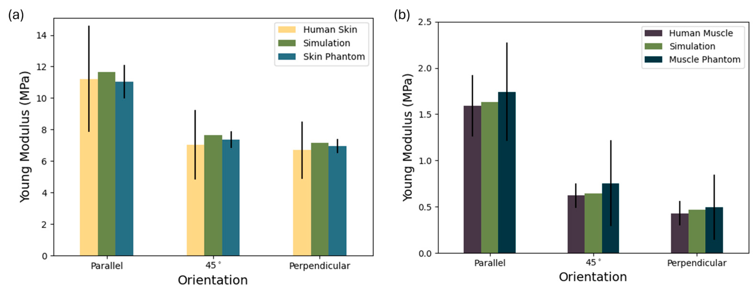
Figure 7. To compare against the values in the literature, the values of Young’s modulus presented here were calculated using the second Piola–Kirchhoff stress tensor.
Figure 7a demonstrates not only the anisotropic mechanical behavior of the materials but also the consistency and reproducibility of the proposed silicone–natural fiber composite phantom relative to biological skin. The human skin data [
58] exhibit high variability—particularly in the parallel orientation—where the standard deviation exceeds ±3.0 MPa. This reflects the known heterogeneity of biological tissue due to anatomical location, age, and testing protocols. The composite phantom, formulated with 6% natural fibers in a silicone matrix successfully reproduces the directional dependence of Young’s modulus observed in real skin. In the parallel direction, its modulus (11.04 MPa) is slightly below that of the simulation, but both are well-aligned with the human skin mean (±10.5 MPa). Similar close matches are seen at 45° (7.36 ± 0.554 MPa) and perpendicular orientations (7.16 ± 0.45 MPa), where deviations from the biological reference remain within experimental error.
Overall, the low variability in the skin phantom and the strong agreement with both simulation and literature values underscore the effectiveness of using simulation-based design to tune mechanical anisotropy via natural fiber reinforcement. This supports the phantom’s suitability for use in skin-mimicking applications where directional stiffness is critical, such as ultrasound phantoms, surgical training, or elastography validation.
In
Figure 7b it is possible to observe the Young’s modulus of human muscle [
57], a simulated composite, and a corresponding muscle phantom across three orientations: parallel, 45°, and perpendicular to the muscle fiber direction. The muscle phantom closely replicates both the magnitude and directional trend of the biological tissue. The human muscle exhibits clear anisotropic mechanical behavior, with the highest stiffness along the fibers (1.743 ± 0.312 MPa), which drops markedly at 45° (0.754 ± 0.465 MPa) and even further in the perpendicular direction (0.494 ± 0.352 MPa). This reflects the natural alignment of muscle tissue, which is structurally optimized for tensile loads along the fiber axis. Notably, in the parallel direction, the phantom slightly exceeds the simulation, although the standard deviation is relatively well-contained, suggesting good uniformity in material fabrication despite biological variability. At the 45° and perpendicular orientations, the phantom maintains the expected decrease in modulus, though the standard deviation increases likely due to fiber misalignment or interfacial effects within the composite. Still, the phantom and simulation remain within the error range of human muscle values, indicating strong bio fidelity in mechanical anisotropy.
This result confirms that the silicone–fiber composite, guided by simulation-based design, can effectively mimic the passive anisotropic mechanics of skeletal muscle. The controlled standard deviation, especially when compared with the broad variability of biological samples, supports the phantom’s relevance for applications like ultrasound elastography, rehabilitation device testing, and biomechanical modeling, where realistic anisotropy is critical.
The observed variability is likely attributed to the very low fiber content (0.5%), which demands high-precision dispersion and mixing techniques during fabrication. At such low reinforcement levels, even minor inconsistencies in fiber distribution or alignment can have a significant impact on mechanical performance, making the material more difficult to reproduce consistently. Due to the low fiber content required in our composite samples, accurately measuring fibers with a high-precision scale can be challenging, particularly for small-scale samples, lending to a high standard deviation. However, scaling up production for full-size structures will increase the fiber quantity, significantly improving measurement precision and ensuring minimal mass loss. Additionally, the depth of each phantom layer can be finely adjusted to match individual patient anatomy, providing customizable solutions beyond the specific layer depths used in this study.
3.2. Dynamic Mechanical Response Results
To evaluate the mechanical behavior of the fabricated phantoms, the storage modulus (
), loss modulus (
), and complex modulus (
) were experimentally measured across a frequency range of 3 to 10 Hz. These viscoelastic parameters were extracted from the stress–strain hysteresis loops and are presented in
Figure 8.
The storage modulus (
Figure 8a) provides insights into the elastic energy stored per deformation cycle. The control sample, composed of pure silicone, consistently displayed the lowest
E′ values across all frequencies (1.135 to 2.274 kPa). These values place it below the lower bound of the physiological skin range. Upon the addition of natural fibers, the skin phantom sample demonstrated a significant increase in stiffness (
E′ of 2.032 to 4.521 kPa), aligning well with the shaded skin range and demonstrating frequency-sensitive stiffening behavior consistent with soft biological tissues. This behavior confirms effective mechanical reinforcement at low fiber loading without overshooting the skin range. Regarding the skeletal muscle phantom, a steep increase in modulus with frequency was observed (
E′ of 2.819 to 6.652 kPa), mirroring the dynamic stiffening observed in biological skeletal muscle, suggesting that the composite design not only matches the static stiffness of muscle but also mimics its rate-dependent mechanical behavior. The increase observed in storage modulus with fiber addition stems primarily from the reinforcing effect of the fibers within the silicone matrix. Natural fibers are significantly stiffer than the base elastomer, and when embedded, they act as load-bearing elements that restrict matrix deformation. This leads to a higher capacity for elastic energy storage under cyclic loading. Additionally, the mechanical interaction between fibers and matrix facilitates effective stress transfer, further boosting the composite stiffness. Even if fiber alignment is not aligned with the load, their presence introduces anisotropy and microstructural resistance, especially at higher frequencies, where the dynamic stiffness of the material becomes increasingly pronounced.
The energy lost as heat per cycle is quantified by the loss modulus (
E″) and is shown in
Figure 8b. Here, the control once again occupies the lowest region, with
E″ ranging from of 0.1813 to 0.2495 kPa. While this damping is non-negligible, it remains below the physiological thresholds of both skin and muscle, consistent with pure silicone’s low energy dissipation profile. Regarding the skin phantom sample, the addition of natural fibers resulted in an increase in the loss modulus (
E″ of 0.3546 to 0.5453 kPa), residing comfortably within the muscle range at lower frequencies and trending toward the lower skin range as frequency increases. This suggests that even with modest fiber contents, the viscous contribution becomes substantial, likely due to interfacial friction and local matrix–fiber interactions. The skin phantom thus exhibits a damping profile that reflects real tissue behavior under oscillatory loads (
E″ of 0.5226 to 0.8546 kPa), where internal friction plays a major role in shock absorption and wave attenuation. This sample displayed the highest damping values, closely matching the trajectory of the upper muscle band. This behavior supports the hypothesis that higher fiber volume fractions amplify internal dissipation mechanisms through fiber–matrix slippage, microscale shear lag, and enhanced heterogeneity. Moreover, the observed peak and slight decline at higher frequencies mirror experimental muscle behavior and may indicate the onset of dynamic saturation effects or reduced fiber mobility. The rise in loss modulus is most likely attributed to increased internal friction and energy dissipation mechanisms introduced by the fibers. As the matrix deforms around the embedded fibers, interfacial friction and micro-slip events occur at the fiber–matrix boundary, converting part of the mechanical energy into heat. Moreover, the mismatch in viscoelastic response between fibers and matrix causes phase lags and localized stress concentrations, enhancing viscous damping. Dynamic effects such as fiber reorientation and viscoelastic drag further amplify energy loss per cycle. Together, these mechanisms result in composites that are not only stiffer but also exhibit enhanced damping, mimicking the dual viscoelastic nature of fibrous biological tissues like skin and skeletal muscle.
The complex modulus (
Figure 8c) synthesizes both elastic and viscous contributions, representing the total mechanical resistance to deformation. Unsurprisingly, all phantom types followed trends consistent with their respective
and
values. The control sample remained well below both biological ranges (
of 2.139 to 3.376 kPa), while the skin (
of 4.087 to 7.083 kPa) and muscle (
of 5.938 to 10.829 kPa) phantom samples rose sharply with frequency, demonstrating clear differentiation in mechanical impedance. Importantly, both phantom formulations exhibited progressive frequency-dependent stiffening, a hallmark of viscoelastic soft tissues. This behavior is critical to applications in ultrasound phantoms and biomechanical surrogates, where accurate acoustic and mechanical responses are essential to mimicking the dynamic mechanical environment of human tissue. The skin phantom sample serves as a robust replacement for skin, while the muscle phantom sample closely follows the complex modulus profile of skeletal muscle.
Our results, where the storage modulus (
E′) consistently exceeds the loss modulus (
E″), align with the behavior reported by Manickam et al. for agar-based tissue phantoms [
59]. This relationship reflects the typical viscoelastic signature of soft tissues. While Manickam et al. achieved stiffness tuning through agar concentration, our fiber-reinforced silicones achieve similar control via structural reinforcement. As Manickam highlighted, dynamic moduli like
E″ and
E* prove more effective than static elasticity in distinguishing tissue classes, as reinforced by our findings. When comparing our results to those of Kazemirad et al., who assessed shear moduli over a high-frequency range (200–1000 Hz), it is important to note that their reported shear storage moduli (
G′), ranging from 1.5 to 2.5 kPa [
60], fall within expectations for soft gels under shear loading. In contrast, our measured storage moduli (
E′) in uniaxial compression range from ~110 to 670 kPa at much lower frequencies (3–10 Hz). This difference in magnitude is consistent with both the loading mode (
E′ ≈ 3
G′) and the strain-rate dependence of viscoelastic materials, which typically exhibit increasing stiffness with frequency. Despite the disparity in testing bandwidth, both studies demonstrate the same trend: mechanical reinforcement (via castor oil or natural fibers in our case) increases both stiffness and damping. Their rise in damping behavior, reflected by tan δ increasing from 0.11 to 0.26, aligns with our increase in
E″ and suggests that fiber reinforcement can replicate the viscoelastic modulation typically achieved through compositional tuning in gels, offering a structurally tunable route to biomimicry even at lower, physiologically relevant frequencies. Compared with the PVA-based phantom developed by Guo et al., which exhibited an elastic modulus of 1.34 ± 0.28 kPa and a viscosity of 9.67 ± 3.00 Pa·s [
61], our silicone-based phantoms demonstrate substantially higher stiffness and damping values. This difference is expected due to both the material system and the loading conditions, since Guo’s rheological measurements were performed under shear at low strains, while our phantoms were tested under cyclic compression. Translating our storage modulus (
E′) into comparable terms, its values ranged from 110 to 670 kPa, with the increase in fiber content leading to greater stiffness. While Guo et al. validated their phantom against liver tissue (elasticities from 0.9 to 2.9 kPa and viscosities up to 14.4 Pa·s), our results target fibrous soft tissues like skin and skeletal muscle, which inherently exhibit higher resistance to deformation. These findings highlight that material selection and structural reinforcement strategies must be tailored to the mechanical regime of the target tissue and confirm that our fiber-reinforced silicone composites are well-suited for mimicking the mechanics of stiffer, anisotropic biological structures. Our results differ markedly from those of Nguyen et al., who found that adding castor oil to gelatine phantoms decreased the shear modulus, from 2.01 kPa to 0.88 kPa while slightly increasing viscosity [
62]. In contrast, our fiber-reinforced silicone phantoms showed a simultaneous increase in both stiffness and damping, with
E′ rising from 110 to 670 kPa and
E″ from 180 to 860 kPa as the fiber content increased. This reflects a key distinction in tuning strategy: while castor oil softens the matrix, fibers structurally reinforce it, enhancing both load-bearing capacity and energy dissipation. As a result, our composites more effectively replicate the viscoelastic behavior of fibrous biological tissues, without the stiffness–damping trade-off observed in oil–gelatine systems.
Our results demonstrate that natural fiber-reinforced silicone composites enable the precise tuning of viscoelastic properties, effectively replicating the behavior of soft tissues like skin and muscle. Unlike traditional gel-based phantoms, these composites achieve simultaneous increases in stiffness and damping while offering greater durability, lower production cost, and enhanced sustainability using natural fibers. This makes them a high-performance, eco-conscious, and scalable solution for novel tissue-mimicking applications.
3.3. Linear Ultrasound Characterization Results
The results expressed in
Figure 9 clearly demonstrate the feasibility of tuning the acoustic properties of elastomeric phantoms toward biologically relevant values through compositional and structural modifications.
In
Figure 9a, the LWS of the control phantom (1086 ± 38 m/s) remains below 1150 m/s, consistent with the compliant, unreinforced silicone matrix. This reflects the low-stiffness and high-compressibility characteristics of soft hyperelastic polymers. The simulation result for the control sample (1087 m/s) closely matches the experimental value, supporting the accuracy of the model. Notably, the skin phantom formulation exhibits a modest increase in LWS (1090 ± 50 m/s), with a corresponding simulated value of 1112 m/s. The muscle phantom reaches median values approaching 1200 m/s (1127 ± 48 m/s), with the simulation yielding 1134 m/s, representing a 9% enhancement over the control. This progressive increase confirms the effectiveness of formulation strategies in modulating LWS, although values remain below native tissue benchmarks (skin: 1540–1600 m/s [
63]; muscle: 1500–1700 m/s [
64,
65]). When compared with the existing literature, the longitudinal wave speeds (LWSs) obtained in this study align well with values reported for other soft-tissue phantom materials. For instance, Hirata et al. developed a urethane-rubber-based phantom with a reported LWS of 1200 m/s [
66]. Similarly, Suzuki et al. investigated an oil–gel phantom composed of SEBS in paraffin oil for simulating fatty breast tissue, observing LWS values lower than water—particularly at temperatures above 20.6 °C—indicating a typical range near or below 1200–1300 m/s [
67]. Even widely used agarose-based phantoms, such as the ones used by López-Haro et al., known for their acoustic transparency and biological relevance, can drop below 1300 m/s under specific thermal or concentration conditions [
68].
Figure 9b presents a compelling picture in terms of attenuation behavior. The control phantom exhibits minimal attenuation (0.13 ± 0.02 dB/cm/MHz), aligning with expectations for a homogenous, low-viscosity silicone matrix with minimal internal scattering or energy dissipation. Upon modifying the composition, both the skin and muscle phantoms, however, display significant increases in attenuation (0.32 ± 0.07 and 0.76 ± 0.08 dB/cm/MHz, respectively) and demonstrate clear increases in attenuation within the bounds of physiological tissue ranges (skin: 0.094–0.70 dB/cm/MHz [
69]; muscle: 0.5–1.3 dB/cm/MHz [
70]). When compared against other studies, the performance of these phantoms stands out. For instance, Rubert and Varghese reported attenuation values in soft-tissue-mimicking phantoms ranging between 0.4 and 0.5 dB/cm/MHz [
71], while O’Neill et al. designed a regulatory-compliant TMM with a fixed attenuation of 0.3 dB/cm/MHz [
72], a value comparable to the muscle phantom presented here, despite the latter being constructed using low-cost, moldable silicone. Similarly, Nagabhushana et al. documented attenuation values as low as 0.5 dB/cm/MHz [
73] but required post-processing correction methods to estimate them accurately, whereas the current phantoms exhibit predictable, measurable attenuation without the need for correction. Notably, Aoyagi et al. developed calcium alginate phantoms with a reported mean attenuation of 0.54 ± 0.18 dB/cm/MHz [
74], overlapping with biological ranges but using hydrogels that may suffer from dehydration, fragility, and thermal instability. The progressive enhancement in attenuation reflects the growing acoustic heterogeneity within the matrix, likely resulting from altered viscoelastic behavior and microstructural scattering. The wider range of attenuation in the muscle phantom results suggests a more complex internal structure and variable acoustic properties, similar to the non-uniform and anisotropic nature of real muscle tissue.
Unlike hydrogel- or oil-based phantoms, which often exhibit significant thermal sensitivity and require strict storage conditions to maintain structural integrity, the silicone-based matrix used here remains mechanically stable across a broad temperature range, including room temperature and above, ensuring consistent acoustic performance without the risk of melting, dehydration, or oil separation. This is particularly relevant in contrast to gel-based phantoms such as those developed by Suzuki et al., which demonstrate speed-of-sound reductions and potential softening or phase instability above 20–25 °C [
67], a range frequently encountered in laboratory and clinical environments. Furthermore, the dry, inert nature of the silicone matrix eliminates the need for preservatives, refrigeration, or sealed storage, offering a low-maintenance, reusable alternative to conventional water-rich phantom materials.
From a bioinspired materials perspective, these results validate the strategy of tunable acoustic biomimicry via low-cost, moldable elastomeric composites. While LWSs are still below target tissue values, the significant improvements over the control, especially in attenuation, mark a meaningful step toward physiologically relevant phantoms. Further enhancements, such as directional gradient stiffness layering, matrix reinforcement, or the incorporation of a liquid phase, are expected to bridge the remaining gap, particularly for the high-fidelity simulation of anisotropic tissues like skeletal muscle.
3.4. Shear Wave Elastography Results
Figure 10 clearly demonstrates distinct SWS variations among the three phantom types tested. The observed differences indicate the successful tuning of phantom stiffness and anisotropic properties, intended to mimic biological tissue characteristics.
The ultrasound imaging clearly revealed differences in the structural composition of the evaluated phantom samples. The control phantom (
Figure 10a) exhibited uniform ultrasound characteristics with a homogeneous and isotropic silicone structure, indicating no observable internal fiber reinforcement or anisotropic structures.
In contrast, the laminated skin phantom (
Figure 10b,c), distinctly showed two separate layers: the upper layer composed exclusively of silicone, appearing uniform and homogeneous, and the bottom layer containing natural fibers dispersed within the silicone matrix. This structural difference was directly observable, providing clear confirmation of successful fabrication and layer differentiation. When the ultrasound beam traversed the sample parallel to the fiber orientation, a significant increase in shear wave velocity was consistently observed compared with the silicone-only layer, and the architecture of the fibers was clearly visible in the ultrasound images (
Figure 10b), reaching an SWS of 2.98 ± 0.72 m/s. Notably, when the beam orientation was perpendicular to the fiber direction, a reduction in shear wave velocity was observed, highlighting the anisotropic nature imparted by the fibers (
Figure 10c), reaching an SWS of 3.58 ± 0.33 m/s. This phenomenon highlights the crucial role of natural fibers, acting both as structural reinforcement and as agents that alter and disperse mechanical waves, thus increasing overall shear wave speed.
The muscle phantom (
Figure 10d,e) revealed distinct anisotropic behavior characterized by a heterogeneous ultrasound image due to fiber alignment and density variations within the silicone matrix. Ultrasound measurements demonstrated considerable variation in shear wave velocities dependent on fiber orientation relative to the ultrasound beam. When the beam was parallel to the fibers, higher velocities were observed, and the clear visibility of fibers was similar to the ultrasound appearance of skeletal muscle (
Figure 10d), reaching an SWS of 4.43 ± 0.74 m/s. Conversely, when the beam was perpendicular to the fiber direction, ultrasound images showed less distinct fiber architecture and a decrease in shear wave velocities (
Figure 10e), reaching an SWS of 5.93 ± 0.62 m/s.
This anisotropic contrast further confirmed the fibers’ reinforcing and wave-dispersing roles, effectively mimicking the mechanical behavior typical of skeletal muscle tissue. The use of ultrasound coupling gel between the layers additionally created imaging characteristics resembling adipose tissue, further enhancing the biological realism of the phantom.
These findings emphasize the dual functionality of fibers in composite phantom design. By acting simultaneously as reinforcing elements and wave-dispersing agents, fibers enhance the mechanical integrity of the phantoms and replicate the anisotropic wave propagation behaviors observed in biological tissues. This dual role reinforces the suitability of natural fiber–elastomer composites as versatile, tunable, and biologically representative ultrasound medical phantoms.
Regarding the SWSs observed, starting with the control phantom (1.5 ± 0.22 m/s), these were relatively low, consistently falling below 2 m/s, indicating that this material presented properties typical of soft, isotropic silicone without fiber reinforcement. This is in line with expectations, as control phantoms typically aim to represent baseline isotropic and softer properties compared with biologically anisotropic tissues. The simulation result for the same phantom, which yielded a shear wave speed of 1.46 m/s, closely aligns with the experimental measurements, further validating the accuracy of the simulation approach and the chosen material parameters for modeling the silicone matrix.
In contrast, the skin phantom demonstrated SWSs within the range of 3.65 ± 0.51 m/s. This closely matches the reported stiffness of human skin tissue, as depicted by the highlighted region labeled “Skin” in the graph (2.87–5.31 m/s [
75]). The relatively narrow dispersion of SWS values indicates uniform stiffness and the successful tuning of the phantom to represent human skin elasticity. This alignment suggests the appropriateness of the phantom composition and fiber reinforcement approach to mimic human skin effectively. Additionally, the simulation of this sample yielded a shear wave speed of 3.74 m/s, which is in strong agreement with experimental results and further supports the validity of the model assumptions and the mechanical characterization of the composite.
The muscle phantom presented a broader variability in SWS, with values of 5.93 ± 0.62 m/s, thus spanning the range reported in the literature for human skeletal muscle tissue, highlighted as “Muscle” in the graph (2.5–8.3 m/s [
76]). The increased variability is likely related to the anisotropic nature of muscle, in which fiber orientation significantly influences elastic properties. Therefore, measuring parallelly and perpendicularly to the fiber orientation could contribute significantly to this observed dispersion. This finding reinforces that the phantom structure successfully emulated the anisotropic behavior characteristic of skeletal muscle. Furthermore, the simulation of the muscle phantom yielded a shear wave speed of 5.44 m/s, which falls within the experimental range and further supports the model’s capability to reproduce both the magnitude and variability of wave propagation in anisotropic composite structures.
Tsai et al. investigated scar elasticity using high-frequency ultrasound (HFUS) elastography with the Lamb wave model, demonstrating improved accuracy compared with traditional shear wave models. They utilized gelatine-based phantoms and validated their approach clinically, reporting SWSs of 1.66 ± 0.05 m/s and 2.69 ± 0.03 m/s for the two phantoms produced [
77]. However, our study presents similar SWS performance and significant improvements by using silicone-based composites embedded with natural fibers, providing tunable anisotropic properties closely resembling skin and skeletal muscle.
Ultrasound phantoms commonly group skin, muscle, and fat into a single simplified layer, reducing anatomical realism and potentially affecting the accuracy of shear wave elastography, Doppler assessments, and training simulations. Such simplified models fail to accurately replicate the mechanical impedance mismatch among these tissues, leading to distorted wave propagation and calibration errors [
78]. In this study, we address these limitations by developing silicone-based multilayer composites reinforced with natural fibers, clearly distinguishing skin from underlying tissues. Our approach provides enhanced anatomical accuracy, realistic mechanical impedance matching, and improved validity for ultrasound imaging applications.
Dong et al. developed 3D-printed alginate-based skeletal muscle phantoms using a modified FRESH hydrogel method to create highly biomimetic models suitable for controlled SWE assessments. The authors reported an average SWS of approximately 4.08 m/s [
79]. When compared with our results, the muscle phantoms developed using silicone-based composites embedded with natural fibers demonstrated a broader and higher range of SWS values. This wider range highlights the enhanced tunability and anisotropic properties achieved through our approach. Tsuchida et al. measured an average SWS of 2.2 m/s using a phantom jelly material [
80]. This value is lower than typically reported for skeletal muscle and other fibrous tissues. In contrast, our silicone-based muscle phantom exhibited SWS values more closely matching the expected physiological range for skeletal muscle. Aristizábal et al. developed anisotropic gelatine-based phantoms using both fibrous materials and fishing lines to mimic soft-tissue mechanics. They reported shear wave speeds ranging from 2.44 to 4.10 m/s, depending on fiber orientation and gelatine concentration. Notably, phantoms with 14% gelatine showed greater anisotropy, with SWS values of 4.10 ± 0.11 m/s (0°) and 3.90 ± 0.02 m/s (90°) for fibrous composites [
81]. In comparison, our silicone-based muscle phantoms achieved a broader and higher range of shear wave speeds, reflecting stronger anisotropic behavior and tunability. These discrepancies bring to light the limitations of gelatinous materials in replicating the mechanical properties of anisotropic tissues, while reinforcing the effectiveness of our fiber-reinforced silicone composites in achieving realistic biomechanical behavior. Moreover, when compared with all other authors, the use of silicone significantly increases the durability and longevity of our phantoms compared with alginate-based materials, making our models better suited for long-term clinical training and repeated SWE measurements.
The developed silicone-based anisotropic phantoms reinforced with natural fibers present a durable, low-cost, and sustainable alternative to conventional tissue-mimicking materials. By offering tunable mechanical properties and realistic anatomical layering, these phantoms effectively replicate the complexity of fibrous biological tissues such as skin and skeletal muscle. Their extended lifespan, reusability, and use of natural, biodegradable reinforcements make them especially suitable for long-term training, imaging calibration, and research in ultrasound elastography.
4. Conclusions
In this study, sustainable, tunable, low-cost anisotropic vibrational and ultrasound phantoms were successfully engineered using a natural fiber-reinforced silicone matrix to emulate the mechanical and acoustic behavior of skin and skeletal muscle tissues. The proposed phantoms not only demonstrated clear anisotropy and fibrous tissue-mimetic properties but also achieved biomechanical fidelity across a range of key ultrasound parameters.
The viscoelastic behavior, quantified via storage, loss, and complex moduli showed that the natural fiber-silicone composites can be tailored to reproduce the nonlinear frequency-dependent mechanics of real tissues. This opens doors to mimicking a wider range of fibrous biological tissues by simply adjusting the fiber orientation, volume fraction, or matrix formulation.
Acoustic characterization confirmed that both longitudinal wave speeds and sound absorption coefficients fall within physiologically relevant bounds, reinforcing the viability of these phantoms for diagnostic and therapeutic ultrasound applications. The shear wave elastography results reveal that our skin and muscle phantoms closely replicate the expected shear wave speed ranges of real biological tissues, exhibiting direction-dependent stiffness comparable to native biological tissues anisotropy.
In contrast to conventional synthetic phantoms, our approach relies on biodegradable and biological components, advancing a circular materials strategy for medical device development and experimental validation. With this work, we not only provide a new toolkit for ultrasound research and training but also pave the way for eco-conscious, scalable alternatives in biomedical phantom engineering.


 ,
, 


