Article

Fracture Mechanics-Based Modelling of Post-Installed Adhesive FRP Composite Anchors in Structural Concrete Applications

Department of Engineering, Brock University, St. Catharines, ON L2S 3A1, Canada
*
Author to whom correspondence should be addressed.
J. Compos. Sci. 2025, 9(6), 282; https://doi.org/10.3390/jcs9060282
Submission received: 13 May 2025 / Revised: 28 May 2025 / Accepted: 29 May 2025 / Published: 31 May 2025

Abstract

:
Adhesively bonded fibre-reinforced polymer (FRP) anchors have emerged as a progressive alternative to traditional steel anchors in concrete structures, owing to their superior corrosion resistance, high tensile strength, and light weight. Despite their increasing use, a robust mechanics-based bond model capable of accurately predicting the load transfer behaviour has not yet been developed. This study presents a fracture mechanics-based analytical bond model for post-installed adhesive FRP anchors embedded in concrete. The model formulation is derived from fundamental equilibrium and compatibility principles, incorporating a bilinear bond–slip law that captures both elastic and softening behaviours. A new expression for the effective bond length is also proposed. Validation of the model against a comprehensive database of direct pull-out tests reported in the literature shows excellent agreement between predicted and experimental pull-out forces (R2 = 0.980; CoV = 0.058). Future research should aim to extend the proposed model to account for confinement effects, long-term durability, the impact of adhesive type, and cyclic loading conditions.

1. Introduction

Over the past decades, fibre-reinforced polymer (FRP) composite anchors have gained increasing attention in structural applications due to their high strength-to-weight ratio, corrosion resistance, and electrical non-conductivity [1,2,3,4,5]. These advantages make FRP anchors particularly suitable for modern construction needs, including: (1) connection of prefabricated FRP or steel elements to existing concrete structures [1]; (2) load transfer across new-to-old concrete joints [2]; and (3) shear strengthening of reinforced concrete (RC) members using embedded through-section (ETS) methods (Figure 1a,b) [3,4,5].
Although FRP anchors are emerging as an attractive alternative to steel-based systems, much of the existing anchorage design knowledge stems from earlier work on cast-in-place and post-installed mechanical anchors made of steel [6,7,8]. These systems are now well-established in major building codes and design standards such as ACI 318-25 [9], ACI 355.4-19(21) [10], CSA A23.3:24 [11], Caltrans 2020 [12], and IBC 2024 [13]. In structural practice, advanced composite post-installed adhesive anchors, play a key role in diverse applications such as (1) anchoring base plates on RC pedestals [14]; (2) seismic retrofitting [15]; (3) attachment of façade systems [16]; (4) support of mechanical, electrical, and plumbing components [17]; (5) installation of safety-critical elements like guardrails and handrails [18]; and (6) integration of new structural elements with existing concrete infrastructure [19].
Peier [20] developed one of the earliest advanced bond models for post-installed adhesive steel anchors by benefiting from a nonlinear finite element approach to incorporate concrete fracture and plasticity models. The model simulated the tensile behaviour of three single anchor types: adhesive, expansion, and form-fit anchors. The model’s accuracy was verified by comparing it with existing experimental data. To support the formulation of design provisions for adhesive anchors, Eligehausen et al. [21] carried out an extensive programme of numerical simulations and experimental testing focused on the behaviour of adhesively bonded steel anchor systems. This investigation led to the development of the Eligehausen, Popov, and Bertero (BPE) [21] bond-slip relationship for deformed post-installed steel anchors in concrete. In 1997, Cosenza et al. [22] redeveloped the BPE relationship for post-installed adhesive FRP anchors and proposed the Cosenza, Manfredi, and Realfonzo (CMR) [22] bond-slip relationship. However, their investigation did not suggest a relationship for the pull-out force for FRP anchors. Robinson and Said [23] used artificial neural networks (ANNs) to estimate the tensile strength of adhesive anchors in uncracked concrete, considering the influence of geometric and material parameters.
In addition, Ahmed et al. [24] conducted a comprehensive experimental study on the tensile pullout capacity of glass FRP (GFRP) post-installed adhesive anchors in concrete, evaluating the effects of bar diameter, embedment depth, adhesive type, and installation conditions. Their findings demonstrated that adequate performance was achieved with epoxy adhesives in wet conditions and with cement-based adhesives in dry conditions, particularly at embedment depths of 10–15 db, where db is the diameter of the anchor. Moreover, Valerio et al. [25] investigated the bond performance of adhesive FRP anchors in concrete through a series of direct pull-out tests. Godat et al. [26] conducted thirteen direct-shear test specimens on FRP bars adhesively bonded to concrete blocks. The results of this study revealed that by increasing the concrete strength, the bond strength increased, and the failure mode was changed. Raicic et al. [27] tested RC push-off specimens strengthened with anchored FRP and steel bars across a shear plane to assess the shear capacity and the failure mechanism of the test specimens. Caro et al. [28] tested the bond behaviour of GFRP and carbon FRP (CFRP) bars adhesively anchored into concrete prisms. It was seen that the bond strength and initial stiffness of the bond stress-slip curves decreased with the increase in the embedded lengths. Moreover, Caro et al. [28] proposed an analytical model for predicting the bond strength of FRP bar anchors and validated the model against experimental results. In addition, Bui et al. [29] conducted experimental and numerical studies on RC beams with steel and GFRP ETS bars using mechanical anchorage at the tension ends. In their study, the effectiveness of their developed bond stress-slip model was demonstrated with the results obtained from finite element modelling of the tested joints. Sogut [30] conducted two-dimensional nonlinear finite element analysis of RC beams strengthened with embedded steel bars in the absence of conventional transverse shear reinforcement. The results indicated that increasing the beam width led to a reduction in the relative shear strength enhancement provided by the ETS bars. Additionally, the study showed that larger beam dimensions corresponded with lower shear stress at failure in both unstrengthened and ETS-strengthened beams. Dutta et al. [31] also employed two-dimensional nonlinear finite element analysis to simulate continuous RC T-beams retrofitted with ETS bars made of either CFRP or steel. Their parametric analysis demonstrated that the predicted shear capacity of both unretrofitted and retrofitted beams improved with higher concrete compressive strength and increased effective depth. Vertical and inclined configurations of ETS bars were both considered in their models.

2. Research Significance
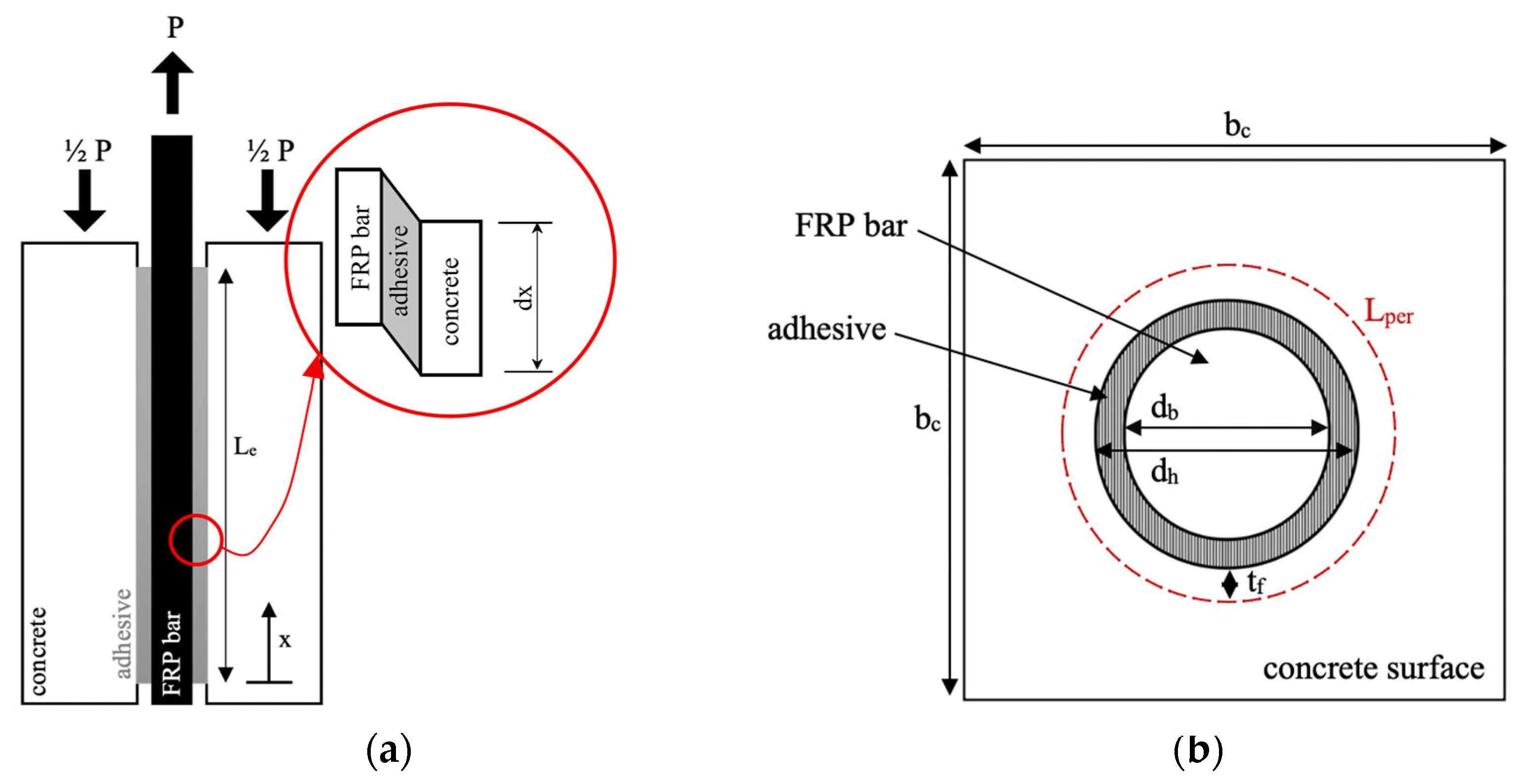
To address the lack of predictive models for FRP anchor systems, this study develops a mechanics-based bond model tailored for post-installed adhesive FRP anchors in concrete. The model is formulated through a rigorous analytical procedure grounded in fracture mechanics and bond–slip theory, capturing both the elastic and softening phases of interfacial behaviour. A central objective of the study is to establish a closed-form equation for predicting the pull-out force of FRP anchors based on material and geometric properties, enabling rational design beyond empirical methods. This study outlines the step-by-step development of an analytical bond model for post-installed adhesive FRP anchor bars, emphasising the methodology used to derive the key parameters within a fracture mechanics-based framework. These parameters are evaluated against the existing experimental results in the literature.

3. Bond Model

In developing the proposed bond model, several assumptions were made as follows: (1) the adherents are considered linear-elastic and homogeneous; (2) bending effects are neglected; (3) normal stresses are uniformly distributed across the FRP composite bar’s cross-section; (4) the diameter, width, and thickness of the adherents and adhesive remain constant along the bond line; (5) the thickness of the failure plane provides a uniform concrete cover around the FRP bar and along its pull-out length; (6) both the adhesive and concrete possess sufficient strength to ensure that failure occurs solely by pull-out; and (7) the adhesive serves only to transfer shear stress from the FRP bar to the surrounding concrete.
Considering the anchored FRP/concrete joint shown in Figure 2a,b, the equilibrium equation can be written as follows:
d σ b d x τ L P E R A b = 0
where σ b and A b are the normal stress and cross-sectional area of the FRP bar, respectively, and L p e r , the length of the debonding failure plane is calculated as follows:
L p e r = 2 π d h 2 + t f
where dh is the hole diameter and tf is the thickness of the concrete cover surrounding the FRP bar, the interface at which the shear failure takes place. This relationship can be simplified as Lper = πdf, where df combines the dh and tf terms to represent the effective diameter of the failure plane.
Since the adherents are assumed to be linear elastic, their elastic extension is illustrated as shown in Figure 3, and the corresponding slip is defined by Equation (3).
δ = u 1 u 2
where u1 and u2 represent the individual displacements of the FRP anchor and the concrete block, respectively, as illustrated in Figure 3.
Taking the second derivative of Equation (3) yields:
d 2 δ d x 2 = d 2 u 1 d x 2 d 2 u 2 d x 2
Considering Hooke’s law for FRP bar ( σ b = E b d u 1 d x ) and for concrete, ( σ c = E c d u 2 d x ), and taking the second derivative of the displacements u1 and u2, leads to Equations (5) and (6), respectively:
d 2 u 1 d x 2 = 1 E b d σ b d x
d 2 u 2 d x 2 = 1 E c d σ c d x
By substituting Equations (1), (5), and (6) into Equation (4), Equation (7) is obtained:
d 2 δ d x 2 τ   L p e r E b A b L p e r E c A c = 0
Here, by defining β as shown in Equation (9) and τ(x) as presented in Equation (10), Equation (7) can be transformed to Equation (8).
d 2 δ d x 2 f δ   β = 0
and
β = L p e r 1 E b A b 1 E c A c
τ   x = f δ
Since EcAc is significantly larger than EbAb, the last term in Equation (9) is negligible and can be omitted. Thus, Equation (9) simplifies to Equation (11):
β = L p e r E b A b
A double-branched shear-slip curve is adopted for the joint between the FRP anchor and the concrete (Figure 4a,b). Supporting experimental data for the adaptation of such a shear-slip curve is provided in the “Verification of Analytical Bond Model” section of this article. Stage I represents the initial elastic response of the joint, idealized as linear. Stage II captures the softening behaviour: once the joint reaches its τ m a x   at the corresponding slip value ( δ 1 ), interfacial fracture initiates and propagates. This progression is depicted by a gradually descending linear branch, which terminates at δ 2 rather than δ m a x as all available experimental studies concluded before the complete pull-out of the FRP bar. Therefore, the function f(δ) in Equation (10) is given by the following equations:
  • Stage I, for 0 ≤ δ δ 1
    f δ = τ m a x δ 1   δ
  • Stage II, for δ 1 < δ δ 2
    f δ = τ m a x δ 2 δ 1   δ 2 δ

3.1. Elastic Stage (Stage I)

By solving Equation (8) for Stage I, Equation (14) is obtained:
d 2 δ d x 2 τ m a x δ 1 δ   β = 0
d 2 δ d x 2 λ 1 2 δ = 0
where
λ 1 2 = β τ m a x δ 1  
Applying the initial boundary condition at x = 0 yields:
δ ( x ) = A s i n h ( λ 1 x )  
As shown in Figure 2a, the two curves intersect at x = L e a in δ 1 , where ‘a’ defines the fracture length. Therefore, x = L e a serves as the next boundary condition:
δ i L e a =   δ 1 =   A s i n h ( λ 1 L e a )
By applying Equation (12), Equation (19) is obtained:
τ i ( x ) = τ m a x s i n h ( λ 1 x )   s i n h ( λ 1 L e a )
By substituting Equation (19) into Equation (1), Equation (20) is obtained:
σ b . i ( x ) =   L p e r τ m a x A b λ 1 c o s h ( λ 1 x )   s i n h ( λ 1 L e a )

3.2. Softening Stage (Stage II)

The interfacial shear stress distribution is illustrated in Figure 1a, where Stages I and II meet at τ m a x . At this point, the bond begins to deteriorate, initiating interfacial fracture propagation within the concrete cover over a width equal to Lper, as represented by the descending branch of the bond–slip curve (Stage II). As the fracture progresses, shear stress is gradually transferred to the adjacent fully bonded segment of the FRP anchor, following the Stage I curve and shifting toward the unloaded end. The effects of friction from residual aggregate interlocking and residual friction at the debonded interface are neglected. To establish the initial formulation, the softening branch is substituted into the governing differential equation:
To set up the initial problem, the softening branch must be substituted into the governing differential equation:
d 2 δ d x 2 τ m a x δ 2 δ 1   δ 2 δ   β = 0
d 2 δ d x 2 + λ 2 2 δ δ 2 = 0
where
λ 2 2 = β τ m a x δ 2 δ 1  
Applying the initial boundary condition yields:
δ i i ( x ) = C c o s ( λ 2 x ) + D s i n ( λ 2 x ) + δ 2
It should be noted that at x = L e a , where the two curves intersect, the slip and normal stress for both stages satisfy δ i ( L e a ) = δ i i ( L e a )   and σ i ( L e a ) = σ i i ( L e a ) , with separate boundary conditions applied to solve the problem.
δ i L e a = δ i i L e a = δ 1 = C c o s ( λ 2 L e a ) + D s i n ( λ 2 L e a ) + δ 2
By applying Equation (13), Equation (26) is obtained:
τ i i ( x ) = τ m a x δ 2 δ 1   δ 2 ( C c o s ( λ 2 ( x ) ) + D s i n ( λ 2 ( x ) ) + δ 2 ) ,
By substituting Equation (26) into Equation (1), Equation (27) is obtained:
σ b . i i ( x ) = τ m a x L p e r A b δ 2 δ 1 C λ 2 s i n ( λ 2 x ) + D λ 2   c o s ( λ 2 ( x )
From σ i ( L e a ) = σ i i ( L e a ) , the second equation is obtained. Solving the simultaneous equations yields the final expression:
σ b . i i x = L p e r τ m a x A b λ 2   s i n λ 2 x L e + a + λ 2 λ 1 c o t h ( λ 1 L e a ) c o s ( λ 2 x L e + a )
Equation (29) can be derived by applying P = σ b A b , where x = Le to define the pull-out force along the fully bonded length:
P = L p e r τ m a x λ 2   s i n ( λ 2 a ) + λ 2 λ 1 c o t h ( λ 1 L e a ) c o s ( λ 2 a )
The maximum pull-out force occurs when d P d a = 0 , and thus:
P m a x = L p e r τ m a x λ 2   s i n λ 2 a + λ 2 2 λ 1 2 s i n λ 2 a
Using a similar approach for large Le values, and incorporating Φ to account for the properties of the FRP anchor and concrete, Pmax is derived as shown in Equation (31),
P m a x = L p e r τ m a x λ 2   δ 2 δ 2 δ 1 Φ
where
Φ = 1 1 + E b A b f c A c
and f c is the concrete specified compressive strength.

4. Discussions on the Behaviour of the Proposed Bond Model

To evaluate the accuracy of the proposed model, a comparative study was conducted using existing data from direct pull-out tests of post-installed adhesive FRP bar anchors in unconfined concrete blocks.

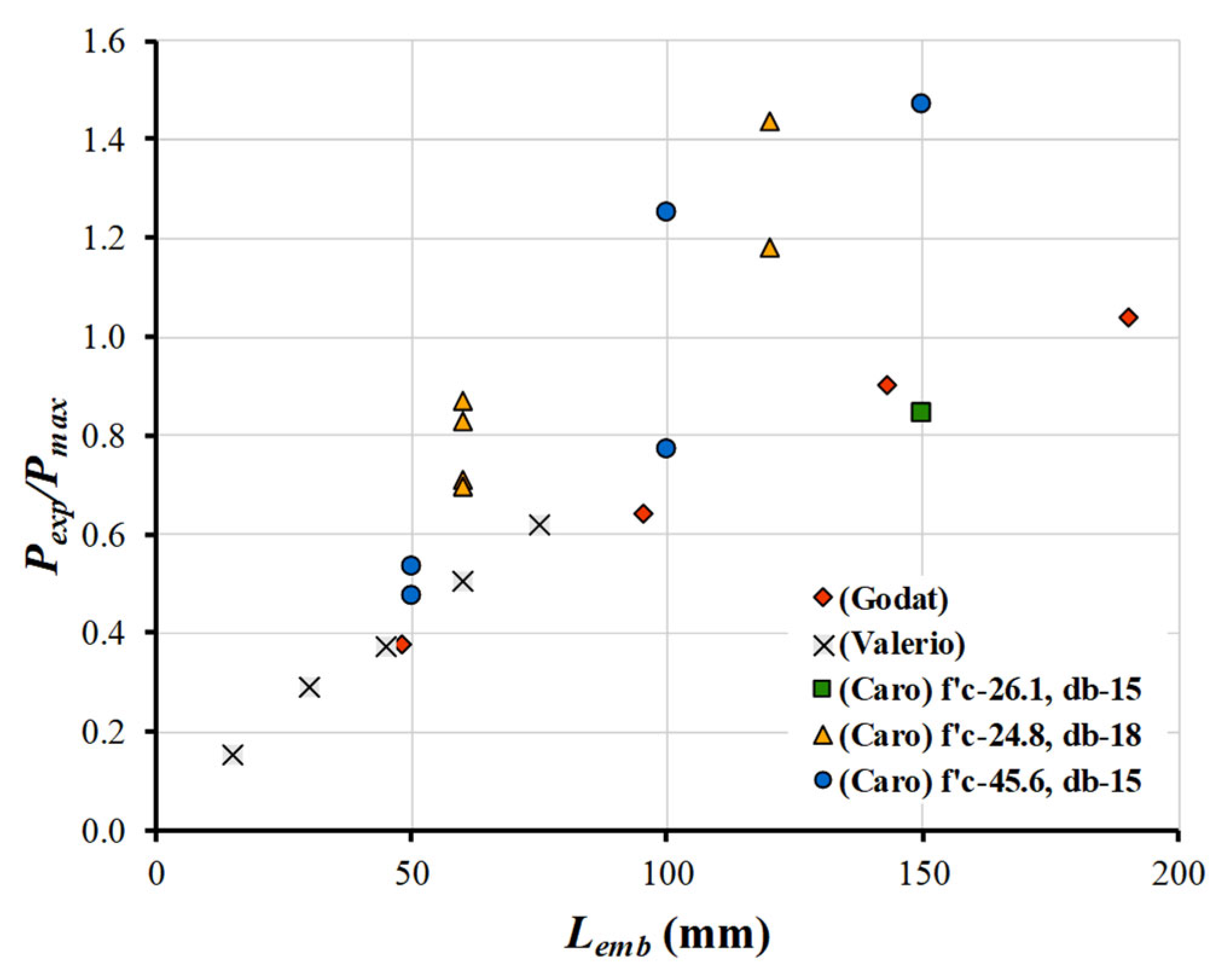
Predictions of the Proposed Model Versus Experimental Results

To validate the proposed bond model, direct pull-out tests reported by Valerio et al. [25], Godat et al. [26], and Caro et al. [28] were examined. Table 1 summarizes the properties of the FRP anchor pull-out test specimens from the literature. Table 2 presents the predicted Pmax calculated using Equation (31), which was derived from solving the governing differential equations. Additionally, Table 2 includes the ratio of Pexp to Pmax. In this study, the experimental maximum bond strengths reported in each referenced study were used to calculate Pmax and predict the pull-out force for each specimen in the database. However, the authors have generally developed analytical equations to predict τmax and δ1 as follows:
τ m a x = A × E f r p j × f c f × π   d b   L e k
δ 1 = G τ m a x m
where for CFRP anchors, A = 10−7.71, j = 1.81, f = 0.49 and k = −0.32; for GFRP anchors, A = 10−47.29, j = 10.58, f = 0.38 and k = −0.27; and for combined CFRP and GFRP anchors A = 0.34, j = 0.30, f = 0.62 and k = −0.24. Meanwhile, G = 9.06 and m = −0.73 are curve-fitting parameters calculated through linear regression. Details of the development of equations for the maximum shear stress and the corresponding slip are provided in Mirzabagheri et al. [4].
To this end, Equation (33) can be rewritten for combined CFRP and GFRP anchors as follows:
τ m a x = 0.245   E f r p 0.3 f c 0.62   d b   L e 0.24
Figure 5 shows the ratio of Pexp/Pmax versus the embedded length (Lemb, in millimetres) for each tested specimen, evaluating the sensitivity of the model predictions to changes in Lemb. Data sets from different studies are colour-coded. Except for four specimens from Caro et al. [28], an increase in Lemb generally led to improved accuracy across all specimens. The most notable improvement occurred with the specimens from Godat et al. [26], where increasing Lemb from 143 mm to 190 mm not only enhanced accuracy but also reduced the gradient of error, indicating convergence toward Le, in agreement with experimental results.
As reported by De Lorenzis and Nanni [32], Le represents the bond length beyond which the bond force no longer increases. A similar trend was observed for Valerio et al. [25], where increasing Lemb from 15 mm to 75 mm (approximately 10% to 50% of the effective length) reduced the Pmax prediction error from 85% to 35%. These findings highlight the fundamental influence of Lemb, relative to Le, on the debonding force.
For the Caro et al. [28] test specimens, a similar trend was observed; however, the model was less effective, as the predictions converged to overly conservative values for both CFRP and GFRP specimens. On the other hand, in the Godat et al. [26] results, the two larger specimens yielded the most accurate predictions, highlighting the critical role of sufficient bond length in the overall performance of Pmax.
To account for the effect of bond length in the proposed model, the equation developed by Mofidi et al. [33] was adopted to calculate the effective length of ETS FRP in concrete, as shown in Equation (36):
L e = E b d b δ 1 1 + α 2 τ m 1 α 2
where α is a calibration factor taken as 0.6 .
After calculating Le and comparing it with Lemb to assess the adequacy of the embedment length, the modified equation for Pmax is expressed as follows:
P m a x = k L p e r τ m a x λ 2   δ 2 L e m b δ 2 δ 1 L e Φ           I f   L e m b < L e ,
P m a x = k L p e r τ m a x λ 2   δ 2 δ 2 δ 1 Φ         I f   L e m b L e ,
where k is set to 1.2. The coefficient of determination (R2) between the predicted results from Equations (36) and (37) and the experimental data is 0.980 (Figure 6), with a coefficient of variation (CoV) of Pexp/Pmax equal to 0.058, which indicates excellent predictive accuracy of the proposed bond model. Table 3 shows the results of the calculations of P m a x for FRP anchor/concrete joints.

5. Recommendations

Based on the findings of this study, the following recommendations are proposed to enhance the design and application of post-installed adhesive FRP anchors in structural concrete:
  • The mechanics-based bond model developed in this study provides a predictive tool for estimating the pull-out capacity of FRP anchors. Practitioners and design engineers are encouraged to incorporate this model into design procedures.
  • The model’s predictions highlight the critical influence of embedment length on the pull-out force. Designers should consider the calculated effective bond length to ensure adequate anchorage, especially in applications where limited embedment is feasible.
  • When selecting adhesive types and concrete strengths, it is crucial to carefully consider adhesive curing conditions and environmental factors, as they significantly impact the overall bond performance and long-term durability of the anchor system.

6. Conclusions

This study developed a novel analytical bond model to predict the pull-out force of adhesively bonded FRP anchors embedded in concrete. The model is based on a bilinear bond–slip relationship that captures both the ascending elastic and descending softening stages of interface behaviour and is expressed as a function of the maximum shear stress and corresponding slip. The proposed model was validated against experimental pull-out tests of CFRP and GFRP anchor–concrete joints, demonstrating high predictive accuracy with an R2 value of 0.980 for Pmax with respect to Pexp, and a CoV of 0.058 for the Pexp/Pmax ratio. The results showed that the model consistently produced conservative yet accurate estimates of pull-out capacity across a range of bar types, concrete strengths, and embedded lengths.
The key scientific contributions and novelty of this study are as follows:
  • This article offers a mechanics-based predictive model specifically tailored to post-installed adhesive FRP anchors, filling a gap not addressed in existing design guidelines such as CSA A23.3:24 or ACI 355-19(21).
  • This study proposes a new closed-form expression for predicting the pull-out force of FRP anchors based on material and geometric properties, enabling rational design beyond empirical methods and enhancing the analytical understanding of load transfer mechanisms in FRP–concrete joints.
  • The model is not only validated but also formulated in a practical, design-ready format that can support the development of future FRP anchorage standards.

Author Contributions

Conceptualization, A.M.; methodology, A.M. and M.R.; software, M.R. and M.R.; validation, A.M.; formal analysis, A.M.; investigation, A.M. and M.R.; resources, A.M.; data curation, A.M. and M.R.; writing—original draft preparation, A.M.; writing—review and editing, A.M. and M.R.; visualization, A.M.; supervision, A.M.; project administration, A.M.; funding acquisition, A.M. All authors have read and agreed to the published version of the manuscript.

Funding

This research received no external funding.

Data Availability Statement

The original contributions presented in this study are included in the article material. Further inquiries can be directed to the corresponding author.

Conflicts of Interest

The authors declare no conflicts of interest.

Abbreviations

The following notations are used in this manuscript:
aLength of Fracture
A b FRP bar’s cross-sectional area
A c Concrete block cross-sectional area
CoVCoefficient of variation
d b Bar diameter
dfFailure plane diameter
dhHole diameter
EbFRP bar’s Young’s modulus
EcConcrete’s Young’s modulus
E f r p FRP rod’s Young’s modulus
f c Specified compressive strength of concrete
LeEffective bond length
LembEmbedded length
LperLength of the debonding failure plane
PexpExperimental pull-out force
PmaxMaximum predicted pull-out force
tfThickness of the concrete cover attached to the FRP bar
u 1 FRP bar’s displacement
u 2 Concrete block’s displacement
αFactor for calculation of Le equal to −0.6
βLper/(EbAb)
δ Local slip between FRP and concrete
δ 1 Slip value at τ f or τ m a x
δ 2 End of the pull-out test slip value
δ m a x Maximum slip
λ 1 (βτmax/δ1)0.5
λ 2 (βτmax/(δ2δ1))0.5
σ b FRP bar’s normal stress
τmaxMaximum bond stress
Φ FRP bar and concrete properties coefficient

References

  1. Kim, S.J.; Smith, S.T. Pullout strength models for FRP anchors in uncracked concrete. J. Compos. Constr. 2010, 14, 406–414. [Google Scholar] [CrossRef]
  2. Zhou, Y.; Hao, E.; Ran, Y.; Cao, H.; Li, Y.; Tan, J. Shear Performance of Vertical Joints in Wind Turbine Concrete Towers with Different Interface Processes. Buildings 2025, 15, 250. [Google Scholar] [CrossRef]
  3. Mofidi, A.; Mirzabagheri, S.; Doyle, A.K.K.; Chaallal, O. A novel analytical bond model for ETS FRP bars in shear rehabilitation of concrete members. Int. J. Concr. Struct. Mater. 2024, 18, 81. [Google Scholar] [CrossRef]
  4. Mirzabagheri, S.; Doyle, A.K.K.; Mofidi, A.; Chaallal, O. A new bond model for RC beams strengthened with embedded through-section method. In Proceedings of the 16th International Symposium on Fiber-Reinforced Polymer (FRP) Reinforcement for Concrete Structures (FRPRCS-16), New Orleans, LA, USA, 23–24 March 2024; ACI SP 360. American Concrete Institute: Farmington Hills, MI, USA; pp. 141–155. [Google Scholar]
  5. Challal, O.; Mofidi, A.; Benmokrane, B. Bond behavior of embedded through-section GFRP bars used to strengthen RC beams in shear. J. Compos. Constr. 2014, 18, 04013052. [Google Scholar]
  6. Zamaliev, F.S.; Tamrazyan, A.G.; Vatin, N.I. Anchor bonds of the contact joint of steel-concrete structures. Constr. Unique Build. Struct. 2025, 115, 11504. [Google Scholar]
  7. Benedetty, D.; Rossi, P.; Li, Y. Flexural and shear behavior of Steel-UHPC composite beams. J. Struct. Eng. 2023, 149, 04023204. [Google Scholar] [CrossRef]
  8. Fang, H.; Chen, X.; Zhang, Y. Shear performance of high-strength friction-grip bolted shear connectors. Eng. Struct. 2023, 275, 115123. [Google Scholar] [CrossRef]
  9. ACI Committee 318. Building Code Requirements for Structural Concrete (ACI 318-25) and Commentary; American Concrete Institute: Farmington Hills, MI, USA, 2025. [Google Scholar]
  10. ACI Committee 355. Qualification of Post-Installed Adhesive Anchors in Concrete (ACI 355.4-19) and Commentary; American Concrete Institute: Farmington Hills, MI, USA, 2019; reapproved 2021. [Google Scholar]
  11. CSA Group. CSA A23.3:24—Design of Concrete Structures; CSA Group: Toronto, ON, Canada, 2024. [Google Scholar]
  12. California Department of Transportation. Post-Installed Adhesive Anchors in Concrete—Structure Technical Policy 5.50; California Department of Transportation: Sacramento, CA, USA, 2020. [Google Scholar]
  13. International Code Council. 2024 International Building Code (IBC); International Code Council: Washington, DC, USA, 2023. [Google Scholar]
  14. Trautner, C.A.; Hutchinson, T.; Grosser, P.R.; Silva, J.F. Effects of detailing on the cyclic behavior of steel baseplate connections designed to promote anchor yielding. J. Struct. Eng. 2016, 142, 04015117. [Google Scholar] [CrossRef]
  15. Siapno, M.P.; Dela Cruz, O.G. Post-installed reinforcement with the application of adhesives: A review. IOP Conf. Ser. Earth Environ. Sci. 2025, 1450, 012005. [Google Scholar] [CrossRef]
  16. Liška, P.; Šlanhof, J.; Nečasová, B. Revitalization of facade cladding with the use of bonded joints. Adv. Mater. Res. 2014, 1041, 191–194. [Google Scholar] [CrossRef]
  17. Nelson, P.E.; Egan, B. A case study of construction challenges and solutions: Installation of exterior insulation and finish system (EIFS) to an existing residential structure. In Exterior Insulation and Finish Systems (EIFS): Performance, Progress and Innovation; ASTM Selected Technical Papers; ASTM International: West Conshohocken, PA, USA, 2016. [Google Scholar] [CrossRef]
  18. Lee, J. Best practice specification, design and installation for post-installed anchors in safety-critical applications. In Proceedings of the Swinburne Research Conference 2024, Melbourne, Australia, 20 March 2024. [Google Scholar]
  19. Borosnyoi, A.; Genesio, G. Post-installed rebars for seismic applications in concrete-to-concrete connections. SESOC J. 2021, 34, 52–65. [Google Scholar]
  20. Peier, W.H. Model for pull-out strength of anchors in concrete. J. Struct. Eng. 1983, 109, 1536–1544. [Google Scholar] [CrossRef]
  21. Eligehausen, R.; Popov, E.P.; Bertero, V.V. Local bond stress-slip relationship of a deformed bar under generalized excitations. In UCB/EERC 83/23; University of California: Berkeley, CA, USA, 1983. [Google Scholar]
  22. Cosenza, E.; Manfredi, G.; Realfonzo, R. Behavior and modeling of bond of FRP rebars to concrete. J. Compos. Constr. 1997, 1, 40–51. [Google Scholar] [CrossRef]
  23. Robinson, S.E.; Said, A.M. Effect of different parameters on the tensile strength of adhesive anchors. In Proceedings of the Structures Congress 2011, Las Vegas, NV, USA, 14–16 April 2011; ASCE: Reston, VA, USA; pp. 161–170. [Google Scholar]
  24. Ahmed, E.A.; El-Salakawy, E.; Benmokrane, B. Tensile capacity of GFRP post-installed adhesive anchors in concrete. J. Compos. Constr. 2008, 12, 596–603. [Google Scholar] [CrossRef]
  25. Valerio, P.; Ibell, T.J.; Darby, A.P. Deep embedment of FRP for concrete shear strengthening. Struct. Build. 2009, 162, 311–321. [Google Scholar] [CrossRef]
  26. Godat, A.; L’hady, A.; Mofidi, A.; Chaallal, O. Experimental investigation of bond behavior of embedded through-section FRP bar shear-strengthening method. In Proceedings of the 26th Annual Technical Conference of the American Society for Composites and the 2nd Joint US-Canada Conference on Composites, Montreal, QC, Canada, 26–28 September 2011; pp. 1137–1144. [Google Scholar]
  27. Raicic, V.; Ibell, T.; Darby, A.; Evernden, M.; Orr, J. Behaviour of deep embedded FRP/steel bars. In Proceedings of the Third Conference on Smart Monitoring, Assessment and Rehabilitation of Civil Structures, Antalya, Turkey, 7–9 September 2015. [Google Scholar]
  28. Caro, M.; Jemaa, Y.; Dirar, S.; Quinn, A. Bond performance of deep embedment FRP bars epoxy-bonded into concrete. Eng. Struct. 2017, 147, 448–457. [Google Scholar] [CrossRef]
  29. Bui, L.V.H.; Stitmannaithum, B.; Ueda, T. Simulation of concrete beams strengthened by embedded through-section steel and GFRP bars with newly developed bond model. J. Adv. Concr. Technol. 2020, 18, 364–385. [Google Scholar] [CrossRef]
  30. Sogut, K. Numerical investigation on DE-strengthened-RC beams without steel shear reinforcement. J. Struct. Eng. Appl. Mech. 2022, 5, 238–248. [Google Scholar] [CrossRef]
  31. Dutta, B.; Nayak, A.N.; Dirar, S.; Nanda, B.; Theofanous, M. Shear strengthening of continuous RC T-beams with deep embedded CFRP and steel bars: A numerical study. Structures 2023, 52, 187–204. [Google Scholar] [CrossRef]
  32. De Lorenzis, L.; Nanni, A. Shear strengthening of reinforced concrete beams with NSM fiber-reinforced polymer rods. ACI Struct. J. 2001, 98, 60–68. [Google Scholar]
  33. Mofidi, A.; Chaallal, O.; Benmokrane, B.; Neale, K.W. Innovative shear strengthening technique for RC beams using ETS FRP bars. J. Compos. Constr. 2012, 16, 224–234. [Google Scholar]
Figure 1. Post-installed anchors in the shape of (a) pull-out test specimen; (b) shear strengthening advanced composite components using the ETS method.
Jcs 09 00282 g001
Figure 2. Post-installed adhesive anchor pull-out test specimen; (a) side view; (b) top view.
Jcs 09 00282 g002
Figure 3. Elastic elongation of adherent segments.
Jcs 09 00282 g003
Figure 4. Proposed local bond–slip relationship: (a) curves for adhesively bonded FRP anchor–concrete joints; (b) side view of FRP bar/concrete joint when Stage I and Stage II meet.
Jcs 09 00282 g004
Figure 5. Sensitivity of Pexp/Pmax with respect to changes in Lemb of each tested specimen.
Jcs 09 00282 g005
Figure 6. Proposed model predictions of Pmax versus Pexp.
Jcs 09 00282 g006
Table 1. Properties of adhesively bonded FRP anchor pull-out test specimens as reported by Caro et al. [28], Godat et al. [26], and Valerio et al. [25], respectively.
Specimen NameBar TypeLemb (mm)db (mm)dh (mm)Lper (mm) f c (MPa)Efrp (GPa)Ab
(mm2)
Ac (mm2)
C26-15d-CFRP10-1.5dCFRP15010.0015.053.4026.113078.5339,922
C25-10d-GFRP12-1.5dGFRP12012.0018.062.8224.840113.089887
C25-10d-CFRP12-1.5dCFRP12012.0018.062.8224.8130113.089887
C25-5d-GFRP12-1.5dGFRP6012.0018.062.8224.840113.089887
C25-5d-CFRP12-1.5dCFRP6012.0018.062.8224.8130113.089887
C46-15d-CFRP10-1.5dCFRP15010.0015.053.4045.613078.537772
C46-10d-GFRP10-1.5dGFRP10010.0015.053.4045.64078.537772
C46-10d-CFRP10-1.5dCFRP10010.0015.053.4045.613078.537772
C46-5d-GFRP10-1.5dGFRP5010.0015.053.4045.64078.537772
C46-5d-CFRP10-1.5dCFRP5010.0015.053.4045.613078.537772
C2-1.50d-9.5S-15dCFRP1439.5215.053.4042.715571.1736,100
C2-1.50d-9.5S-5.0dCFRP489.5215.053.4042.715571.1736,100
C2-1.50d-9.5S-10.0dCFRP959.5215.053.4042.715571.1736,100
C2-1.50d-9.5S-20.0dCFRP1909.5215.053.4042.715571.1736,100
C60-H500-CFRP7.5-15CFRP157.509.536.1260.013044.1722,500
C60-H500-CFRP7.5-30CFRP307.509.536.1260.013044.1722,500
C60-H500-CFRP7.5-45CFRP457.509.536.1260.013044.1722,500
C60-H500-CFRP7.5-60CFRP607.509.536.1260.013044.1722,500
C60-H500-CFRP7.5-75CFRP757.509.536.1260.013044.1722,500
Table 2. Validating the predicted Pmax versus the experimental pull-out force.
Specimen Name τ m a x (MPa) δ 1 (mm) δ 2 (mm)Pexp
(kN)
βλ2Pmax (kN) P e x p P m a x
C26-15d-CFRP10-1.5d11.91.605.156.205.231 × 1060.004266.80.8
C25-10d-GFRP12-1.5d8.01.905.036.301.389 × 1050.006030.71.2
C25-10d-CFRP12-1.5d11.01.505.049.604.274 × 1060.003734.51.4
C25-5d-GFRP12-1.5d10.11.405.022.801.389 × 1050.006232.00.7
C25-5d-GFRP12-1.5d12.02.105.027.101.389 × 1050.007638.90.7
C25-5d-CFRP12-1.5d14.01.005.031.604.274 × 1060.003936.40.9
C25-5d-CFRP12-1.5d13.31.205.030.104.274 × 1060.003936.40.8
C46-15d-CFRP10-1.5d15.92.205.074.805.231 × 1060.005551.01.5
C46-10d-GFRP10-1.5d12.92.804.240.401.700 × 1050.012552.60.8
C46-10d-CFRP10-1.5d13.81.202.443.505.231 × 1060.007834.81.2
C46-5d-GFRP10-1.5d13.81.702.321.601.700 × 1050.019845.50.5
C46-5d-CFRP10-1.5d13.41.105.021.105.231 × 1060.004239.60.5
C2-1.50d-9.5S-15d22.31.055.091.204.841 × 1060.0052101.00.9
C2-1.50d-9.5S-5.0d29.90.805.042.804.841 × 1060.0059113.40.4
C2-1.50d-9.5S-10.0d22.30.905.063.404.841 × 1060.005199.10.6
C2-1.50d-9.5S-20.0d18.11.655.0102.404.841 × 1060.005198.81.0
C60-H500-CFRP7.5-1536.00.853.912.726.291 × 1060.008684.20.2
C60-H500-CFRP7.5-3032.00.254.522.626.291 × 1060.006977.60.3
C60-H500-CFRP7.5-4528.00.704.929.696.291 × 1060.006579.50.4
C60-H500-CFRP7.5-6024.00.404.333.936.291 × 1060.006267.00.5
C60-H500-CFRP7.5-7525.00.804.244.186.291 × 1060.006871.60.6
Table 3. Proposed model predictions of Pmax.
Specimen NamePexp (kN)Pmax (kN) P e x p P m a x
C26-15d-CFRP10-1.5d56.255.11.02
C25-10d-GFRP12-1.5d36.335.51.02
C25-10d-CFRP12-1.5d49.641.41.20
C25-5d-GFRP12-1.5d22.822.41.02
C25-5d-GFRP12-1.5d27.126.61.02
C25-5d-CFRP12-1.5d31.631.11.02
C25-5d-CFRP12-1.5d30.129.51.02
C46-15d-CFRP10-1.5d74.861.11.22
C46-10d-GFRP10-1.5d40.439.81.02
C46-10d-CFRP10-1.5d43.541.81.04
C46-5d-GFRP10-1.5d21.621.31.01
C46-5d-CFRP10-1.5d21.120.71.02
C2-1.50d-9.5S-15d91.293.60.97
C2-1.50d-9.5S-5.0d42.842.11.02
C2-1.50d-9.5S-10.0d63.462.21.02
C2-1.50d-9.5S-20.0d102.4101.01.01
C60-H500-CFRP7.5-1512.712.51.02
C60-H500-CFRP7.5-3022.622.21.02
C60-H500-CFRP7.5-4529.729.11.02
C60-H500-CFRP7.5-6033.933.31.02
C60-H500-CFRP7.5-7544.243.41.02
Disclaimer/Publisher’s Note: The statements, opinions and data contained in all publications are solely those of the individual author(s) and contributor(s) and not of MDPI and/or the editor(s). MDPI and/or the editor(s) disclaim responsibility for any injury to people or property resulting from any ideas, methods, instructions or products referred to in the content.

