Article

Novel Ductile Moment-Resisting Frame Compound of Steel Gusset Plate for Beam-to-Column Connections and I-Shaped FRP Profile Sections

by
Ali Ghamari
1,
Chanachai Thongchom
2,*,
Adamantis G. Zapris
3 and
Violetta K. Kytinou
3,*
1
Department of Civil Engineering, Il.C., Islamic Azad University, Ilam, Iran
2
Research Unit in Structural and Foundation Engineering, Department of Civil Engineering, Thammasat School of Engineering, Thammasat University, Pathumthani 12120, Thailand
3
Laboratory of Reinforced Concrete and Seismic Design of Structures, Civil Engineering Department, School of Engineering, Democritus University of Thrace, 67100 Xanthi, Greece
*
Authors to whom correspondence should be addressed.
J. Compos. Sci. 2025, 9(6), 280; https://doi.org/10.3390/jcs9060280
Submission received: 5 April 2025 / Revised: 12 May 2025 / Accepted: 21 May 2025 / Published: 30 May 2025

Abstract

:
Moment-resisting frames (MRFs) are characterized by high energy dissipation capacity relying on plastic hinge formation at the two ends of beams. Despite their numerous advantages, Fiber-Reinforced Polymer (FRP) profile sections used in MRF systems suffer from low ductility, which remains a dilemma. FRP profiles have emerged as a novel and valuable material with significant advancement in structural engineering. In this paper, an MRF system composed of novel gusset plate steel connections (to provide ductility) and FRP profile sections for beams and columns is proposed and investigated numerically and parametrically. The results indicate that up to a rotation of 0.04 rad, the proposed gusset plate dissipates energy, whereas the beam and columns remain essentially elastic. Accordingly, with an increase in the ratio of vertical length to thickness of the gusset plate, energy dissipation is reduced. Through an increase in the ratio of horizontal length to thickness of the gusset plate from 63.5 to 127 and 254, the ultimate strength of the connection is reduced by 4% to 10% and 3% to 7%, respectively. It is suggested that gusset plate thickness be selected in such a way that its slenderness is not less than 47. Subsequently, the required equation is proposed to achieve the optimum performance of the system.

1. Introduction

Fiber-Reinforced Polymer (FRP) materials have gained significant attention in civil engineering as an alternative to traditional materials such as steel, concrete, and timber. FRP profile sections offer unique properties that make them appealing for a variety of structural applications, including bridges, buildings, and industrial frameworks. Structural engineering has continuously evolved with advancements in material science, leading to innovative materials that meet the changing demands of construction [1]. Among these, FRPs have gained significant attention for their unique properties and versatility in various structural applications. They offer a combination of high strength, low weight, and excellent corrosion resistance, making them suitable for a wide range of structural applications. Figure 1 shows the market share of FRPs by application. FRP composites have fibers encased in a polymer resin. For structural use, glass, carbon, aramid, or basalt fibers are usually embedded in polyester, vinyl ester, or epoxy resins [2].
The expanding use of FRP profiles in modern construction highlights the importance of standardized testing, specifications, and quality control to comply with industry standards and ensure safety, reliability, and long-term performance. Figure 2 illustrates examples of the practical use of FRP profiles in modern construction.
One of the most cited advantages of FRP profiles is their high strength-to-weight ratio. According to Jones [7], FRP materials can achieve tensile strengths comparable to or exceeding that of steel while being significantly lighter, often by a factor of 4 to 5. This property is particularly beneficial in applications where weight reduction is critical, such as in seismic zones or for retrofitting existing structures [8]. For instance, FRP profiles have been successfully used to reinforce aging bridges, reducing dead loads while maintaining structural integrity [9]. Another key advantage is FRP’s exceptional corrosion resistance. Unlike steel, which is prone to rust in harsh environments (e.g., coastal or industrial areas), FRP profiles remain unaffected by moisture, salts, and many chemicals [10]. This durability translates into lower maintenance costs and longer service life, making FRP an attractive option for infrastructure exposed to aggressive conditions, such as marine structures or chemical plants [11]. FRP profiles also offer design flexibility due to their ability to be molded into complex shapes and customized lengths. Studies by Teng [12] highlight how pultrusion, a common manufacturing process for FRP profiles, enables the precise tailoring of cross-sections to meet specific structural demands, enhancing efficiency in material use. Additionally, FRP’s non-conductive and non-magnetic properties make it suitable for specialized applications, such as electrical substations (ACI Committee 440 [13]). While FRP exhibits high tensile strength, its brittle nature can lead to sudden fracture under certain conditions, necessitating careful design considerations [14]. This lack of ductility complicates design and necessitates conservative safety factors, potentially offsetting some of the material’s efficiency gains [15]. Furthermore, the anisotropic nature of FRP, where strength varies with fiber orientation, requires careful engineering to align fibers with principal stress directions, adding complexity to design and analysis [16].
FRP profiles are lightweight and exhibit high tensile strength, making them suitable for various load-bearing applications. Their compressive and shear strengths, while generally lower than tensile strength, can still be adequate depending on fiber orientation and composite design [17]. The continuous reinforcement provided by fibers enhances their flexural and shear strength, making them suitable for beams, slabs, and other structural components [18]. FRP materials demonstrate excellent fatigue resistance, which is critical for structures subjected to cyclic loading [19]. One of the standout qualities of FRP profiles is their chemical resistance. Unlike traditional materials, FRPs are not susceptible to corrosion, which significantly prolongs the lifespan of structural elements, particularly in harsh environments such as those involving marine or chemical exposure [20]. FRP materials possess favorable thermal insulation properties and are non-conductive, making them suitable for specific applications where electrical resistance is crucial [21].
The low density of FRP materials reduces the overall weight of structures, leading to cost savings in foundations and support systems. This property allows for more flexible design options and the possibility of constructing lightweight designs that are still robust [22]. FRP profiles can be manufactured in various shapes and sizes, allowing for greater flexibility in design. They can be customized to meet specific engineering requirements, providing unique architectural and aesthetic possibilities. The lightweight nature of FRP profiles enables quicker handling and installation, reducing labor costs and construction time. This efficiency can be particularly beneficial in projects with tight deadlines. FRP profiles are inherently resistant to moisture and chemicals, making them suitable for use in environmentally aggressive conditions without the need for additional protective coatings [23]. FRP profiles are increasingly used in bridge construction, reinforcing existing structures and comprising new ones. Their lightweight nature allows for longer spans and innovative designs that are not feasible with traditional materials [24]. Ascione and co-workers [25] proposed FRP frames using steel connections. They concluded that ductile performance can be provided by a compound system consisting of FRP beams and FRP columns connected using steel connections.
Although the considerable advantages of FRP encourage engineers to use it in practical projects, its lack of ductility causes fundamental limitations (shortcomings) in its use, especially in areas subject to seismic loads. Although FRP is widely used in the local strengthening of structures, especially concrete, it cannot yet be introduced as an alternative or competitor to steel, concrete, or composite structures. Therefore, if this weakness of FRP is solved, it will be a significant step toward the growth and advancement of industrial structures. Therefore, in this paper, an innovative idea is proposed to solve the weakness in the ductility of structures made of FRP, which will be discussed and investigated in the subsequent sections.

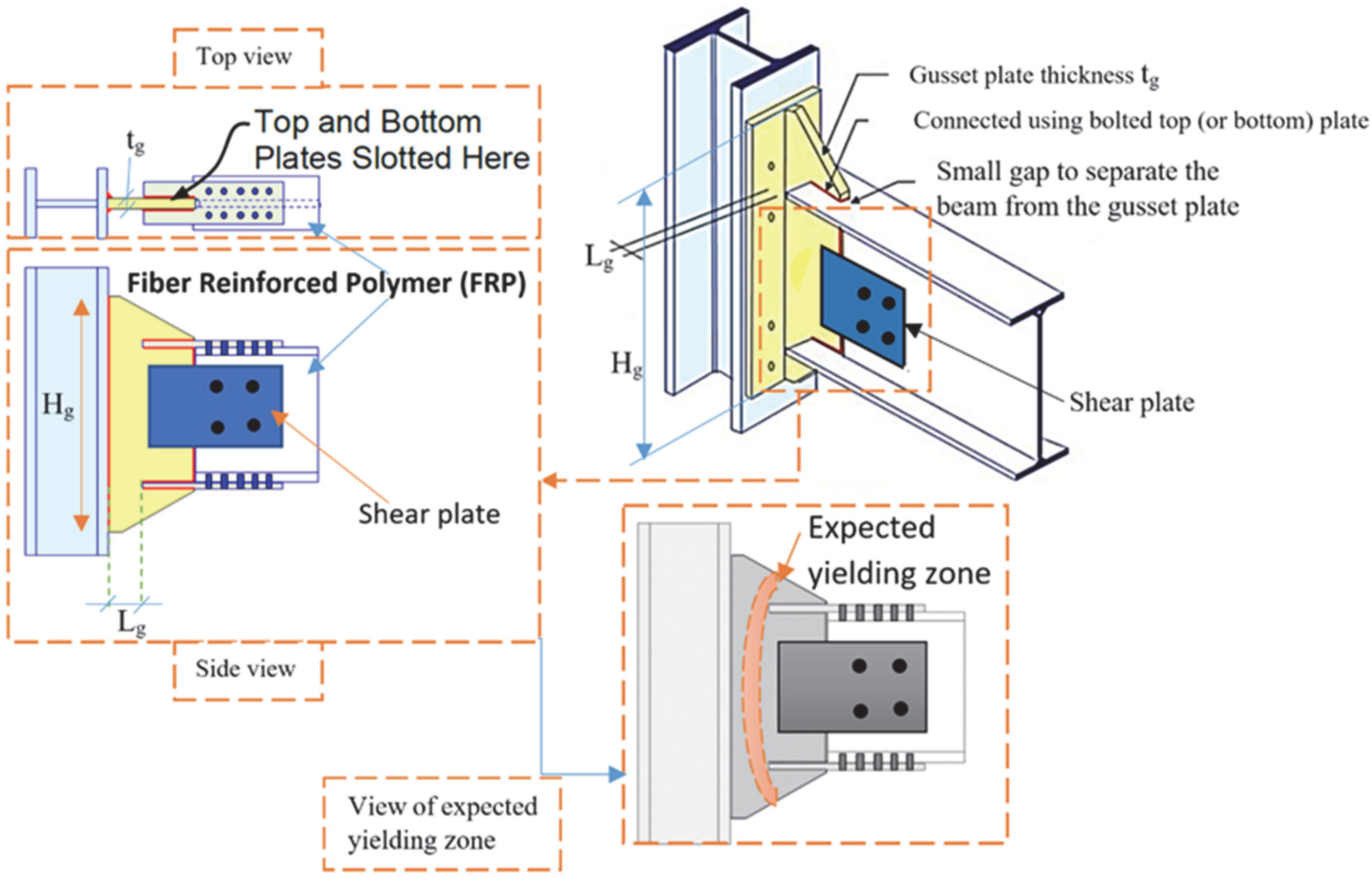
2. The Proposed Connection

As Fiber-Reinforced Polymer (FRP) profile sections possess high elastic strength but lack the ability to undergo nonlinear deformation, they exhibit brittle behavior when used as moment-resisting frame (MRF) systems. Accordingly, they cannot serve as the main ductile elements in structures subjected to seismic loads. To address this limitation, an innovative type of steel moment connection is proposed in this paper. This connection utilizes the ductile yielding of gusset plates as the primary source of rotational ductility. The concept behind this connection is that the ductility demand is concentrated in the connection itself, which is therefore considered the critical component. The beam and column are expected to remain elastic, allowing the significant advantages of FRP profile sections to be fully exploited. Combining FRP members with the steel gusset plate connection shown in Figure 3 presents a promising solution. In this configuration, the high strength and stiffness of the FRP beam and column are maintained, while the lack of ductility is compensated for by the yielding behavior of the gusset plate. In the proposed moment connection, the beam is intentionally cut short, leaving a gap from the column face. As a result, yielding and plastic hinge formation are expected to occur primarily through the in-plane deformation of the gusset plate. The gusset plate is connected to the column face using bolts and an end plate. The main features and benefits of the proposed gusset plate connection in the FRP moment-resisting frame are summarized as follows: (a) A plastic hinge forms in the gusset plate, providing sufficient strength, rotational stiffness, and ductility, which allows the FRP elements to remain elastic. (b) The strong-column–weak-beam criterion does not need to be satisfied. Instead, a “strong frame (strong beam and strong column)–weak gusset” criterion should be adopted to ensure that the plastic hinge forms and remains in the gusset plate, while the column, beam, bolts, and connection components remain essentially elastic. (c) Continuity plates in the column are generally not required, as there is no direct connection between the beam flange and the column flange. This reduces the risk of local deformation, flange crippling, and web buckling. (d) Column web doubler plates are not needed in most cases since, with the “strong frame–weak gusset” design philosophy, yielding in the column web is very limited. (e) The beam does not need to be compact with a b/t ratio of “high ductility” since the beam is designed to remain essentially elastic. These advantages can lead to a reduction in construction costs for structures built using FRP beams and columns combined with the proposed steel gusset plate connection.
To determine the required gusset plate plastic hinge capacity, based on the Ref [26] studies, a slot in the beam flange is needed to connect the beam to the gusset plate in the field. The required plastic section modulus of the gusset plate should be determined by Equation (1):
Z g = 0.9 R y b F y b Z b C p r g R y g F y g     0.75 R t b F u b Z n b C p r g R y g F y g
where R y b ,   R t b , and R y g are, respectively, the expected yield strength factor of the beam, the expected ultimate strength factor of the beam, and the expected yield strength factor of the gusset plate. Also, F y g , F y b , and F u b are the yield strength of the gusset plate, the yield strength of the beam, and the ultimate strength of the beam. Moreover, the strain-hardening factor of the gusset plate is determined as C p r g = F u g + F y g 2 F y g . Also, Znb is the plastic section modulus of the beam at the net section:
Z n b = Z b t g t b f . d b t b f
where Zb ,   t g ,   t b f , and d b are the gross plastic section modulus of the beam, the thickness of the gusset plate, the thickness of the flange beam, and the height of the beam.
The height of the gusset plate, Hg1, is calculated as
H g = 4 Z g t g
H g 1 must satisfy the architectural limitation.

3. Numerical Study

3.1. Finite Element Simulation

To simulate finite element (FE) models, ANSYS v.17.0 software was used. In this regard, element Shell-181 was used to model all steel and FRP components. Considering that the bolts are assumed to prevent any slippage in the connection, and for the sake of modeling simplicity, the nodes were merged after meshing these components. Therefore, although the bolts were not modeled, their effect has been taken into account. In the vicinity of the connection, a smaller mesh was used. Accordingly, the models were meshed using 3625 elements.

3.2. Verification of FE Simulation

To validate the results of finite element modeling, a laboratory test reported by Qureshi [27] was used, as its conditions are similar to the subject of this paper. In this laboratory test, FRP beams and FRP columns were connected using steel connections. Therefore, its nature is close to the subject of this paper, although the concepts are not identical. Figure 4 shows the geometry of the laboratory model. Material specifications as well as boundary conditions were modeled in the software according to the test conditions. A comparison of the results in Figure 4 indicates a good agreement between the numerical and experimental results. The left and right curves in Figure 4b represent the comparison of the FE results and the experimental test results under applied upward loading (which creates a positive moment at the support) and downward loading (which creates a negative moment at the support), respectively. The FE and test results in the elastic zone coincide with an error of less than 2%, whereas in the nonlinear zone, the error is around 7%, which is acceptable and indicates high-quality correlation. Therefore, with the confidence of numerical modeling, the models addressed in this paper are modeled and analyzed.

3.3. Models

As mentioned before, the FRP profile sections have great strength and stiffness without the capability to experience suitable ductility to energy imposed by dissipation. Subsequently, to consider the behavior of the connection compound of the steel gusset plate and FRP elements (beam and columns), a finite element (FE) simulation was used. To this end, variables such as λ g = L g t g , λ h = H g t g were defined to take into consideration their effect on the behavior of connection. λ g and λ h represent the slenderness of the gusset plate in relation to its length and height, respectively. First, a benchmark gusset plate with t g = 16   m m was designed. In this section, the height and length of the gusset plate were designed to be 381 mm and 508 mm, respectively. Based on the limitations in selecting the gusset plate and FRP profile sections, an I-shaped FRP section of 10   ×   10   ×   3 / 8 ( 254   ×   254   ×   9.52   m m ) was used. In the FRP section, the same height and flange dimensions were applied. To evaluate the effect of the defined slenderness ratios, λ g and λ h , while keeping the geometry constant, gusset plates with t g = 8   m m ,   16   m m ,   a n d   24   m m were considered. These different t g values resulted in λ h = 47.62 ,   23.81   a n d   15.87 , respectively. In addition, the distance between the column face and beam flange was considered to be 0.25 h b ,   0.5 h b ,   a n d   h b , where h b   is the height of the beam section. This produces different λ g values corresponding to each t g .

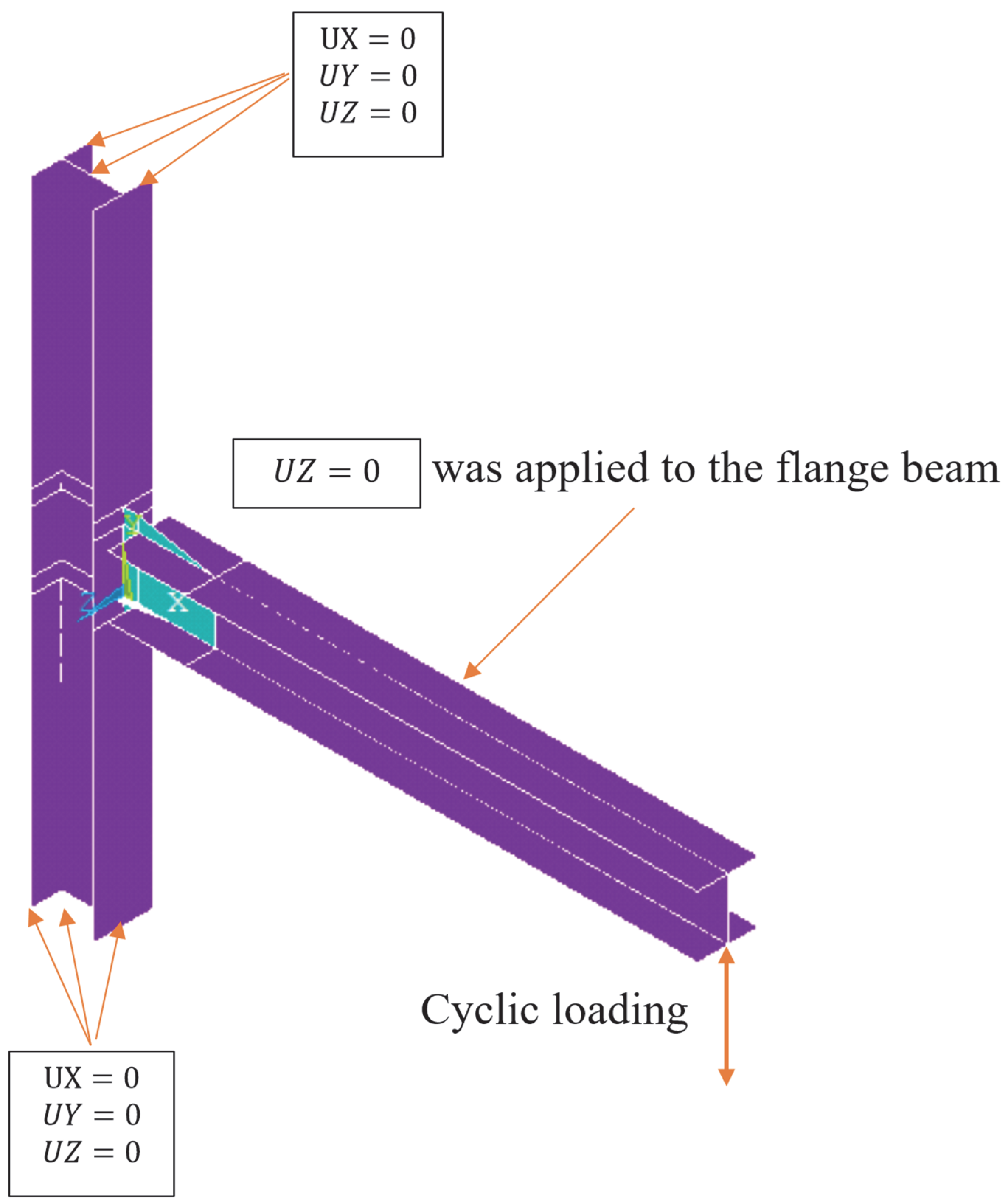
3.4. Boundary Condition and Materials

To evaluate the behavior of the FE models, a boundary condition was applied as shown in Figure 5. This boundary condition represents a moment-resisting frame in which the moment frame at the middle of the beam and columns is zero. Additionally, cyclic loading was applied at the end of the beam. To achieve this, the loading was applied as y ,   2 y ,   3 y ,   4   and repeated up to a rotation of 0.04 rad.
The material properties of the FRP were obtained from the website www.roechling.com/industrial/products/composites/gfrp-cfrp/composite-profiles (1 March 2025) and are listed in Table 1. Accordingly, for the FE models used in this paper, a tensile strength of 2400 MPa, tensile modulus of 245,000 MPa, and modulus of elasticity of 200 GPa were used. For steel plates, the yielding stress, ultimate strength, and modulus of elasticity were taken to be 240 MPa, 370 MPa, and 200 GPa, respectively.

4. Results and Discussion

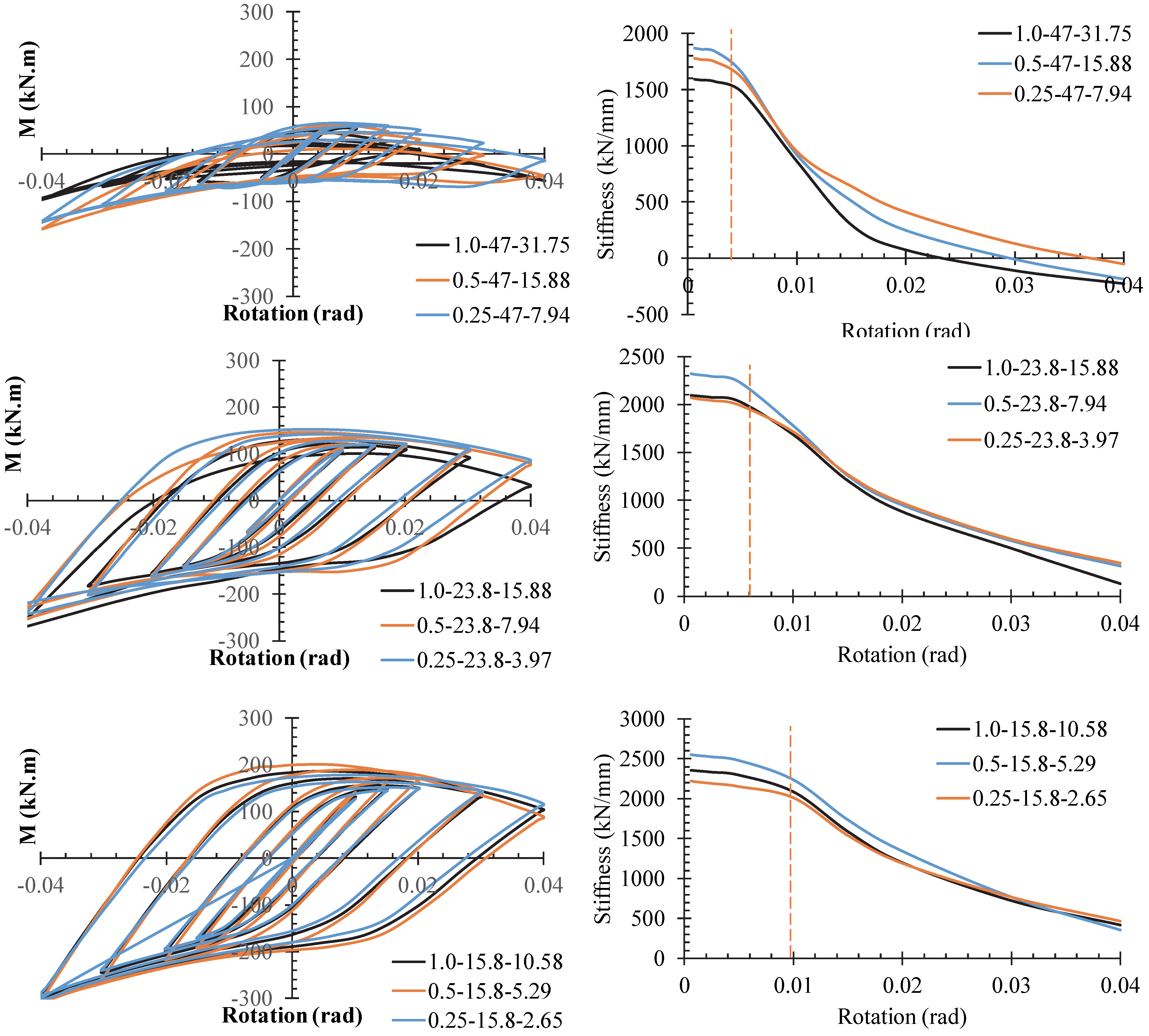
4.1. Hysteresis Curves

The hysteresis curves of the FE models are plotted in Figure 6. The hysteresis curve of any structure contains valuable information regarding its performance. Structural parameters are derived based on the hysteresis curve. Overall, the hysteresis curve provides insight into the performance of the system. In reference to the Figure, no pinching is seen in these curves. As depicted, all models dissipate energy up to a rotation of 0.04 rad without degradation in stiffness or strength. This energy is dissipated though plastic hinge formation in the steel gusset plates, since FRP profile sections exhibit elastic performance. Consequently, this connection is able to be used as a ductile fuse when FRP profile sections are employed. Additionally, increasing the thickness of the gusset connection improves the behavior of the system (in terms of strength, energy dissipation, and stiffness), as will be discussed in the subsequent sections.

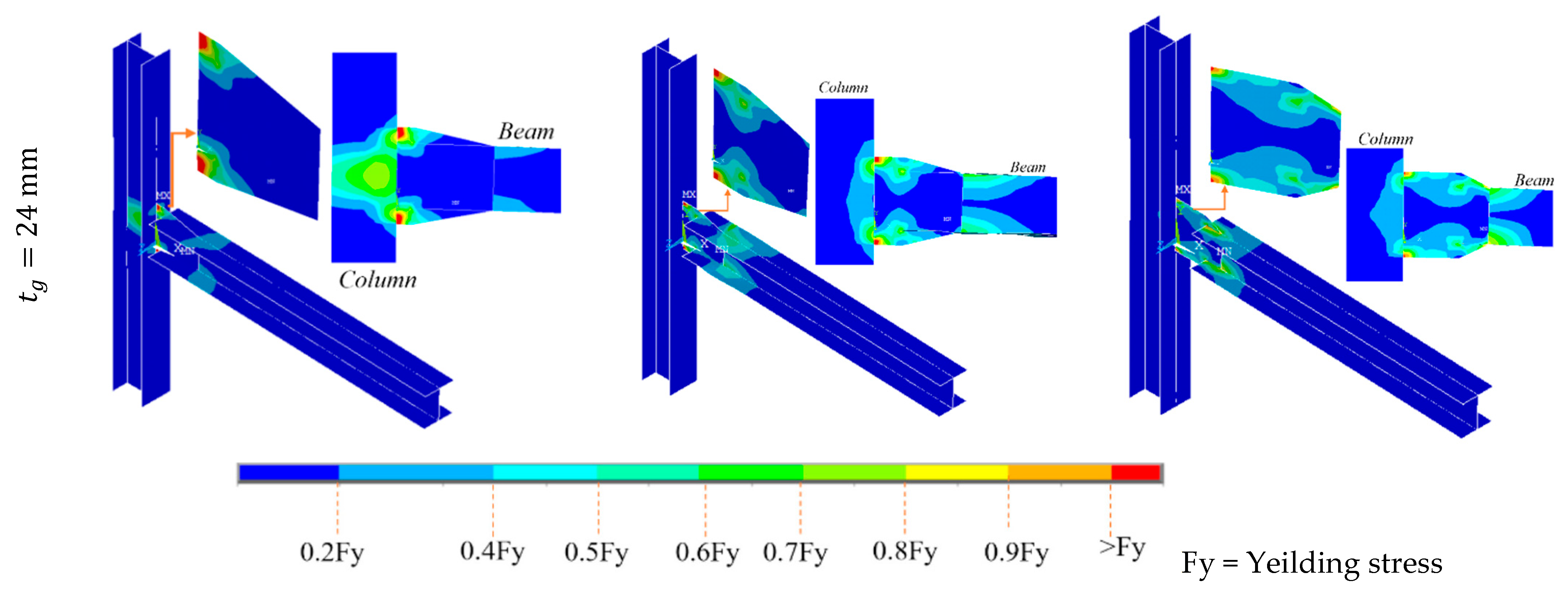
4.2. Yielding Status of the Models

One of the most important roles of the proposed connection is that it is expected to confine yielding within the gusset connection (as a ductile fuse), while the FRP connection (as a brittle element in this system) remains essentially elastic. Therefore, the yielding status corresponding to a rotation of 0.04 rad is shown in Figure 7. In models with a slenderness ratio of λ h 23 , the stress in the beam and column is low, and they remain essentially elastic. However, for λ h < 23 , yield stress is concentrated only in the corners of the gusset plate connection at the interface with the column and does not develop fully in the gusset plate. This leads to an increase in stress in the beam and column. In this situation, the lower the value of L g , the more critical the stress concentration becomes. Therefore, the use of such a gusset plate is not recommended, as it may cause the beam to fracture.
Although yielding is concentrated in the gusset plate, buckling is also evident. Therefore, it is suggested that the sheet thickness be selected such that its slenderness ratio is not less than λ h < 47 . To achieve optimal yielding, it is suggested that connections meeting the conditions outlined below be used. This limitation is proposed to ensure distributed yielding across the gusset plate.
L g 0.5 h b ,
16 < λ h < 47 ,
4 < λ g < 16 ,

4.3. The Effect λ g on System Performance

As shown in Figure 8, different L g values can be used, resulting in different slenderness ratios λ g = L g t g . In this section, the effect of λ g on the behavior of the connections is considered. Accordingly, Figure 8 compares the hysteresis curves and stiffness versus rotation of models with the same sections but different λ g values. As shown in the Figure, with λ h kept constant, a reduction in λ g leads to a reduction in the hysteresis curve’s area. The capacity and elastic stiffness of the models are listed in Table 2. For models with λ h = 47.62   a n d   23.81 , increasing λ g from 63.5 ( 0.25 h b ) to 127 ( 0.5 h b ) and 254 ( h b ) results in a capacity reduction of 4% to 10% and 3% to 7%, respectively. However, when λ h < 23.81 , increasing λ g does not reduce Mu but instead improves it by 13%. Additionally, increasing λ g enhances elastic stiffness. This indicates that the connection behavior is influenced by both λ g and λ h . This trend is confirmed by the hysteresis curves plotted in Figure 9. In this comparison, models with the same λ g but different λ h values have been used.

4.4. The Effect of λ h = h t g on System Performance

In Figure 10, the hysteresis curves and skeleton curves of models with the same λ g but different λ h values are compared. The results derived from these curves are listed in Table 3. This Figure indicates that λ h has a considerable effect on the results. Using a greater λ h value results in lower capacity, stiffness, and energy dissipation. For models with λ h = 7.94 , undesirable performance is observed. In this case, the strength of the connection tends to dwindle at a rotation of approximately 0.0025 rad. Therefore, models with λ h < 7.94 are recommended. The results listed in Table 3 also confirm that by reducing λ h from 47.62 to 23.81 or 15.87, the capacity is improved by more than 2.0 times. Additionally, the elastic stiffness is improved by a factor of 1.16 to 1.48.

4.5. Energy Absorption and Equivalent Damping Ratio

Two important seismic parameters, energy abortion, E, and the equivalent damping ratio, ζ , are considered in this section. E is calculated as the area enclosed by the load–displacement curves of the models. The equivalent damping ratio, ζ , is obtained by equating the measured energy dissipated per cycle (ED) in the experiment to that of a viscously damped oscillator [28]. It can be expressed by
ζ = 1 4 π E D E S 0 ,
where E S 0 is the energy stored in an elastic zone, shown in Figure 11.
The energy dissipated in a cycle, used to calculate the damping ratio versus rotation, is plotted in Figure 12. As shown in this Figure, models with λ h = 47.62 exhibit a greater ζ up to a rotation of 0.01. However, after a rotation of 0.01, ζ drops suddenly due to the buckling of the gusset plate. When λ g = h b , models with λ h = 23.81 demonstrate a better ζ than other models. Therefore, to achieve optimal ζ , it is recommended that λ g h b and 47.61 < λ h < 15.87 be used.
Also, with an increase in λ h , E is reduced. Accordingly, models with λ h = 47.62 show low energy dissipation capacity. Although the E value of models with λ h = 15.87 is greater than that of models with λ h = 23.81 , their energy capacity up to a rotation of 0.03 rad is close. In reference to Table 4, with an increase in h g from h b to 0.25 h b , E is reduced by 23% to 53%, while λ h < 15.87 . However, with a reduction in λ h from 47.62 to 15.87, E is enhanced by a factor between 3.36 and 9.63, which is considerable. Therefore, the impact of λ h is greater than that of λ g . This also confirms the limitations expressed in Equations (4)–(6).

5. Conclusions

This paper describes the development of gusset plate connections for FRP sections used as beams and columns. The results indicated that although FRP profile sections cannot provide ductility, energy dissipation capacity is achieved through the yielding of the gusset plate. The proposed connection was evaluated, and the results are summarized as follows:
  • All models offered a rotation capacity of 0.04 rad, confirming the ability of the connection to be used as a ductile fuse. Since FRP sections are unable to experience nonlinear behavior, it is important that the connection acts as a ductile fuse without fracture.
  • For models with a slenderness ratio of λ h 23 , the beam and column experience low stress and remain largely elastic. However, when λ h < 23 , yield stress concentrates solely at the corners of the gusset plate connection to the column, without developing in the gusset plate itself.
  • Increasing λ h reduces energy dissipation (E). Models with λ h = 47.62 exhibit low energy dissipation capacity. Although models with λ h = 15.87 have greater E than those with λ h = 23.81 , their energy capacities are similar up to a rotation of 0.03 rad.
  • To ensure optimal yielding, it is recommended to select a sheet thickness such that the slenderness ratio satisfies 16 < λ h < 47 , 4 < λ g < 16 , and L g 0.5 h b .
  • In models with λ h = 47.62   a n d   23.81 , increasing λ g from 63.5 to 127 and 254 reduces capacity by 4% to 10% and 3% to 7%, respectively. Conversely, when λ h < 23.81 , increasing λ g not only prevents a reduction in Mu but also enhances it by 13%, while also improving elastic stiffness. Thus, behavior is influenced by both λ g and λ h .

Author Contributions

Conceptualization, A.G. and C.T.; methodology, A.G. and C.T.; software, A.G. and C.T.; validation, A.G., C.T. and A.G.Z.; formal analysis, A.G.Z. and V.K.K.; investigation, A.G., C.T., A.G.Z. and V.K.K.; resources, A.G. and V.K.K.; data curation, A.G., C.T. and A.G.Z.; writing—original draft preparation, A.G. and C.T.; writing—review and editing, A.G.Z. and V.K.K.; visualization, A.G., C.T., A.G.Z. and V.K.K. All authors have read and agreed to the published version of the manuscript.

Funding

This research received no external funding.

Data Availability Statement

The data supporting the findings of this study are available from the corresponding author upon reasonable request.

Conflicts of Interest

The authors declare no conflicts of interest.

References

  1. Attarchian, N.; Aghamohammadi, R.; Nasrollahzadeh, K. Reliability-Based Calibration of Strength-Reduction Factors for Flexural Design of FRP-RC Beams Under Various Load Combinations. J. Compos. Sci. 2025, 9, 154. [Google Scholar] [CrossRef]
  2. Uyttersprot, J.; De Corte, W.; Van Paepegem, W. Mechanical Characterization of GFRP Tiled Laminates for Structural Engineering Applications: Stiffness, Strength and Failure Mechanisms. J. Compos. Sci. 2024, 8, 265. [Google Scholar] [CrossRef]
  3. Qureshi, J. A Review of Fibre Reinforced Polymer Structures. Fibers 2022, 10, 27. [Google Scholar] [CrossRef]
  4. Harati Khalilabad, E.; Ruiz Emparanza, A.; De Caso, F.; Roghani, H.; Khodadadi, N.; Nanni, A. Characterization Specifications for FRP Pultruded Materials: From Constituents to Pultruded Profiles. Fibers 2023, 11, 93. [Google Scholar] [CrossRef]
  5. Creative Composites Group. University of Arizona Cooling Tower 2022. Available online: https://www.creativecompositesgroup.com/resources/case-studies/cooling-tower (accessed on 12 October 2022).
  6. Keller, T.; Nikolaos, A.T.; Anastasios, P.V.; de Castro, J. Effect of natural weathering on durability of pultruded glass fiber–reinforced ridge and building structures. J. Compos. Constr. 2016, 20, 4015025. [Google Scholar] [CrossRef]
  7. Jones, R.M. Mechanics of Composite Materials; CRC Press: Boca Raton, FL, USA, 2018. [Google Scholar]
  8. Bank, L.C. Composites for Construction: Structural Design with FRP Materials; John Wiley Sons: Hoboken, NJ, USA, 2006. [Google Scholar]
  9. Mosallam, A.S. Applications of FRP composites in civil engineering: A review. Struct. Eng. Int. 2016, 26, 356–366. [Google Scholar]
  10. Hollaway, L.C. A review of the present and future utilization of FRP composites in the civil infrastructure. Constr. Build. Mater. 2010, 24, 2419–2445. [Google Scholar] [CrossRef]
  11. Nanni, A. FRP composites in civil engineering: Advances and challenges. In Proceedings of the CICE 2012 Conference, Rome, Italy, 18–21 June 2012. [Google Scholar]
  12. Teng, J.G.; Yu, T.; Fernando, D. Strengthening of Steel Structures with Fiber-Reinforced Polymer Composites. J. Constr. Steel Res. 2012, 78, 131–143. [Google Scholar] [CrossRef]
  13. ACI Committee 440. Guide for the Design and Construction of Structural Concrete Reinforced with FRP Bars. American Concrete Institute. 2022. Available online: https://basalt-fibers.com/wp-content/uploads/2021/05/Standart_ACI-4401R15.pdf (accessed on 1 March 2025).
  14. McGregor, J.W.; Laffey, R.J. Assessment of the Brittleness of Fiber Reinforced Polymers in Structural Applications. Mater. Res. Express 2019, 6, 085601. [Google Scholar]
  15. Biscaia, H.C.; Chastre, C. Design method and verification of steel plate anchorages for FRP-to-concrete bonded interfaces. Compos. Struct. 2018, 192, 52–66. [Google Scholar] [CrossRef]
  16. Tafsirojjaman, T.; Dogar, A.U.R.; Liu, Y.; Manalo, A.; Thambiratnam, D.P. Performance and design of steel structures reinforced with FRP composites: A state-of-the-art review. Eng. Fail. Anal. 2022, 138, 106371. [Google Scholar] [CrossRef]
  17. Sharma, R.; Kaur, S. Analyzing the Mechanical Properties of Fiber Reinforced Polymers. J. Compos. Mater. 2023, 57, 651–661. [Google Scholar]
  18. Ju, M.; Park, K.; Park, C. Punching Shear Behavior of Two-Way Concrete Slabs Reinforced with Glass-Fiber-Reinforced Polymer (GFRP) Bars. Polymers 2018, 10, 893. [Google Scholar] [CrossRef] [PubMed]
  19. Alma, M.; Chen, Y. Durability of Fiber Reinforced Polymers (FRP) in Structural Applications. J. Mater. Civ. Eng. 2004, 16, 421–426. [Google Scholar]
  20. Mao, F.; Zhang, Z. Thermal and Electrical Properties of Polymer Composites. J. Compos. Sci. 2021, 5, 25–40. [Google Scholar]
  21. Badran, A.I.; Farhan, M. Evaluation of the Properties and Applications of Fiber-Reinforced Polymer Composites in Civil Engineering. Adv. Mater. Res. 2015, 104–105, 185–190. [Google Scholar]
  22. Harris, J.R.; Zia, A.A. Design Principles for Fiber Reinforced Composites in Engineering Applications. Compos. Sci. Technol. 2018, 170, 70–85. [Google Scholar]
  23. Bakharev, T.; Mazzolani, F.M. FRP Composites in Modern Bridge Construction. J. Bridge Eng. 2005, 10, 377–386. [Google Scholar]
  24. Biondi, F.; Armuelles, J. Smart Fiber-Reinforced Polymers for Structural Engineering Applications. J. Smart Struct. Syst. 2023, 27, 1–12. [Google Scholar]
  25. Ascione, F.; D’Aniello, M.; Feo, L.; Granata, L.; Landolfo, R. A novel ductile connection for FRP pultruded beam-to-column assemblies. Compos. Struct. 2024, 337, 118091. [Google Scholar] [CrossRef]
  26. Qian, X.; Astaneh-Asl, A. Development of a New Steel Moment Connection. In Proceedings of the World Congress on Civil, Structural, and Environmental Engineering (CSEE’16), Prague, Czech Republic, 30–31 March 2016. [Google Scholar] [CrossRef]
  27. Qureshi, J.; Nadir, Y.; John, S.K. Cyclic Response of Bolted and Hybrid Pultruded FRP Beam-Column Joints between I-Shaped Sections. Fibers 2021, 9, 66. [Google Scholar] [CrossRef]
  28. Chana, R.; Albermania, F. Experimental study of steel slit damper for passive energy dissipation. Eng. Struct. 2008, 30, 1058–1066. [Google Scholar] [CrossRef]
Figure 1. Market share of Fiber-Reinforced Polymers (FRPs) by application [3].
Jcs 09 00280 g001
Figure 2. Application of FRP profile sections: (a) composite pedestrian bridge in Bermuda [4]; (b) FRP profiles on the façade of a building on the University College Ghent’s Schoonmeersen Campus (Source: Open Oproep 2013); (c) a University of Arizona Cooling Tower using pultruded glass FRP [5]; (d) the Eyecatcher five-story FRP-framed building in Basel, Switzerland [6].
Jcs 09 00280 g002
Figure 3. Proposed connection for FRP moment-resisting frames.
Jcs 09 00280 g003
Figure 4. Verification of test: (a) dimensions of test specimen reported in Ref. [27] and (b) comparison between FE results and test results.
Jcs 09 00280 g004
Figure 5. Boundary condition.
Jcs 09 00280 g005
Figure 6. Hysteresis curves.
Jcs 09 00280 g006
Figure 7. The yielding statuses of the FE models.
Jcs 09 00280 g007aJcs 09 00280 g007b
Figure 8. Hysteresis curves and stiffness in the case of comparing λ g values.
Jcs 09 00280 g008
Figure 9. Comparing hysteresis curves with the same λ g .
Jcs 09 00280 g009
Figure 10. Comparing the hysteresis and skeleton curves in the case of the same λ g .
Jcs 09 00280 g010
Figure 11. Effective stiffness and energy dissipated in a cycle to calculate the damping ratio.
Jcs 09 00280 g011
Figure 12. Comparing energy abortion and equivalent damping ratio.
Jcs 09 00280 g012
Table 1. Properties of FRP reported on www.roechling.com/industrial/products/composites/gfrp-cfrp/composite-profiles (1 March 2025).
Technical Values
Durostone® CF Profiles
UnitValue
Bending strengthN/mm2850–1400
Bending modulusN/mm270,000–130,000
Tensile strengthN/mm2900–2500
Tensile modulusN/mm288,000–245,000
Compression strengthN/mm2120–420
Impact strengthkJ/m290–240
Water absorption%0.01–0.2
Table 2. Ultimate capacity and stiffness in the case of comparing λ g values.
Models L g
(mm)
t g
(mm)
λ g λ h Mu *
(kN.m)
K **
(kN/mm)
m o d e l i m o d e l 0.25 h b
Mu K
0.25-47-7.9463.5 ( 0.25 h b )87.9447.6224,0381779.49
0.5-47-15.88127 ( 0.5 h b )815.8847.6223,041.31869.330.961.05
1.0-47-31.75254 ( h b )831.7547.6221,550.51590.660.900.89
0.25-23.8-3.9763.5 ( 0.25 h b )163.9723.8148,699.62072.40
0.5-23.8-7.94127 ( 0.5 h b )167.9423.8147,481.62320.200.971.12
1.0-23.8-15.88254 ( h b )1615.8823.8145,082.42094.230.931.01
0.25-15.8-2.6563.5 ( 0.25 h b )242.6515.8759,659.42222.73
0.5-15.8-5.29127 ( 0.5 h b )245.2915.8767,204.82554.541.131.15
1.0-15.8-10.58254 ( h b )2410.5815.8759,934.42355.041.001.06
* Mu = bending moment capacity; ** K = initial stiffness (kN/mm), calculated as the ratio of vertical load to vertical displacement.
Table 3. Comparing the hysteresis and skeleton curves in the case of the same λ g .
Models L g
(mm)
t g
(mm)
λ g λ h Mu *
(kN.m)
K **
(kN/mm)
m o d e l i m o d e l t = 8
Mu K
0.25-47-7.9463.5 ( 0.25 h b )87.9447.6224,0381779.49
0.5-47-15.88127 ( 0.5 h b )815.8847.6223,041.31869.33
1.0-47-31.75254 ( h b )831.7547.6221,550.51590.66
0.25-23.8-3.9763.5 ( 0.25 h b )163.9723.8148,699.62072.402.031.16
0.5-23.8-7.94127 ( 0.5 h b )167.9423.8147,481.62320.202.061.24
1.0-23.8-15.88254 ( h b )1615.8823.8145,082.42094.232.091.32
0.25-15.8-2.6563.5 ( 0.25 h b )242.6515.8759,659.42222.732.481.25
0.5-15.8-5.29127 ( 0.5 h b )245.2915.8767,204.82554.542.921.37
1.0-15.8-10.58254 ( h b )2410.5815.8759,934.42355.042.781.48
* Mu = bending moment capacity; ** K = stiffness.
Table 4. Comparing energy dissipation results.
Models L g
(mm)
t g
(mm)
λ g λ h E *
(kN.m)
m o d e l i m o d e l 0.25 h b m o d e l i m o d e l t = 8
0.25-47-7.9463.5 ( 0.25 h b )87.9447.62537.35
0.5-47-15.88127 ( 0.5 h b )815.8847.62358.740.67
1.0-47-31.75254 ( h b )831.7547.62199.860.37
0.25-23.8-3.9763.5 ( 0.25 h b )163.9723.811635.91 3.04
0.5-23.8-7.94127 ( 0.5 h b )167.9423.811540.030.942.87
1.0-23.8-15.88254 ( h b )1615.8823.811258.700.772.77
0.25-15.8-2.6563.5 ( 0.25 h b )242.6515.871807.23 3.36
0.5-15.8-5.29127 ( 0.5 h b )245.2915.872068.221.145.77
1.0-15.8-10.58254 ( h b )2410.5815.871925.041.079.63
* E = energy absorption.
Disclaimer/Publisher’s Note: The statements, opinions and data contained in all publications are solely those of the individual author(s) and contributor(s) and not of MDPI and/or the editor(s). MDPI and/or the editor(s) disclaim responsibility for any injury to people or property resulting from any ideas, methods, instructions or products referred to in the content.

