Article

Shining a Light on Carbon-Reinforced Polymers: Mg/MgO and TiO2 Nanomodifications for Enhanced Optical Performance

1
Materials Science and Testing of Polymers, Montanuniversitaet Leoben, Otto Glöckel-Straße 2/II, 8700 Leoben, Austria
2
Laboratory for Mechanical Systems Engineering, Swiss Federal Laboratories for Materials Science and Technology, Überlandstrasse 129, 8600 Dübendorf, Switzerland
3
Processing of Composites and Design for Recycling, Montanuniversitaet Leoben, Otto Glöckel-Straße 2/III, 8700 Leoben, Austria
4
Functional Materials and Materials Systems, Montanuniversitaet Leoben, Roseggerstraße 12, 8700 Leoben, Austria
*
Author to whom correspondence should be addressed.
Retired from Empa.
J. Compos. Sci. 2025, 9(4), 187; https://doi.org/10.3390/jcs9040187
Submission received: 13 February 2025 / Revised: 7 April 2025 / Accepted: 8 April 2025 / Published: 12 April 2025
(This article belongs to the Special Issue Carbon Fiber Composites, 4th Edition)

Abstract

:
This study examines the intrinsic optical enhancements of carbon fiber-reinforced polymers (CFRPs) achieved through the integration of magnesium oxide (MgO) nanoparticles, as well as Mg/MgO and titanium dioxide (TiO2) thin films onto carbon fibers. Integration was performed by quasi-continuous electrophoretic deposition (EPD) and physical vapor deposition (PVD), respectively. Employing a customized electrophoretic cell, EPD facilitated uniform MgO nanoparticle deposition onto unsized carbon fibers, ensuring stable nanoparticle dispersion and precise fiber coating. As a result, the fibers exhibited increased ultraviolet (UV) reflectance, largely attributed to the optical properties of the protective MgO layer. In parallel, PVD enabled the deposition of Mg/MgO and TiO2 thin films with tailored thicknesses, providing precise control over key optical parameters such as reflectivity and interference effects. Mg/MgO coatings demonstrated high UV reflectivity, while TiO2 layers, with their varying refractive indices, generated vibrant colors in the visible (Vis) range through thickness-dependent light interference. Scanning electron microscopy (SEM) and atomic force microscopy (AFM) assessed the quality, thickness, and uniformity of these thin films, and UV/Vis spectroscopy confirmed the influence of deposition parameters on the resulting optical performance. Post-lamination analyses revealed that both EPD and PVD modifications significantly enhanced UV reflectivity and allowed for customizable color effects. This dual strategy underscores the potential of combining EPD and PVD to develop advanced CFRPs with superior UV resistance, decorative optical features, and improved environmental stability.

1. Introduction

The effects of adding nanoparticles into polymer matrices of fiber-reinforced polymer (FRP) composites have been investigated for several decades [1,2]. The focus has been on improving mechanical properties, e.g., strength, fatigue, impact and fracture resistance [3,4,5,6,7], durability against exposure to complex service environments [7,8], or providing multifunctional behavior, e.g., self-sensing capability [9,10].
In contrast, the potential of nanoparticle addition to alter the visual or optical appearance of materials has received relatively little attention. Yet, outstanding examples highlight its promise: Vantablack®, which achieves extreme light absorption through an aligned array of carbon nanotubes [11], and fresh snow, which exhibits exceptionally high reflectivity due to multiple scattering within its nano- and micro-scale snow–air structure [12]. These contrasting cases inspired the present investigation into how nanomodification can be used to influence—and potentially tune—the visual appearance and optical reflectance of carbon fiber-reinforced polymer (CFRP) composites.
Traditionally, coatings have played a central role in tailoring the surface appearance and performance of polymer products. Lacquers and similar surface treatments are commonly used to enhance environmental resistance, chemical durability, and mechanical wear protection, while also delivering specific optical qualities such as color, gloss, and texture [13,14,15,16,17,18,19,20,21,22]. These coatings often provide both esthetic value and functional protection from environmental factors like ultraviolet (UV) radiation and moisture [22,23,24,25]. However, conventional lacquers typically rely on volatile organic compounds (VOCs), which pose health risks and contribute to air pollution [26,27,28,29]. In response to these challenges—as well as the growing demand for advanced, sustainable materials—alternative approaches have emerged [30,31]. Among them, the incorporation of nanoparticles or thin films into polymers offers a promising route to finely tune optical behavior while reducing environmental impact [32,33,34].
A wide range of parameters can influence the effect of nanomodification, including the nanoparticle material, size distribution, shape, processing method and conditions, loading concentration, and degree of dispersion, among others. To explore these influences, an initial series of experiments was conducted using nanomodified epoxy resins incorporating carbon black, carbon nanotubes (CNTs), silver (Ag), and silicon dioxide (SiO2) nanoparticles. In parallel, CNTs, Ag, and SiO2 nanoparticles were deposited in varying amounts onto carbon fibers via electrophoretic deposition (EPD), and the modified fibers were subsequently processed into carbon fiber-reinforced polymer (CFRP) composites [33].
All modified specimens were characterized for reflectance in the visual and ultraviolet (UV) wavelength ranges and compared to unmodified references—namely neat epoxy resin, unmodified carbon fibers, and CFRP laminates made from them. Depending on the nanoparticle type and deposition amount, both increases and decreases in reflectance were observed. Notably, SiO2-modified fibers showed enhanced reflectance, particularly in the UV range—up to a hemispherical reflectance value of 16% compared to the corresponding unmodified composite’s reflectance value of 9%. While these changes may have limited impact on visible appearance, the increased UV reflectance suggests potential for mitigating UV-induced degradation in CFRPs through reduced UV absorption.
In a second series of experiments, matrix modification was omitted in favor of direct fiber surface modification. This shift was motivated by several factors: (1) enhancements from nanoparticle-modified epoxy resins are not always fully translated into the final CFRP composite [1]; (2) the maximum nanoparticle loading in epoxy is limited [35]; (3) nanoparticles deposited directly on fibers may not only affect optical appearance, but also enhance interfacial adhesion and reduce interfacial stresses within the composite structure [5].
This second series focused on the surface modification of carbon fibers using two deposition techniques: electrophoretic deposition (EPD) and physical vapor deposition (PVD). Ag and SiO2 nanoparticles were again used as model materials [34]. Here, quasi-continuous EPD as well as PVD was utilized to coat the carbon fibers prior to lamination. The optical experiments showed that Ag applied via PVD increases the reflectance in regard to the film thickness by up to 40% and above in the visible range while SiO2 decreases it with increasing film thickness to slightly below the unmodified laminate values of 8%. Quasi-continuous EPD shows in both cases an increase in UV reflectance to 15% compared to the 9% of the unmodified laminate. The current study builds upon that work, employing EPD and PVD to deposit magnesium oxide (MgO) particles and titanium dioxide (TiO2) thin films, respectively.
MgO nanoparticles have gained significant attention for their potential in enhancing the optical appearance and UV protection of polymers, if applied to the surface or within the polymer part [36]. These nanoscale particles exhibit distinct optical characteristics compared to their bulk counterparts, mainly due to quantum confinement, a large surface-to-volume ratio, the geometry of the nanoparticle, and the presence of surface defects [37,38,39,40]. Consequently, their bandgap can deviate from the bulk value of approximately 7.5 eV–7.8 eV [37,40,41,42,43,44,45]. Their large surface area also promotes strong light scattering and elevated UV reflectivity. However, surface defects like oxygen vacancies can introduce localized absorption sites, potentially reducing efficiency in the visible spectrum [39,46]. MgO thus serves as a potent UV blocker in films, photonic devices, and UV-sensitive coatings. Compared to conventional UV stabilizers like TiO2, it offers broad-spectrum UV absorption, is abundant, and is typically considered to be non-hazardous, making it appealing for environmentally focused industries [22,47]. However, MgO nanoparticle interactions with living organisms are not completely understood yet. Additionally, MgO is prone to forming magnesium hydroxide (Mg(OH)2) due to exposure to moisture in ambient air or in direct contact with water. Investigations show that the UV absorption of Mg(OH)2 is higher compared to MgO but reflectance can still reach up to 30.5% if Mg(OH)2 nanoparticles are incorporated into polyvinylchloride [48,49].
A key challenge is still achieving and maintaining uniform coverage on the fiber surface in CFRPs. An inhomogeneous or varying distribution compromises both optical efficiency and material quality, especially in applications requiring uniform color [33,34].
Addressing this issue, a different strategy for controlling optical properties involves depositing thin films on carbon fibers prior to lamination. Physical vapor deposition (PVD) methods can precisely deposit materials like Mg or TiO2 in a controlled thickness. Magnesium thin films, for instance, can achieve a reflectance of up to 90% in the 200–300 nm UV range. In the visible and infrared regions, the reflectivity of Mg thin films is generally lower compared to the UV region [44]. The surface roughness of Mg thin films can significantly impact their reflectivity, with smoother films typically showing higher reflectivity. However, Mg is prone to oxidation, which can form a thin layer of MgO on the surface. This oxide layer can affect the overall reflectivity, especially as the oxide layer thickens over time [44,50,51,52,53,54].
Also, MgO thin films exhibit high reflectivity in the UV region while effectively maintaining strong reflectance in the visible and near-infrared regions due to their dielectric character and refractive index of roughly 1.7–2.0. Due to the MgO thin films’ high reflectivity and their being more chemically stable than pure Mg, these films are used in applications such as protective coatings, optical mirrors, and dielectric layers in electronic devices [44,55]. In summary, both Mg and MgO thin films offer high reflectivity in the UV region, with MgO providing broader spectral coverage and better environmental stability [44,50,51,52,53,54,55,56].
TiO2, with its high refractive index (2.5 to 2.9 for the rutile phase and 2.2 to 2.5 for the anatase phase), is particularly effective in manipulating light through interference effects [57]. These interference phenomena can be tailored by adjusting film thicknesses, enabling control over reflectance, transmittance, and scattering [58,59,60,61,62,63]. Additionally, the phase composition of TiO2 containing rutile and/or anatase further influences the degree of light manipulation. In applications where optical performance must remain consistent from various viewing angles, the angular dependence of TiO2-based systems becomes critical. Slight changes in the angle of incidence can alter path lengths through the material, shifting interference maxima or minima and affecting overall reflectivity and color. Consequently, precise engineering of layer thickness, particle geometry, and refractive index gradients is often employed to mitigate or exploit angle-dependent effects [62,63,64]. This level of control is essential in coatings for architectural glass, optical devices, and consumer products, if seeking to maintain uniform appearance or functionality under varying illumination and viewing conditions.
In addition to characterizing the reflectance of CFRP laminates fabricated with MgO- and TiO2-modified fibers, ongoing experiments are being conducted to assess the adhesion strength of nanoparticles and thin films on carbon fiber surfaces using atomic force microscopy (AFM) scratching and nanoindentation techniques. Quasi-static fracture tests on the resulting CFRP laminates are also underway. Preliminary results are available and will be published separately once the full dataset has been analyzed.

2. Materials and Methods

Unsized AS4 HexTow® 12k carbon fibers (obtained from Hexcel Corporation, Stamford, CT, USA) were employed in this study. Raman spectroscopy and thermogravimetric analysis confirmed the absence of any sizing agents on the fibers.

2.1. EPD Modified Carbon Fibers

MgO nanoparticles (purchased from Sigma Aldrich, BET size ≤ 50 nm) were utilized in a quasi-continuous electrophoretic deposition (EPD) process for fiber modification. This process was conducted in a custom-designed EPD apparatus incorporating a winding mechanism, a carbon fiber spool holder, a spreading unit, and three idler pulleys to guide the fiber through a glass vessel containing the nanoparticle suspension (schematic shown in Figure 1). Two metal plates served as electrodes, while a third plate, integrated into the winding system, pulled the fiber through the cell. A gap of 7 mm was consistently maintained between the carbon fiber and the electrodes. The fiber-pulling mechanism is powered by an electric motor that drives the rotating third metal plate, which actively pulls the fiber to produce a dense layup. Prior to use, the pulling plate was coated with a release agent to facilitate the easy removal of the manufactured laminate after processing. In addition to this rotational action, the mechanism can be actuated along the z-axis, allowing for the precise adjustment of the fiber layup density. The entire system is controlled by an Arduino microcontroller, programmed in Visual Studio 2017 and connected via Ethernet. This setup ensures synchronized coordination between the rotation of the metal plate, the fiber feed rate, and the z-axis movement, thereby maintaining consistent and accurate fabrication parameters throughout the process. During the quasi-continuous EPD, a direct current power supply establishes an electric field between the continuously fed carbon fiber and the steel plates serving as electrodes, promoting the deposition of MgO nanoparticles onto the fiber. A 1% nanoparticle suspension, prepared by dispersing 20 g of MgO in 2 L of water, is contained in a glass vessel. The MgO nanoparticles are likely to form with the water Mg(OH)2 with high probability. This suspension undergoes pulse-sonication in two 3 h sessions with a total energy input of 127 kJ, with a 2 h cooling interval between sessions to prevent overheating. The fiber is immersed in the nanoparticle suspension for 1 min at an applied voltage of 20 V, enabling controlled particle deposition. The pH of the nanoparticle suspension was measured to be 10.3 before the deposition process and increased after applying the voltage to about 10.5. The isoelectric point and the point of zero charge for an aqueous MgO nanoparticle suspension is documented in the literature to be at pH values of 12 to 13, leading to the assumption of there being a positive charge on the nanoparticle surface or having a positive zeta potential [65,66,67,68]. Therefore, the anode of the power supply was connected to the carbon fiber, while the cathode was attached on the steel plates, which were submerged in the nanoparticle suspension. Hydrogen evolution, observed as minor bubbling on the carbon fiber surface due to localized pH increases, did occur; however, the use of a bath sonicator significantly minimized this effect by promoting pH uniformity and enhancing mass transport within the suspension. To assess nanoparticle coverage on the fibers, they were dried at 60 °C for several hours after EPD.

2.2. PVD-Modified Carbon Fibers

Additionally, this study utilized PVD technology to modify the optical properties of CFRPs. The carbon fibers were carefully wound by hand around a steel plate (5 cm × 5 cm × 0.2 cm) for Mg deposition and an aluminum stripe (45 cm × 5 cm × 0.1 cm) for TiO2 deposition in two layers, ensuring an even and consistent wrapping to prevent surface irregularities. The prepared setup was then placed in the chosen vacuum chamber of the PVD system for each coating process. To assert film thicknesses or the deposition rate, partly Kapton® tape-sealed silicon wafers were placed next to the carbon fiber samples (Figure 2).

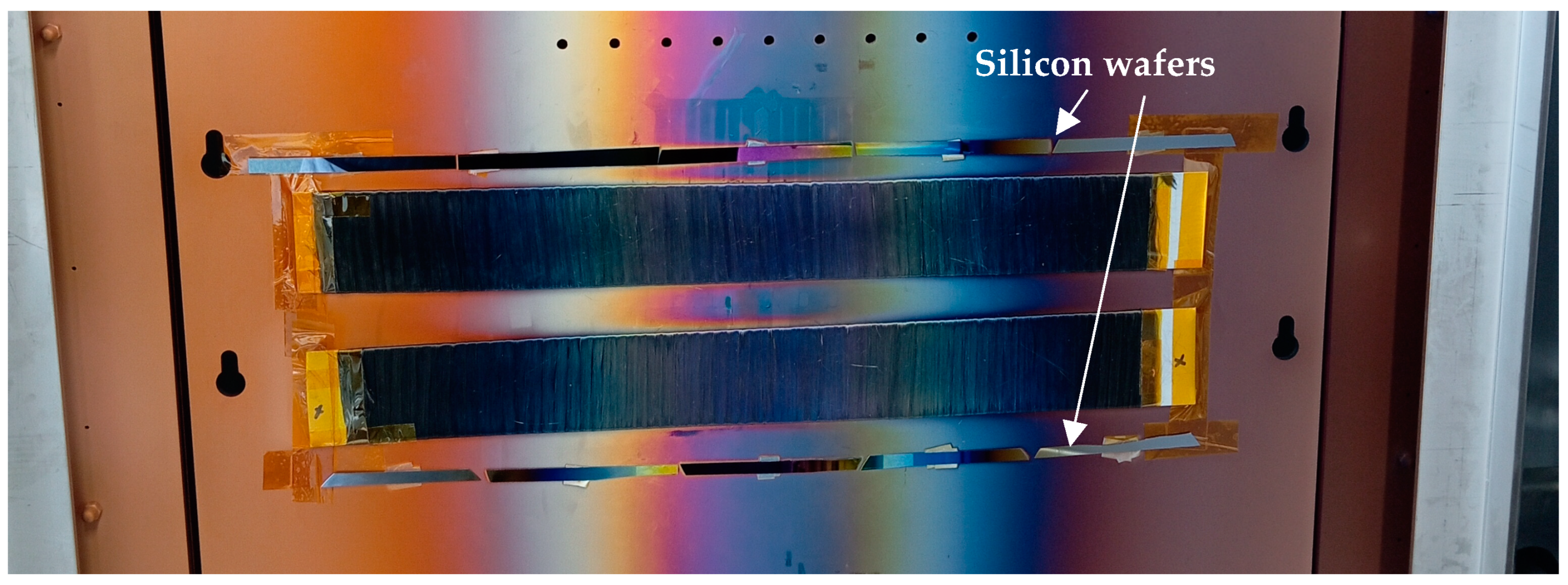
2.2.1. Mg Film Deposition

A DC magnetron sputtering system, designed for laboratory use, was utilized to apply thin films with precise thicknesses onto the carbon fibers. Mg was deposited in the following thicknesses: 10 nm, 20 nm, 50 nm, 250 nm, and 500 nm. The Mg target possessing 99.99% purity and dimensions of Ø 50.8 × 6 mm was obtained from J. Lesker, USA and mounted on an unbalanced AJA A320-XP magnetron with a target-to-substrate distance of approximately 40 mm. Prior to deposition, the target was pre-sputtered to eliminate surface contaminants, and the chamber was evacuated to 9 × 10⁻⁶ mbar base pressure. The argon (Ar) flow rate was maintained at 30 sccm during deposition, resulting in a pressure of 3 × 10⁻³ mbar. The sputter current was consistently held at 0.15 A, with deposition times of 15 s, 30 s, 75 s, 340 s, and 681 s to achieve film thicknesses of approximately 10 nm, 20 nm, 50 nm, 250 nm, and 500 nm, respectively. The sputtering rate was determined in preliminary experiments and calculated to be about 0.73 nm/s.

2.2.2. TiO2 Film Deposition

To deposit TiO2 onto carbon fibers with various film thicknesses by PVD, a FHR.Line.600-V system from FHR Anlagenbau GmbH (Ottendorf-Okrilla, Germany) was utilized to perform reactive DC sputtering. The Ti-target was supplied from Sindlhauser Materials GmbH, Germany and had a purity of 99.9%. This system comprises a load lock chamber and a combined pre-treatment/coating chamber, which features a planar magnetron cathode (600 mm × 130 mm). The chamber was evacuated until a base pressure of 1.7 × 10⁻⁶ mbar was reached. During the deposition process, the argon flow rate was set at 20 sccm and the oxygen flow rate was set at 100 sccm, yielding a deposition pressure of 4.5 × 10⁻³ mbar. The carbon fiber samples were placed in front of the planar magnetron cathode, which operated at 5 kW, resulting in the formation of the desired thin films (Figure 2).

2.3. Lamination Processes

Once the coating quality was confirmed after each deposition process, the modified fibers were laminated to manufacture a composite. The resin system used for all laminations consisted of Resin L and Hardener GL2, both supplied by R&G Faserverbundwerkstoffe, Germany, in a 100:30 mixing ratio. The resin mixture was prepared using a DISPERMAT® Dissolver with a CDS vacuum-dispersion system (VMA Getzmann GmbH, Reichshof, Germany), operating at 1000 rpm for 60 min.
The quasi-continuous MgO nanoparticle modified fiber-layup was wrapped with the steel plate in peel ply and flow aid before being placed inside a vacuum bag. Two pipes were inserted into the rubber seal on opposite sides: one was immersed in the resin and the other was connected to the vacuum pump. This configuration enabled the resin to be drawn through the carbon fibers, creating a homogenous composite (Figure 3a–c).
In the case of the PVD Mg modification, the coated carbon fibers were immersed in freshly prepared epoxy resin under a vacuum of 150 mbar for two minutes to ensure thorough resin impregnation and placed inside a vacuum bag. Additional soaking cotton fleece was placed around the samples to uptake residual resin during the evacuation of the bag (see Figure 3d,e). Then, the vacuum bag was sealed and a pre-curing step was performed on a heating plate at 55 °C for 300 min.
Two PVD TiO2-modified samples were laminated using both above mentioned approaches to compare their optical properties. After deposition, one sample was wrapped in peel ply and flow aid before being enclosed in a vacuum bag. Two tubes were inserted into the rubber seal at opposite ends of the bag: one submerged in the resin and the other connected to a vacuum pump. To achieve a smoother surface for optical analysis, the second sample was just immersed in resin and placed inside a vacuum bag without peel ply or flow aid. Cotton fleece was additionally wrapped around the samples to capture any residual resin during the vacuum evacuation.
All sealed vacuum bags were placed as a final step in an oven for curing at 55 °C for 300 min, followed by a post-curing process at 70 °C for 900 min. Upon completing the curing process, the samples were removed from the vacuum bag and any existing flowing aid, pipes, peel ply, and cotton fleece were carefully detached from the composite.

3. Characterization

3.1. Atomic Force Microscopy

Following depositions, the correct film thicknesses or deposition rates were assessed using atomic force microscopy (AFM) utilizing an MFP-3D system (Asylum Research, Santa Barbara, CA, USA) (Figure 4a,b) and a VK-X1100 laser confocal microscope (Keyence, Osaka, Japan) (Figure 5). The analysis was conducted on silicon plates which were partly sealed with a narrow strip of Kapton® tape. Prior to deposition, silicon plates were positioned above and below the wrapped carbon fibers inside the sputtering unit, ensuring that they experienced the same deposition rate as the sample. After removing the Kapton® tape, the height difference between the coated and uncoated regions of the silicon plates was measured to determine the thickness of the deposited film. The AFM system was used in tapping mode utilizing an Olympus AC240 TS tip with a tip radius of below 7 nm and an aluminum coating at 71.373 kHz. For the evaluation of the AFM data, the free software Gwyddion 2.58 was used to obtain the sample thickness values, while for the laser confocal microscope, the internal software was used to acquire the height differences.

3.2. Raman Spectroscopy

To verify the material assumptions, the coated fibers were analyzed using a Raman confocal imaging microscope (Witec alpha300 R, Oxford Instruments, Abingdon, UK) equipped with a CCD camera (Andor DR316B_LD, Oxford Instruments, Belfast, UK) and a 100× long-working distance objective lens was utilized to acquire Raman spectra. The samples were irradiated using a diode-pumped solid-state laser which emitted a beam with a wavelength of 532 nm at an output power of 0.5 mW. The samples were measured from 0 cm−1 to 4000 cm−1 on at least five different spots. A Savitzky–Golay smoothening of the second polynomial order was performed for the quasi-continuous EPD MgO nanoparticle samples, while the other measurements for the PVD samples are shown as such.

3.3. X-Ray Diffraction

The electrophoretic deposition of MgO nanoparticles from an aqueous suspension onto carbon fiber was analyzed at room temperature using a Bruker D8 Advance laboratory X-ray diffractometer in grazing incidence geometry. Cu-Kα radiation, collimated by a Göbel mirror, was directed onto the sample at a fixed incidence angle of 2°. A 2θ-scan was performed from 20° to 90° with a step size of 0.01° and a measurement time of 3 s per step, yielding an overall scan speed of 0.2° per minute.

3.4. Scanning Electron Microscopy

Prior to lamination, the dried fibers from the EPD process as well as the thin films on the carbon fiber surface were analyzed using a Scanning Electron Microscope (SEM, type Clara from Tescan, Brno, Czech Republic) to observe particle distribution and the homogeneity of the thin films. The SEM was operated in UH-Resolution and Conventional mode using an Everhart–Thornley detector or the Axial-Beam detector, respectively. Working distances, beam currents, and voltages were varied according to the specific samples for the desired magnifications or fields of vision (FoV).

3.5. UV/Vis Spectroscopy

After lamination, optical analysis was then performed using hemispherical reflection measurements on all prepared specimens, utilizing a Lambda 950 UV/Vis spectrometer (PerkinElmer, Waltham, MA, USA) at the Polymer Competence Center in Leoben. Measurements were conducted on at least eight distinctly different locations on the sample surface, with data collected in 5 nm increments throughout the target wavelength range (250–780 nm). The samples were measured with fibers oriented both horizontally and vertically to investigate the influence of fiber orientation on the optical properties of the laminates. The spectrometer was carefully calibrated using the Speclatron® reflectivity standard (Labsphere, North Sutton, NH, USA) to reduce potential errors. However, the condition of the standard may have introduced minor artifacts. Despite these potential limitations, the results are sufficiently robust for clearly identifying trends, though they may be limited with respect to precise quantification.

4. Results and Discussion

4.1. Sputtering Rate for Mg PVD-Modified Fibers

The thickness of the deposited Mg was measured on two silicon wafers, each coated for 5 min using the previously specified parameters. Based on these measurements and a determined thickness of 220 nm, the sputtering rate was calculated to be approximately 0.73 nm/s.

4.2. Film Thicknesses for TiO2-Modified Fibers

The TiO2 film thicknesses of certain areas were measured on silicon wafers which were placed inside the sputtering during the deposition (see Figure 2). The AFM measurements (Figure 4) as well as the laser confocal microscope measurements (Figure 5) showed a film thickness of about 50 nm for the blue area, 124 nm for the green area, 142 for the yellow area, 175 nm for the orange area, and 185 nm for the purple area. It is important to note that these measurements are spot measurements on the silicon wafers. The film thickness gradually varies along the length of the carbon fiber sample, with thicker films forming in the middle compared to the sides of the sample. This variation is due to the inherent film thickness distribution of the deposition targets across the substrate area [69,70].

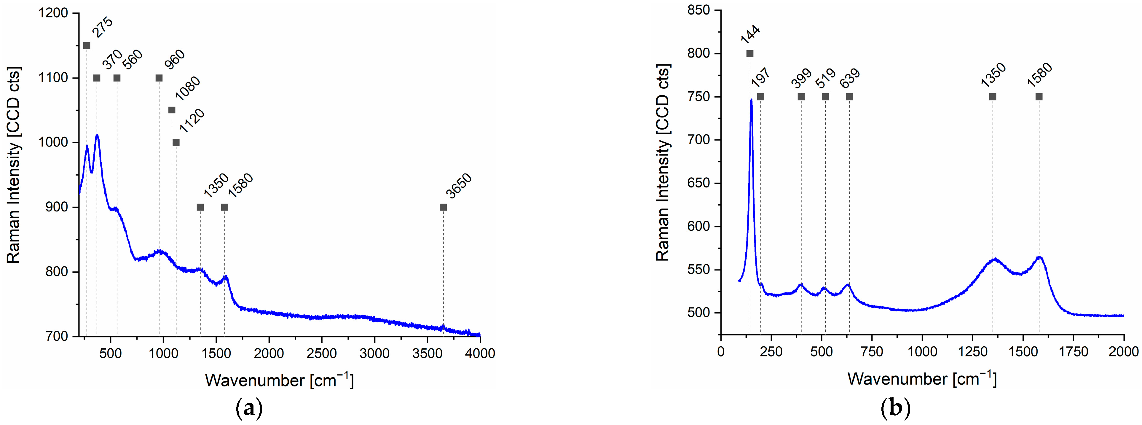
4.3. Raman Investigations

To examine the resulting coatings of the carbon fibers, Raman investigations were conducted. For the MgO quasi-continuous EPD, the results of the investigations are shown in Figure 6. While the peaks at 448, 1080, and 1120 cm−1 show the presence of the MgO nanoparticles, the peak at 3650 cm−1 corresponds to the O-H bond and indicates the formation of Mg(OH)2, while peaks at 275, 370, 580, and 960 cm−1 are not visible [71,72]. The peak at 1350 cm−1 indicates the presence of defect-related features in the carbon fiber structure, while the peak at 1580 cm−1 corresponds to the vibrational mode of sp2-bonded carbon atoms [73].
Additionally, Raman spectroscopy was performed on the PVD-fabricated films, confirming the presence of MgO nanoparticles in the Mg PVD (Figure 7a) samples and anatase-phase TiO2 (Figure 7b) in the TiO2 PVD samples. Characteristic peaks at 275, 370, 580, and 960 cm−1 indicate the formation of MgO on the carbon fiber surface, while a weak peak at 3650 cm−1 suggests the presence of Mg(OH)2, likely formed due to ambient moisture [71,72]. The carbon fiber itself is characterized by peaks at 1350 and 1589 cm−1, corresponding to defect-related and sp2-bonded carbon, respectively [73]. In the case of TiO2 deposition, Raman peaks observed at 144, 197, 399, 519, and 639 cm−1 confirm the formation of the anatase phase during the PVD process [74]. Again, the peaks at 1350 and 1589 cm−1 represent the underlying carbon fiber structure [73].

4.4. XRD Analysis

Further structural analysis of the EPD-modified carbon fibers was performed using X-ray diffraction (XRD), with the results presented in Figure 8. Prominent diffraction peaks were observed at 31.6°, 36.9°, and 41.27° and a small one was observed at 72.4°. These peaks suggest the presence of a mixed phase comprising magnesium oxide (MgO) and magnesium hydroxide (Mg(OH)2), corresponding approximately to JCPDS cards 01-077-2906 and 00-044-1482, respectively. The broad peak observed at 24.7° can be attributed to the disordered graphitic domains present in the carbon fiber.

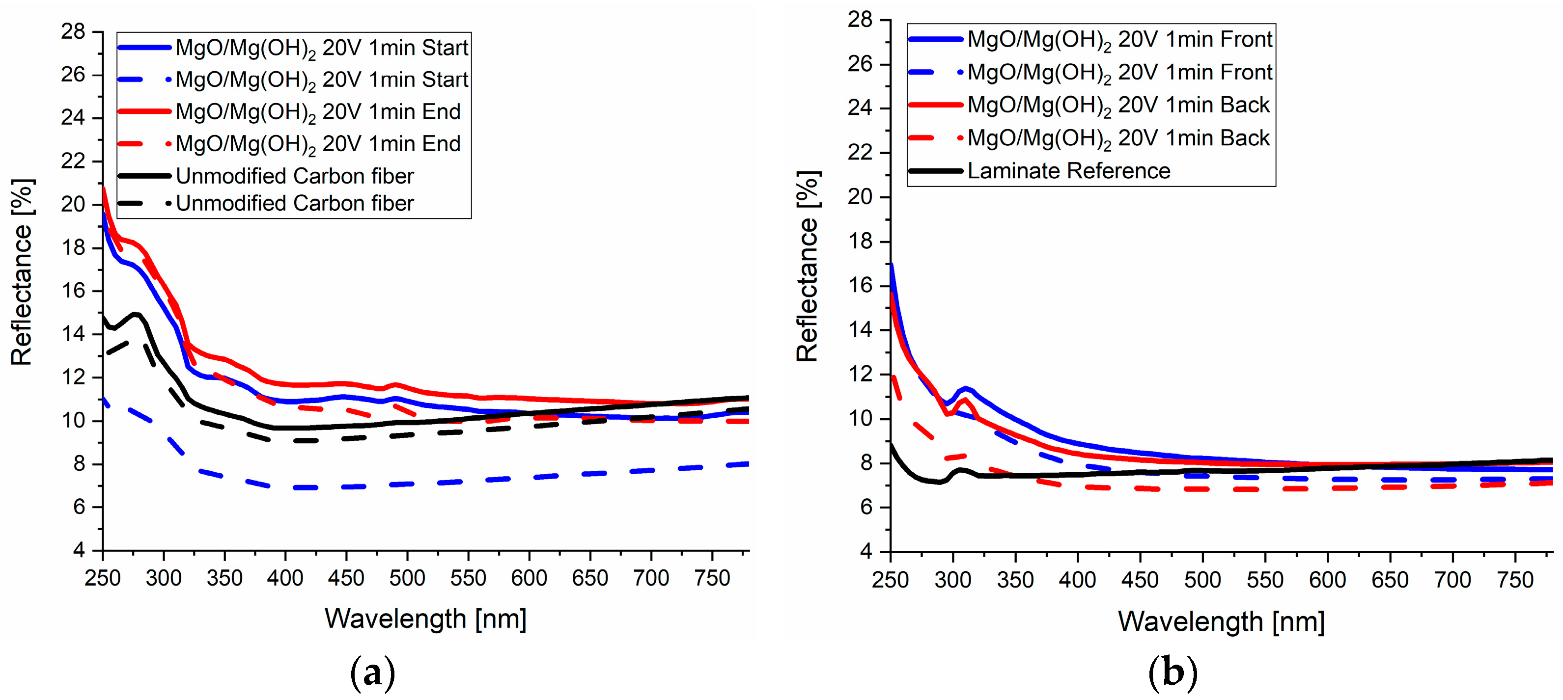
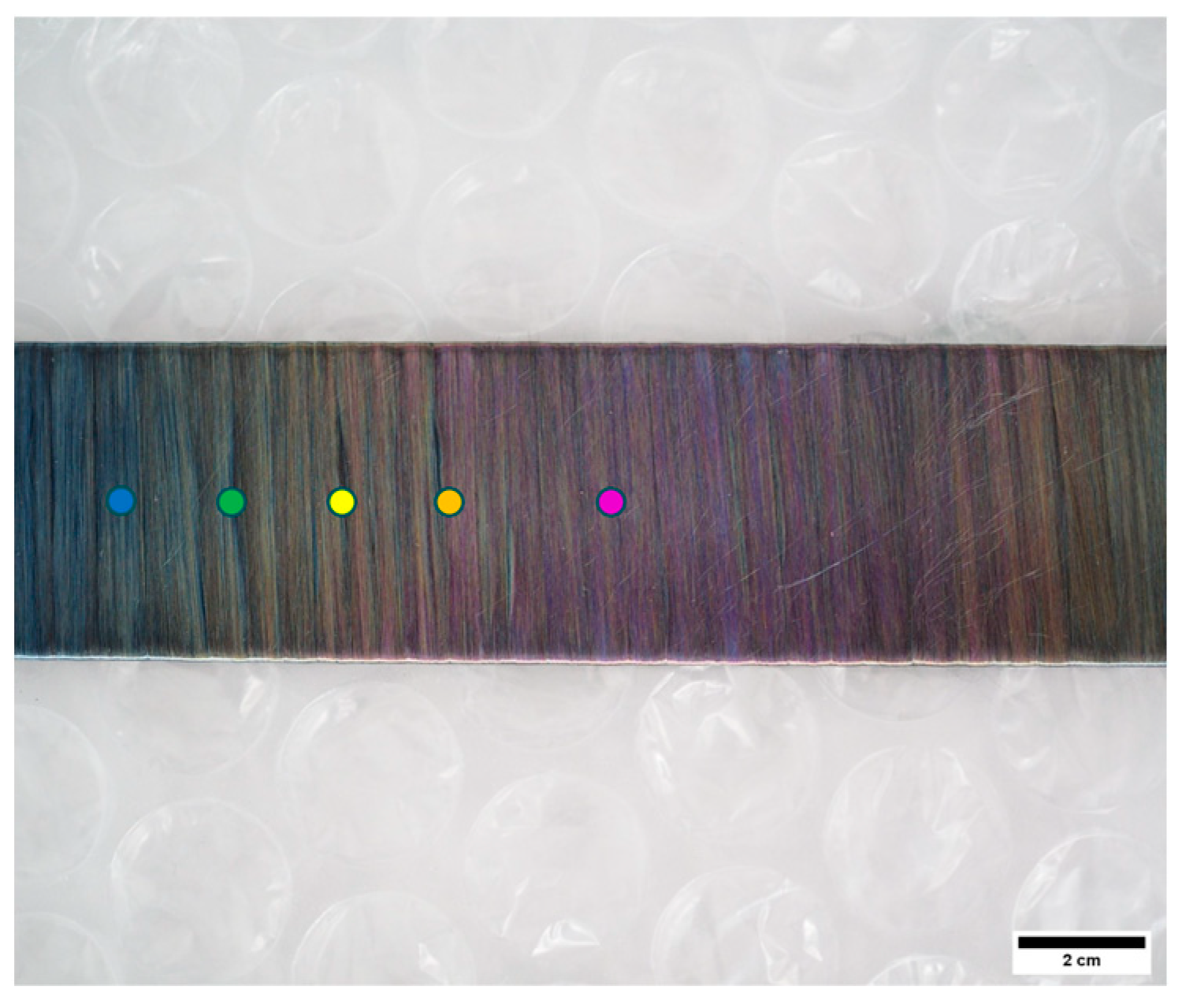
4.5. Deposition Analysis and Optical Investigations

In the following sections, selected results will be presented that focus on changes in optical reflectance due to fiber modifications. Initially, the impact of quasi-continuous EPD on modified carbon fibers and the resulting laminates, in comparison to untreated fibers and corresponding unmodified fibers, will be discussed. To evaluate the quality of the carbon fiber coatings with various nanoparticles and deposition parameters, fibers were sampled at the beginning and end of the deposition and winding processes and analyzed using SEM imaging. Additionally, carbon fibers coated via PVD were examined using SEM and UV/Vis measurements both before and after the lamination process, as described in the subsequent sections.

4.5.1. Quasi-Continuous EPD Using MgO Nanoparticles

MgO nanoparticles were used which have notable optical properties including high reflectivity in the visible and UV regions that can be tuned by particle size and shape [37,40]. They have a varying refractive index and strong scattering properties which affect their optical characteristics [44]. Figure 9 illustrates the SEM-assessed coverage quality at the beginning and end of the deposition process for MgO nanoparticles using 20 V and a 1 min deposition time. Figure 9a, taken at a higher magnification (FoV 12.7 µm), shows carbon fibers with a fine distribution of nanoparticles across their surfaces. Here, the nanoparticles are more clearly visible, showing a relatively uniform coverage, with the nanoparticles being small and dispersed along the fibers. In contrast, Figure 9b, taken at a lower magnification (FoV 63.5 µm), displays larger clusters and agglomerations compared to the first image. The coverage is denser, with a more significant accumulation of particles on the fiber surfaces. Overall, at the end of the deposition process, Figure 9b highlights a greater degree of nanoparticle clustering and denser coverage on the carbon fibers, whereas the beginning of the deposition, Figure 9a, shows a more even but less dense distribution of nanoparticles. The images show fine coverage on most carbon fiber surfaces; however, uncovered areas remain more extensive.
The UV/Vis measurements (Figure 10a) before lamination show a significant increase in reflectance in the UV range for almost all measured samples. The modified fibers show a drop in reflectance towards the visible range, and decrease below the value of the unmodified fibers in the area of around approximately 550 nm. It is interesting to note that there is a big effect of the fiber orientation of the samples which show a difference (up to 6% at 250 nm) over the whole measured range. The spectrum of the vertically aligned fiber sample at the start of the EPD process shows the most distinct variation, with consistently lower reflectance across the entire measurement range compared to the unmodified carbon fiber. After the lamination (Figure 10b), the reflectance is lower compared to the non-laminated counterparts in all the measured ranges and is comparable to the unmodified laminate in the visible area. There is still an up to 100% increase in the reflectance in the UV range but this is less pronounced compared to the values before lamination. Also, orientation differences lead to smaller changes in reflectance values compared to those prior to lamination. It is noteworthy that only minor changes in reflectance were observed between the beginning and end of the deposition process, indicating that the coating quality remained consistent throughout. After lamination, slight variations in reflectance were detected depending on whether the measurement was taken from the front or back side of the laminate. The front side corresponds to the surface in contact with the vacuum foil, while the back side was in contact with the steel plate. These minor differences may result from the use of a release agent applied to the steel plates to facilitate the removal of the laminate after curing.

4.5.2. PVD-Based Deposition of Mg Thin Films

A picture of the optical appearance of Mg-coated carbon fibers is shown in Figure 11. The quality of the PVD process was evaluated using a SEM. Figure 12a,b display the SEM images of carbon fibers coated with Mg films of 50 nm and 250 nm thicknesses. The images indicate that carbon fibers with a 50 nm Mg film have partial Mg coverage, with certain regions lacking deposition. In contrast, carbon fibers with a 250 nm Mg film exhibit consistent and complete coverage, featuring a rough surface texture. It is important to note that Mg is highly susceptible to oxidation. As a result, a thin layer of MgO naturally forms on the surface of Mg films. This presence of MgO is further confirmed by EDX measurements (Figure 12c). The results of the reflectance measurements are presented in Figure 13. Prior to the laminations, film thicknesses of up to 50 nm show no observable change in reflectance compared to the unmodified carbon fibers. However, films with thicknesses of 250 nm and 500 nm exhibit a significant increase in reflectance in both the visible and UV ranges. Notably, the reflectance is comparable between the 250 nm and 500 nm films, indicating no apparent difference between these thicknesses. After lamination, 10 nm, 50 nm, and 500 nm samples show in the whole measurement range higher reflectance than the unmodified laminate reference. Around 300 nm, a noticeable drop in reflectance occurs, followed by a sharp increase in the UV region. Reflectance increases with increasing film thickness, as thicker films result in more uniform coverage during the PVD process, reducing uncoated spots. An example for the repeatability of the measurements is presented in Figure 13c. Measurements on the same spot result in the exact same spectrum. Deviations in the area of measurement result in a change in the obtained spectra of up to 2% in total reflectance. This observation is valid for all measured samples in this manuscript. Nevertheless, they still indicate the valid trends.

4.5.3. PVD-Based Deposition of TiO2 Thin Films

Thin films of TiO2 produced by PVD can alter the transmittance and wavelength of light that passes through them. The optical properties of these films, particularly the wavelengths of light that are transmitted or reflected, are largely influenced by their thickness. This enables the precise manipulation of both the color and intensity of light, which is vital for applications such as optical coatings and anti-reflective surfaces.
Optical investigations show colorful carbon fibers whose distinctive colors vary according to their corresponding TiO2 film thickness (Figure 14). The measured points are depicted there whereas their reflectance results are shown in Figure 15. The 50 nm film reflects blue light, the 124 nm film reflects green, the 142 nm film reflects yellow, the 175 nm reflects orange, and the 185 nm films reflect purple light (Figure 15a). After lamination (Figure 15b) with the usage of peel ply and flowing aid, wavelengths below 450 nm exhibit higher reflectance values compared to the unmodified laminate, with all samples showing a local maximum at 300–350 nm and a strong increase at 250 nm. Nevertheless, the colors in the range of 450 nm–780 nm disappeared or became dull after lamination. Figure 15c presents the results after altering the lamination process using no peel ply and flow aid. The colors remain visible even after lamination, indicating that the manufacturing process significantly influences the optical properties.

5. Conclusions

This study has provided valuable insights into advancing the optical properties of CFRPs through innovative surface modification techniques involving MgO, Mg, and TiO2 nanoparticles’ deposition or creating thin films on the carbon fiber surface. The findings underscore the potential of these modifications to significantly enhance both the esthetic and functional characteristics of CFRPs, while also identifying key areas for optimization.
EPD has been demonstrated as an effective method for depositing MgO nanoparticles onto carbon fibers for incorporation into laminates, resulting in laminates with elevated UV reflectivity and moderate increases in the visible range. However, the method presents challenges, particularly the clustering and uneven distribution of nanoparticles, which must be addressed to achieve consistent and reliable optical modifications across the material. Furthermore, MgO nanoparticles undergo transformation into Mg(OH)2 when dispersed in an aqueous suspension. This conversion results in an increased absorption capacity and reduced reflectance. In contrast, utilizing a non-aqueous suspension would inhibit this transformation, thereby enhancing the reflectance—particularly in the ultraviolet (UV) range. PVD has shown considerable promise in achieving tailored optical properties. Mg films applied through PVD exhibit a marked increase in reflectance within both UV and visible light spectra as film thickness increases. Meanwhile, TiO2 coatings have proven to be highly versatile, enabling the precise manipulation of optical characteristics through controlled film thickness. This results in distinct interference effects and enhanced reflectance in targeted wavelength ranges, making them suitable for both functional and decorative applications.
Post-lamination effects reveal that while the lamination process reduces the optical enhancements achieved by both EPD and PVD modifications—primarily due to resin impregnation—substantial improvements in UV reflectivity are retained, underscoring the robustness of these modifications. A drawback is the usage of peel ply and flowing aid during the lamination as the resulting composites show a high surface roughness, which may affect the UV/Vis measurements.
Furthermore, the UV/Vis results strongly depend on the calibration process. Despite thorough calibration, variations in reflectance were repeatability observed especially in the UV range, posing challenges for the precise quantification of absolute reflectance values. Measured reflectance can vary up to ±2% in absolute values (e.g., for 15%, it can be between 13 and 17%) depending on the area measured on the specific sample. Nevertheless, all data clearly reveal consistent trends of either increased or decreased reflectance compared to the unmodified carbon fiber or laminate sample. Differences in fiber orientation may lead to optical variations driven by the geometry and optical anisotropy of the carbon fibers, potentially amplified by the presence of nanoparticles or thin films, as well as their internal structure. In practical use, the reflectivity of laminates may be influenced over time by aging under diverse operational environments.
This work highlights the potential of Mg, MgO, and TiO2 as powerful agents for tailoring the optical properties of CFRPs. At the same time, it emphasizes the importance of further research to address current limitations such as particle dispersion uniformity and the effects of lamination on optical performance. These advancements could pave the way for broader applications of modified CFRPs in industries such as aerospace, automotive, and architecture, where both functionality and esthetics are of critical importance.

Author Contributions

Conceptualization, L.H., M.F., A.J.B., and M.B.; methodology, L.H., M.F., V.T., B.R., and A.P.; validation, L.H., M.F., and A.J.B.; formal analysis, L.H.; investigation, L.H.; resources, M.F. and G.P.; writing—original draft preparation, L.H.; writing—review and editing, L.H., M.F., M.B., and A.J.B.; visualization, L.H.; supervision, M.F. and A.J.B.; project administration, M.F.; funding acquisition, M.F. and G.P. All authors have read and agreed to the published version of the manuscript.

Funding

This research received no external funding.

Data Availability Statement

The data supporting the findings of this study are not publicly available but can be obtained from the corresponding author upon reasonable request.

Acknowledgments

We gratefully acknowledge Montanuniversität Leoben for funding this project, Hexcel for supplying unsized AS4 carbon fibers, and the Swiss Federal Laboratories for Materials Science and Technology for providing access to the quasi-continuous EPD setup. ChatGPT 4o was used to improve text quality and readability.

Conflicts of Interest

The authors state no conflicts of interest.

References

  1. Liu, K.; Macosko, C.W. Can nanoparticle toughen fiber-reinforced thermosetting polymers? J. Mater. Sci. 2019, 54, 4471–4483. [Google Scholar] [CrossRef]
  2. Rashid, A.B.; Haque, M.; Islam, S.M.M.; Uddin Labib, K.M.R. Nanotechnology-enhanced fiber-reinforced polymer composites: Recent advancements on processing techniques and applications. Heliyon 2024, 10, e24692. [Google Scholar] [CrossRef]
  3. Böger, L.; Sumfleth, J.; Hedemann, H.; Schulte, K. Improvement of fatigue life by incorporation of nanoparticles in glass fibre reinforced epoxy. Compos. Part A Appl. Sci. Manuf. 2010, 41, 1419–1424. [Google Scholar] [CrossRef]
  4. Carolan, D.; Ivankovic, A.; Kinloch, A.J.; Sprenger, S.; Taylor, A.C. Toughened carbon fibre-reinforced polymer composites with nanoparticle-modified epoxy matrices. J. Mater. Sci. 2017, 52, 1767–1788. [Google Scholar] [CrossRef]
  5. Rankin, S.M.; Moody, M.K.; Naskar, A.K.; Bowland, C.C. Enhancing functionalities in carbon fiber composites by titanium dioxide nanoparticles. Compos. Sci. Technol. 2021, 201, 108491. [Google Scholar] [CrossRef]
  6. Tang, Y.; Ye, L.; Zhang, Z.; Friedrich, K. Interlaminar fracture toughness and CAI strength of fibre-reinforced composites with nanoparticles—A review. Compos. Sci. Technol. 2013, 86, 26–37. [Google Scholar] [CrossRef]
  7. Gangineni, P.K.; Gupta K., B.N.V.S.G.; Patnaik, S.; Prusty, R.K.; Ray, B.C. Recent advancements in interface engineering of carbon fiber reinforced polymer composites and their durability studies at different service temperatures. Polym. Compos. 2022, 43, 4126–4164. [Google Scholar] [CrossRef]
  8. Hashim, U.R.; Jumahat, A.; Jawaid, M.; Dungani, R.; Alamery, S. Effects of Accelerated Weathering on Degradation Behavior of Basalt Fiber Reinforced Polymer Nanocomposites. Polymers 2020, 12, 2621. [Google Scholar] [CrossRef]
  9. Yudaev, P.; Chuev, V.; Klyukin, B.; Kuskov, A.; Mezhuev, Y.; Chistyakov, E. Polymeric Dental Nanomaterials: Antimicrobial Action. Polymers 2022, 14, 864. [Google Scholar] [CrossRef]
  10. Spinelli, G.; Lamberti, P.; Tucci, V.; Guadagno, L.; Vertuccio, L. Damage Monitoring of Structural Resins Loaded with Carbon Fillers: Experimental and Theoretical Study. Nanomaterials 2020, 10, 434. [Google Scholar] [CrossRef]
  11. Michael, M. On “Aesthetic Publics”. Sci. Technol. Hum. Values 2018, 43, 1098–1121. [Google Scholar] [CrossRef]
  12. Perovich, D.K. Light reflection and transmission by a temperate snow cover. J. Glaciol. 2007, 53, 201–210. [Google Scholar] [CrossRef]
  13. Ulaeto, S.B.; Ravi, R.P.; Udoh, I.I.; Mathew, G.M.; Rajan, T.P.D. Polymer-Based Coating for Steel Protection, Highlighting Metal–Organic Framework as Functional Actives: A Review. Corros. Mater. Degrad. 2023, 4, 284–316. [Google Scholar] [CrossRef]
  14. Jones, F.N.; Nichols, M.E.; Pappas, S.P. Organic Coatings: Science and Technology, 4th ed.; John Wiley & Sons: Hoboken, NJ, USA, 2017; ISBN 9781119026891. [Google Scholar]
  15. Khanna, A.S. High-Performance Organic Coatings; Woodhead Publishing Limited: Cambridge, UK, 2008; ISBN 9781845694739. [Google Scholar]
  16. Meyer, R.W. Handbook of Polyester Molding Compounds and Molding Technology; Springer: Boston, MA, USA, 1987; ISBN 9781461319610. [Google Scholar]
  17. Pomázi, Á.; Toldy, A. Multifunctional Gelcoats for Fiber Reinforced Composites. Coatings 2019, 9, 173. [Google Scholar] [CrossRef]
  18. Lackner, J.; Waldhauser, W.; Major, L.; Kot, M. Tribology and Micromechanics of Chromium Nitride Based Multilayer Coatings on Soft and Hard Substrates. Coatings 2014, 4, 121–138. [Google Scholar] [CrossRef]
  19. Major, L.; Janusz, M.; Kot, M.; Lackner, J.M.; Major, B. Development and complex characterization of bio-tribological Cr/CrN + a-C:H (doped Cr) nano-multilayer protective coatings for carbon–fiber-composite materials. RSC Adv. 2015, 5, 9405–9415. [Google Scholar] [CrossRef]
  20. Kozlova, A.A.; Kondrashov, E.K.; Deev, I.S. Protective properties of paint and lacquer coatings based on a fluorine-containing film-forming material. Prot. Met. Phys. Chem. Surf. 2016, 52, 1181–1186. [Google Scholar] [CrossRef]
  21. Henke, M.; Lis, B.; Krystofiak, T. Mechanical and Chemical Resistance of UV Coating Systems Prepared under Industrial Conditions Using LED Radiation. Polymers 2023, 15, 4550. [Google Scholar] [CrossRef]
  22. Chandrababu, V.; Parameswaranpillai, J.; Gopi, J.A.; Pathak, C.; Midhun Dominic, C.D.; Feng, N.L.; Krishnasamy, S.; Muthukumar, C.; Hameed, N.; Ganguly, S. Progress in food packaging applications of biopolymer-nanometal composites—A comprehensive review. Biomater. Adv. 2024, 162, 213921. [Google Scholar] [CrossRef]
  23. Wang, H.; Xie, H.; Hu, Z.; Wu, D.; Chen, P. The influence of UV radiation and moisture on the mechanical properties and micro-structure of single Kevlar fibre using optical methods. Polym. Degrad. Stab. 2012, 97, 1755–1761. [Google Scholar] [CrossRef]
  24. Singh, B.; Sharma, N. Mechanistic implications of plastic degradation. Polym. Degrad. Stab. 2008, 93, 561–584. [Google Scholar] [CrossRef]
  25. Sampers, J.; Hutten, E.; Gijsman, P. Accelerated weathering of unsaturated polyester resins. Aspects of appearance change. Polym. Test. 2015, 44, 208–223. [Google Scholar] [CrossRef]
  26. Rumchev, K.; Brown, H.; Spickett, J. Volatile organic compounds: Do they present a risk to our health? Rev. Environ. Health 2007, 22, 39–55. [Google Scholar] [CrossRef]
  27. Pandey, P.; Yadav, R. A Review on Volatile Organic Compounds (VOCs) as Environmental Pollutants: Fate and Distribution. IJPE 2018, 4, 14–26. [Google Scholar] [CrossRef]
  28. Di Tomasso, C.; József Gombos, Z.; Summerscales, J. Styrene emissions during gel-coating of composites. J. Clean. Prod. 2014, 83, 317–328. [Google Scholar] [CrossRef]
  29. Chaturvedi, S.; Kumar, A.; Singh, V.; Chakraborty, B.; Kumar, R.; Min, L. Recent Advancement in Organic Aerosol Understanding: A Review of Their Sources, Formation, and Health Impacts. Water Air Soil Pollut 2023, 234, 750. [Google Scholar] [CrossRef]
  30. Wu, Y.; Wu, X.; Yang, F.; Ye, J. Preparation and Characterization of Waterborne UV Lacquer Product Modified by Zinc Oxide with Flower Shape. Polymers 2020, 12, 668. [Google Scholar] [CrossRef]
  31. Pieters, K.; Mekonnen, T.H. Progress in waterborne polymer dispersions for coating applications: Commercialized systems and new trends. RSC Sustain. 2024, 2, 3704–3729. [Google Scholar] [CrossRef]
  32. Li, S.; Meng Lin, M.; Toprak, M.S.; Kim, D.K.; Muhammed, M. Nanocomposites of polymer and inorganic nanoparticles for optical and magnetic applications. Nano Rev. 2010, 1, 1–19. [Google Scholar] [CrossRef] [PubMed]
  33. Haiden, L.; Brunner, A.J.; Pansare, A.V.; Feuchter, M.; Pinter, G. Tailoring the optical and UV reflectivity of CFRP-epoxy composites: Approaches and selected results. Sci. Eng. Compos. Mater. 2023, 30, 20220175. [Google Scholar] [CrossRef]
  34. Haiden, L.; Feuchter, M.; Brunner, A.J.; Pansare, A.; Barbezat, M.; Ravindran, B.; Terziyska, V.; Pinter, G. Altering the optical appearance of carbon reinforced polymers on an intrinsic level using Ag and SiO2. Proc. Inst. Mech. Eng. Part L 2025, 239, 733–745. [Google Scholar] [CrossRef]
  35. Dong, M.; Zhang, H.; Tzounis, L.; Santagiuliana, G.; Bilotti, E.; Papageorgiou, D.G. Multifunctional epoxy nanocomposites reinforced by two-dimensional materials: A review. Carbon 2021, 185, 57–81. [Google Scholar] [CrossRef]
  36. Yang, J.; Wang, J.; Strømme, M.; Welch, K. Enhanced UV protection and water adsorption properties of transparent poly(methyl methacrylate) films through incorporation of amorphous magnesium carbonate nanoparticles. J. Polym. Res. 2021, 28, 281. [Google Scholar] [CrossRef]
  37. Stankic, S.; Müller, M.; Diwald, O.; Sterrer, M.; Knözinger, E.; Bernardi, J. Size-dependent optical properties of MgO nanocubes. Angew. Chem. Int. Ed. Engl. 2005, 44, 4917–4920. [Google Scholar] [CrossRef] [PubMed]
  38. Kumar, A.; Kumar, J. On the synthesis and optical absorption studies of nano-size magnesium oxide powder. J. Phys. Chem. Solids 2008, 69, 2764–2772. [Google Scholar] [CrossRef]
  39. Choudhury, B.; Choudhury, A. Microstructural, optical and magnetic properties study of nanocrystalline MgO. Mater. Res. Express 2014, 1, 25026. [Google Scholar] [CrossRef]
  40. Zwijnenburg, M.A. The effect of particle size on the optical and electronic properties of magnesium oxide nanoparticles. Phys. Chem. Chem. Phys. 2021, 23, 21579–21590. [Google Scholar] [CrossRef]
  41. Reiling, G.H.; Hensley, E.B. Fundamental Optical Absorption in Magnesium Oxide. Phys. Rev. 1958, 112, 1106–1111. [Google Scholar] [CrossRef]
  42. Roessler, D.M.; Walker, W.C. Electronic Spectrum and Ultraviolet Optical Properties of Crystalline MgO. Phys. Rev. 1967, 159, 733–738. [Google Scholar] [CrossRef]
  43. Chayed, N.F.; Badar, N.; Rusdi, R.; Kamarudin, N.; Kamarulzaman, N. Optical Band Gap Energies of Magnesium Oxide (MgO) Thin Film and Spherical Nanostructures. AIP Conf. Proc. 2011, 1400, 328–332. [Google Scholar] [CrossRef]
  44. Townsend, J.R. Solid-State Absorption Spectra of Mg and MgO. Phys. Rev. 1953, 92, 556–560. [Google Scholar] [CrossRef]
  45. Cohen, M.L.; Lin, P.J.; Roessler, D.M.; Walker, W.C. Ultraviolet Optical Properties and Electronic Band Structure of Magnesium Oxide. Phys. Rev. 1967, 155, 992–996. [Google Scholar] [CrossRef]
  46. de Silva, R.T.; Mantilaka, M.M.M.G.P.G.; Ratnayake, S.P.; Amaratunga, G.A.J.; de Silva, K.M.N. Nano-MgO reinforced chitosan nanocomposites for high performance packaging applications with improved mechanical, thermal and barrier properties. Carbohydr. Polym. 2017, 157, 739–747. [Google Scholar] [CrossRef]
  47. Gatou, M.-A.; Skylla, E.; Dourou, P.; Pippa, N.; Gazouli, M.; Lagopati, N.; Pavlatou, E.A. Magnesium Oxide (MgO) Nanoparticles: Synthetic Strategies and Biomedical Applications. Crystals 2024, 14, 215. [Google Scholar] [CrossRef]
  48. Han, S.; Zhang, J.; Qi, Y. A novel comprehensive composite material for auxiliary solar photovoltaic double-sided power generation: Combining reflective cooling, flame retardant, and smoke suppressant properties. Mater. Today Commun. 2025, 44, 112087. [Google Scholar] [CrossRef]
  49. Sun, H.; Qi, Y.; Zhang, J. Effect of magnesium hydroxide as a multifunctional additive on high solar reflectance, thermal emissivity, and flame retardancy properties of PP/SEBS/oil composites. Polym. Compos. 2020, 41, 4010–4019. [Google Scholar] [CrossRef]
  50. Hagemann, H.-J.; Gudat, W.; Kunz, C. Optical constants from the far infrared to the x-ray region: Mg, Al, Cu, Ag, Au, Bi, C, and Al2O3. J. Opt. Soc. Am. 1975, 65, 742–744. [Google Scholar] [CrossRef]
  51. Kroger, H.; Tomboulian, D.H. Far Ultraviolet Absorption Spectrum of Magnesium. Phys. Rev. 1963, 130, 152–154. [Google Scholar] [CrossRef]
  52. Sabine, G.B. Reflectivities of Evaporated Metal Films in the Near and Far Ultraviolet. Phys. Rev. 1939, 55, 1064–1069. [Google Scholar] [CrossRef]
  53. Vidal-Dasilva, M.; Aquila, A.L.; Gullikson, E.M.; Salmassi, F.; Larruquert, J.I. Optical constants of magnetron-sputtered magnesium films in the 25–1300 eV energy range. J. Appl. Phys. 2010, 108, 063517. [Google Scholar] [CrossRef]
  54. O’Bryan, H.M. The Optical Constants of Several Metals in Vacuum*. J. Opt. Soc. Am. 1936, 26, 122–127. [Google Scholar] [CrossRef]
  55. Nam, K.H.; Han, J.G. Microstructure and optical properties of MgO films synthesized by closed-field unbalanced magnetron sputtering with additional electron emission. Surf. Coat. Technol. 2003, 171, 51–58. [Google Scholar] [CrossRef]
  56. Ahmad, A.F.; Ab Aziz, S.; Abbas, Z.; Obaiys, S.J.; Khamis, A.M.; Hussain, I.R.; Zaid, M.H.M. Preparation of a Chemically Reduced Graphene Oxide Reinforced Epoxy Resin Polymer as a Composite for Electromagnetic Interference Shielding and Microwave-Absorbing Applications. Polymers 2018, 10, 1180. [Google Scholar] [CrossRef]
  57. Hanemann, T.; Szabó, D.V. Polymer-Nanoparticle Composites: From Synthesis to Modern Applications. Materials 2010, 3, 3468–3517. [Google Scholar] [CrossRef]
  58. Schönberger, W.; Bartzsch, H.; Schippel, S.; Bachmann, T. Deposition of rutile TiO2 films by pulsed and high power pulsed magnetron sputtering. Surf. Coat. Technol. 2016, 293, 16–20. [Google Scholar] [CrossRef]
  59. Radhakrishnan, T. The optical properties of titanium dioxide. Proc. Indian Acad. Sci. (Math. Sci.) 1952, 35, 117–125. [Google Scholar] [CrossRef]
  60. Soussi, A.; Ait Hssi, A.; Boujnah, M.; Boulkadat, L.; Abouabassi, K.; Asbayou, A.; Elfanaoui, A.; Markazi, R.; Ihlal, A.; Bouabid, K. Electronic and Optical Properties of TiO2 Thin Films: Combined Experimental and Theoretical Study. J. Electron. Mater. 2021, 50, 4497–4510. [Google Scholar] [CrossRef]
  61. Zywitzki, O.; Modes, T.; Sahm, H.; Frach, P.; Goedicke, K.; Glöß, D. Structure and properties of crystalline titanium oxide layers deposited by reactive pulse magnetron sputtering. Surf. Coat. Technol. 2004, 180–181, 538–543. [Google Scholar] [CrossRef]
  62. Skowronski, L.; Chodun, R.; Zdunek, K. TiO2—based decorative interference coatings produced at industrial conditions. Thin Solid Film. 2020, 711, 138294. [Google Scholar] [CrossRef]
  63. Skowroński, Ł.; Trzcinski, M.; Antończak, A.J.; Domanowski, P.; Kustra, M.; Wachowiak, W.; Naparty, M.K.; Hiller, T.; Bukaluk, A.; Wronkowska, A.A. Characterisation of coloured TiO /Ti/glass systems. Appl. Surf. Sci. 2014, 322, 209–214. [Google Scholar] [CrossRef]
  64. Lin, Y.-C. Novel Optical Thin Film Color Filter: Simulation and Experiment. Chin. J. Physic 2012, 50, 643–651. [Google Scholar]
  65. Soled, S.; Wachter, W.; Wo, H. Use of zeta potential measurements in catalyst preparation. In Studies in Surface Science and Catalysis: Scientific Bases for the Preparation of Heterogeneous Catalysts; Gaigneaux, E.M., Devillers, M., Hermans, S., Jacobs, P.A., Martens, J.A., Ruiz, P., Eds.; Elsevier: Amsterdam, The Netherlands, 2010; pp. 101–107. ISBN 0167-2991. [Google Scholar]
  66. Lin, J.X.; Wang, L. Adsorption of dyes using magnesium hydroxide-modified diatomite. Desalination Water Treat. 2009, 8, 263–271. [Google Scholar] [CrossRef]
  67. Ferrari, B.; Moreno, R.; Sarkar, P.; Nicholson, P.S. Electrophoretic deposition of MgO from organic suspensions. J. Eur. Ceram. Soc. 2000, 20, 99–106. [Google Scholar] [CrossRef]
  68. Robinson, M.; Pask, J.A.; Fuerstenau, D.W. Surface Charge of Alumina and Magnesia in Aqueous Media. J. Am. Ceram. Soc. 1964, 47, 516–520. [Google Scholar] [CrossRef]
  69. Swann, S. Film thickness distribution in magnetron sputtering. Vacuum 1988, 38, 791–794. [Google Scholar] [CrossRef]
  70. Ozimek, M.; Wilczyński, W.; Szubzda, B. Magnetic thin film deposition with pulsed magnetron sputtering: Deposition rate and film thickness distribution. IOP Conf. Ser. Mater. Sci. Eng. 2016, 113, 12009. [Google Scholar] [CrossRef]
  71. Dekermenjian, M.; Ruediger, A.P.; Merlen, A. Raman spectroscopy investigation of magnesium oxide nanoparticles. RSC Adv. 2023, 13, 26683–26689. [Google Scholar] [CrossRef]
  72. Morozov, I.; Sathasivam, S.; Belousova, O.V.; Parkin, I.P.; Kuznetcov, M.V. Effect of synthesis conditions on room-temperature ferromagnetic properties of Mg-O nanoparticles. J. Alloys Compd. 2018, 765, 343–354. [Google Scholar] [CrossRef]
  73. Brubaker, Z.E.; Langford, J.J.; Kapsimalis, R.J.; Niedziela, J.L. Quantitative analysis of Raman spectral parameters for carbon fibers: Practical considerations and connection to mechanical properties. J. Mater. Sci. 2021, 56, 15087–15121. [Google Scholar] [CrossRef]
  74. Ohsaka, T.; Izumi, F.; Fujiki, Y. Raman spectrum of anatase, TiO2. J. Raman Spectrosc. 1978, 7, 321–324. [Google Scholar] [CrossRef]
Figure 1. Schematic of the quasi-continuous electrophoretic deposition (EPD) apparatus.
Jcs 09 00187 g001
Figure 2. A photograph was taken immediately after TiO2 deposition, showing carbon fibers mounted in the physical vapor deposition (PVD) coating device, with silicon wafers placed above and below for film thickness measurements.
Jcs 09 00187 g002
Figure 3. (a) Schematic of the lamination process for the quasi-continuous EPD-modified sample and respective photographs of (b) before and (c) during the manufacturing of the composite. Images of PVD (Mg/MgO)-modified fibers (d) before and (e) after lamination.
Jcs 09 00187 g003
Figure 4. Measurement of film thickness in the yellow region of the deposited TiO2 (a) conducted with AFM and assessed using Gwyddion software 2.58. The orange line represents the profile line shown in (b).
Jcs 09 00187 g004
Figure 5. The evaluation using the laser confocal microscope involved selecting distinct points in the uncoated and coated areas, respectively. The height difference between these two points was then precisely measured to determine the film thickness. Measurement was conducted in the optical blue area of the deposited TiO2.
Jcs 09 00187 g005
Figure 6. Raman measurement on the quasi-continuous EPD-modified carbon fibers using MgO nanoparticles.
Jcs 09 00187 g006
Figure 7. Raman spectra of carbon fibers modified by PVD of (a) Mg and (b) TiO2 thin films.
Jcs 09 00187 g007
Figure 8. X-ray diffraction (XRD) characterization of MgO quasi-continuously deposited onto carbon fibers via electrophoretic deposition (EPD) from an aqueous suspension. The blue solid lines represent reference diffraction peaks of MgO, while the red dashed lines correspond to those of Mg(OH)2, as reported in the literature.
Jcs 09 00187 g008
Figure 9. MgO-modified carbon fibers using 20 V and 1 min during EPD (a) at the start and (b) at the end of the deposition process.
Jcs 09 00187 g009
Figure 10. Reflectance measurements of quasi-continuous EPD MgO nanoparticle-modified carbon fibers (a) prior to and (b) after the lamination process. The solid lines indicate horizontally oriented fibers, while the dashed lines represent vertically oriented fibers.
Jcs 09 00187 g010
Figure 11. An optical comparison of the reflectance of Mg/MgO-coated carbon fibers is presented. The thicknesses of the Mg films (from left to right) are 50 nm, 250 nm, and 500 nm.
Jcs 09 00187 g011
Figure 12. Mg/MgO-modified carbon fiber with a (a) 50 nm film and a (b) 250 nm film created during the PVD process. EDX measurements on the carbon fiber surface show the presence of oxygen and Mg and indicate the formation of MgO on the deposited thin film (c).
Jcs 09 00187 g012
Figure 13. Reflectance measurements of PVD Mg/MgO thin film-modified carbon fibers (a) before and (b) after the lamination process. The solid lines indicate horizontally oriented fibers, while the dashed lines represent vertically oriented fibers. The repeatability of the measurements is shown in (c). The spotted line in (c) represents a second measurement at the same spot.
Jcs 09 00187 g013
Figure 14. TiO2-modified carbon fibers showing distinctive colors before lamination process.
Jcs 09 00187 g014
Figure 15. Reflectance measurements of PVD TiO2 nanoparticle-modified carbon fibers (a) before and (b) after the lamination process with peel ply and flow aid, and (c) after lamination without peel ply and flow aid.
Jcs 09 00187 g015
Disclaimer/Publisher’s Note: The statements, opinions and data contained in all publications are solely those of the individual author(s) and contributor(s) and not of MDPI and/or the editor(s). MDPI and/or the editor(s) disclaim responsibility for any injury to people or property resulting from any ideas, methods, instructions or products referred to in the content.

