Article

Anisotropy and Strain Rate Sensitivity of Additively Manufactured Polymer Composites in Tension and Compression: Effects of Type and Orientation of Fibres

by
Md Niamul Islam
,
Konstantinos P. Baxevanakis
* and
Vadim V. Silberschmidt
Wolfson School of Mechanical, Electrical and Manufacturing Engineering, Loughborough University, Loughborough LE11 3TU, UK
*
Author to whom correspondence should be addressed.
J. Compos. Sci. 2025, 9(4), 186; https://doi.org/10.3390/jcs9040186
Submission received: 26 March 2025 / Revised: 3 April 2025 / Accepted: 9 April 2025 / Published: 11 April 2025
(This article belongs to the Special Issue Polymer Composites and Fibers, 3rd Edition)

Abstract

:
Comprehensive analysis of the anisotropic nature of additively manufactured (AM) parts caused by their fabrication method requires attention, as current quasi-static experiments on AM specimens are used to determine strength and stiffness. This study investigates the anisotropic mechanical behaviour of AM polymer composites reinforced with short and continuous carbon fibres, examining various filament orientations, loading directions and strain rates. Utilising the fused deposition modelling (FDM) technique, nylon and carbon fibres were fabricated into composites with controlled orientations. Mechanical tests were conducted in different directions to assess the tensile and compressive properties of these composites, with results showing enhanced tensile strength and stiffness in continuous-fibre (CF) composites compared to short-fibre (SF) ones, particularly in longitudinal orientations. The compressive behaviour revealed complex effects of type and orientation of reinforcing fibres, with CF composites demonstrating superior stiffness but lower strength than SF composites in specific orientations. Strain rate sensitivity analysis for the least anisotropic (quasi-isotropic) cases indicated that tensile strength decreased slightly with the increased strain rate while compressive strength increased. These findings underline the critical effect of fibre orientation and type on mechanical properties and suggest potential applications of AM composites in scenarios demanding tailored anisotropic behaviours, including structural optimisation and numerical modelling for various loading conditions.

1. Introduction

The ability of additive manufacturing (AM), or 3D printing, to produce complex shapes much easier than traditional methods to improve performance for various applications is currently the major focus of research [1,2,3,4,5]. Several studies summarised different AM techniques based on the type (metals, polymers and ceramics) and phase (powder, filament and liquid) of the used raw material [6,7,8,9]. They also include the performance analysis of printed structures, discussions of the drawbacks associated with the process (porosity, anisotropy and mass production) and applications across multiple industries (medical, aerospace, automotive, civil engineering, etc.).
Fused deposition modelling (FDM) is a popular method for thermoplastic polymers and composites (with the addition of reinforcing short or continuous fibres to produce stiffer and stronger structures), also known as material-extrusion additive manufacturing (MEAM) [10,11]. Manufacturing parameters play a significant role in the variation in MEAM structural properties demonstrated with thermal [12,13,14,15] and quasi-static mechanical tests [16,17,18,19,20,21,22,23], with the tensile test remaining a common mechanical experiment across these studies. Unidirectional composites, i.e., with filaments/fibres oriented in the loading direction, have demonstrated optimum performance. These continuous-fibre (CF) composites had significantly higher strength and stiffness with predictable properties compared to short-fibre (SF) composites with similar fibre contents [24,25,26]. Still, SF composites are advantageous over CF composites in terms of cost and time of manufacture, as the former are obtained by extruding a mixture of raw polymer and reinforcement material through a single nozzle [27,28,29,30,31]. In contrast, CF composites usually require dual extrusion of polymer and reinforcement separately, involving more complex machines [28,29,31,32,33].
Most studies rarely contribute to understanding the anisotropic nature of AM structures, as different filament/fibre orientations need to be investigated in addition to the impact of different loading directions and regimes, such as tension–compression behaviour and strain rate. Research on the tensile effect on MEAM composites loaded in the fibre direction remains common, with a handful of studies investigating the effects of strain rate and compression on these materials. However, the studies investigating strain rate effects did not provide a significant explanation of the outcomes, and the compressive response of these composites is affected by buckling, providing inconclusive answers, as it leads to premature failure and inadequate characterisation of structural properties and behaviour [34,35,36,37,38,39,40].
This paper aims to fill these gaps in understanding of the anisotropic behaviour of AM composites through a comprehensive analysis of these factors. Both short- and continuous-fibre reinforcements for different filament orientations are studied, considering the effects of different loading directions (including both tensile and compressive behaviours). Finally, the impact of significantly increased strain rates is investigated, with possible explanations behind the outcomes not discussed in previous studies. The results reveal the full potential of these composites for real-world applications which involve complex loading conditions. The obtained results could also be implemented in the numerical analysis of quasi-static and dynamic experiments to account for the anisotropic effect, develop a suitable damage model, reduce destructive testing and explore strategies for structural optimisation.

2. Methodology

2.1. Materials and Manufacturing Process

Nylon and carbon fibre were selected as raw materials for the MEAM matrix and reinforcement material, respectively, as the combination of these materials demonstrates high strength and stiffness compared to other AM materials [41,42]. The general MEAM structures investigated were pure nylon, nylon–matrix composites reinforced with short carbon fibres (denoted as NSCF) and continuous ones (NCCF). For NSCF samples, the raw filaments (PA6-CF) with 20 wt% fibre were obtained from Polymaker (Shanghai, China), and laminated structures were printed using the UltiMaker 2+ printer (Utrecht, The Netherlands), employing the UltiMaker Cura 5.0 software. The optical microscopy of the NSCF raw filament also confirmed the 20% fibre content (Figure 1a). On the other hand, the pure nylon (PA6) and continuous-carbon fibre filament (CCF) were acquired from Markforged (Waltham, MA, USA). The pure nylon (N) samples and the sandwich NCCF samples with 20% fibre content (80% pure nylon layers and 20% CCF layers) were fabricated with the Mark 2 printer (Waltham, MA, USA) using the Markforged Eiger 1.6 software. Optical microscopy of the raw CCF showed 50% fibre content Figure 1b), meaning that the overall fibre content in the NCCF composite structures was 10%.
Solid structures (100% infill) were produced for all the cases, and the printing parameters of these structures are listed in Table 1. Additionally, three different filament orientations were studied for each primary composite structure: longitudinal, transverse and quasi-isotropic, with extruded filaments oriented parallel, perpendicular and at all four used angles to the loading direction, respectively. The stacking order of the filaments for these composites is presented in Figure 2, along with extruded filament orientation in Table 2. The MEAM nylon structure is denoted by “N”, while the MEAM composites are denoted by the first letter of the type of fibre reinforcement and the filament orientation, e.g., Continuous fibre in Longitudinal orientation as “CL” and Short fibre in Transverse orientation as “ST”.

2.2. Experimental Methodology

The print and testing orientations of the specimens in tension and compression are shown in Figure 3a,c respectively, including filament/fibre direction. The tensile tests were carried out following the ASTM D638-14 [43] using 2 mm thick type IV specimens (Figure 3b) with the testing speed set at 5 mm/min for the composite structures and 50 mm/min for the pure nylon sample. The N specimens were initially tested at 5 mm/min, but due to the high elongation at break, the testing time exceeded 5 min; hence, the testing speed was increased to 50 mm/min according to the standard. Accordingly, cuboidal specimens with 10 mm sides (Figure 3d) were tested under compression at a speed of 0.6 mm/min, following ASTM D695-15 [44]. An extensometer was used for the precise analysis of strains.
Since there are no specified testing standards for MEAM composites, the dog-bone and cuboidal specimens were directly fabricated with FDM rather than being cut from a solid printed plate. As a result, the specimens resemble reinforced plastics, and the mentioned standards were followed for both composites to ensure the comparability of their properties. For the strain rate sensitivity analysis, the quasi-isotropic composite specimens were further tested in tension at strain rates of 50 mm/min and 500 mm/min and compression at 6 mm/min and 60 mm/min. At least 5 samples were tested for each case to obtain statistically valid results.

3. Results and Discussion

3.1. Tensile Behaviour

The mean output for the tensile test results is presented in Figure 4, with each structure’s calculated properties listed in Table 3 (blue is used for nylon, red for NCCF and black for NSCF).
The comparison of tensile properties for both CF and SF composites revealed that the longitudinal orientation had significantly higher levels of strength and stiffness, followed by quasi-isotropic structures and, finally, the transverse orientation (CL/SL > CQ/SQ > CT/ST) as the orientation of the filaments, where fibres are aligned along the loading direction, provided better performance. CF composites had higher levels of tensile modulus and strength when compared to corresponding SF structures except for the transverse orientation because thanks to continuous fibres take the most applied load and, therefore, provide the best performance: CL had twice the strength and stiffness compared to SL. Generally, longitudinal specimens outperformed transversal ones in terms of stiffness and strength. Also, short fibres have a scatter in their orientation inside the filaments. However, the elongation at break demonstrated an opposite trend: the transverse orientation had the highest fracture strain and the longitudinal one the lowest, with quasi-isotropic structures in between. Also, the SF structures had higher elongation at break, almost three times, compared to CF composites, except for the transverse structures due to low elongation at break of continuous carbon fibres.
The results confirmed the high axial load-bearing capacity of the CFs compared to the SFs, although having half the fibre content. The tensile stress–strain curves for SFs show non-linearity, with the tensile moduli decreasing with increasing strain because of progressive structure damage as SF had porosity acting as locations of stress concentrations [24] together with ends of fibres. The pure nylon sample had a low yield strength (28.25 MPa) and the lowest stiffness (0.46 GPa) but the highest elongation at break (554.03%) compared to the composite structures.
The post-experiment tensile specimens of the MEAM composites are presented in Figure 5. The pure nylon underwent large deformation, thanks to the pronounced plasticity of the polymer, explaining the high elongation at break. The slightly uneven porosity distribution and higher springback in parts with more material after rupture led to significant curvature of the post-fractured nylon samples due to the considerably reduced thickness of the gauge part. However, the composites, in general, demonstrated an elastic–brittle fracture, indicated by the sharp drop in tensile stress after fracture with a nearly flat fractured surface after the tests. Additionally, a fractography analysis was performed on these tension-loaded specimens in our previous study [24], where the fibre pull-outs indicated weak bonding between the nylon matrix and the carbon fibres in the microstructure. CT showed the most complex response with brittle fracture of fibre layers followed by a ductile fracture of the polymer matrix, which resulted in the high elongation at break due to debonding and delamination between the matrix and the fibre layers. The FDM process inherently results in the formation of small pores between the printed layers, even when optimised printing parameters are employed. To mitigate this issue, post-processing techniques such as annealing could be explored to enhance the layer bonding. Annealing facilitates improved fibre–matrix adhesion by promoting interlayer diffusion and reducing the void content. Consequently, this could lead to an increase in inter-laminar strength, thereby enhancing the overall mechanical properties of the composites [45].

3.2. Compressive Behaviour

The mean compressive test results and the calculated properties of each MEAM structure are presented in Figure 6 and Table 4, respectively. The initial compressive modulus was calculated between 0 and 0.5% strain, and the compressive yield strength was selected right before the rapid change in compressive stress to plateau. The 0.2% offset rule could not be applied as the stress curves were not linear in the elastic deformation. Large load-induced changes in the specimen shape produced the assessment of the levels of strength and strain-at-failure for compressive loading.
Adding SF and CF increased the compressive yield strength and the initial modulus of the MEAM composites. For CF composites, the compressive modulus followed the same pattern as the tensile ones for the structural orientations, with the longitudinal samples having the highest stiffness, followed by quasi-isotropic configuration and then the transverse direction. This indicated that continuous fibres oriented in the loading direction increased the overall stiffness of the structure. However, CQ had a slightly higher level of yield strength (69.85 MPa) than CL (62.34 MPa), which could be attributed to the lower porosity of the quasi-isotropic structure compared to the unidirectional one [24,33]. The compressive response of SF composites was more complex: the longitudinal orientation had the highest yield strength (121.28 MPa), but the quasi-isotropic structure showed a higher compressive modulus (2.30 GPa). This suggests that short fibres oriented in the loading direction can increase the strength of the composite, but the higher porosity of the unidirectional structure (compared to the quasi-isotropic orientation) reduces the stiffness of the structure, thus leading to the unpredictable behaviour of SF composites [24]. When comparing corresponding composite orientations, the unidirectional CF structures exhibited higher stiffness but lower strength than the unidirectional SF structures, and the opposite was true for the quasi-isotropic orientation.
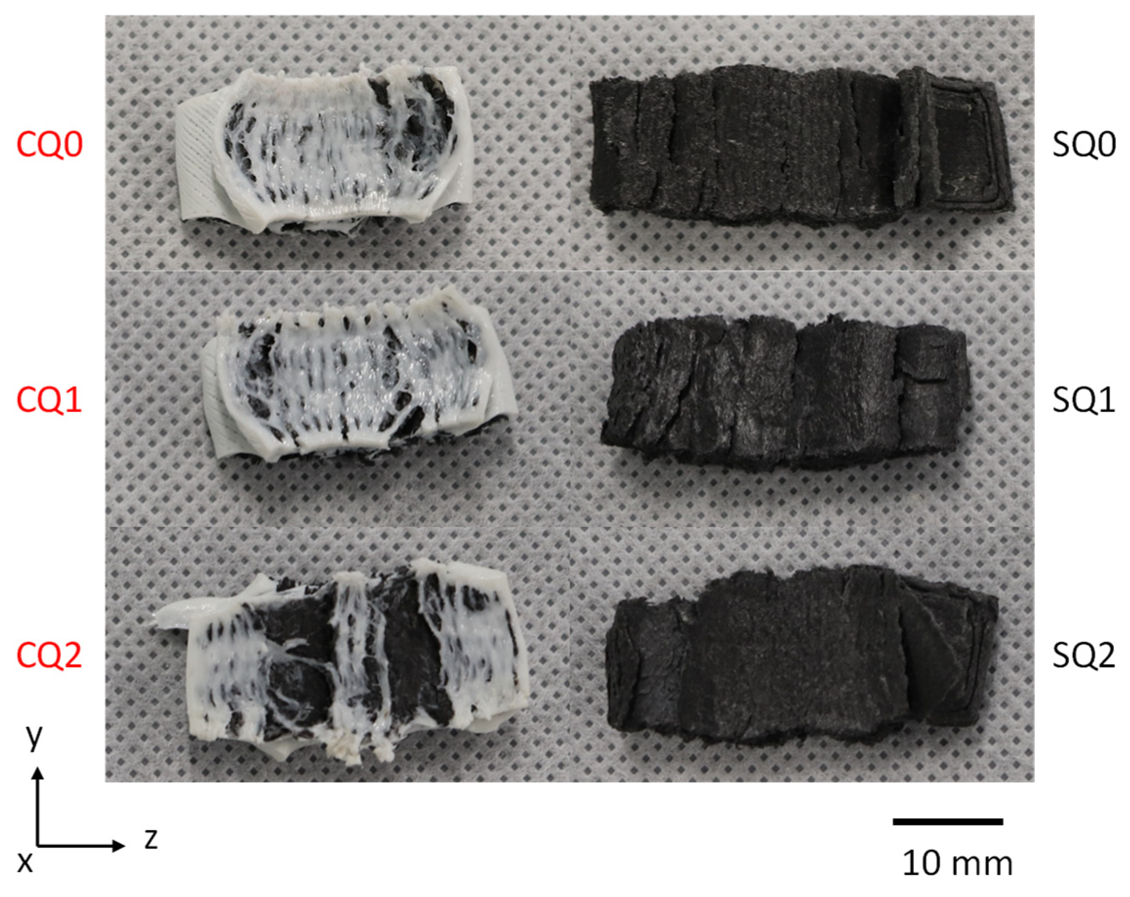
The post-experiment compression samples for different MEAM structures are presented in Figure 7. All the structures underwent elastic–plastic deformation where the structure’s response plateaued after yielding, followed by the material’s densification. The pure nylon sample flattened equally in all directions, indicating considerable isotropy for this AM polymer with good bonding between the filaments. However, the composites generally flattened more in the z-direction under compression, with SF structures demonstrating more layer separation compared to CF structures. Exposed fibres indicated weaker bonding between the adjacent printed layers, showing the influence of fibres on the deformation direction. Some studies [38,39] presented higher levels of strength and stiffness for pure nylon compared to its composites, but the post-experimental images showed buckled samples that led to premature failure and inconclusive results for the properties. To improve the predictability of compression behaviour, microstructural features such as fibre waviness, interfacial bonding and matrix deformation could be investigated to provide insights into non-linear densification and flattening mechanisms, thereby improving the accuracy of predictions. Additionally, numerical simulations based on the concept of the representative volume element (RVE) could be employed to enhance the design and optimisation of these materials. By incorporating realistic microstructural characteristics, RVE models could capture local distributions of stresses and deformation mechanisms more accurately, leading to improved predictions of constitutive behaviour under compression.

3.3. Tensile vs. Compressive Behaviour

The comparison of tension–compression performance and post-experimental images revealed that pure nylon underwent elastic–plastic deformation for both loading directions. However, the composites showed an elastic–brittle fracture under tension and elastic–plastic deformation under compression, indicating that the loading direction influenced the damage and failure behaviours of the AM composites. To determine the variation in the mechanical performance based on the loading regime, the ratios of the strengths and moduli obtained from the tension–compression tests were calculated and listed in Table 5.
The MEAM nylon showed similar yield strength for both tension and compression; however, the low modulus ratio indicates that the nylon structure was twice as stiffer under compressive load. For the NCCF composites, CL performed significantly better under a tensile load, whereas CT performed better under compression. CQ demonstrated the least strength anisotropy of the CF composites, although the structure still exhibited higher levels of strength and stiffness under tension. The SF composites demonstrated a more complex pattern, with both unidirectional orientations, SL and ST, revealing considerably higher stiffness under tensile load but higher strength under compression. SQ also had the least anisotropy for the strength ratio among NSCF composites while still having higher strength and stiffness under tension like CQ. As most MEAM composite properties were significantly better under tension, it can be concluded that the orientation of these structures should be tailored for applications to withstand loads under tension (except for CT, which should be modified for bearing compressive loads).
The quasi-isotropic specimens (a hybrid of unidirectional, 0°/90° and cross-ply +45°/−45° layers) demonstrated the lowest extent of anisotropy. This indicates that further hybridisation using additional orientation angles of fibres (such as +30°/−30° and +60°/−60°) may further lower the anisotropy. Thus, a balance between stiffness and strength across different loading directions could be achieved for such MEAM composites. Additionally, since CL showed higher tensile strength while SL showed higher compressive strength, a combination of both CF and SF layers could be fabricated to produce a hybrid composite structure. This could reduce the tension–compression asymmetry by balancing the strength for different orientations and improve the capacity of these structures for applications with complex loading regimes. The strength and stiffness ratios of these MEAM structures could also be used in advanced numerical models in future studies and reproduce the varying performance by accounting for both filament and loading directions.

3.4. Tensile Strain Rate Sensitivity

The quasi-isotropic orientations (CQ and SQ) demonstrated lower anisotropy in the mechanical tests, and a previous study [24] showed lower porosity of these structures compared to the unidirectional orientations. Therefore, these structures were further tested with increased loading speed to determine the strain rate sensitivity of these composites. The mean tensile stress–strain results for the quasi-isotropic specimens under different strain rates are presented in Figure 8. The properties calculated for each case are listed in Table 6 and compared to those for the original (lowest) strain rate, followed by Figure 9 with the post-experimental specimens.
The quasi-isotropic composites showed an overall decrease in both the tensile strength and modulus of the structures but an increase in the elongation at break with an increased strain rate. For CQ, increasing the strain rate by two orders of magnitude reduced the strength by about 14% and the stiffness by only 2.4%, with a significant increase in the elongation at break (nearly 24%). Although no pattern was found for the decrease in tensile strength of SQ with increased strain rate, the stiffness was significantly reduced (by approximately 60%), while the elongation at break was considerably increased (almost 42%) for SQ when the strain rate was increased. The strain rate affected the mechanical properties of SQ significantly more than those of CQ. Therefore, the MEAM composites, especially the SQ, were considerably more sensitive to higher strain rates under tensile load: the 100-fold increase in the strain rate resulted in a change of up to 60% in their mechanical properties. The post-experiment samples again showed an elastic–brittle fracture, indicating that the damage and failure mechanisms remained consistent with the tensile loading direction even under an increased strain rate.
Fisher et al. [38] and Vanei et al. [40] conducted strain rate sensitivity analyses for SF nylon composites with fibres oriented in the loading direction. In contrast, this study also investigated transverse and quasi-isotropic cases of fibre orientations. In these specimens, fibres were aligned in other major directions beyond the longitudinal axis, along with continuous-fibre composites, for a comprehensive assessment of strain rate-dependent behaviour across different fibre types and configurations. Both studies reported an increase in stiffness with strain rate; however, Fisher et al. [38] observed the increased strength, whereas Vanei et al. [40] reported the opposite trend without providing significant explanations for these phenomena. The microstructural analysis of MEAM composites studied here showed up to 20% porosity [24]. At higher strain rates, the time for the stress to redistribute across these weak porous interfaces decreases significantly. This leads to higher local stress (and strain) concentration and an early onset of damage, thus reducing the strength and stiffness. The high energy of deformation increased the elongation at the break of the composites. Since SQ had higher porosity, the change in mechanical properties of SQ was also larger [24]. The decreased mechanical performance with strain rate suggests these MEAM composites are unsuitable for pure tensile-load applications under high strain rates.

3.5. Compressive Strain Rate Sensitivity

The mean compressive stress vs. strain result of the quasi-isotropic orientations under different strain rates and the calculated properties are presented in Figure 10 and Table 7, respectively, while Figure 11 shows the post-compression specimens, similar to the analysis of tensile strain rate sensitivity.
Both MEAM composites demonstrated increased compressive strength with strain rate: CQ with marginally increased strength (up to 4% at two orders magnitude of higher strain rate) while SQ had a considerably higher strength increased by nearly 50% compared to the original strain rate. Although CQ similarly showed some increase in stiffness (by around 5% for the same increase in strain rate), SQ showed a significantly lower compressive stiffness (about 63%). The compressive strain rate affected the mechanical properties of SQ significantly more than those of CQ, similar to the case of tensile strain rate sensitivity analysis.
Fisher et al. [38] did not provide an explanation for the increased compressive modulus with strain rate for SF composite with a concentric pattern. In our study, the rapid compression of the structures led to earlier densification, increasing the strength of the composites with the strain rate. For CQ, this also increased the stiffness of the structures, but the high porosity in SQ [24] allowed easier and quicker compression of the structures, leading to an overall decrease in their stiffness. Similarly to the tensile strain rate sensitivity analysis, the SQ composites were also sensitive to compressive loads under high strain rates as the mechanical properties decreased by 63% for the strain rate increase by a factor of 100. The post-experiment samples again showed elastic–plastic deformation with directional flattening for all strain rate cases, further indicating the consistent damage and failure of the composites under compressive load. Unlike the tensile sensitivity analysis, CQ demonstrated increased strength and stiffness at high strain rates, making it suitable for energy-absorbing applications where compressive forces dominate, such as impact-resistant panels and helmets. On the other hand, SQ exhibited high strength but low stiffness, which could influence its deformation behaviour under impact loading. While the increased strength is beneficial, the lower stiffness may lead to excessive deformation, potentially affecting its ability to dissipate energy effectively.

4. Conclusions

The anisotropic mechanical behaviour of the MEAM polymer and its composites was investigated for the effects of fibre reinforcement, filament/fibre orientation and strain rate in tension and compression. The study revealed the following:
  • The addition of fibres enhanced the tensile and compressive performances of nylon–matrix composites. NCCF composites exhibited greater strength and stiffness than NSCF ones, particularly when fibres were aligned along the loading direction. The performance for the longitudinal orientation was the best, followed by that of quasi-isotropic specimens, with the transverse loading resulting in the worst performance. The post-experiment analysis indicated the elastic–brittle fracture.
  • The composites also demonstrated better properties than pure MEAM nylon under compression. Here, the unidirectional NCCF composites were stiffer than NSCF, with the opposite for CQ and SQ, though strength variation showed complex and unpredictable behaviours. The composites exhibited elastic–plastic deformation, significant z-direction flattening and weaker interlayer bonding than pure MEAM nylon.
  • The tension–compression anisotropy analysis revealed that CL and CQ specimens of NCCF composites performed well in tension, while CT performed better in compression. The NSCF composites were generally stiffer under tension, with SL and ST showing greater compressive strength.
  • Quasi-isotropic structures, with the lowest levels of anisotropy and porosity, were tested at varied strain rates. Increasing the tensile strain rate decreased their strength and moduli but increased the elongation at the break. However, increasing the compressive strain rate increased the strength of both. Also, the stiffness of CQ grew while the stiffness of SQ decreased. Overall, the MEAM composites, especially SQ, are sensitive to high strain rates for both loading regimes, though the deformation and failure modes remained consistent.

Author Contributions

Conceptualisation, M.N.I., K.P.B. and V.V.S.; methodology, M.N.I., K.P.B. and V.V.S.; software, M.N.I.; formal analysis, M.N.I., K.P.B. and V.V.S.; data curation, M.N.I.; investigation, M.N.I.; writing—original draft preparation, M.N.I.; writing—review and editing, K.P.B. and V.V.S.; visualisation, M.N.I.; supervision, K.P.B. and V.V.S. All authors have read and agreed to the published version of the manuscript.

Funding

This research received no external funding.

Data Availability Statement

The data supporting the conclusions of this article will be made available by the authors upon request.

Conflicts of Interest

The authors declare no conflicts of interest.

References

  1. Bikas, H.; Stavropoulos, P.; Chryssolouris, G. Additive Manufacturing Methods and Modeling Approaches: A Critical Review. Int. J. Adv. Manuf. Technol. 2016, 83, 389–405. [Google Scholar] [CrossRef]
  2. Vyavahare, S.; Teraiya, S.; Panghal, D.; Kumar, S. Fused Deposition Modelling: A Review. Rapid Prototyp. J. 2020, 26, 176–201. [Google Scholar] [CrossRef]
  3. Saleh Alghamdi, S.; John, S.; Roy Choudhury, N.; Dutta, N.K. Additive Manufacturing of Polymer Materials: Progress, Promise and Challenges. Polymers 2021, 13, 753. [Google Scholar] [CrossRef] [PubMed]
  4. Islam, M.N.; Baxevanakis, K.P.; Silberschmidt, V.V. Dynamic Fracture Behaviour of Additively Manufactured Composite Materials. In Dynamic Deformation, Damage and Fracture in Composite Materials and Structures; Silberschmidt, V., Ed.; Elsevier: Amsterdam, The Netherlands, 2023; pp. 441–488. [Google Scholar] [CrossRef]
  5. Kabir, S.M.F.; Mathur, K.; Seyam, A.F.M. Maximizing the Performance of 3D Printed Fiber-Reinforced Composites. J. Compos. Sci. 2021, 5, 136. [Google Scholar] [CrossRef]
  6. Ngo, T.D.; Kashani, A.; Imbalzano, G.; Nguyen, K.T.Q.; Hui, D. Additive Manufacturing (3D Printing): A Review of Materials, Methods, Applications and Challenges. Compos. B Eng. 2018, 143, 172–196. [Google Scholar] [CrossRef]
  7. Arefin, A.M.E.; Khatri, N.R.; Kulkarni, N.; Egan, P.F. Polymer 3D Printing Review: Materials, Process, and Design Strategies for Medical Applications. Polymers 2021, 13, 1499. [Google Scholar] [CrossRef]
  8. Salifu, S.; Desai, D.; Ogunbiyi, O.; Mwale, K. Recent Development in the Additive Manufacturing of Polymer-Based Composites for Automotive Structures—A Review. Int. J. Adv. Manuf. Technol. 2022, 119, 6877–6891. [Google Scholar] [CrossRef]
  9. Bakır, A.A.; Atik, R.; Özerinç, S. Mechanical Properties of Thermoplastic Parts Produced by Fused Deposition Modeling: A Review. Rapid Prototyp. J. 2021, 27, 537–561. [Google Scholar] [CrossRef]
  10. Parandoush, P.; Lin, D. A Review on Additive Manufacturing of Polymer-Fiber Composites. Compos. Struct. 2017, 182, 36–53. [Google Scholar] [CrossRef]
  11. Wang, X.; Jiang, M.; Zhou, Z.; Gou, J.; Hui, D. 3D Printing of Polymer Matrix Composites: A Review and Prospective. Compos. B Eng. 2017, 110, 442–458. [Google Scholar] [CrossRef]
  12. Wang, P.; Zou, B.; Xiao, H.; Ding, S.; Huang, C. Effects of Printing Parameters of Fused Deposition Modeling on Mechanical Properties, Surface Quality, and Microstructure of PEEK. J. Mater. Process. Technol. 2019, 271, 62–74. [Google Scholar] [CrossRef]
  13. Coppola, B.; Cappetti, N.; Di Maio, L.; Scarfato, P.; Incarnato, L. 3D Printing of PLA/Clay Nanocomposites: Influence of Printing Temperature on Printed Samples Properties. Materials 2018, 11, 1947. [Google Scholar] [CrossRef] [PubMed]
  14. Guessasma, S.; Belhabib, S.; Nouri, H. Effect of Printing Temperature on Microstructure, Thermal Behavior and Tensile Properties of 3D Printed Nylon Using Fused Deposition Modeling. J. Appl. Polym. Sci. 2021, 138, 50162. [Google Scholar] [CrossRef]
  15. Zotti, A.; Zuppolini, S.; Tábi, T.; Grasso, M.; Ren, G.; Borriello, A.; Zarrelli, M. Effects of 1D and 2D Nanofillers in Basalt/Poly(Lactic Acid) Composites for Additive Manufacturing. Compos. B Eng. 2018, 153, 364–375. [Google Scholar] [CrossRef]
  16. Heidari-Rarani, M.; Rafiee-Afarani, M.; Zahedi, A.M. Mechanical Characterization of FDM 3D Printing of Continuous Carbon Fiber Reinforced PLA Composites. Compos. B Eng. 2019, 175, 107147. [Google Scholar] [CrossRef]
  17. Li, L.; Liu, W.; Sun, L. Mechanical Characterization of 3D Printed Continuous Carbon Fiber Reinforced Thermoplastic Composites. Compos. Sci. Technol. 2022, 227, 109618. [Google Scholar] [CrossRef]
  18. Fernandes, R.R.; Tamijani, A.Y.; Al-Haik, M. Mechanical Characterization of Additively Manufactured Fiber-Reinforced Composites. Aerosp. Sci. Technol. 2021, 113, 106653. [Google Scholar] [CrossRef]
  19. Es-Said, O.S.; Foyos, J.; Noorani, R.; Mendelson, M.; Marloth, R.; Pregger, B.A. Effect of Layer Orientation on Mechanical Properties of Rapid Prototyped Samples. Mater. Manuf. Process. 2000, 15, 107–122. [Google Scholar] [CrossRef]
  20. Chacón, J.M.; Caminero, M.Á.; Núñez, P.J.; García-Plaza, E.; Bécar, J.P. Effect of Nozzle Diameter on Mechanical and Geometric Performance of 3D Printed Carbon Fibre-Reinforced Composites Manufactured by Fused Filament Fabrication. Rapid Prototyp. J. 2021, 27, 769–784. [Google Scholar] [CrossRef]
  21. Álvarez, K.; Lagos, R.F.; Aizpun, M. Investigating the Influence of Infill Percentage on the Mechanical Properties of Fused Deposition Modelled ABS Parts. Ing. Investig. 2016, 36, 110–116. [Google Scholar] [CrossRef]
  22. Luke, S.S.; Soares, D.; Marshall, J.V.; Sheddden, J.; Keleş, Ö. Effect of Fiber Content and Fiber Orientation on Mechanical Behavior of Fused Filament Fabricated Continuous-Glass-Fiber-Reinforced Nylon. Rapid Prototyp. J. 2021, 27, 1346–1354. [Google Scholar] [CrossRef]
  23. Kumar Mishra, P.; Jagadesh, T. Investigation into Tensile Behavior of 3D Printed Nylon-Based Low and High-Volume Fraction Carbon Fiber Composite. Rapid Prototyp. J. 2023, 29, 1679–1701. [Google Scholar] [CrossRef]
  24. Islam, M.N.; Baxevanakis, K.P.; Silberschmidt, V.V. Viscoelastic Characterisation of Additively Manufactured Composites with Nylon Matrix: Effects of Type and Orientation of Fibres. Compos. B Eng. 2023, 263, 110815. [Google Scholar] [CrossRef]
  25. Baechle-Clayton, M.; Loos, E.; Taheri, M.; Taheri, H. Failures and Flaws in Fused Deposition Modeling (FDM) Additively Manufactured Polymers and Composites. J. Compos. Sci. 2022, 6, 202. [Google Scholar] [CrossRef]
  26. Islam, M.N.; Baxevanakis, K.P.; Silberschmidt, V.V. Mechanical Characterisation of AM Nylon-Matrix Carbon-Fibre-Reinforced Composite in Tension. Mater. Today Proc. 2022, 70, 50–54. [Google Scholar] [CrossRef]
  27. de Toro, E.V.; Sobrino, J.C.; Martínez, A.M.; Eguía, V.M.; Pérez, J.A. Investigation of a Short Carbon Fibre-Reinforced Polyamide and Comparison of Two Manufacturing Processes: Fused Deposition Modelling (FDM) and Polymer Injection Moulding (PIM). Materials 2020, 13, 672. [Google Scholar] [CrossRef]
  28. Hetrick, D.R.; Sanei, S.H.R.; Bakis, C.E.; Ashour, O. Evaluating the Effect of Variable Fiber Content on Mechanical Properties of Additively Manufactured Continuous Carbon Fiber Composites. J. Reinf. Plast. Compos. 2021, 40, 365–377. [Google Scholar] [CrossRef]
  29. Peng, Y.; Wu, Y.; Wang, K.; Gao, G.; Ahzi, S. Synergistic Reinforcement of Polyamide-Based Composites by Combination of Short and Continuous Carbon Fibers via Fused Filament Fabrication. Compos. Struct. 2019, 207, 232–239. [Google Scholar] [CrossRef]
  30. Sanei, S.H.R.; Popescu, D. 3d-Printed Carbon Fiber Reinforced Polymer Composites: A Systematic Review. J. Compos. Sci. 2020, 4, 98. [Google Scholar] [CrossRef]
  31. Blok, L.G.; Longana, M.L.; Yu, H.; Woods, B.K.S. An Investigation into 3D Printing of Fibre Reinforced Thermoplastic Composites. Addit. Manuf. 2018, 22, 176–186. [Google Scholar] [CrossRef]
  32. Chacón, J.M.; Caminero, M.A.; Núñez, P.J.; García-Plaza, E.; García-Moreno, I.; Reverte, J.M. Additive Manufacturing of Continuous Fibre Reinforced Thermoplastic Composites Using Fused Deposition Modelling: Effect of Process Parameters on Mechanical Properties. Compos. Sci. Technol. 2019, 181, 107688. [Google Scholar] [CrossRef]
  33. Saeed, K.; McIlhagger, A.; Harkin-Jones, E.; McGarrigle, C.; Dixon, D.; Ali Shar, M.; McMillan, A.; Archer, E. Characterization of Continuous Carbon Fibre Reinforced 3D Printed Polymer Composites with Varying Fibre Volume Fractions. Compos. Struct. 2022, 282, 115033. [Google Scholar] [CrossRef]
  34. Islam, M.N.; Baxevanakis, K.P.; Silberschmidt, V.V. Dynamic Fracture Behaviour of Additively Manufactured Polymers and Composites under Ballistic Impact. Proc. Struct. Integr. 2021, 37, 217–224. [Google Scholar] [CrossRef]
  35. Verbeeten, W.M.H.; Arnold-Bik, R.J.; Lorenzo-Bañuelos, M. Print Velocity Effects on Strain-Rate Sensitivity of Acrylonitrile-Butadiene-Styrene Using Material Extrusion Additive Manufacturing. Polymers 2021, 13, 149. [Google Scholar] [CrossRef] [PubMed]
  36. Verbeeten, W.M.H.; Lorenzo-Bañuelos, M.; Arribas-Subiñas, P.J. Anisotropic Rate-Dependent Mechanical Behavior of Poly(Lactic Acid) Processed by Material Extrusion Additive Manufacturing. Addit. Manuf. 2020, 31, 100968. [Google Scholar] [CrossRef]
  37. Hosseini, S.A.; Torabizadeh, M.; Eisazadeh, H. Experimental Study of the Effect of Strain Rate on the Mechanical Behavior of Assorted Thermoplastic Polymers. J. Mater. Eng. Perform. 2023, 33, 6942–6951. [Google Scholar] [CrossRef]
  38. Fisher, T.; Almeida, J.H.S.; Falzon, B.G.; Kazancı, Z. Tension and Compression Properties of 3D-Printed Composites: Print Orientation and Strain Rate Effects. Polymers 2023, 15, 1708. [Google Scholar] [CrossRef]
  39. Mohammadizadeh, M.; Gupta, A.; Fidan, I. Mechanical Benchmarking of Additively Manufactured Continuous and Short Carbon Fiber Reinforced Nylon. J. Compos. Mater. 2021, 55, 3629–3638. [Google Scholar] [CrossRef]
  40. Vanaei, H.R.; El Magri, A.; Rastak, M.A.; Vanaei, S.; Vaudreuil, S.; Tcharkhtchi, A. Numerical–Experimental Analysis toward the Strain Rate Sensitivity of 3D-Printed Nylon Reinforced by Short Carbon Fiber. Materials 2022, 15, 8722. [Google Scholar] [CrossRef]
  41. Markforged Inc. Material Specifications; Markforged Inc.: Watertown, MA, USA, 2021. [Google Scholar]
  42. Lay, M.; Thajudin, N.L.N.; Hamid, Z.A.A.; Rusli, A.; Abdullah, M.K.; Shuib, R.K. Comparison of Physical and Mechanical Properties of PLA, ABS and Nylon 6 Fabricated Using Fused Deposition Modeling and Injection Molding. Compos. B Eng. 2019, 176, 107341. [Google Scholar] [CrossRef]
  43. ASTM 638-14; Standard Test Method for Tensile Properties of Plastics. ASTM International: West Conshohocken, PA, USA, 2006; pp. 1–15. [CrossRef]
  44. ASTM D695-15; Standard Test Method for Compressive Properties of Rigid Plastics. ASTM International: West Conshohocken, PA, USA, 2010; pp. 1–8. [CrossRef]
  45. Economides, A.L.; Islam, M.N.; Baxevanakis, K.P. Additively Manufactured Carbon Fibre PETG Composites: Effect of Print Parameters on Mechanical Properties. Polymers 2024, 16, 3336. [Google Scholar] [CrossRef] [PubMed]
Figure 1. Cross-section optical microscopy of NSCF (a) and NCCF (b) filaments.
Jcs 09 00186 g001
Figure 2. Stacking order and print orientation of NSCF (a) and NCCF (b) filaments.
Jcs 09 00186 g002
Figure 3. Print orientation showing last layer and testing direction of MEAM composite tensile (a) and compressive (c) test samples. Fabricated quasi-isotropic NSCF (black) and NCCF (white) composites tensile (b) and compressive test samples (d).
Jcs 09 00186 g003
Figure 4. Tensile stress–strain curves for MEAM composites (shaded regions represent variations in test data).
Jcs 09 00186 g004
Figure 5. Post-experimental tensile test specimens of MEAM structures.
Jcs 09 00186 g005
Figure 6. Compressive stress–strain curves for MEAM composites (shaded regions represent variation in test data).
Jcs 09 00186 g006
Figure 7. Post-experimental compressive specimens of MEAM structures.
Jcs 09 00186 g007
Figure 8. Tensile stress–strain curves for MEAM quasi-static composites at different strain rates (shaded regions represent variation in test data).
Jcs 09 00186 g008
Figure 9. Post-tensile specimen of quasi-isotropic composites after tests at different strain rates.
Jcs 09 00186 g009
Figure 10. Compressive stress–strain curves for MEAM quasi-static composites at different strain rates (shaded regions represent variation in test data).
Jcs 09 00186 g010
Figure 11. Post-compressive specimen of quasi-isotropic composites after tests at different strain rates.
Jcs 09 00186 g011
Table 1. Printing parameters for studied MEAM composites.
Printing ParametersNSCFNCCF
MaterialsMixedNylonCarbon fibre
Nozzle temperature260 °C260 °C260 °C
Nozzle diameter0.8 mm0.4 mm0.9 mm
Layer height0.125 mm0.125 mm0.125 mm
Table 2. Print layup of MEAM structures (notation of each structural configuration in brackets).
Stacking OrderNSCFNCCF
MaterialsMixedNylonCarbon fibre
Pure nylonN/A[45°, −45°] (N)N/A
Longitudinal[0°] (SL)[45°, −45°][0°] (CL)
Transverse[90°] (ST)[45°, −45°][90°] (CT)
Quasi-isotropic[0°, 45°, 90°, −45°] (SQ)[45°, −45°][0°, 45°, 90°, −45°] (CQ)
Table 3. Tensile test data for studied MEAM structures (standard deviation in brackets).
MEAM StructureTensile Modulus (GPa)Tensile Strength (MPa)Elongation at Break (%)
N0.46 (0.01)Yield—28.25 (0.93)554.03 (13.76)
CL13.45 (0.90)145.54 (8.88)1.05 (0.07)
SL5.91 (0.52)78.91 (4.27)2.89 (0.21)
CT0.99 (0.10)31.70 (1.03)26.21 (1.65)
ST1.81 (0.10)50.00 (1.96)8.30 (0.27)
CQ5.45 (0.38)89.06 (4.60)1.63 (0.11)
SQ3.51 (0.27)67.61 (2.20)6.57 (0.55)
Table 4. Compressive test data for MEAM structures (standard deviation in brackets).
MEAM StructureCompressive Modulus (GPa)Compressive Yield Strength (MPa)
N1.00 (0.78)28.02 (5.05)
CL2.34 (0.08)62.34 (0.81)
SL1.37 (0.41)121.28 (2.45)
CT1.55 (0.13)44.59 (1.12)
ST1.20 (0.10)59.16 (2.78)
CQ2.20 (0.16)69.85 (1.06)
SQ2.30 (0.12)58.94 (4.31)
Table 5. Strength and moduli ratio for MEAM structures.
MEAM StructureRatio of Tensile Modulus to Compressive ModulusRatio of Tensile Strength to Compressive Yield Strength
N0.461.01
CL5.172.33
SL4.310.65
CT0.640.71
ST1.510.85
CQ2.481.28
SQ1.531.15
Table 6. Tensile-test results for the MEAM quasi-static structures at different strain rates (standard deviation in brackets).
MEAM StructureSQ0SQ1SQ2CQ0CQ1CQ2
Strain rate (s−1)0.0030.030.30.0030.030.3
Tensile modulus (GPa)3.51 (0.27)2.15 (0.18)1.40 (0.08)5.45 (0.38)5.40 (0.28)5.32 (0.02)
Difference in modulus to original strain rate (%)−38.75−60.11−0.92−2.39
Tensile strength (MPa)67.61 (2.20)52.38 (3.90)59.12 (2.95)89.06 (4.60)85.79 (4.15)76.38 (1.31)
Difference in strength to original strain rate (%)−22.53−12.56−3.67−14.24
Elongation at break (%)6.57 (0.55)8.66 (0.36)9.32 (0.44)1.63 (0.11)1.67 (0.17)2.02 (0.07)
Difference in elongation at break to original strain rate (%)31.8141.862.4523.93
Table 7. Compressive test results for MEAM quasi-static structures at different strain rates (standard deviation in brackets).
MEAM StructureSQ0SQ1SQ2CQ0CQ1CQ2
Strain rate (s−1)0.0010.010.10.0010.010.1
Compressive modulus (GPa)2.30 (0.12)0.79 (0.06)0.85 (0.05)2.20 (0.16)2.28 (0.13)2.31 (0.04)
Difference in modulus to original strain rate (%)−65.65−63.043.645.00
Compressive strength (MPa)58.94 (4.31)83.37 (0.57)88.25 (0.74)69.85 (1.06)71.05 (2.51)72.56 (3.23)
Difference in strength to original strain rate (%)41.4549.731.723.88
Disclaimer/Publisher’s Note: The statements, opinions and data contained in all publications are solely those of the individual author(s) and contributor(s) and not of MDPI and/or the editor(s). MDPI and/or the editor(s) disclaim responsibility for any injury to people or property resulting from any ideas, methods, instructions or products referred to in the content.

