
Development of Cement-Free Binder Systems Based on Metallurgical Waste: Hardening by Forced Carbonation

 ,
,  and
and 
Abstract
1. Introduction
2. Materials and Methods
- -
- BOF slag from Cherepovets Steel Mill of the public joint stock company “Severstal” (CherSM PJSC “Severstal”) with an initial particle size 5–30 mm (hereafter BOF slag);
- -
- Slag from the electric arc furnace of the A.A. Ugarov Oskol Electrometallurgical Plant JSC. LLC MC Metalloinvest with an initial particle size of 0.16–10 mm (hereafter referred to as EAF slag);
- -
- Nepheline sludge, which is a large-tonnage byproduct of producing alumina using the alkaline method from nepheline concentrates of the Kolsky Peninsula of LLC Pikalevsky Alumina Plant, with an initial particle size of 0.16–2 mm (hereafter referred to as BS slag). A general view of the initial slags under consideration is presented in Figure 1.
3. Results
4. Conclusions
Author Contributions
Funding
Data Availability Statement
Conflicts of Interest
References
- IPCC. IPCC Special Report on Climate Change, Desertification, Land Degradation, Sustainable Land Management, Food Security, and Greenhouse Gas Fluxes in Terrestrial Ecosystems; IPCC: Geneva, Switzerland, 2019. [Google Scholar]
- Schneider, T.; Kaul, C.M.; Pressel, K.G. Possible climate transitions from breakup of stratocumulus decks under greenhouse warming. Nat. Geosci. 2019, 12, 163–167. [Google Scholar] [CrossRef]
- Ekdahl, Å. Climate Change and the Production of Iron and Steel: An Industry View; World Steel Association: Brussels, Belgium, 2021. [Google Scholar]
- Jiang, Y.; Ling, T.C.; Shi, C.; Pan, S.Y. Characteristics of steel slags and their use in cement and concrete—A review. Resour. Conserv. Recycl. 2018, 136, 187–197. [Google Scholar] [CrossRef]
- Mo, L.; Zhang, F.; Deng, M.; Jin, F.; Al-Tabbaa, A.; Wang, A. Accelerated carbonation and performance of concrete made with steel slag as binding materials and aggregates. Cem. Concr. Compos. 2017, 83, 138–145. [Google Scholar] [CrossRef]
- Ukwattage, N.L.; Ranjith, P.G.; Li, X. Steel-making slag for mineral sequestration of carbon dioxide by accelerated carbonation. Meas. J. Int. Meas. Confed. 2017, 97, 15–22. [Google Scholar] [CrossRef]
- Humbert, P.S.; Castro-Gomes, J. CO2 activated steel slag-based materials: A review. J. Clean. Prod. 2019, 208, 448–457. [Google Scholar] [CrossRef]
- Pan, L.S.Y.; Adhikari, R.; Chen, Y.H.; Li, P.; Chiang, P.C. Integrated and innovative steel slag utilization for iron reclamation, green material production and CO2 fixation via accelerated carbonation. J. Clean. Prod. 2016, 137, 617–631. [Google Scholar] [CrossRef]
- Mahoutian, M.; Ghouleh, Z.; Shao, Y. Carbon dioxide activated ladle slag binder. Constr. Build. Mater 2014, 66, 214–221. [Google Scholar] [CrossRef]
- Siriwardena, D.P. Quantification of CO2 sequestration capacity and carbonation rate of alkaline industrial byproducts. Constr. Build. Mater. 2015, 19, 216–224. [Google Scholar] [CrossRef]
- Yadav, S.; Mehra, A. Experimental study of dissolution of minerals and CO2 sequestration in steel slag. Waste Manag. 2017, 64, 348–357. [Google Scholar] [CrossRef]
- Bakhtin, A.; Lyubomirskiy, N.; Fic, S.; Bakhtina, T. Influence of Forced Carbonisation on the Binding Properties of Sludge with a High β-Belite Content. Materials 2021, 14, 7899. [Google Scholar] [CrossRef]
- Na, H.; Wang, Y.; Zhang, X.; Li, J.; Zeng, Y.; Liu, P. Hydration Activity and Carbonation Characteristics of Dicalcium Silicate in Steel Slag: A Review. Metals 2021, 11, 1580. [Google Scholar] [CrossRef]
- Mo, L.; Zhang, F.; Deng, M. Mechanical performance and microstructure of the calcium carbonate binders produced by carbonating steel slag paste under CO2 curing. Cem. Concr. Res. 2016, 88, 217–226. [Google Scholar] [CrossRef]
- Santos, R.M.; Van Bouwel, J.; Vandevelde, E.; Mertens, G.; Elsen, J.; Van Gerven, T. Accelerated mineral carbonation of stainless steel slags for CO2 storage and waste valorization: Effect of process parameters on geochemical properties. Int. J. Greenh. Gas. Con. 2013, 17, 32–45. [Google Scholar] [CrossRef]
- Salman, M.; Cizer, Ö.; Pontikes, Y.; Santos, R.M.; Snellings, R.; Vandewalle, L.; Blanpain, B.; Van Balen, K. Effect of accelerated carbonation on and stainless steel slag for its valorisation as a CO2-sequestering construction material. Chem. Eng. J. 2014, 246, 39–52. [Google Scholar] [CrossRef]
- Kaliyavaradhan, S.K.; Ling, T.-C.; Mo, K.H. Valorization of waste powders from cement-concrete life cycle: A pathway to circular future. J. Clean. Prod. 2020, 268, 122358. [Google Scholar] [CrossRef]
- Mehdizadeh, H.; Jia, X.; Mo, K.H.; Ling, T.-C. Effect of water-to-cement ratio induced hydration on the accelerated carbonation of cement pastes. Environ. Pollut. 2021, 280, 116914. [Google Scholar] [CrossRef]
- Wang, L.; Chen, L.; Tsang, D.C.W.; Guo, B.; Yang, J.; Shen, Z.; Hou, D.; Ok, Y.S.; Poon, C.S. Biochar as green additives in cement-based composites with carbon dioxide curing. J. Clean. Prod. 2020, 258, 20678. [Google Scholar] [CrossRef]
- Liu, Y.; Zhuge, Y.; Chow, C.W.K.; Keegan, A.; Pham, P.N.; Li, D.; Qian, G.; Wang, L. Recycling drinking water treatment sludge into eco-concrete blocks with CO2 curing: Durability and leachability. Sci. Total Environ. 2020, 746, 141182. [Google Scholar] [CrossRef]
- Boone, M.A.; Nielsen, P.; De Kock, T.; Boone, M.N.; Quaghebeur, M.; Cnudde, V. Monitoring of stainless-steel slag carbonation using X-ray computed microtomography. Environ. Sci. Technol. 2014, 48, 674–680. [Google Scholar] [CrossRef]
- Huijgen, W.J.; Witkamp, G.J.; Comans, R.N. Mineral CO2 sequestration by steel slag carbonation. Environ. Sci. Technol. 2005, 39, 9676–9682. [Google Scholar] [CrossRef]
- Ghouleh, Z.; Guthrie, R.I.L.; Shao, Y. High-strength KOBM steel slag binder activated by carbonation. Constr. Build. Mater. 2015, 99, 175–183. [Google Scholar] [CrossRef]
- Humbert, P.S.; Castro-Gomes, J.P.; Savastano, H. Clinker-free CO2 cured steel slag based binder: Optimal conditions and potential applications. Constr. Build. Mater. 2019, 210, 413–421. [Google Scholar] [CrossRef]
- Huijgen, W.J.J.; Ruijg, G.J.; Comans, R.N.J.; Witkamp, G.-J. Energy Consumption and Net CO2 Sequestration of Aqueous Mineral Carbonation. Ind. Eng. Chem. Res. 2006, 45, 9184–9194. [Google Scholar] [CrossRef]
- Polettini, A.; Pomi, R.; Stramazzo, A. Carbon sequestration through accelerated carbonation of BOF slag: Influence of particle size characteristics. Chem. Eng. J. 2016, 298, 26–35. [Google Scholar] [CrossRef]
- Chang, E.E.; Pan, S.Y.; Chen, Y.H.; Chu, H.W.; Wang, C.F.; Chiang, P.C. CO2 sequestration by carbonation of steelmaking slags in an autoclave reactor. J. Hazar. Mater. 2011, 195, 107–114. [Google Scholar] [CrossRef]
- Lee, S.; Kim, J.W.; Chae, S.; Bang, J.H.; Lee, S.W. CO2 sequestration technology through mineral carbonation: An extraction and carbonation of blast slag. J. CO2 Utiliz. 2016, 16, 336–345. [Google Scholar] [CrossRef]
- Librandi, P.; Costa, G.; Souza, A.; Stendardo, S.; Luna, A.S.; Baciocchia, R. Carbonation of steel slag: Testing of the wet route in a pilot-scale reactor. Energy Procedia. 2017, 114, 5381–5392. [Google Scholar] [CrossRef]
- Sun, H.; Wu, C.; Shen, B.; Zhang, X. Progress in the development and application of CaO-based adsorbents for CO2 capture–A review. Mater Today Sustain. 2018, 1–2, 1–27. [Google Scholar] [CrossRef]
- Huang, X.; Hu, S.; Wang, F.; Liu, Y.; Mu, Y. Properties of alkali-activated slag with addition of cation exchange material. Constr. Build. Mater. 2017, 146, 321–328. [Google Scholar] [CrossRef]
- Song, Q.; Guo, M.Z.; Wang, L.; Ling, T.C. Use of steel slag as sustainable construction materials: A review of accelerated carbonation treatment. Resour. Conserv. Recycl. 2021, 173, 105740. [Google Scholar] [CrossRef]
- Baras, A.; Li, J.; Ni, W.; Hussain, Z.; Hitch, M. Evaluation of Potential Factors Affecting Steel Slag Carbonation. Processes 2023, 11, 2590. [Google Scholar] [CrossRef]
- Lyubomirskiy, N.; Bakhtin, A.; Fic, S.; Szafraniec, M.; Bakhtina, T. Intensive Ways of Producing Carbonate Curing Building Materials Based on Lime Secondary Raw Materials. Materials 2020, 13, 2304. [Google Scholar] [CrossRef] [PubMed]
- Lyubomirskiy, N.; Bakhtina, T.; Bakhtin, A.; Fedorkin, S. The carbonate hardening lime construction material properties formation during their long-term storage and use under normal conditions. Mater. Sci. Forum. 2019, 974, 187–194. [Google Scholar] [CrossRef]
- Bakhtina, T.A.; Lyubomirskiy, N.V.; Bakhtin, A.S.; Bilenko, G.R.; Tyunyukov, I.A. Development of binder based on phosphogypsum hardening by mixed type. Vestnik MGSU 2024, 19, 1301–1316. (In Russian) [Google Scholar] [CrossRef]
- Nalimov, V.V.; Chernova, N.A. Statistical Methods of Planning Extreme Experiments; Nauka: Moscow, Russia, 1965; 340p. (In Russian) [Google Scholar]
- Ermakov, S.M.; Jigkyavskiy, A.A. The Mathematical Theory of Optimal Experiment; Nauka: Moscow, Russia, 1987; 318p. (In Russian) [Google Scholar]
- Mu, Y.; Liu, Z.; Wang, F.; Huang, X. Carbonation characteristics of γ-dicalcium silicate for low-carbon building material. Constr. Build. Mater. 2018, 177, 322–331. [Google Scholar] [CrossRef]
- Ashraf, W.; Olek, J.; Sahu, S. Phase evolution and strength development during carbonation of low-lime calcium silicate cement (CSC). Constr. Build. Mater. 2019, 210, 473–482. [Google Scholar] [CrossRef]
- Wang, D.; Chang, J. Comparison on accelerated carbonation of β-C2S, Ca(OH)2, and C4AF: Reaction degree, multi-properties, and products. Constr. Build. Mater. 2019, 224, 336–347. [Google Scholar] [CrossRef]
- GOST 17608-2017; Concrete Paving Slabs. Specifications. GOST R: Moscow, Russia, 2017.
- GOST 379-2015; Silicate Bricks, Stones, Blocks and Partition Blocks. GOST R: Moscow, Russia, 2015.


| No. | Factors | Control in the Technological Cycle |
|---|---|---|
| 1 | Slag phase composition | Raw material requirements |
| 2 | Particle size | Raw material requirements |
| 3 | Chemical additives (activators, catalysts) | Raw material requirements |
| 4 | Parameters of forming materials, products | Forming condition |
| 5 | The water content of the molding mixture (W/T) | Forming condition |
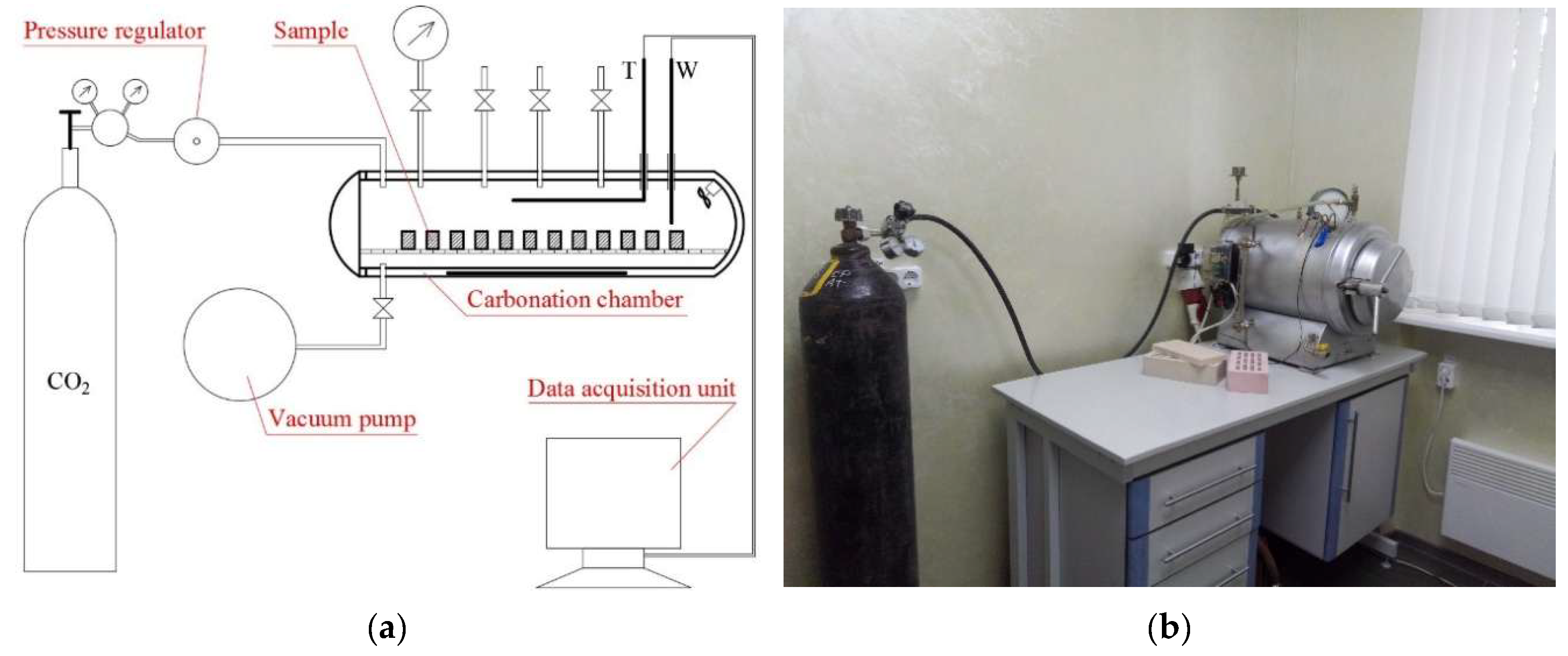
| 6 | Carbonization temperature | Forced carbonization conditions |
| 7 | Carbonization time | Forced carbonization conditions |
| 8 | CO2 pressure | Forced carbonization conditions |
| 9 | CO2 concentration | Forced carbonization conditions |
| 10 | Relative humidity | Forced carbonization conditions |
| 11 | pH of the environment | Forced carbonization conditions |
| Name of Slag | Content if Recalculated as Oxides (%) | |||||||||||
|---|---|---|---|---|---|---|---|---|---|---|---|---|
| CaO | MgO | SiO2 | Al2O3 | Fe2O3 | Na2O | K2O | MnO | TiO2 | Cr2O3 | SO3 | Total (%) | |
| BOF | 45.88 | 5.38 | 20.22 | 5.44 | 17.65 | - | 0.30 | 2.22 | 1.07 | 0.34 | 0.76 | 99.26 |
| EAF | 41.48 | 8.76 | 25.63 | 5.29 | 16.82 | - | 0.09 | 0.77 | 0.31 | 0.37 | 0.23 | 99.75 |
| BS | 62.07 | 1.27 | 28.79 | 3.77 | 2.45 | 0.38 | 0.86 | 0.08 | 0.32 | - | - | 99.99 |
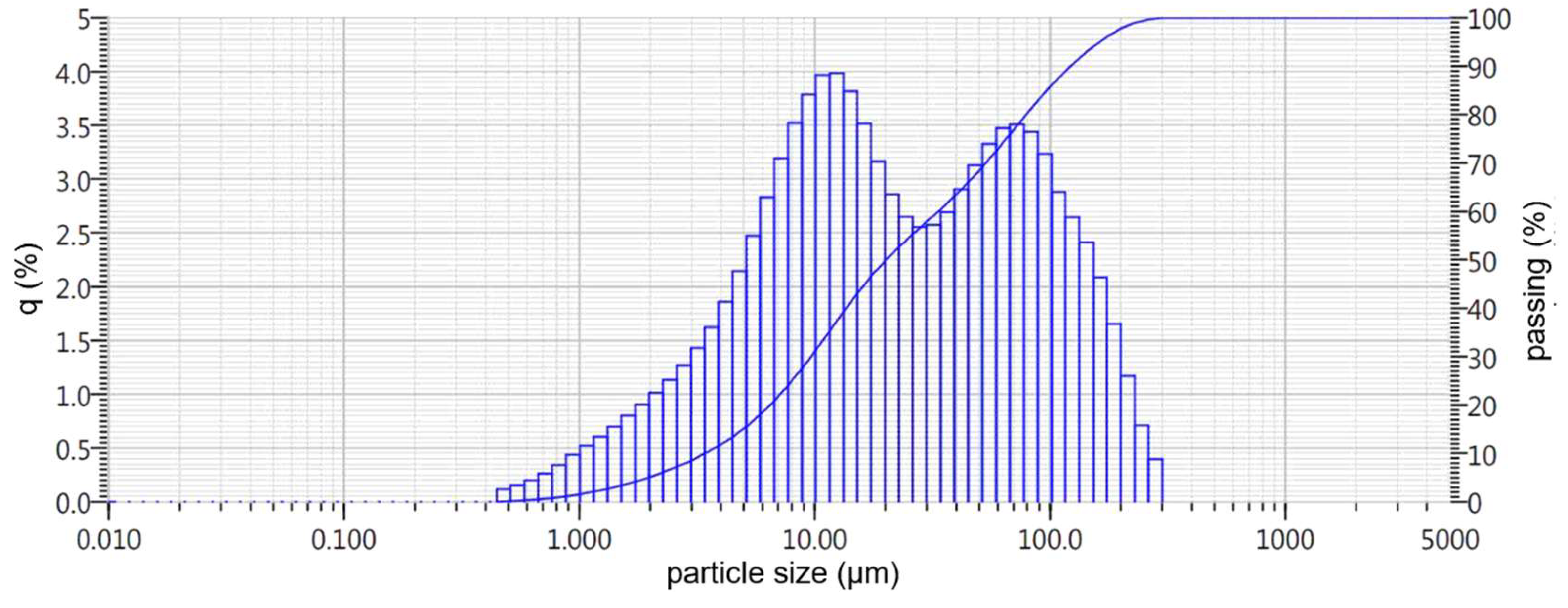
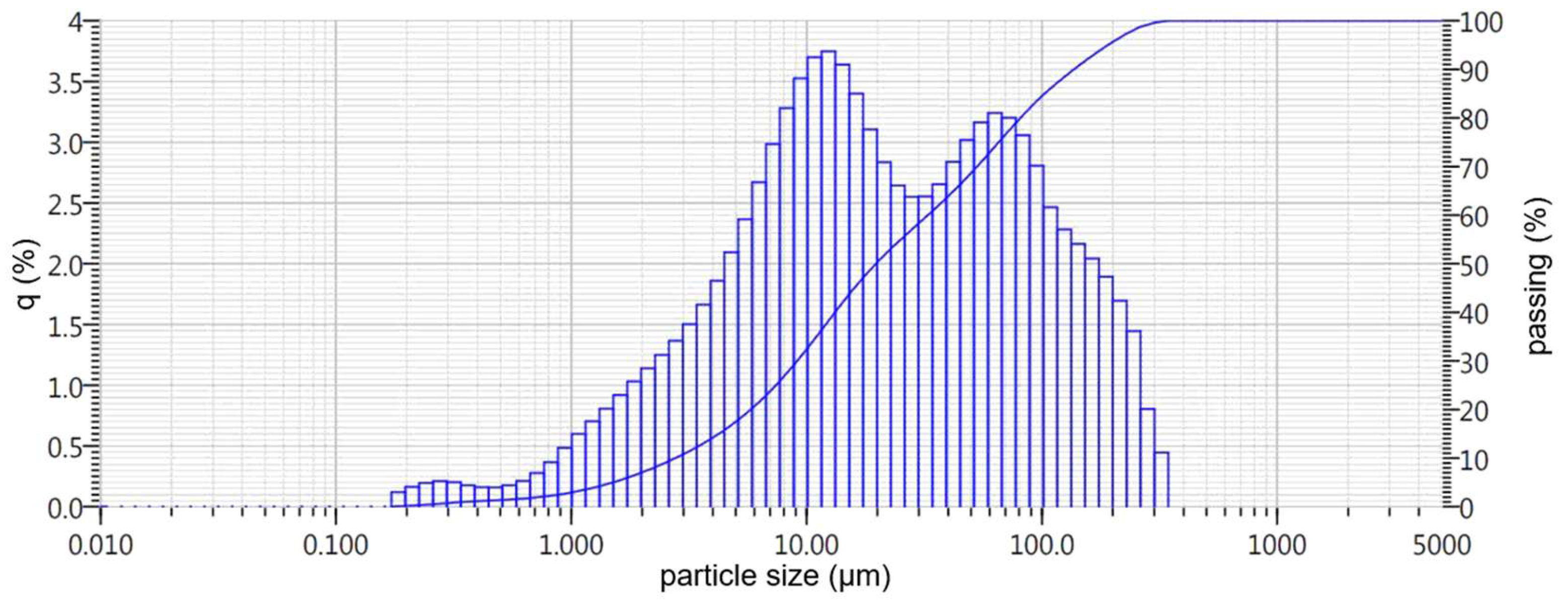
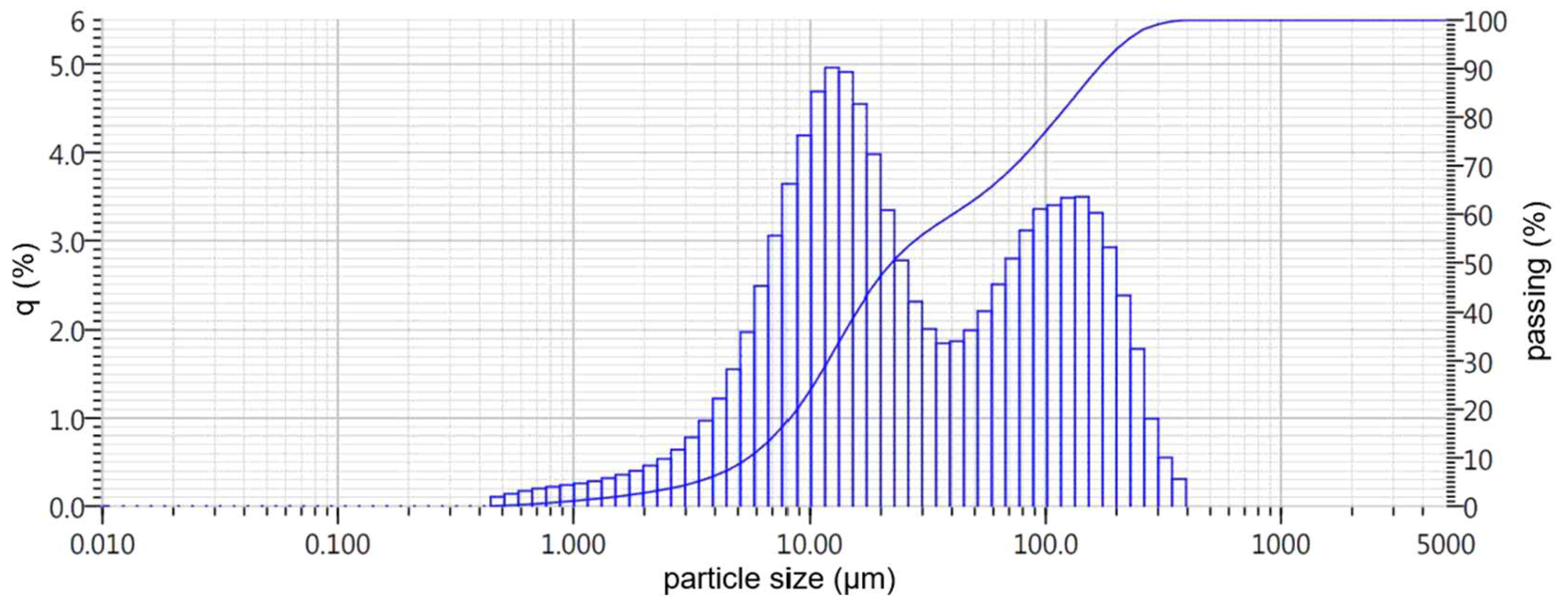
| Name of Slag | Particle Size, µm | Average Geometric Particle Size, µm | ||||||||
|---|---|---|---|---|---|---|---|---|---|---|
| ≤1.0 | ≤2.0 | ≤4.0 | ≤10.0 | ≤20.0 | ≤50.0 | ≤100.0 | ≤200.0 | ≤300.0 | ||
| BOF | 1.5 | 5.1 | 11.5 | 31.2 | 50.0 | 68.5 | 86.0 | 97.7 | 100.0 | 21.0 |
| EAF | 0.5 | 7.0 | 14.0 | 32.5 | 50.5 | 68.5 | 84.0 | 95.6 | 100.0 | 19.8 |
| BS | 1.1 | 2.7 | 6.1 | 24.0 | 48.0 | 63.0 | 77.0 | 94.0 | 100.0 | 27.3 |
| Factor | Unit of Measurement | Code | Variation Levels | Variation Interval | ||||
|---|---|---|---|---|---|---|---|---|
| −1.682 | −1 | 0 | 1 | 1.682 | ||||
| Pressing pressure | MPa | Z1 | 3.18 | 10.0 | 20.0 | 30.0 | 36.82 | 10.0 |
| Water content of the mixture | % | Z2 | 4.95 (1.95) | 7.0 (4.0) | 10.0 (7.0) | 13.0 (10.0) | 15.05 (12.05) | 3.0 |
| Carbonization time | min | Z3 | 49.08 | 90.0 | 150.0 | 210.0 | 250.92 | 60.0 |
| No. | Plan of Experiment | ||||||
|---|---|---|---|---|---|---|---|
| Point Groups | Planning Matrix | Natural Values of Variables | |||||
| Z1 | Z2 | Z3 | Pressing Pressure of the Mixture (MPa) | Water Content of the Mixture (%) | Forced Carbonization Time (min) | ||
| 1 | Nφ (cube points) | −1 | −1 | −1 | 10.00 | 7.00 (4.00) | 90.00 |
| 2 | 1 | −1 | −1 | 30.00 | 7.00 (4.00) | 90.00 | |
| 3 | −1 | 1 | −1 | 10.00 | 13.00 (10.00) | 90.00 | |
| 4 | 1 | 1 | −1 | 30.00 | 13.00 (10.00) | 90.00 | |
| 5 | −1 | −1 | 1 | 10.00 | 7.00 (4.00) | 210.00 | |
| 6 | 1 | −1 | 1 | 30.00 | 7.00 (4.00) | 210.00 | |
| 7 | −1 | 1 | 1 | 10.00 | 13.00 (10.00) | 210.00 | |
| 8 | 1 | 1 | 1 | 30.00 | 13.00 (10.00) | 210.00 | |
| 9 | Nα (star points) | −1.682 | 0 | 0 | 3.18 | 10.00 (7.00) | 150.00 |
| 10 | 1.682 | 0 | 0 | 36.82 | 10.00 (7.00) | 150.00 | |
| 11 | 0 | −1.682 | 0 | 20.00 | 4.95 (1.95) | 150.00 | |
| 12 | 0 | 1.682 | 0 | 20.00 | 15.05 (12.05) | 150.00 | |
| 13 | 0 | 0 | −1.682 | 20.00 | 10.00 (7.00) | 49.08 | |
| 14 | 0 | 0 | 1.682 | 20.00 | 10.00 (7.00) | 250.92 | |
| 15 | N0 (center points) | 0 | 0 | 0 | 20.00 | 10.00 (7.00) | 150.00 |
| 16 | 0 | 0 | 0 | 20.00 | 10.00 (7.00) | 150.00 | |
| 17 | 0 | 0 | 0 | 20.00 | 10.00 (7.00) | 150.00 | |
| 18 | 0 | 0 | 0 | 20.00 | 10.00 (7.00) | 150.00 | |
| 19 | 0 | 0 | 0 | 20.00 | 10.00 (7.00) | 150.00 | |
| 20 | 0 | 0 | 0 | 20.00 | 10.00 (7.00) | 150.00 | |
| Weight (%) | ||||
|---|---|---|---|---|
| Phase | Formula | BOF | EAF | BS |
| Okermanite | Ca2(Mg0.50Fe0.20Al0.30)(Fe0.25Al0.21)Si1.54O7 | 61.5 | - | - |
| γ-Belite (Shannonite) | γ-Ca2SiO4 | 23.6 | 11.0 | - |
| β-Belite (Larnite) | β-Ca2SiO4 | - | - | 90.0 |
| Merwinite | Ca3Mg(SiO4)2 | - | 30.0 | - |
| Hedenbergite | CaFeSi2O6 | - | 9.0 | - |
| Fayalite | γ-Fe2SiO4 | - | 11.0 | - |
| No. g | Variable Factors in the Natural Expression | Optimized Sample Parameters | |||||||||||
|---|---|---|---|---|---|---|---|---|---|---|---|---|---|
| Z1 (MPa) | Z2 (%) | Z3 (min) | Non-Carbonized | Carbonized | |||||||||
| Rc (MPa) | ρo (kg/m3) | P (%) | Rc (MPa) | ρo (kg/m3) | mCO2 (%) | P (%) | KS | Wm (%) | Wv (%) | ||||
| 1 | 10.00 | 4.00 | 90.00 | Destroyed in the drying | 2338 | 33.5 | 36.8 | 2445 | 4.8 | 28.8 | 1.00 | 10.9 | 26.5 |
| 2 | 30.00 | 4.00 | 90.00 | 2487 | 29.4 | 78.1 | 2615 | 5.0 | 23.7 | 0.84 | 8.3 | 21.6 | |
| 3 | 10.00 | 10.00 | 90.00 | 2409 | 32.1 | 65.7 | 2526 | 6.9 | 24.6 | 0.59 | 8.6 | 21.6 | |
| 4 | 30.00 | 10.00 | 90.00 | 2558 | 28.5 | 74.3 | 2664 | 6.0 | 20.6 | 0.59 | 6.9 | 18.4 | |
| 5 | 10.00 | 4.00 | 210.00 | 2346 | 33.6 | 47.4 | 2448 | 5.1 | 27.9 | 0.68 | 10.6 | 25.8 | |
| 6 | 30.00 | 4.00 | 210.00 | 2515 | 29.5 | 81.7 | 2616 | 5.2 | 22.8 | 0.72 | 8.3 | 21.7 | |
| 7 | 10.00 | 10.00 | 210.00 | 2402 | 31.6 | 66.6 | 2542 | 7.4 | 24.4 | 0.60 | 8.3 | 21.0 | |
| 8 | 30.00 | 10.00 | 210.00 | 2542 | 27.8 | 93.8 | 2689 | 7.4 | 19.4 | 0.70 | 6.3 | 16.8 | |
| 9 | 3.18 | 7.00 | 150.00 | 2183 | 38.0 | 27.3 | 2286 | 7.0 | 32.1 | 0.59 | 12.4 | 28.2 | |
| 10 | 36.82 | 7.00 | 150.00 | 2529 | 27.4 | 99.8 | 2681 | 7.0 | 19.5 | 0.73 | 6.5 | 17.4 | |
| 11 | 20.00 | 1.95 | 150.00 | 2442 | 30.4 | 29.2 | 2504 | 3.3 | 27.5 | 0.73 | 10.6 | 26.5 | |
| 12 | 20.00 | 12.05 | 150.00 | 2585 | 27.2 | - ** | 2583 | 1.7 | 26.1 | - ** | - ** | - ** | |
| 13 | 20.00 | 7.00 | 49.08 | 2446 | 30.8 | 74.0 | 2563 | 6.0 | 24.0 | 0.60 | 8.4 | 21.6 | |
| 14 | 20.00 | 7.00 | 250.92 | 2574 | 30.6 | 79.2 | 2574 | 6.6 | 22.5 | 0.66 | 8.0 | 20.6 | |
| 15 * | 20.00 | 7.00 | 150.00 | 2453 | 30.1 | 80.2 | 2587 | 6.6 | 22.8 | 0.66 | 7.9 | 20.3 | |
| Coefficient | Coefficients of ES Models of the Studied Parameters | ||||||
|---|---|---|---|---|---|---|---|
| Rc, MPa | ρo (kg/m3) | mCO2 (%) | P (%) | KS | Wm (%) | Wv (%) | |
| b0 | 76.6 | 2576.7 | 6.57 | 22.9 | 0.69 | 8.0 | 20.6 |
| b1 | 34.1 | 188.5 | −0.09 | −5.91 | 0.03 | −2.7 | −5.1 |
| b2 | 2.1 | 62.9 | 0.74 | −2.42 | −0.13 | −1.19 | −2.4 |
| b3 | 6.3 | 9.3 | 0.50 | −0.83 | −0.03 | −0.28 | −0.66 |
| b11 | −2.4 | −50.3 | 0.59 | 1.46 | 0.00 | 0.60 | 0.72 |
| b22 | −35.5 | −7.9 | −2.58 | 2.17 | 0.03 | 1.42 | 3.63 |
| b33 | 6.8 | 9.8 | 0.14 | −0.33 | −0.02 | −0.25 | −0.48 |
| b12 | −9.9 | −13.3 | −0.33 | 0.34 | 0.06 | 0.30 | 0.41 |
| b13 | 2.9 | 7.8 | 0.23 | 0.22 | 0.08 | 0.00 | −0.05 |
| b23 | 1.6 | 9.3 | 0.36 | 0.09 | 0.14 | −0.17 | −0.35 |
| No. g | Variable Factors in the Natural Expression | Optimized Sample Parameters | |||||||||||
|---|---|---|---|---|---|---|---|---|---|---|---|---|---|
| Z1 (MPa) | Z2 (%) | Z3 (min) | Non-Carbonized | Carbonized | |||||||||
| Rc (MPa) | ρo (kg/m3) | P (%) | Rc (MPa) | ρo (kg/m3) | mCO2 (%) | P (%) | KS | Wm (%) | Wv (%) | ||||
| 1 | 10.00 | 7.00 | 90.00 | 2.7 | 1958 | 37.4 | 57.0 | 2112 | 7.2 | 29.1 | 0.8 | 13.2 | 27.7 |
| 2 | 30.00 | 7.00 | 90.00 | 4.8 | 2076 | 33.1 | 86.5 | 2263 | 7.3 | 24.5 | 0.9 | 10.3 | 23.2 |
| 3 | 10.00 | 13.00 | 90.00 | 3.1 | 1997 | 35.8 | 71.0 | 2177 | 15.2 | 26.6 | 0.8 | 11.0 | 24.1 |
| 4 | 30.00 | 13.00 | 90.00 | 5.1 | 2154 | 31.0 | 7.3 | 2180 | 8.0 | 29.7 | 0.7 | 12.4 | 27.0 |
| 5 | 10.00 | 7.00 | 210.00 | 2.9 | 1941 | 37.2 | 54.6 | 2110 | 7.3 | 30.0 | 0.9 | 12.7 | 27.0 |
| 6 | 30.00 | 7.00 | 210.00 | 6.7 | 2030 | 32.2 | 116.5 | 2275 | 7.1 | 23.7 | 0.7 | 10.4 | 23.7 |
| 7 | 10.00 | 13.00 | 210.00 | 2.5 | 1992 | 36.0 | 72.9 | 2185 | 16.1 | 26.5 | 0.8 | 11.0 | 24.1 |
| 8 | 30.00 | 13.00 | 210.00 | 6.2 | 2145 | 31.0 | 8.4 | 2202 | 9.2 | 28.1 | 0.2 | 11.9 | 26.2 |
| 9 | 3.18 | 10.00 | 150.00 | 0.4 | 1826 | 41.7 | 37.0 | 1967 | 11.6 | 37.2 | 0.8 | 16.0 | 31.3 |
| 10 | 36.82 | 10.00 | 150.00 | 7.8 | 2178 | 30.6 | 28.8 | 2234 | 6.6 | 27.8 | 0.6 | 10.5 | 23.5 |
| 11 | 20.00 | 4.95 | 150.00 | 4.5 | 2057 | 33.3 | 77.2 | 2194 | 4.3 | 27.1 | 0.8 | 12.1 | 26.5 |
| 12 | 20.00 | 15.05 | 150.00 | 3.2 | 2116 | 29.8 | 7.7 | 2183 | 10.8 | 28.9 | 0.6 | 12.4 | 27.1 |
| 13 | 20.00 | 10.00 | 49.08 | 5.3 | 2066 | 33.5 | 58.4 | 2194 | 9.4 | 28.2 | 0.8 | 11.4 | 25.0 |
| 14 | 20.00 | 10.00 | 250.92 | 5.4 | 2056 | 32.9 | 101.8 | 2242 | 11.4 | 25.8 | 0.7 | 10.1 | 22.8 |
| 15 * | 20.00 | 10.00 | 150.00 | 5.3 | 2060 | 33.1 | 96.4 | 2235 | 11.7 | 24.7 | 0.8 | 10.5 | 23.5 |
| Coefficient | Coefficients of ES Models of the Studied Parameters | ||||||
|---|---|---|---|---|---|---|---|
| Rc, MPa | ρo (kg/m3) | mCO2 (%) | P (%) | KS | Wm (%) | Wv (%) | |
| b0 | 95.4 | 2231 | 11.6 | 24.96 | 0.78 | 10.45 | 23.4 |
| b1 | −7.73 | 102.4 | −3.29 | −3.22 | −0.17 | −1.78 | −2.33 |
| b2 | −40.15 | 7.54 | 4.48 | 0.99 | −0.15 | 0.04 | 0.11 |
| b3 | 15.52 | 5.08 | 0.79 | −0.84 | −0.11 | −0.43 | −0.69 |
| b11 | −40.28 | −79.0 | −1.45 | 4.47 | −0.04 | 1.74 | 2.49 |
| b22 | −33.54 | −16.8 | −2.54 | 1.29 | −0.05 | 1.03 | 2.07 |
| b33 | −6.92 | 4.03 | −0.56 | 0.59 | −0.016 | −0.005 | 0.02 |
| b12 | −55.49 | −95.5 | −3.51 | 3.91 | −0.135 | 1.85 | 3.21 |
| b13 | 8.46 | 28.5 | 0.02 | −1.799 | −0.185 | 0.02 | 0.09 |
| b23 | −5.58 | −16.5 | 0.54 | −0.465 | −0.095 | −0.05 | −0.13 |
| No. g | Variable Factors in the Natural Expression | Optimized Sample Parameters | |||||||||||
|---|---|---|---|---|---|---|---|---|---|---|---|---|---|
| Z1 (MPa) | Z2 (%) | Z3 (min) | Non-Carbonized | Carbonized | |||||||||
| Rc (MPa) | ρo (kg/m3) | P (%) | Rc (MPa) | ρo (kg/m3) | mCO2 (%) | P (%) | KS | Wm (%) | Wv (%) | ||||
| 1 | 10.00 | 7.00 | 90.00 | 1.6 | 1750 | 41.4 | 32.0 | 1899 | 8.9 | 34.7 | 0.92 | 17.3 | 32.9 |
| 2 | 30.00 | 7.00 | 90.00 | 4.7 | 1867 | 41.0 | 70.6 | 2044 | 6.8 | 28.4 | 0.81 | 13.9 | 28.4 |
| 3 | 10.00 | 13.00 | 90.00 | 1.8 | 1733 | 45.5 | 69.3 | 1972 | 16.2 | 28.6 | 0.77 | 13.7 | 27.1 |
| 4 | 30.00 | 13.00 | 90.00 | 5.3 | 1859 | 41.5 | 26.6 | 1991 | 9.5 | 31.1 | 1.13 | 15.0 | 30.0 |
| 5 | 10.00 | 7.00 | 210.00 | 1.6 | 1746 | 44.7 | 31.6 | 1896 | 9.0 | 34.3 | 0.92 | 17.6 | 33.4 |
| 6 | 30.00 | 7.00 | 210.00 | 6.3 | 1874 | 40.5 | 63.3 | 2042 | 9.4 | 27.9 | 1.01 | 13.9 | 28.5 |
| 7 | 10.00 | 13.00 | 210.00 | 1.8 | 1702 | 45.2 | 69.3 | 1985 | 16.3 | 27.1 | 0.91 | 13.6 | 27.0 |
| 8 | 30.00 | 13.00 | 210.00 | 5.9 | 1862 | 40.5 | 43.5 | 2030 | 10.0 | 29.3 | 0.84 | 11.5 | 23.3 |
| 9 | 3.18 | 10.00 | 150.00 | 0.4 | 1595 | 48.8 | 23.1 | 1774 | 11.2 | 37.0 | 0.75 | 19.9 | 35.3 |
| 10 | 36.82 | 10.00 | 150.00 | 7.0 | 1899 | 39.6 | 55.1 | 2068 | 9.6 | 28.0 | 0.85 | 11.3 | 23.4 |
| 11 | 20.00 | 4.95 | 150.00 | 3.3 | 1821 | 42.2 | 34.4 | 1951 | 6.7 | 33.9 | 0.89 | 16.7 | 32.7 |
| 12 | 20.00 | 15.05 | 150.00 | 4.2 | 1831 | 41.8 | 59.2 | 2068 | 15.4 | 25.8 | 0.84 | 11.5 | 23.8 |
| 13 | 20.00 | 10.00 | 49.08 | 3.4 | 1817 | 41.8 | 72.3 | 2034 | 12.2 | 27.2 | 0.77 | 13.3 | 27.0 |
| 14 | 20.00 | 10.00 | 250.92 | 3.7 | 1832 | 41.3 | 89.9 | 2067 | 14.1 | 26.0 | 0.63 | 12.1 | 25.0 |
| 15 * | 20.00 | 10.00 | 150.00 | 4.3 | 1815 | 41.6 | 79.4 | 2058 | 13.6 | 25.4 | 0.72 | 12.1 | 24.9 |
| Coefficient | Coefficients of ES Models of the Studied Parameters | ||||||
|---|---|---|---|---|---|---|---|
| Rc, MPa | ρo (kg/m3) | mCO2 (%) | P (%) | KS | Wm (%) | Wv (%) | |
| b0 | 79.1 | 2058.8 | 13.62 | 25.34 | 0.7 | 10.11 | 24.82 |
| b1 | 8.0 | 123.5 | −2.52 | −3.38 | 0.04 | −2.5 | −4.42 |
| b2 | 6.7 | 42.1 | 4.77 | −3.35 | 0.02 | −1.23 | −4.52 |
| b3 | 6.0 | 15.9 | 0.94 | −0.94 | −0.03 | −0.01 | −1.43 |
| b11 | −30.4 | −100.6 | −2.54 | 5.19 | 0.11 | 3.38 | 3.51 |
| b22 | −22.6 | −38.1 | −2.06 | 3.29 | 0.13 | 2.68 | 2.76 |
| b33 | 1.26 | −9.1 | −0.58 | 0.99 | 0.04 | 0.5 | 1.14 |
| b12 | −33.6 | −58.3 | −2.83 | 4.37 | 0.03 | 1.57 | 2.15 |
| b13 | 2.3 | 8.3 | 0.76 | −0.12 | −0.02 | −0.92 | −1.73 |
| b23 | 6.2 | 15.8 | −0.52 | −0.59 | −0.08 | −1.03 | −1.87 |
| Weight (%) | ||||
|---|---|---|---|---|
| Phase | Formula | BOF | EAF | BS |
| Okermanite | Ca2(Mg0.50Fe0.20Al0.30)(Fe0.25Al0.21)Si1.54O7 | 54.6 | - | - |
| γ-Belite (Shannonite) | γ-Ca2SiO4 | 11.2 | 5.3 | - |
| β-Belite (Larnite) | β-Ca2SiO4 | - | - | 63.4 |
| Merwinite | Ca3Mg(SiO4)2 | - | 17.2 | - |
| Hedenbergite | CaFeSi2O6 | - | 7.5 | - |
| Fayalite | γ-Fe2SiO4 | - | 7.1 | - |
| Calcite | CaCO3 | 16.9 | 23.1 | 31.3 |
| Indicator | BOF (Tile) | EAF (Tile) | BS (Brick) |
|---|---|---|---|
| Compressive strength, MPa | 96.3 | 81.1 | 37.1 |
| Flexural strength, MPa | 8.3 | 7.1 | 3.8 |
| Water absorption by weight, % | 6.0 | 8.3 | 9.9 |
| Water resistance, KS | 0.83 | 0.87 | 0.88 |
| Frost resistance, cycles | >200 | >200 | >300 |
| Average density, kg/m3 | 2550 | 2320 | 1670 |
Disclaimer/Publisher’s Note: The statements, opinions and data contained in all publications are solely those of the individual author(s) and contributor(s) and not of MDPI and/or the editor(s). MDPI and/or the editor(s) disclaim responsibility for any injury to people or property resulting from any ideas, methods, instructions or products referred to in the content. |
© 2025 by the authors. Licensee MDPI, Basel, Switzerland. This article is an open access article distributed under the terms and conditions of the Creative Commons Attribution (CC BY) license (https://creativecommons.org/licenses/by/4.0/).
Share and Cite
Lyubomirskiy, N.; Bakhtina, T.; Gusev, A.; Bakhtin, A.; Bilenko, G.; Linert, W. Development of Cement-Free Binder Systems Based on Metallurgical Waste: Hardening by Forced Carbonation. J. Compos. Sci. 2025, 9, 184. https://doi.org/10.3390/jcs9040184
Lyubomirskiy N, Bakhtina T, Gusev A, Bakhtin A, Bilenko G, Linert W. Development of Cement-Free Binder Systems Based on Metallurgical Waste: Hardening by Forced Carbonation. Journal of Composites Science. 2025; 9(4):184. https://doi.org/10.3390/jcs9040184
Chicago/Turabian StyleLyubomirskiy, Nikolay, Tamara Bakhtina, Alexey Gusev, Aleksandr Bakhtin, German Bilenko, and Wolfgang Linert. 2025. "Development of Cement-Free Binder Systems Based on Metallurgical Waste: Hardening by Forced Carbonation" Journal of Composites Science 9, no. 4: 184. https://doi.org/10.3390/jcs9040184
APA StyleLyubomirskiy, N., Bakhtina, T., Gusev, A., Bakhtin, A., Bilenko, G., & Linert, W. (2025). Development of Cement-Free Binder Systems Based on Metallurgical Waste: Hardening by Forced Carbonation. Journal of Composites Science, 9(4), 184. https://doi.org/10.3390/jcs9040184