Article

Underwater Explosion Analysis on Composite Marine Structures: A Comparison Between CEL and UEL Methods

by
Jacopo Bardiani
1,*,
Giada Kyaw Oo D’Amore
2,
Claudio Sbarufatti
1 and
Andrea Manes
1
1
Department of Mechanical Engineering, Politecnico di Milano, Via G. La Masa 1, 20156 Milano, Italy
2
Department of Engineering and Architecture, University of Trieste, Via A. Valerio 6, 34127 Trieste, Italy
*
Author to whom correspondence should be addressed.
J. Compos. Sci. 2025, 9(4), 177; https://doi.org/10.3390/jcs9040177
Submission received: 21 February 2025 / Revised: 20 March 2025 / Accepted: 2 April 2025 / Published: 5 April 2025

Abstract

:
Underwater explosion (UNDEX) problems are typically simulated using numerical coupled techniques, such as the Coupled Eulerian–Lagrangian (CEL) method, to accurately capture fluid–structure interaction (FSI) effects, which are non-negligible in such scenarios. While highly accurate, coupled methods are computationally expensive. Alternatively, uncoupled (or decoupled) techniques, like the Uncoupled Eulerian–Lagrangian (UEL) approach, offer greater computational efficiency by neglecting FSI effects, but at the cost of reduced predictive accuracy. This study provides a qualitative and quantitative evaluation of how far UEL results deviate from the more realistic CEL solutions in UNDEX scenarios. The comparison focuses on the structural response of a floating double-bottom fiber-reinforced composite structure subject to a near-field UNDEX. The numerical results indicate that the UEL approach overestimates structural response by up to 190% compared to CEL when added mass effects are considered, and up to 400% when they are not. However, a correction strategy based on modifying the Hull Shock Factor (HSF) is proposed to bridge the gap between UEL and CEL predictions. This study demonstrates that, with proper calibration, UEL simulations can serve as a computationally efficient alternative for preliminary UNDEX assessments in naval engineering.

1. Introduction

Understanding the dynamic response of submerged structures to pressure loading is essential for the naval shipbuilding and offshore engineering industries. Among the various sources of pressure loads, underwater explosions (UNDEX) are particularly critical, as they directly affect the safety and operational integrity of underwater vehicles (e.g., submarines) and a range of marine structures (e.g., drilling platforms, cargo vessels, and warships) [1,2,3].
A typical UNDEX event can induce three distinct damage mechanisms in a structure, depending on its distance from the hull [3,4,5,6]. Initially, primary shock waves propagate at high velocity and exert intense pressure on the hull. Subsequently, lower-frequency pressure waves, generated by the pulsation of the gas bubble formed during the explosion, excite the structure. Finally, the collapse of these gas bubbles produces high-speed water jets that can directly impact the vessel.
These three mechanisms give rise to highly complex phenomena due to fluid–structure interaction (FSI), significant structural deformations and fracturing, and material nonlinearity influenced by high strain rates and temperature variations [7,8,9]. Unlike air explosions, the FSI effects induced by UNDEX events lead to several interconnected phenomena, such as cavitation, wave reflection, and energy absorption.
Based on whether the structure is within the bubble’s impact zone, UNDEX events can be classified as either contact or non-contact explosions [10]. Non-contact explosions are further divided into near-field and far-field explosions, depending on the stand-off distance. For example, in far-field UNDEX, the stand-off distance exceeds the maximum radius of the bubble generated during its first pulsation [11].
Three main approaches are employed to study UNDEX and its effects: experimental testing, analytical modelling, and numerical simulations [1,2]. These methods primarily focus on both the characteristics of UNDEX-induced loading and the nonlinear dynamic response of structures [12].
Experimental investigations of UNDEX are particularly challenging due to the complex and hazardous dynamics involved [5,10]. Additionally, the high costs and logistical difficulties associated with such tests make large-scale experiments prohibitive [13]. While scaled specimens offer a practical approximation, experimental data is rarely published, limiting the comprehensive understanding of UNDEX phenomena [14].
Analytical models play a crucial role in studying UNDEX, providing theoretical insights into potential effects and consequences. However, their applicability is constrained by the simplifications and approximations required, which may not fully capture the complexity of real-world scenarios [2].
Given these limitations, advancements in numerical methods and computational power have facilitated the effective simulation of UNDEX events using high-performance computing [15,16]. State-of-the-art software, including LS-DYNA, ABAQUS, ANSYS, and MSC Dytran, is widely employed to predict transient loading and structural responses in various types of marine structures [17,18,19,20].
Several numerical approaches are available in the literature to simulate UNDEX loads, with the main distinction being between coupled and uncoupled (or decoupled) methodologies. Coupled methodologies solve the interaction between the explosion-induced pressure wave and the ship hull’s dynamic response within a single computational framework, enabling simultaneous solutions of both fluid and structural domains [13], considering FSI effects. In contrast, uncoupled methodologies do not directly model the FSI; instead, they involve a two-step process, addressing the fluid and structural domains sequentially [1,15].
Several dated strategies can be found in the literature, such as the Underwater Shock Analysis (USA) code, which has been traditionally used for UNDEX simulations [21].
The most common strategy for modelling FSI in UNDEX problems is the Coupled Eulerian–Lagrangian (CEL) technique. The CEL approach combines the strengths of Eulerian and Lagrangian theories for modelling fluid and structure, respectively, and enabling their continuous interaction [22,23].
Despite extensive research on ship hull responses to UNDEX loading, coupled methods like CEL remain time-consuming due to their computational complexity [8,24]. For example, simulating a whole ship exposed to UNDEX near the hull can take days on high-performance computers, as naval platforms are large and require massive Eulerian volumes for water simulation. Additionally, managing the interaction between Eulerian and Lagrangian phases is computationally challenging.
To tackle the limitation of the CEL technique, uncoupled methodologies can be adopted, even if they do not directly model the FSI. Uncoupled approaches follow a two-step process: first, they map the blast pressure applied to the structure, and then they evaluate the structural dynamic response, ignoring FSI effects. Although these strategies do not account for FSI, which is crucial in UNDEX cases, they have the significant advantage of providing results very quickly without the excessive computational cost of coupled analyses [1].
Two paradigmatic examples of the application of decoupled strategies for UNDEX problems can be found in the literature. In Ref. [15], a versatile uncoupled method is proposed to calculate the response of equipment mounted on ship hulls subjected to underwater shock waves. More interestingly, in Ref. [1], a machine learning model is developed to take the results of decoupled analyses and correct them, bringing them closer to those obtained with coupled approaches (which account for FSI effects). In the latter study, the CEL strategy is used for the coupled analyses, while Uncoupled Eulerian–Lagrangian (UEL), commonly applied in air blast simulations [23,25], is employed for the uncoupled ones.
Despite the usefulness demonstrated by the two aforementioned studies in employing decoupled methods for UNDEX predictions on structures, a precise and rigorous comparison between coupled and decoupled approaches for naval structures is still lacking. Specifically, no comprehensive analysis has been conducted that evaluates both accuracy—in terms of structural response (displacements, strain, stresses, etc.)—and computational cost.
In this work, a numerical framework was set up with the two-fold aim of (i) comparing for the first time CEL and UEL approaches for an UNDEX scenario against a composite ship-like structure (a simple double-bottom fiber-reinforced composite structure) and (ii) demonstrating the potential of the UEL method in providing quick results for UNDEX problem, by leveraging a calibration of uncoupled results to reach the accuracy of coupled ones. In fact, the literature does not clearly indicate how far the results obtained from UEL simulations deviate from the accurate results provided by the CEL strategy.
No experimental validation has been performed here, as it has already been conducted by various authors using the software employed in this study, MSC Dytran [1,11,18].
This work is organised as follows. Section 2 describes the numerical framework. Section 3 introduces the case study considered in this work. Section 4 discusses the results of the numerical simulations, gives insights into the comparison between CEL and UEL and proposes a way to effectively exploit UEL advantages. Finally, Section 5 draws out the conclusions from this work and presents possible future developments.

2. Modelling Approach

In this section, the two methods selected to simulate the underwater blast response of the double-bottom composite structure, the CEL and the UEL approaches, are briefly described. This section is structured to provide a general overview of the two methods and their ability to describe underwater extreme loading conditions in a numerical framework. More detailed information regarding the specific analysis settings used for the case study in the MSC Dytran environment [26] is provided in Section 3.

2.1. Coupled Eulerian–Lagrangian (CEL) Strategy

The CEL approach integrates Eulerian and Lagrangian mesh formulations within a single simulation framework. The Eulerian formulation is specifically designed to describe fluids, such as explosive materials and their surrounding medium (water, air, etc.). It is characterized by fixed nodes in space and the use of advection algorithms to enable material flow through the mesh [22]. Conversely, the Lagrangian formulation is primarily utilized to model solid bodies with defined shapes, making it ideal for capturing the deformation of the structure [25].
The behavior of the explosive material is typically modelled by employing the Jones–Wilkins–Lee (JWL) equation of state (EOS) [27,28] described in Equation (1):
P = A · 1 ω R 1 · V · e R 1 · V + B · 1 ω R 2 · V · e R 2 · V + ω · e V
where A , B , R 1 , R 2 and ω are material constant obtained from experimental data and e is defined as the internal energy per unit mass. The JWL equation of state captures only a portion of the energy released during the explosive detonation [27], but this is considered sufficient for providing an accurate approximation of the underlying underwater physical phenomena.
The detonation of the underwater charge material produces a shock wave that propagates through the surrounding water medium, which must be explicitly modelled to ensure the accurate simulation of underwater blast wave propagation. Focusing specifically on explosions occurring in water, the surrounding medium can be represented using a polynomial EOS [25], that relates the pressure in the fluid to the acoustic condensation μ and the specific internal energy e . When μ > 0 (compression):
p = a 1 · μ + a 2 · μ 2 + a 3 · μ 3 + b 0 + b 1 · μ + b 2 · μ 2 · ρ 0 · e
While for μ < 0 (tension):
p = a 1 · μ + b 0 + b 1 · μ · ρ 0 · e
where p is the pressure, μ = η 1 , η = ρ / ρ 0 , ρ 0 is the reference density, ρ is the whole material density, a 1 , a 2 , a 3 , b 0 , b 1 and b 2 are Eulerian fluid constants. Finally, e represents the specific internal energy per unit mass.
The EOS commonly specified for air above the free surface is the ideal gas model expressed by Equation (4) [25]:
p = γ 1 · ρ · e  
where ρ is the air density, γ the heat capacities of the gas and e is the specific internal energy of air.
When modelling the surrounding medium (water and air), flow-out boundary condition needs to be specified at the external surfaces of the model to avoid unwanted reflections.
In the present research, thermal effect is not considered due to the adiabaticity of the explosion phenomenon, and no failure model for the Lagrangian structure is adopted for simplicity since the explosive scenario was designed to do not exceed the material’s breaking stresses.
The structural domain is modelled using the Lagrangian formulation and the generalised form of equations governing the structural evolution can be expressed as follows:
σ i j , j + f j = ρ s u ¨ i  
where σ i i represents the stress components, u i denotes displacement components, f i stands for the body force acting on the structural domain, and ρ s indicates the material density. The deformation of the structure can be determined by solving the structural problem with suitable force and displacement boundary conditions.
A specific coupling algorithm is used to transfer loads from the Eulerian to the Lagrangian domain and vice versa, solving FSI simultaneously [26]. This enables the inclusion of advanced and complex phenomena, such as the mutual influence between structure and fluid and the cavitation [2,10], providing reliable and accurate results. However, this also led to the main drawback of the CEL approach, a significant demand for computational resources.
To summarize, a 2D schematic of the CEL approach is presented in Figure 1a. To reduce computational demands, remapping techniques can be applied [1,17,23].
Finally, it is important to mention that the added mass contribution (all the effects caused by the mass of water in contact with the structure [29], approximately 150% of the ship’s displacement), affecting the structural response of the ship-like structure, is considered a priori within coupled numerical strategies of UNDEX events. This is not true for uncoupled methods, as briefly discussed in the next Section 2.2.

2.2. Uncoupled Eulerian–Lagrangian (UEL) Strategy
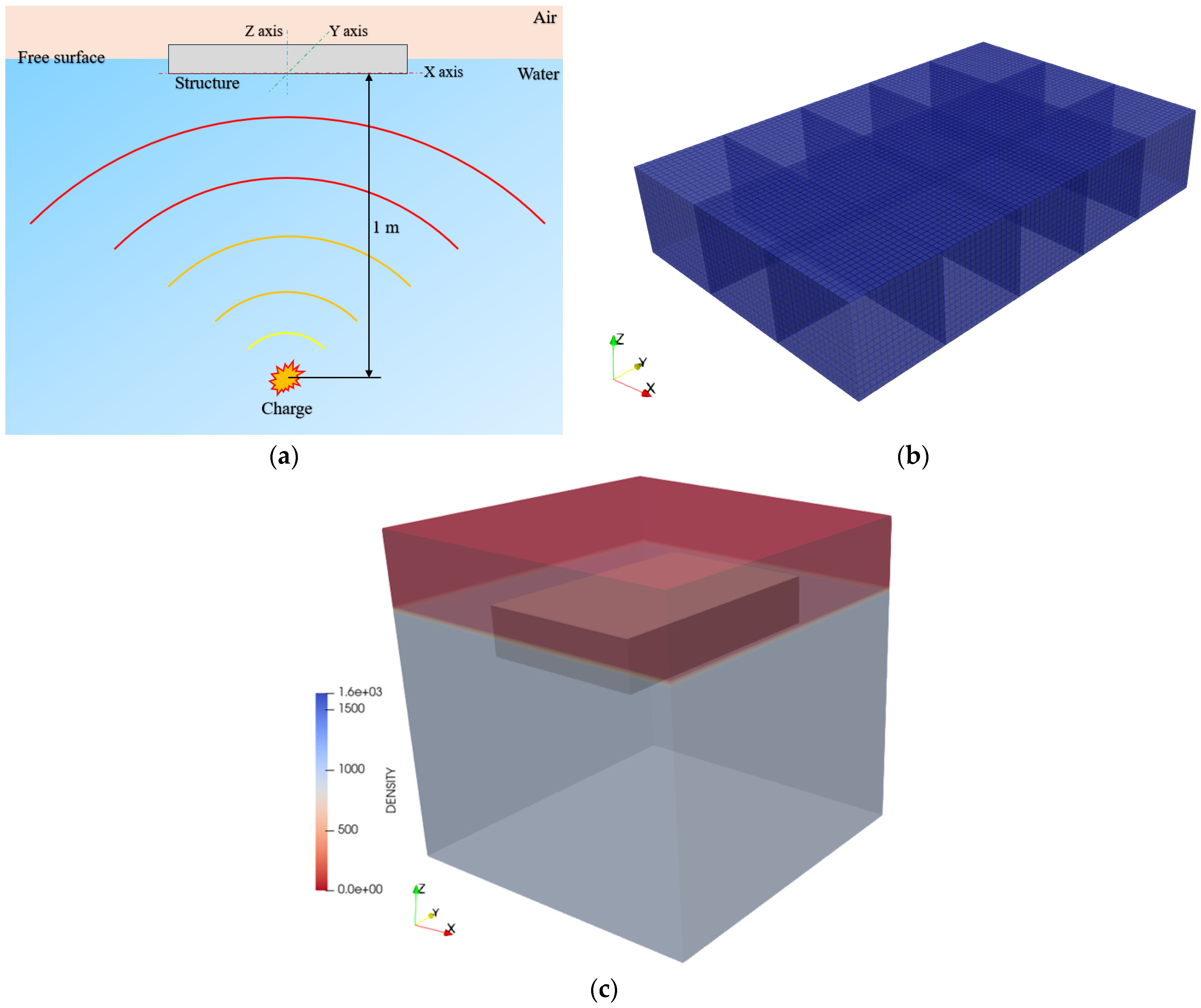
The UEL approach employs a two-step process: (i) evaluation of the pressure field due to UNDEX considering the structure as rigid; (ii) evaluation of the structural dynamic response subjected to the calculated pressure load while neglecting FSI effects [23].
In the first stage of the UEL method, the generation and propagation of the blast wave in the surrounding medium are simulated using the Eulerian mesh formulation. This step focuses on mapping the pressure load acting on the target structure and the implemented EOS are the same as for the CEL approach (Equations (1)–(4)).
The second stage of the UEL method involves using the pressure time history obtained in the first step as input for a pure Lagrangian analysis, considering the structure deformable.
An important aspect of UEL analysis for submerged and floating structures lies in the challenge of accounting for the added mass effect [29], caused by the mass of water in contact with the structure and not intrinsically considered as in the CEL approach.
In practical naval applications, three main strategies can be adopted to account for this effect, with increasing precision [29,30]: (i) increment the density of the considered material (most simple and rough method); (ii) employ numerical technique such as lumped masses connected to the wet surface with Multi-Point Constraint (MPC); (iii) explicitly model the volume of water around the structure (i.e., perform a CEL simulation to solve FSI but without the need to calculate the propagation of the shock wave). Added mass contribution should be considered within the 2° step of UEL strategy, where only the structure is present and subjected to the pressure field mapped in the 1°step onto the rigid target body.
To summarise, Figure 1 proposes a schematic representation and comparison between CEL and UEL approaches. Note that the UEL scheme of Figure 1b shows only the two main steps, although additional sub-steps (e.g., remapping techniques) may be used in practice to further reduce computational demands, as outlined above.

3. Case Study

In this section, the considered UNDEX scenario is illustrated and the numerical setup of the two approaches (CEL and UEL) is described with reference to the MSC Dytran software package (https://hexagon.com/products/dytran, accessed on 20 February 2025).

3.1. UNDEX Scenario

The scenario investigated in this work involves the detonation of a 0.18 kg submerged spherical TNT explosive charge at a 1 m stand-off distance from a floating double-bottom composite structure, as schematically shown in Figure 2a.
According to the classification of the UNDEX phenomenon in contact and non-contact, the proposed scenario belongs to the contact one [10], even if only the effects of the primary shock wave have been considered.
The examined composite double-bottom structure has dimensions of 1.75 m in length, 1.05 m in width, and 0.30 m in height (Figure 2b). The distance between the girders is 0.35 m, which is also the spacing between the floors. Based on Archimedes’ principle, the calculated draft T is 0.10 m. The thickness of the structural elements, consistent with those of naval structures, are reported in Table 1. The stiffeners have not been modelled for simplicity, but this does not compromise the validity of the approach, which is to demonstrate the differences between two different numerical approaches.
The structure under investigation features a typical naval arrangement, consisting of a grating of longitudinal and transversal beams enclosed at the top and bottom. Each structural element is made of composite plates composed of fiberglass and epoxy resin [31,32]. Each lamina is composed of a fiberglass weave and epoxy resin, which is widely used in applications like offshore wind turbines and the layup sequence is the same used in [32] (each mm has the sequence [0/45/-45/0]). The total weight of the structure is 148.9 kg, and the lamina properties are reported in Table 2.

3.2. Numerical Modelling

The Eulerian domain measures 2.0 m × 2.0 m × 2.0 m and encloses the Lagrangian structure subjected to UNDEX, as illustrated in Figure 2c. It consists of two main regions: a 1.35 m thick water layer and a 0.55 m thick air layer above the free surface. The air inside the double-bottom structure is excluded from the model for simplicity.
The Eulerian domain is discretized using a hexahedral mesh with a base element size of 15 mm, selected to accurately capture the peak pressure value in accordance with Cole’s formulation [10]. The Lagrangian domain, representing the double-bottom structure, is meshed with quadrilateral shell elements having a base size of 0.02 m, as shown in Figure 2b. This base size is selected following a mesh convergence process to ensure that the out-of-plane displacements of the structure’s plates have reached convergence.
The entire model is subjected to gravitational loading, and appropriate non-reflecting boundary conditions are applied to the Eulerian domain. The simulations are conducted over a total duration of 0.015 s to capture the maximum deformation of the structure. Hydrostatic pressure is initialized to correctly define the Eulerian domain conditions.
As previously mentioned, no boundary conditions were applied to the structural model, as the double-bottom composite structure is floating.
The implementation of the material characterizing the composite structural elements was carried out using the MAT2 entry in Dytran, implementing the parameters reported in Table 2.
As already introduced in Section 2.1, all the Eulerian materials considered inside the model (charge, water, and air) are modelled using a specific EOS and the parameters considered in the analysis are reported in Table 3.
For the UEL analyses, the first step follows the same setup as the CEL framework but assumes a rigid structure. In addition to imposing a rigid structure, the first step of the UEL is set according to the original philosophy of the decoupled analysis [23] by also constraining the structure (non-floating). This prevents not only deformation, but also rigid-body motion to exclude any FSI effects.
The second step of the UEL approach involves analyzing the dynamic structural response under the previously calculated pressure loads. This step uses the same structural mesh as described earlier and excludes the Eulerian domain.
Regarding the added mass contribution within UEL simulations, two strategies are implemented in this study:
  • Explicit modeling of added mass: in the second step, a numerical model is set up with water explicitly represented, performing a CEL simulation to account for FSI without solving the shock wave propagation.
  • Lumped mass approach [29,30]: in the second step, a numerical model is created with only the structure and a lumped mass applied to the wet surface using MPC. In this approach, the added mass is typically calculated as 150% of the ship’s displacement.
Since the second strategy provides results comparable to the first while being computationally faster, the presented results primarily correspond to this configuration. Additionally, cases without the added mass contribution in the UEL framework are also discussed.
The performed numerical analyses with the different constraining conditions and implemented approaches are summarized in Table 4.
Each analysis within Table 4 is performed in a workstation with 128 GB of RAM and an Intel® CoreTM i9-13900K 3.00 GHz CPU, considering 20 cores and the time required for each simulation is monitored.

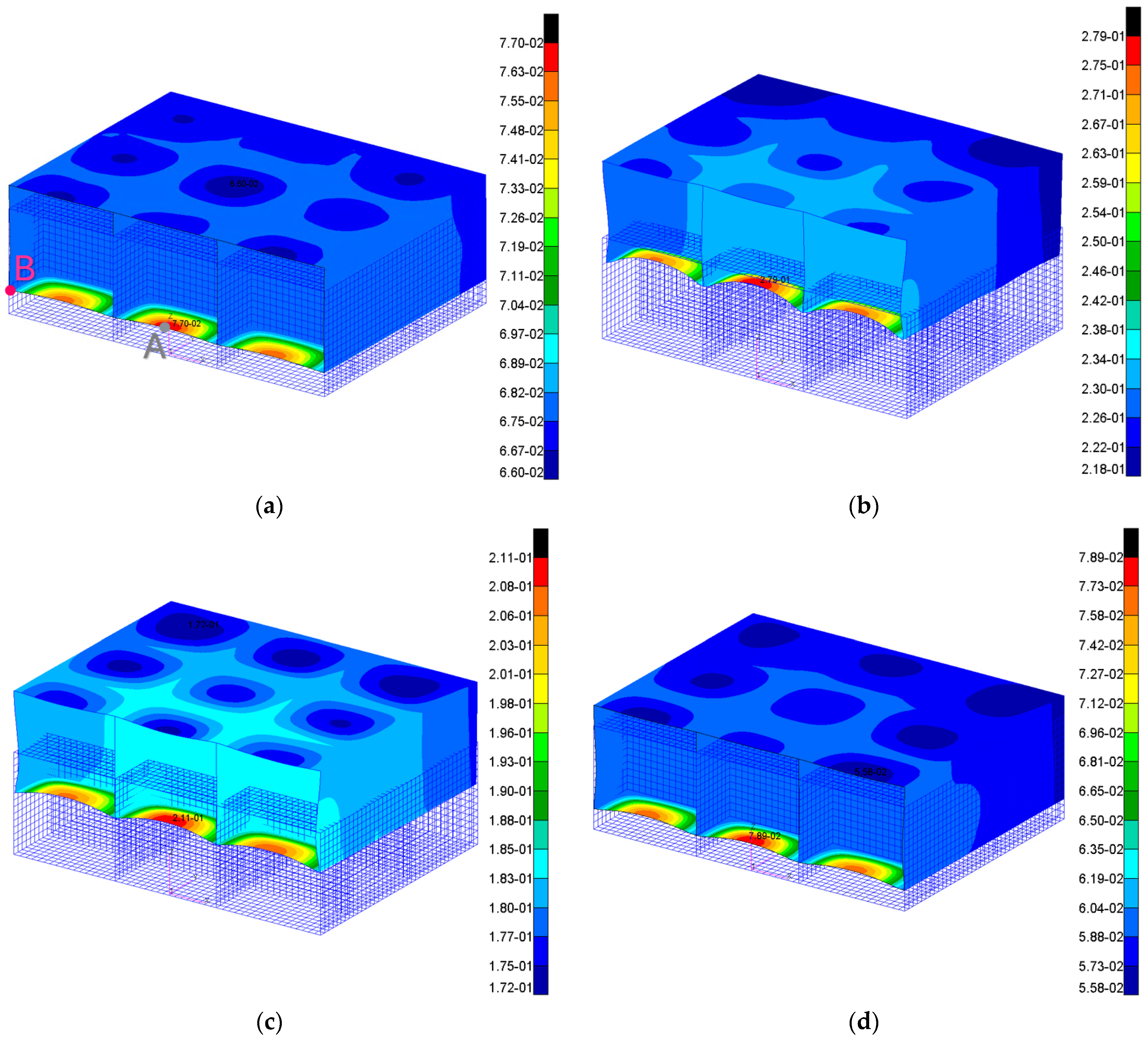
4. Results and Discussion

Figure 3 reports the evolution of the pressure field from the charge positions to the interaction with the structure for just the analysis n°1 of Table 4. Such results are useful to qualitatively evaluate their consistency with expectations: starting from the point of charge detonation, the primary shock front propagates spherically until it reaches the target structure and then the formation of the cavitation front affecting the area below the structure (Figure 3d) (common behaviour registered in these scenarios, particularly when plates are in contact with water on one side and air on the other).
To compare the results obtained from the different numerical analyses resumed in Table 4, the vertical displacement calculated in point A ( U Z , A , Figure 4a) at the final time step of the simulations (0.015 s) is chosen as reference. The displacement in point B ( U Z , B , Figure 4a) is registered to evaluate the rigid body motion (i.e., vertical translation due to shock pressure). The choice of point B is justified by the fact that the global curvature developed by the structure at the investigated instant is extremely small, as shown in Figure 5b. Specifically, the difference in vertical displacement between points C and B is negligible, making the use of point B as a reference for rigid body motion a valid and more practical alternative for comparisons.
The vertical displacement contour U Z plots for the cases of Table 4 are reported in Figure 4a–c. In this figure, a vertical section of the double-bottom structure positioned at its mid-length is considered for improved visualization. In Table 5, the recorded displacements in point A and B are reported; for point A, the difference between the effective vertical structural displacement and the rigid body motion is also calculated ( U Z , A U Z , B ).
The results presented in Figure 4a–c and Table 5 reveal that the UEL procedure imposes greater demands on the floating double-bottom from a structural perspective. In fact, the quantities U Z , A U Z , B for the UEL cases are approximately 400% and 190% higher than those from the CEL procedure without and with the added mass contribution, respectively.
Additionally, as expected, the primary shock wave from the UNDEX induces a rigid upward motion of the structure, accompanied by simultaneous deformations. These deformations manifest both globally, as an overall hogging curvature of the structure, and locally, as the plates between transverse and longitudinal stiffeners undergo significant deformation (see Figure 5b).
The discrepancy in deformations calculated using the CEL and UEL approaches can be attributed to the absence of FSI effects in the UEL framework. This FSI omission leads to an overestimated pressure profile during the first step of the UEL analysis, as shown in Figure 5a.
Considering Figure 5a, it is evident that the pressure trend in the UEL approach (black curve) is significantly higher than in the CEL approach (blue line). These findings align with observations from air-blast scenarios, where FSI effects mitigate and reduce the loads experienced by the structure [1,25]. In UNDEX scenarios, this behavior is even more pronounced due to additional phenomena such as cavitation, reflection, absorption and other FSI-related dynamics.
Furthermore, the inclusion of the added mass effect significantly enhances the agreement between the results from the uncoupled and coupled approaches.
Moving to the comparison of the time required for the analysis, the two-step uncoupled procedure is more advantageous than the coupled one, as shown in Table 5. Specifically, the CEL analysis involves a computational cost of about 46% higher than the UEL one (case two + three and two + four of Table 5). This time gap between CEL and UEL may widen significantly when the first step of the UEL is replaced with analytical formulas [27] from the literature capable of mapping the pressure induced by the UNDEX onto the naval structure’s surfaces.
Overall, the computational efficiency of the UEL approach with respect to CEL comes at the cost of producing results that are quite far from those obtained with coupled methods, demonstrating the necessity of correcting the uncoupled results to achieve the accuracy and reliability of the coupled ones.
For practical engineering applications, this discrepancy suggests that the uncoupled approach provides results significantly faster than coupled methods like CEL while being more conservative. This characteristic can be advantageous for rapid preliminary predictions, where a quick yet cautious estimation of structural response is required.
Finally, to test a simple approach for correcting UEL results, a calibration strategy is proposed here. In this context, the authors present an effective and straightforward method to correct UEL results by adjusting the well-known Hull Shock Factor ( H S F ) parameter [1,27] of the UNDEX event, thereby modifying the pressure profile and impulse acting on the hull. H S F parameter is used as an index of explosion severity concerning damage to the hull structure (external plating) and it is defined by Equation (6):
H S F = W T N T R  
where W T N T is the weight of the charge in kg of TNT equivalent and R the minimum distance in m from the center of the charge to the hull (standoff distance). The actual value of H S F for the considered UNDEX scenario is equal to 0.43.
From this point forward, the research introduces the terms Hull Shock Factor Coupled ( H S F C ) and Hull Shock Factor Uncoupled ( H S F U ), indicating the values of H S F for the coupled and uncoupled case, respectively, reminding that H S F C corresponds to the real one. To establish a robust procedure for correcting the UEL results, it was decided to adjust iteratively the actual value of the H S F to derive a modified value of H S F U that enables accurate results with the UEL approach. The best UEL results that match the coupled ones are obtained considering a H S F U equal to 0.23 and the 2°step UEL results are presented in Figure 4d, showing a high-level accuracy compared to Figure 4a.
To obtain a more general corrective approach for the grillage, the numerical analyses of Table 4 were repeated for two additional H S F C values, equal to 0.66 and 0.92. Then, the best value of H S F U are found to guarantee the best match between CEL and UEL.
The results obtained through this calibration procedure are presented in Figure 6, where the curve that fits the three points defines how the H S F U varies with respect to the H S F C .
This curve, valid for the specific case study only, obtained through the minimization of the root mean square error (RMSE) between the polynomial fit and the three points, should be interpreted as follows: if the real scenario has a H S F C equal to a certain value, to make use of the UEL framework, the corresponding H S F U must be applied. This approach allows taking advantage of the lower computational cost of uncoupled analyses while maintaining the accuracy of the CEL analysis.

5. Conclusions

This work addresses a topic that is not explicitly clear in the literature regarding underwater explosion phenomena, namely the role of the Uncoupled Eulerian–Lagrangian (UEL) approach in UNDEX investigations for composite ship-like structures. The UEL method can be adopted in UNDEX simulations to reduce computational costs with respect to traditional coupled approaches (like CEL, ALE, etc.), but it must be noted that they do not directly model FSI effects.
Two main goals have been achieved in this research. The first one is a rigorous comparison of UEL and CEL approaches considering a simple double-bottom fiber reinforced composite structure representative of a typical naval structure subjected to an UNDEX event. Specifically, the quantity of interest for the comparisons is represented by the vertical displacement at some representative points of the grillage. The second objective is to demonstrate a simple and effective method to calibrate uncoupled results to reach the accuracy of coupled ones, by leveraging a modification of the Hull Shock Factor parameter of the UNDEX event when simulating it in a UEL framework.
The results highlight the greater severity of the UEL approach with respect to the actual CEL prediction, which results in displacement values 190% higher than those obtained from the CEL analysis, considering the most accurate uncoupled model so the one with added mass contribution.
Despite this, to take advantage of the lower computational cost associated with UEL analyses, a correction of the obtained results is proposed to approximate those of the CEL analysis by leveraging the concept of the Hull Shock Factor. The calibration curve obtained links the real value of the Hull Shock Factor to the one that should be applied in the UEL analysis to achieve accurate and reliable results.
This research has potential industrial implications, as the faster UEL analyses could be employed as a rapid yet conservative prediction method for preliminary UNDEX assessments in naval engineering. By applying the proposed calibration approach, UEL simulations can provide efficient and reliable estimations while significantly reducing computational costs, making them a valuable tool for industrial applications where quick decision-making is required.
This work presents for the first time in literature a qualitative and quantitative comparison between CEL and UEL approaches for UNDEX phenomena on naval structures, highlighting the reduced computational cost of the UEL method but also its limited accuracy unless calibration procedures are introduced.

Author Contributions

J.B.: Conceptualization, Methodology, Validation, Formal Analysis, Investigation, Data curation, Writing—original draft preparation, Writing—review and editing, Visualization. G.K.O.D.: Conceptualization, Methodology, Validation, Formal Analysis, Investigation, Data curation, Writing—original draft preparation, Writing—review and editing. C.S.: Methodology, Resources, Writing—review and editing, Supervision. A.M.: Conceptualization, Methodology, Resources, Writing—review and editing, Supervision. All authors have read and agreed to the published version of the manuscript.

Funding

This study received no external funding.

Data Availability Statement

The data given in this article are the data supporting the results of this study and are available upon request.

Conflicts of Interest

The authors declare that they have no known competing financial interests or personal relationships that could have appeared to influence the work reported in this paper.

References

  1. Bardiani, J.; Lomazzi, L.; Sbarufatti, C.; Manes, A. A Machine Learning-based Tool to Correlate Coupled and Uncoupled Numerical Simulations for Submerged Plates Subjected to Underwater Explosions. J. Marine. Sci. Appl. 2025. [Google Scholar] [CrossRef]
  2. de Camargo, F.V. Survey on experimental and numerical approaches to model underwater explosions. J. Mar. Sci. Eng. 2019, 7, 15. [Google Scholar] [CrossRef]
  3. Tran, P.; Wu, C.; Saleh, M.; Bortolan Neto, L.; Nguyen-Xuan, H.; Ferreira, A.J.M. Composite structures subjected to underwater explosive loadings: A comprehensive review. Compos. Struct. 2021, 263, 113684. [Google Scholar] [CrossRef]
  4. Ming, F.R.; Zhang, A.M.; Xue, Y.Z.; Wang, S.P. Damage characteristics of ship structures subjected to shockwaves of underwater contact explosions. Ocean Eng. 2016, 117, 359–382. [Google Scholar] [CrossRef]
  5. Bardiani, J.; Sbarufatti, C.; Manes, A. Transfer Learning with Deep Neural Network Toward the Prediction of the Mass of the Charge in Underwater Explosion Events. J. Mar. Sci. Eng. 2025, 13, 190. [Google Scholar] [CrossRef]
  6. Qiankun, J.; Gangyi, D. A finite element analysis of ship sections subjected to underwater explosion. Int. J. Impact. Eng. 2011, 38, 558–566. [Google Scholar] [CrossRef]
  7. Rajendran, R.; Narasimhan, K. Deformation and fracture behaviour of plate specimens subjected to underwater explosion-a review. Int. J. Impact. Eng. 2006, 32, 1945–1963. [Google Scholar] [CrossRef]
  8. Ren, S.F.; Zhao, P.F.; Wang, S.P.; Liu, Y.Z. Damage prediction of stiffened plates subjected to underwater contact explosion using the machine learning-based method. Ocean Eng. 2022, 266, 112839. [Google Scholar] [CrossRef]
  9. Li, J.; Rong, J.L. Experimental and numerical investigation of the dynamic response of structures subjected to underwater explosion. Eur. J. Mech. B/Fluids 2012, 32, 59–69. [Google Scholar] [CrossRef]
  10. Cole, R.H.; Weller, R. Underwater Explosions. Phys. Today 1948, 1, 35. [Google Scholar] [CrossRef]
  11. Wang, H.; Cheng, Y.S.; Liu, J.; Gan, L. The Fluid-Solid Interaction Dynamics between Underwater Explosion Bubble and Corrugated Sandwich Plate. Shock. Vib. 2016, 2016, 6057437. [Google Scholar] [CrossRef]
  12. Kong, X.S.; Gao, H.; Jin, Z.; Zheng, C.; Wang, Y. Predictions of the responses of stiffened plates subjected to underwater explosion based on machine learning. Ocean Eng. 2023, 283, 115216. [Google Scholar] [CrossRef]
  13. Löhner, R.; Li, L.; Soto, O.A.; Baum, J.D. An arbitrary Lagrangian–Eulerian method for fluid–structure interactions due to underwater explosions. Int. J. Numer. Methods Heat Fluid Flow 2023, 33, 2308–2349. [Google Scholar] [CrossRef]
  14. Sagar, H.J.; El Moctar, O. Dynamics of a cavitation bubble between oblique plates. Phys. Fluids 2023, 35, 013324. [Google Scholar] [CrossRef]
  15. Sigrist, J.F.; Broc, D. A versatile method to calculate the response of equipment mounted on ship hulls subjected to underwater shock waves. Finite Elem. Anal. Des. 2023, 218, 103917. [Google Scholar] [CrossRef]
  16. Walters, A.P.; Didoszak, J.M.; Kwon, Y.W. Explicit modeling of solid ocean floor in shallow underwater explosions. Shock. Vib. 2013, 20, 189–197. [Google Scholar] [CrossRef]
  17. Huang, H.; Jiao, Q.J.; Nie, J.X.; Qin, J.F. Numerical modeling of underwater explosion by one-dimensional ANSYS-AUTODYN. J. Energetic Mater. 2011, 29, 292–325. [Google Scholar] [CrossRef]
  18. Ding, P.; Buijk, A. Simulation of under water explosion using MSC Dytran. Ann. Arbor. 2006, 1001, 48105. [Google Scholar]
  19. Wang, Q. Multi-oscillations of a bubble in a compressible liquid near a rigid boundary. J. Fluid Mech. 2014, 745, 509–536. [Google Scholar] [CrossRef]
  20. Wang, Y.; Dong, H.; Dong, T.; Xu, X. Dumbbell-Shaped Damage Effect of Closed Cylindrical Shell Subjected to Far-Field Side-On Underwater Explosion Shock Wave. J. Mar. Sci. Eng. 2022, 10, 1874. [Google Scholar] [CrossRef]
  21. DeRuntz, J.A.; Geers, T.L.; Felippa, C.A. The Underwater Shock Analysis Code (USA-Version 3): A Reference Manual; Defense Nuclear Agency: Washington, DC, USA, 1980.
  22. Qiu, G.; Henke, S.; Grabe, J. Application of a Coupled Eulerian-Lagrangian approach on geomechanical problems involving large deformations. Comput. Geotech. 2011, 38, 30–39. [Google Scholar] [CrossRef]
  23. Giuliano, D.; Lomazzi, L.; Giglio, M.; Manes, A. On Eulerian-Lagrangian methods to investigate the blast response of composite plates. Int. J. Impact. Eng. 2023, 173, 104469. [Google Scholar] [CrossRef]
  24. Kumar, L.; Tummalapalli, S.; Rathi, S.C.; Murthy, L.B.; Krishna, A.; Misra, S. Machine learning with word embedding for detecting web-services anti-patterns. J. Comput. Lang. 2023, 75, 101207. [Google Scholar] [CrossRef]
  25. Lomazzi, L.; Morin, D.; Cadini, F.; Manes, A.; Aune, V. Deep learning-based analysis to identify fluid-structure interaction effects during the response of blast-loaded plates. Int. J. Prot. Struct. 2023, 15, 722–752. [Google Scholar] [CrossRef]
  26. The MacNeal-Schwendler Corporation (MSC). DYTRAN User Manual. 2023. Available online: https://www.manuallib.com/file/2615765 (accessed on 20 February 2025).
  27. Bardiani, J.; Kyaw Oo D’Amore, G.; Sbarufatti, C.; Manes, A. Machine Learning Combined with Numerical Simulations: An Effective Way to Reconstruct the Detonation Point of Contact Underwater Explosions with Seabed Reflection. J. Mar. Sci. Eng. 2025, 13, 526. [Google Scholar] [CrossRef]
  28. Bardiani, J.; Giglio, M.; Sbarufatti, C.; Manes, A. On the Exploration of the Influence of Seabed Reflected Waves on Naval Structures. Eng. Proc. 2025, 85, 7. [Google Scholar] [CrossRef]
  29. Nestegård, A.; Ronæss, M.; Hagen, Ø.; Ronold, K.; Bitner-Gregersen, E.M. New DNV Recommended Practice DNV-RP-C205 on Environmental Conditions and Environmental Loads. In Proceedings of the Sixteenth International Offshore and Polar Engineering Conference, San Francisco, CA, USA, 28 May 2006. [Google Scholar]
  30. ShipRight Design and Construction Structural Design Assessment Procedure for Primary Structure of Passenger Ships Working Together for a Safer World. 2017. Available online: https://www.academia.edu/14512983/Structural_Design_Assessment_Primary_Structure_of_Passenger_Ships_Guidance_on_direct_calculations (accessed on 20 February 2025).
  31. Singh, K.K.; Singh, N.K.; Jha, R. Analysis of symmetric and asymmetric glass fiber reinforced plastic laminates subjected to low-velocity impact. J. Compos. Mater. 2016, 50, 1853–1863. [Google Scholar] [CrossRef]
  32. Poloni, D.; Oboe, D.; Sbarufatti, C.; Giglio, M. Variable Thickness Strain Pre-Extrapolation for the Inverse Finite Element Method. Sensors 2023, 23, 1733. [Google Scholar] [CrossRef]
Figure 1. (a) CEL analysis scheme applied to the section of a submarine considering the detonation of the explosive, the wave propagation and FSI. (b) UEL scheme applied to the same structure: a Eulerian simulation considers detonation of the explosive and wave propagation. The pressure is mapped and consequently applied to the structure in a Lagrangian simulation.
Jcs 09 00177 g001
Figure 2. Features of the scenario considered: (a) relative position between structure and charge, (b) 3-D view of the grillage with 60% opacity to visualize the internal structural arrangement and (c) density pattern (kg/m3) for the 3D numerical model with the structure inside the Eulerian domain (charge not visible).
Jcs 09 00177 g002
Figure 3. Pressure field at different instants for the 3D coupled model (in Pa): (a) t = 10−8 s, (b) t = 0.0003 s, (c) t = 0.0007 s and (d) t = 0.0009 s. Legend scale adjusted for better shock front visualization.
Jcs 09 00177 g003
Figure 4. Magnitude displacement Uz plot contours (in m): (a) CEL–Floating and deformable structure, (b) UEL 2°step without added mass contribution, (c) UEL 2°step considering added mass contribution and (d) UEL 2°step considering added mass contribution and correction strategy. Same reference system of Figure 2b.
Jcs 09 00177 g004
Figure 5. (a) Comparison between the overpressure vs. time registered at the central mesh element of the outer bottom of the grillage in cases one and two of Table 4 for the time window 0–0.002 s. (b) Indication of the different motions and deformations of the grillage in the CEL case (displacements contour in (m) with a magnification factor of 10 to better visualize the motion’s components).
Jcs 09 00177 g005
Figure 6. H S F U vs. H S F C curve that defines the passage from UEL results to CEL ones for the grillage.
Jcs 09 00177 g006
Table 1. Thicknesses of all double-bottom’s structural elements.
Structural ElementTypeThickness [mm]
Outer bottomPlate15
Inner bottomPlate12
GirderPlate10
FloorPlate10
Table 2. Fiberglass-epoxy lamina material properties [32].
E 11 [MPa] E 22 [MPa] υ 12 [MPa] G 12 [MPa] G 13 [MPa] G 23 [MPa]Thickness [mm]
26,00026,0000.13800280028000.25
Table 3. Lagrangian (double-bottom composite structure) and Eulerian (water, air and charge) material properties used to assess the numerical model.
MaterialMSC Dytran ModelInput Parameters
Fiber-reinforced compositeMAT2 (Anisotropic material)See Table 2
WaterPolynomial EOS ρ = 1025   k g / m 3 ,   K = 2.2 · 10 9   P a ,
e = 83950   J / k g ,   a 1 = 2.314 · 10 9   P a ,
a 2 = 6.561 · 10 9   P a ,   a 3 = 1.126 · 10 9   P a ,
b 0 = 0.4934   - ,   b 1 = 1.3937   - ,   b 2 = 0.00   -
Charge (TNT)JWL EOS ρ = 1630   k g / m 3 ,   W = 1.47   k g ,
e = 4.76 · 10 6   k J / k g ,   A = 3.7 · 10 11   - ,
B = 2.23 · 10 9   - ,   R 1 = 4.15   - ,
R 2 = 0.95   - ,   ω = 0.3   -
Air above the free surfaceIdeal gas EOS ρ = 1.225   k g / m 3 ,   γ = 1.4   - ,
e = 2.14 · 10 5   J / k g ,   R = 287   J / k g · K
Table 4. List of the numerical analyses performed with MSC Dytran suite.
Type
1CEL–Floating and deformable structure
2UEL 1°step–Rigid and fixed structure
3UEL 2°step–Deformable structure–No added mass contribution
4UEL 2°step–Deformable structure–Considered added mass contribution
Table 5. Comparison between the results of the analysis of Table 4 based on the vertical displacements recorded at representative points and computational time. Point A and B are depicted in Figure 4a.
TypeTime U Z , A
[m]
U Z , B
[m]
U Z , A U Z , B
[m]
1CEL–Floating and deformable grillage1 h 31 min0.0770.0670.010
2UEL 1°step–Rigid and fixed grillage1 h 01 min---
3UEL 2°step–Deformable grillage–No added mass contribution1 min0.2790.2290.050
4UEL 2°step–Deformable grillage–Considered added mass contribution2 min0.2110.1820.029
Disclaimer/Publisher’s Note: The statements, opinions and data contained in all publications are solely those of the individual author(s) and contributor(s) and not of MDPI and/or the editor(s). MDPI and/or the editor(s) disclaim responsibility for any injury to people or property resulting from any ideas, methods, instructions or products referred to in the content.

