Article

A Study on the Charging–Discharging Mechanism of All Solid-State Aluminum–Carbon Composite Secondary Batteries

Department of Materials Science and Engineering, National Cheng Kung University, Tainan 701, Taiwan
*
Author to whom correspondence should be addressed.
J. Compos. Sci. 2025, 9(4), 166; https://doi.org/10.3390/jcs9040166
Submission received: 5 March 2025 / Revised: 21 March 2025 / Accepted: 25 March 2025 / Published: 29 March 2025
(This article belongs to the Special Issue Feature Papers in Journal of Composites Science in 2025)

Abstract

:
Aluminum solid-state batteries are emerging as one of the most promising energy storage systems, offering advantages such as low cost and high safety. This study adopts a safe and cost-effective approach by alloying and doping the all-solid-state aluminum-ion battery to enhance its electrochemical performance. This research further explores the electrochemical impacts of these modifications on the performance of solid-state aluminum batteries. In this experiment, aluminum-based anodes were deposited onto nickel foil using the thermal evaporation (TE) method. At the same time, the graphite film (GF) cathode material was enriched with sodium (GFN) through a solution-based process. The system was combined with magnesium silicate solid electrolytes to investigate the all-solid-state aluminum-carbon battery′s structural characteristics and charge–discharge mechanisms. The experimental results demonstrate that the aluminum-coated electrode alloying effects and the graphite film modification significantly improve battery performance. The system achieved a maximum specific capacity of approximately 700 mAh g−1, with a cycle life exceeding 100 cycles. Furthermore, the microstructural characteristics and phase structure of the aluminum evaporation film were confirmed. Analysis of ion transport pathways during the charge–discharge cycles of the all-solid-state aluminum-carbon battery revealed that both aluminum and magnesium ions play critical roles in the electrode processes.

1. Introduction

With the rapid growth of portable electronic devices and electric vehicles (EVs), the demand for low-cost, high-safety energy storage systems continues to rise. The liquid lithium-ion battery is the most widely commercialized energy storage system, known for its high energy density, low self-discharge rate, and lack of memory effect, making it a focal point of research and development in recent years [1,2]. However, lithium-ion batteries still face several significant challenges. First, the limited availability of lithium resources in the Earth’s crust leads to higher costs and potential resource shortages. Second, safety concerns persist, as misuse of lithium-ion batteries can result in swelling, dendrite penetration of the separator, and risks of leakage, fire, or even explosion [3,4]. Third, proper disposal of lithium-ion batteries is critical, as they contain hazardous materials such as carcinogenic cobalt (Co), and their organic liquid electrolytes pose risks to human health and the environment [5]. Therefore, considering these challenges, developing alternative battery systems to replace lithium-ion technology is crucial.
Aluminum-ion batteries, as energy storage systems, offer several advantages, including a high theoretical volumetric capacity (8046 mAh cm−3), excellent stability, abundant resources, and low cost, positioning them as one of the most promising alternatives [6,7]. However, aluminum undergoes significant volume changes during charge–discharge cycles, which can lead to pulverization and detachment from the electrode, thereby reducing cycling performance [8]. Moreover, aluminum reacts rapidly and irreversibly with oxygen, forming a dense oxide layer on its surface that lowers battery potential and delays anode activation [9,10]. To mitigate these issues, the addition of alloying elements has been shown to enhance the performance of aluminum batteries. Recent studies have demonstrated that doping elements such as Mg, Cu, Sn, Zn, and Ni can significantly improve the electrical properties of aluminum-ion batteries [11,12,13,14]. Among these, magnesium has the unique ability to dissolve into the aluminum matrix, stabilizing the lattice and enhancing the mechanical properties of the aluminum base. Research indicates that adding an appropriate amount of magnesium (<5 wt. %) to aluminum can lower the self-corrosion rate of the aluminum anode and activate the passivation layer, thereby improving its electrochemical performance. The presence of magnesium ions can also increase capacity [15,16,17]. Research has also shown that incorporating silicon into aluminum–graphite composite electrodes can increase capacity by 50%, improving capacity retention and coulombic efficiency [18]. Additionally, studies report that the minor addition of nickel to the aluminum matrix can form the intermetallic compound (IMC) Al3Ni, enhancing high-temperature and corrosion resistance [19]. Furthermore, aluminum–nickel IMCs effectively mitigate stress from volume changes, preserving electrode structural integrity and improving cycling stability [11]. Consequently, investigating the electrode characteristics of aluminum–silicon and aluminum–magnesium cathodes on nickel foil holds significant potential for practical applications.
To ensure uniformity and optimal thickness of the electrode composition, this study utilized aluminum-based electrodes deposited onto nickel foil via thermal evaporation, followed by a heat treatment process. This process promoted solid-state diffusion reactions between the aluminum electrode and nickel foil, forming small amounts of aluminum–nickel IMCs at the interface [11]. Additionally, to prevent battery leakage and enhance energy density, sodium-based magnesium silicate was used as the electrolyte [20,21], alongside a high-conductivity graphite film as the cathode [22,23] and aluminum-coated nickel foil as the anode, forming an all-solid-state aluminum-ion battery. This study systematically examines the thermally evaporated electrodes, analyzing the capacity of aluminum–silicon and aluminum–magnesium alloy electrodes and the passivation layer activity and structural properties.
In conclusion, this study employed the thermal evaporation (TE) method [24] to fabricate aluminum alloy/nickel anodes, followed by heat treatment. In the graphite cathode, phosphate modification (sodium-enriched treatment) was applied, and sodium ions were expected to increase capacity [22]. Sodium-based magnesium silicate was used as the electrolyte to assemble an all-solid-state aluminum-ion battery. This study systematically examined the impact of alloying on battery performance, establishing ion transport pathways and mechanisms during charge–discharge processes. These findings provide valuable insights for potential applications in the energy storage industry.

2. Experimental Procedure

2.1. Fabrication of Electrodes

This study used graphite film (GF) as the cathode, which was sodium-enriched through a solution method by soaking it in a saturated sodium phosphate solution [22]. First, the carbon material was thermally compressed onto a polyimide film. After compressing it into a sheet, the polyimide film was peeled off, forming GF (no extra binder, purity > 99.8%, thickness: 0.2–0.3 mm). The GF was soaked in the sodium phosphate solution for 1 h and then dried in an oven at 55 °C, after which it was designated as GFN. For the electrolyte, 0.27 g of sodium-based magnesium silicate powder (Mg2Si3O8·5H2O, purity > 99.0%, particle size: 1–10 µm) was placed in a 13 mm diameter pellet mold. Using a uniaxial pressing machine, 140 kg/cm2 of pressure was applied for 10 s, forming a circular pellet approximately 1 mm thick and 13 mm in diameter, referred to as Ingot B. The TE aluminum alloy anode was prepared using a thermal evaporator. Pure Al (Al), Al-5Mg (AM), and Al-10Si-1Mg (ASM) powders were thermally evaporated onto the surface of a pure nickel substrate to form an aluminum alloy coating. Therefore, sodium and magnesium ions were expected to be involved in the reaction. The process involved reducing the chamber pressure to below 10−5 torr, followed by passing a current of 60 A to heat the platform for 5 min, melting and evaporating the aluminum alloy powder. The vapor was deposited onto the nickel substrate, forming a uniform aluminum alloy coating. The evaporation process was repeated twice to ensure sufficient thickness, resulting in complete substrate coverage. The anodes were named TE Al/Ni, TE AM/Ni, and TE ASM/Ni, respectively, based on the powder used.

2.2. Characterization Analysis of Materials

The phase structures of the cathode and anode were analyzed using a 2D X-ray diffractometer (Bruker D8 Discover with GADDS, Bruker AXS Gmbh, Karlsruhe, Germany). Surface morphology and semi-quantitative elemental analysis of the electrodes were performed using a multifunction field emission scanning electron microscope (HR-SEM, HITACHI SU8000, Tokyo, Japan) equipped with EDAX and electron backscatter diffraction capabilities (EBSD, HITACHI SU-5000, Tokyo, Japan). The differences in cathode bonding before and after modification (immersed in a saturated sodium phosphate solution for 10 min) were examined using Fourier transform infrared spectrometry (FTIR, PerkinElmer Spectrum Two, PerkinElmer, Waltham, MA, USA), with a vibration frequency range set from 500 to 4000 cm−1. Electrode resistivity was measured using a planar light source resistance measurement module (MCP-T610, Mitsubishi, Hirasuka, Japan). To investigate the diffusion behavior and elemental distribution at the interface of the thermally deposited aluminum alloy anodes, cross-sectional microstructural characteristics were analyzed using an electron probe microanalyzer (EPMA, JEOL JXA-8900R, JEOL, Tokyo, Japan).

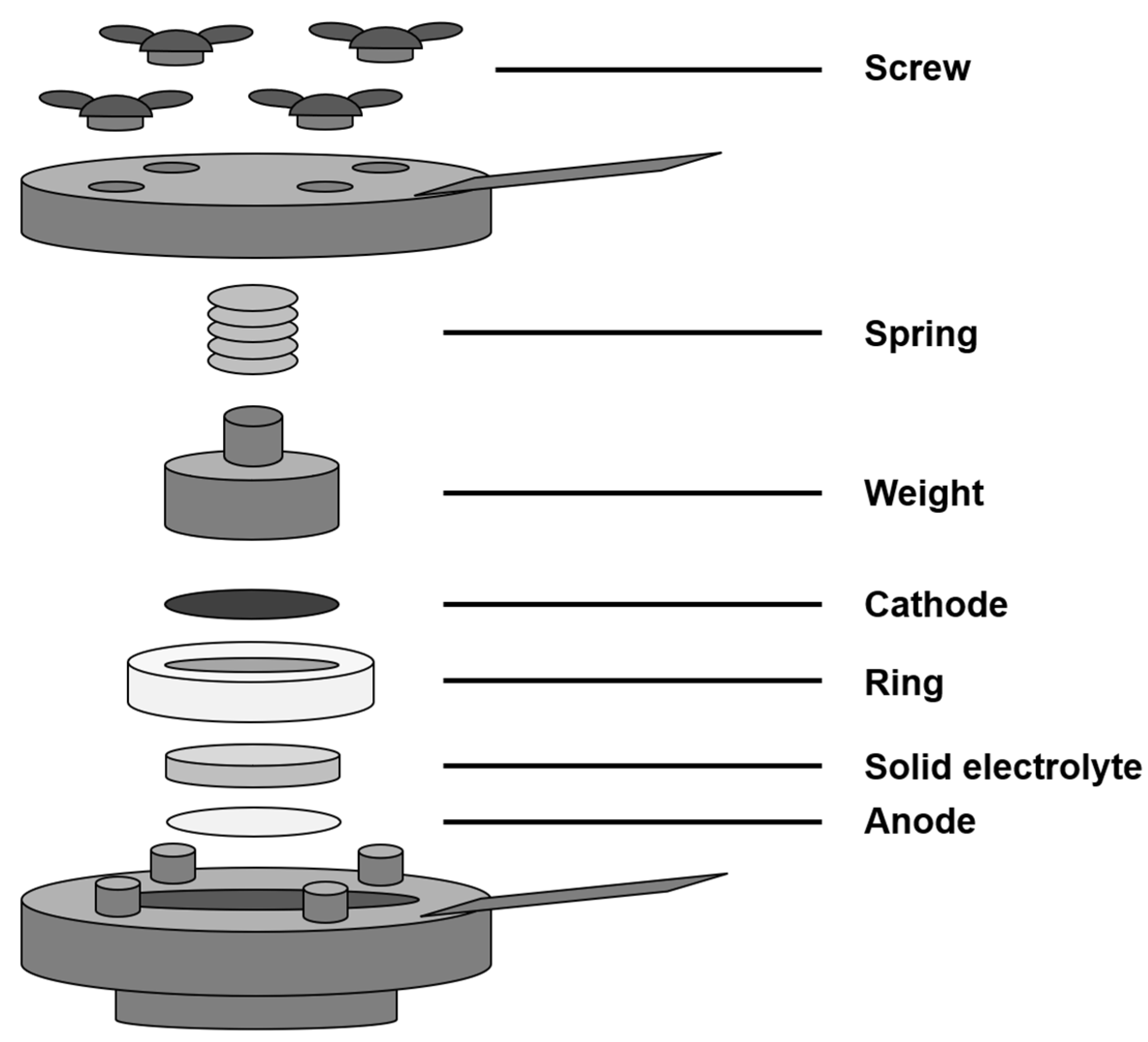
2.3. BT Cell Charge and Discharge Test

To investigate the capacitance and cyclic stability, the cathode, solid electrolyte, and anode were assembled into a sandwich structure, as shown in Figure 1, and integrated into a button-type battery (BT cell) [25]. The setup consisted of a fixed insulating plastic ring, a weight, and a spring and was secured with screws to form the BT cell, as illustrated in Figure 2.
In the experiment, a constant voltage of 12 V was applied for charging over 10 min, while the discharge rate was set to 0.05 mA. Discharge continued until the battery was depleted entirely, which was defined as one cycle. Fifty testing cycles were conducted to assess the specific capacity performance of the various thermally deposited aluminum alloy anodes.

3. Results and Discussion

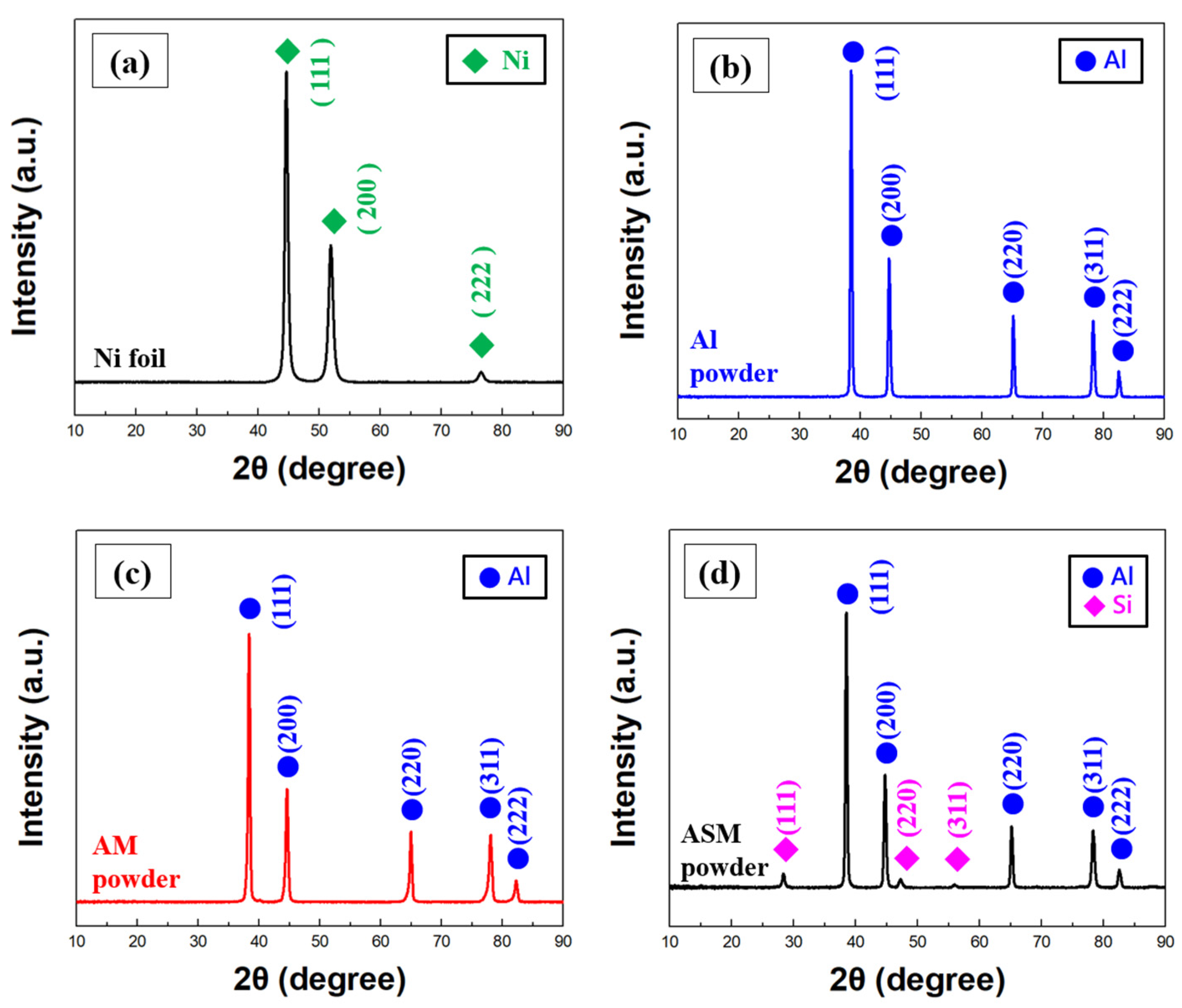
3.1. Analysis of Cathode Modification Characteristics

First, the surface morphology of the graphite electrodes was analyzed before and after sodium-rich modification. Figure 3a shows the original surface features of GF, which exhibits irregular cracks resulting from the thermal pressing process [25]. In contrast, Figure 3b displays the surface characteristics of GFN after treatment, revealing numerous irregular deposits. An EDAX analysis at a magnified scale (Figure 3c) provided the data shown in Table 1, indicating the presence of P, O, and Na signals from the sodium phosphate solution in GFN compared to GF. According to the X-ray diffraction (XRD) analysis (Figure 4), no significant phase changes were observed in the graphite electrodes before and after modification, suggesting that the surface deposits on the modified electrodes possess poor crystallinity and uneven distribution. FTIR analysis was conducted to examine the bonding characteristics of the electrodes, as illustrated in Figure 5. Compared to GF, GFN exhibited additional peaks at wave numbers 553, 995, 1662, and 3027 cm−1, corresponding to P-O, P-O, C=C, and O-H signals, respectively [26]. The resistivity of the electrodes was measured using a four-point probe instrument, as summarized in Table 2, revealing no significant differences between the two electrodes. This indicates that GFN retains good conductivity after modification with sodium phosphate. Overall, the analysis confirms that the surface deposits on GFN consist of sodium phosphate.
The experiment was conducted using a nickel anode (without a coating layer) and Ingot B to form the BT cell, allowing for a comparison of the specific capacity performance between GF and GFN, as shown in Figure 6. The maximum specific capacity increased from 14 mAh g−1 to 51 mAh g−1, with an increase of seven cycles in the overall performance. This improvement can be attributed primarily to the stability of the P-O covalent bonds, which help maintain the structural integrity of the cathode during charge and discharge cycles, facilitating more stable and effective ion intercalation and de-intercalation within the layered structure of the cathode [22]. Additionally, the presence of sodium in GFN enhances the charge and discharge reactions, thereby improving the overall electrochemical activity of the all-solid-state battery. These findings demonstrate that soaking in a saturated sodium phosphate solution is an effective, safe, and low-cost method for cathode modification.

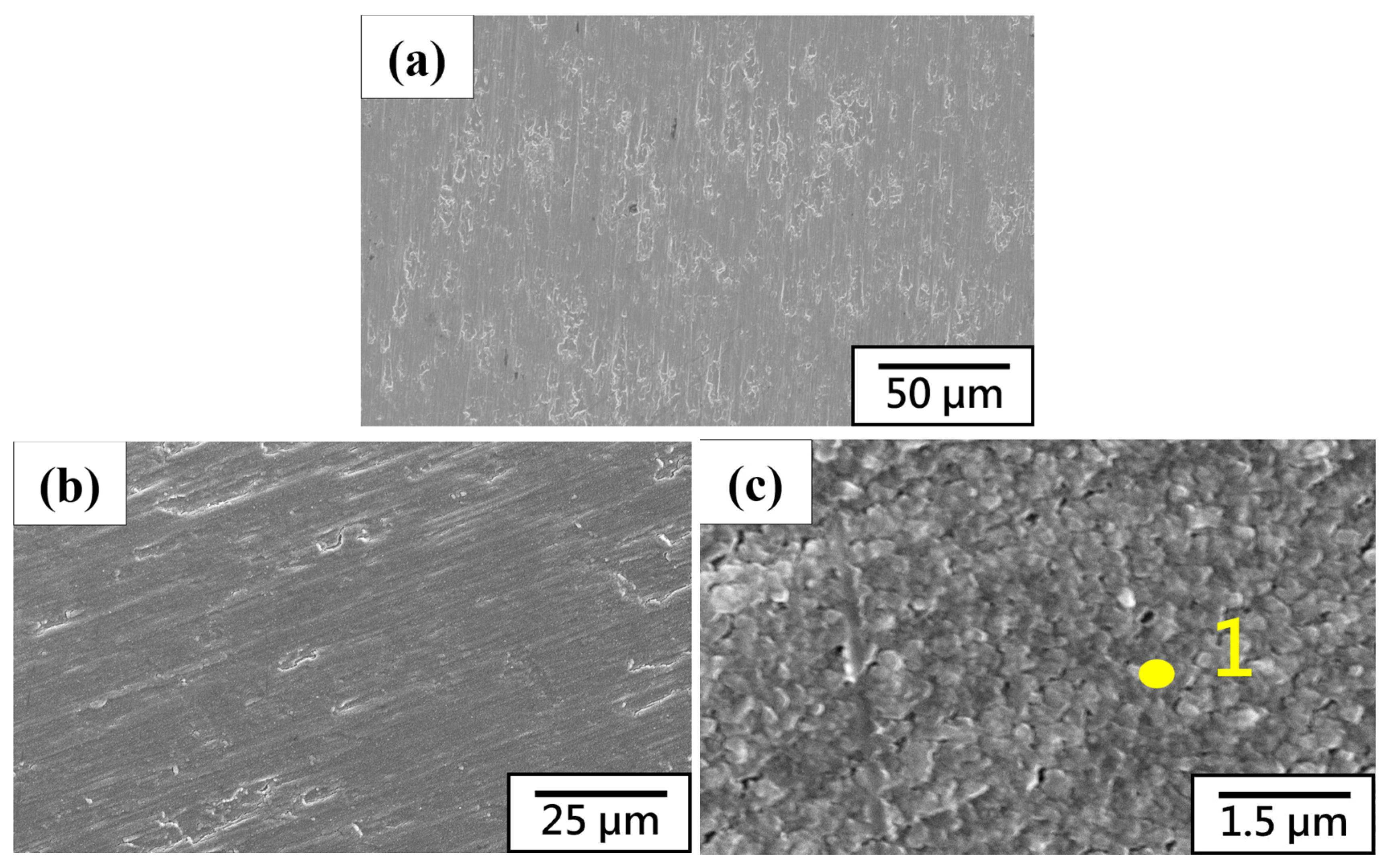
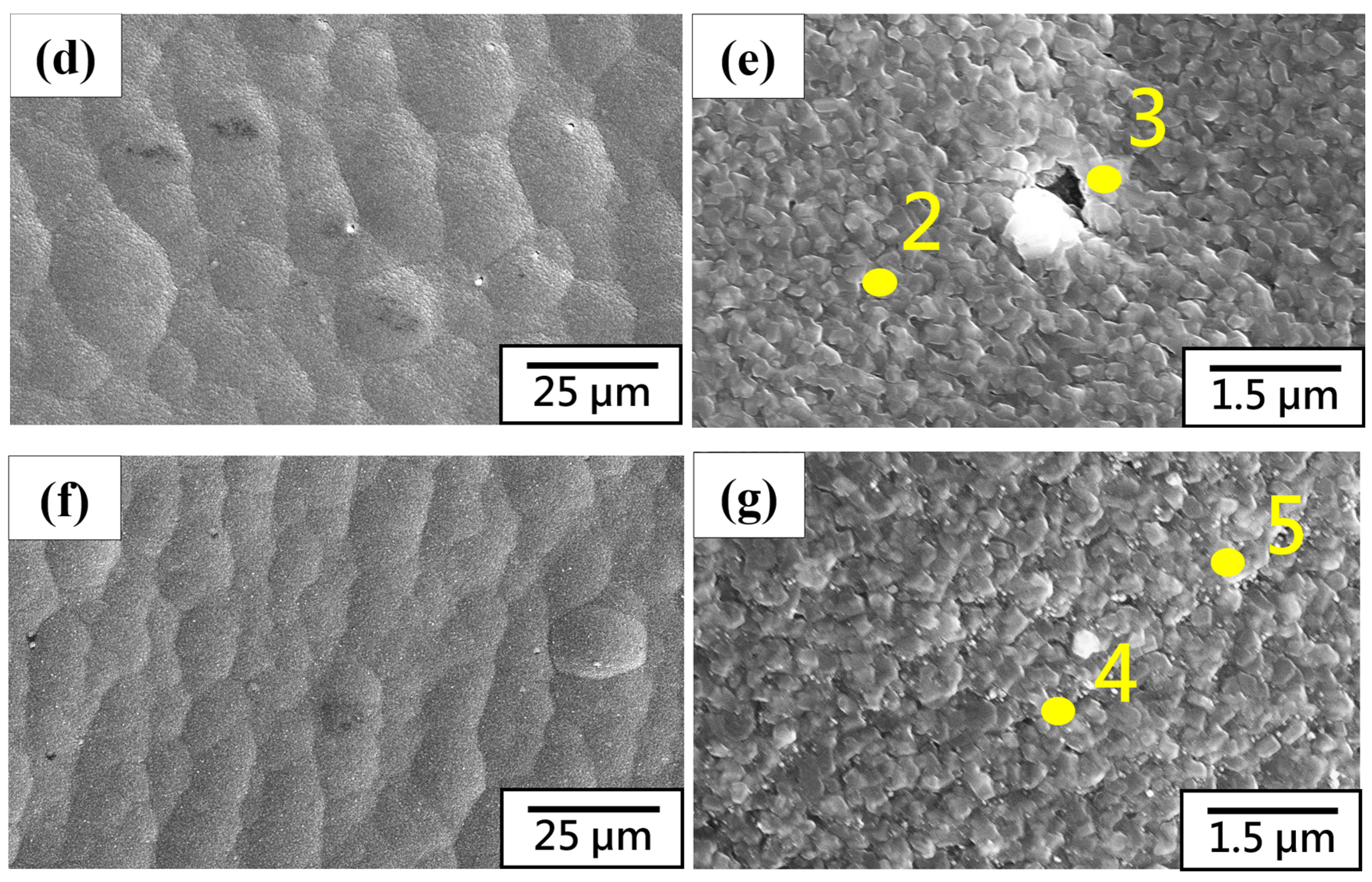
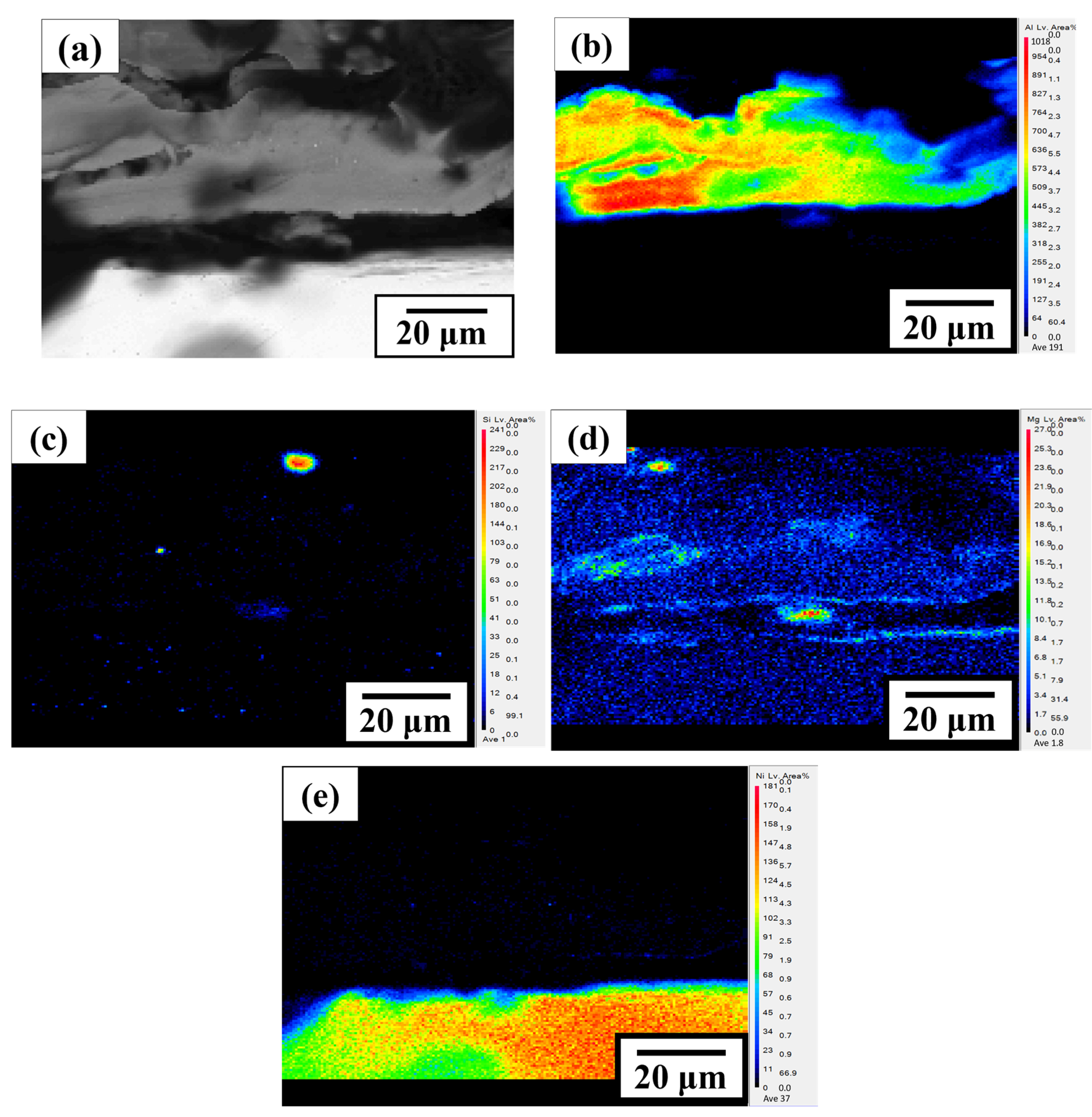
3.2. Microstructure Characteristics and Electrochemical Analysis of Thermal Evaporation Anode

First, XRD analysis was performed on the nickel substrate and three types of aluminum alloy powders, as illustrated in Figure 7. As shown in Figure 7c,d, no significant magnesium signal peaks were observed. According to the aluminum–magnesium phase diagram [27], this absence indicates that magnesium exists in a solid solution within the aluminum matrix. Additionally, surface SEM analysis was conducted on the thermally deposited aluminum alloy electrodes, as shown in Figure 8. Figure 8b–g reveal a uniform and complete surface coating. EDAX analysis was performed at the numbered locations in Figure 8, with the results presented in Table 3 indicating that the TE ASM/Ni samples did not exhibit detectable silicon signals. Concurrent XRD analysis was also conducted, as shown in Figure 9, where Al3Mg2 was detected in the TE AM/Ni samples. No silicon signal was found in the TE ASM/Ni samples for two reasons: (1) During the deposition process, the melting of the powder leads to phase separation between magnesium and silicon, causing silicon to revert to its atomic state. Consequently, the thermal deposition process is unable to effectively evaporate the high-melting-point silicon atoms, resulting in their absence in the coating. (2) The silicon content may fall below the detection limit of the analytical instrument, leading to significant differences in the composition of the aluminum alloy coatings for TE AM/Ni and TE ASM/Ni compared to the original Al-5Mg and Al-10Si-1Mg powders.
To investigate the presence of Al-Ni IMCs in the thermally deposited electrode samples and to measure the thickness of the aluminum alloy coating, EPMA analysis was conducted on the TE ASM/Ni sample, which exhibited the best cycle life, as shown in Figure 10. The coating thickness was found to be approximately 27 µm. Integrating the XRD analysis (Figure 7) confirms that some magnesium is solid-solubilized within the aluminum coating, and there is no evidence of diffusion between the deposited aluminum alloy layer and the nickel foil, indicating that no Al-Ni IMCs were formed at the interface [11]. This absence can be attributed to two factors: (1) The thermal deposition process is relatively short, preventing the reduction and decomposition of the passivation layer on the nickel substrate, which hinders diffusion between the two materials and inhibits the formation of Al-Ni IMCs. (2) The total amount of generated Al-Ni IMCs may be below the detection limit of the analytical instrument.
Charge–discharge cycling tests were conducted on TE Al/Ni, TE AM/Ni, and TE ASM/Ni, as illustrated in Figure 11. The maximum specific capacities for the three samples were 251, 239, and 293 mAh g−1, respectively, with TE ASM/Ni demonstrating the best maximum specific capacity and cycle life, while TE AM/Ni exhibited the poorest performance. According to the literature [17], when magnesium exists in solid solution form within aluminum, it can activate the surface passivation layer and enhance electrochemical activity, thereby improving the electrode’s application characteristics. However, when the magnesium content exceeds a certain threshold, Al3Mg2 IMCs form, which can exacerbate anode self-corrosion and increase the battery’s internal resistance due to the presence of aluminum–magnesium IMCs. Consequently, the specific capacity performance of aluminum–magnesium alloy electrodes is suboptimal.
To support this discussion, the resistivities of the three samples were compared using a four-point probe, as shown in Table 2. TE AM/Ni exhibited the lowest conductivity due to the formation of Al3Mg2 IMCs, which increase internal resistance, while TE ASM/Ni demonstrated the best conductivity. It is noteworthy that, theoretically, solid-solubilized magnesium would be expected to increase resistivity; however, the resistivity of TE ASM/Ni significantly decreased compared to TE Al/Ni. This confirms that adding a small amount of magnesium (below the solubility limit) to the aluminum matrix can activate the surface passivation layer and enhance overall electrochemical characteristics, highlighting the beneficial effect of alloying in all-solid-state aluminum-ion batteries.

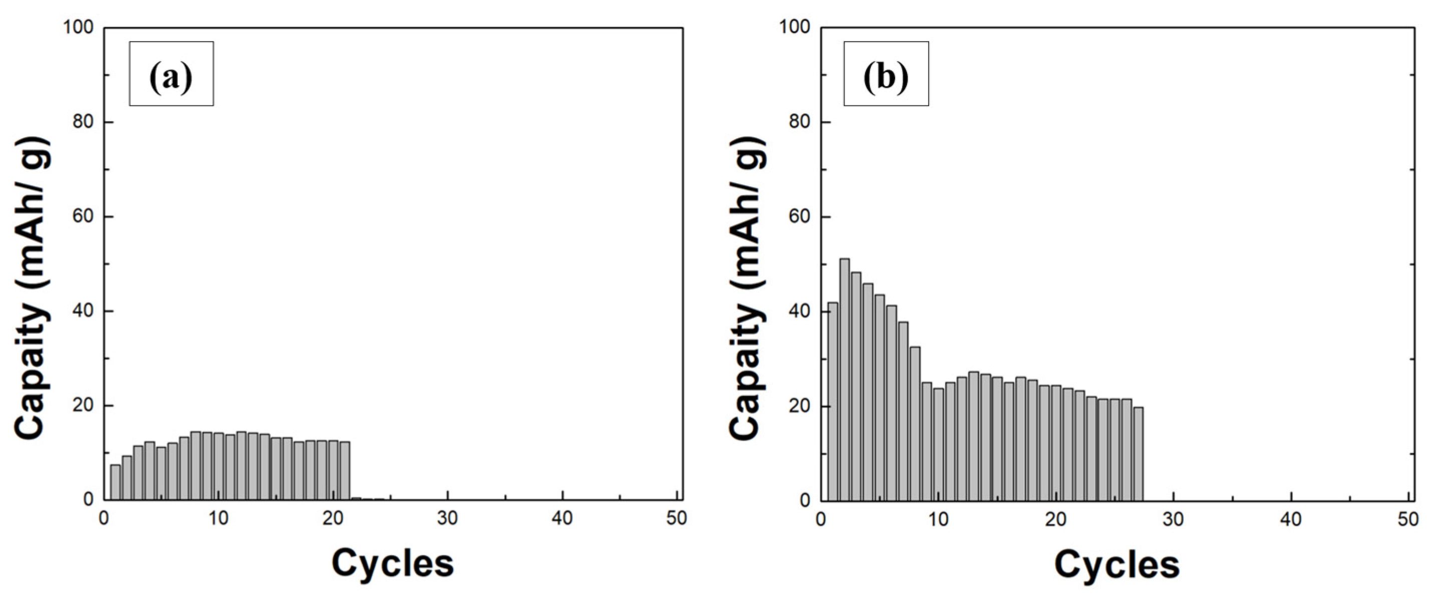
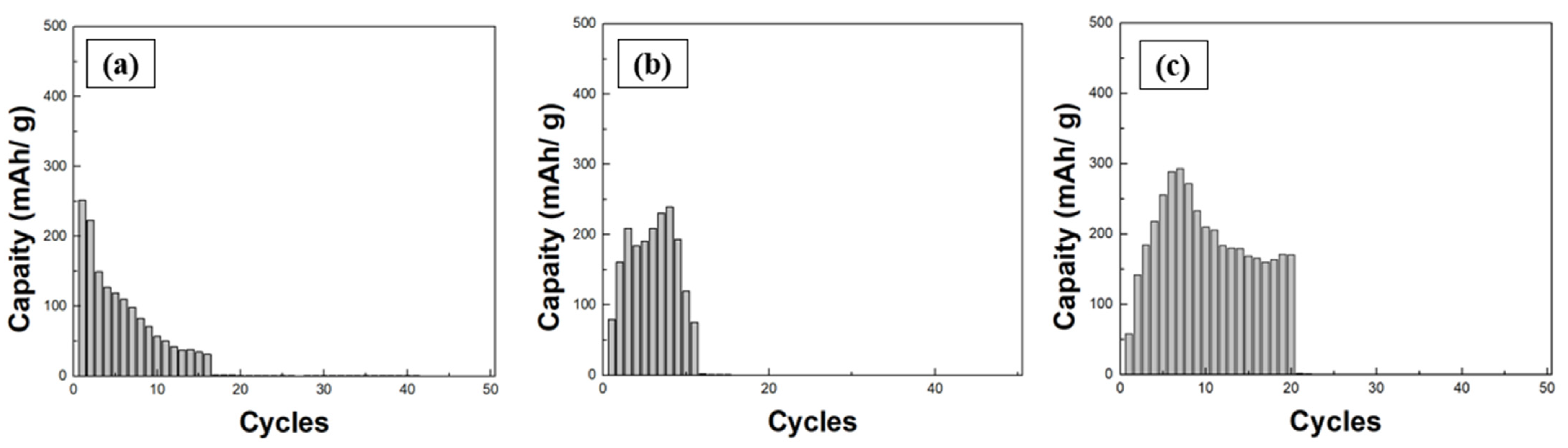
3.3. Charge–Discharge Cycle Characteristics and Ion Migration Mechanisms

The electrical data are summarized as follows: Figure 6 shows the nickel foil without coating as anode and Figure 11 shows the aluminum alloy-coated nickel foil as anode. The modified GFN cathode was paired with the Ingot B electrolyte and the TE ASM/Ni anode to assemble a BT cell. The cell was charged at a constant voltage of 12 V for 10 min, followed by charge–discharge cycling at a constant current of 0.05 mA, as illustrated in Figure 12. The charge–discharge cycling data for the GFN/Ingot B/TE ASM/Ni battery system showed that the maximum specific capacity reached 710 mAh g−1 during the 6th cycle, with the capacity stabilizing by the 30th cycle. Compared to Figure 11, the combination of GFN and TE ASM/Ni demonstrated excellent compatibility, extending the initial 20-cycle lifespan to over 100 cycles. A stable specific capacity of 60–110 mAh g−1 was maintained over the subsequent 50 cycles, indicating the solid-state aluminum battery’s impressive stability [28].
The ion transport pathways in the all-solid-state battery (GFN/Ingot B/TE ASM/Ni) were investigated by dismantling the sandwich structure after completing 100 charge–discharge cycles. EDAX analysis was conducted to examine the surface elements [25]. Additionally, studies were conducted at the interface between the cathode and electrolyte to confirm whether active materials were transported to the electrode surface under applied external voltage. At the same time, the anode was examined at the original coating surface, with the sampling locations indicated in Figure 13 (blue areas). Figure 14 illustrates the surface morphology of the cathode and anode post-charge–discharge cycling. The cathode surface was covered with numerous irregularly shaped deposits, and the anode surface showed signs of coating delamination, suggesting that the aluminum alloy coating may have been consumed or peeled off during battery disassembly.
EDAX analysis was performed at the numbered locations in Figure 14, with the results presented in Table 4, detected aluminum, magnesium, and silicon signals on the discharged cathode surface. These signals originated from (1) the aluminum alloy coating on the anode, the electrochemically active material. Although other cations are present, aluminum ion is still the main contributor. (2) The sodium-based magnesium silicate electrolyte, whose components are transported to the cathode surface under high operating voltage. A silicon signal, influential in the surface deposits, alongside the P, O, and Na signals from the original GFN, suggests that active ions preferentially migrate to the crystalline regions of sodium phosphate within the battery. This confirms that soaking the cathode in a saturated sodium phosphate solution is an effective method for modification, significantly enhancing its ionic conductivity [22].
On the discharged anode surface, signals from the underlying nickel substrate were detected, indicating the gradual depletion of the aluminum alloy coating. The experiment successfully identified the ion transport pathways during the charge–discharge process, as depicted in Figure 15. During charging, aluminum and magnesium ions and composition ions of sodium-based magnesium silicate migrate from the TE ASM/Ni and intercalate into the GFN under the applied voltage. During discharge, cations travel from the GFN back to the TE ASM/Ni, thus completing an entire charge–discharge cycle. Based on Table 4, aluminum ions are the main electrochemically active substance. Therefore, the main reactions of the positive–negative charging and discharging process are as follows:
  • Charging process
  • Negative electrode: Al(s) → Al1−x(s) + x Al3+ + 3x e
  • Positive electrode: x Al3+ + C6(s) + 3x e → AlxC6(s)
  • Full battery reaction: Al(s) + C6(s) → AlxC6(s) + Al1−x(s)
  • Discharging process
  • Negative electrode: AlxC6(s) → x Al3+ + C6(s) + 3x e
  • Positive electrode: Al1−x(s) + x Al3+ + 3x e → Al(s)
  • Full battery reaction: AlxC6(s) + Al1−x(s) → Al(s) + C6(s)
Figure 15. Schematic diagram of the full cell reaction during charging and discharging.
Jcs 09 00166 g015
Since no alloying effects were observed between silicon and nickel in this study, the primary cause is attributed to the brief duration of the thermal deposition process, which was insufficient for the high-melting-point silicon to evaporate and form a coating layer. Future experiments will employ more efficient co-deposition techniques, such as powder thermal spraying, to achieve silicon co-deposition onto the substrate. Additionally, the short deposition time in this study is needed to provide adequate thermal energy for solid-state diffusion between the aluminum alloy coating and the nickel foil. Consequently, no Al-Ni IMCs formed at the coating interface, preventing an evaluation of their contributions. Future work will incorporate vacuum heat treatment to promote the formation of Al-Ni IMCs in the deposited electrodes, thereby establishing an interfacial layer and exploring its electrochemical effects in solid-state aluminum batteries.

3.4. Large-Scale Module Battery and Motor–Fan Unit

A polymer film of mixed silicate was thermally pressed into a flexible solid electrolyte sheet (BCD) with a thickness of 0.25 mm. This electrolyte was paired with the TE ASM/Ni anode and the GFN cathode, using an aluminum sheet as the cathode current collector, cut to approximately 5 × 10 cm. These components were assembled into a sandwich-structured battery (Figure 1). The performance characteristics of the all-solid-state battery developed in this study were then evaluated. A cell was charged at a constant voltage of 6 V for 3 min. As shown in Figure 16 and Table 5, the motor–fan module operated for over 5 min (motor operating voltage: 1.5–6 V, operating current: 20 mA), demonstrating the applicability of the solid-state aluminum alloy battery developed in this research.

4. Limitations

The all-solid-state aluminum alloy battery developed in this study, utilizing a graphite film cathode (GFN), sodium-based magnesium silicate electrolyte (Ingot B), and a thermally deposited aluminum–silicon–magnesium/nickel alloy anode (TE ASM/Ni), demonstrates notable advantages such as high specific capacity and extended cycle life. However, several areas still require improvement for practical applications. Specifically, the thermal evaporation method for aluminum alloy electrodes is unsuitable for large-scale production, and the short deposition duration needs to be improved for effectively depositing certain high-melting-point elements. Future research will, therefore, explore innovative powder thermal spraying techniques to address these limitations and facilitate mass production.

5. Conclusions

(1) This study investigated the GF/Ingot B/TE Al alloy/Ni system to assess the feasibility of aluminum alloy solid-state batteries. The findings confirm that an optimal amount of magnesium (below its solubility limit) enhances the alloy’s performance within the solid-state battery, improving charge–discharge cycling efficiency. However, it is essential to note that excessive magnesium leads to the formation of the intermetallic compound Al3Mg2, which increases internal resistance and adversely affects battery performance.
(2) In the GF/Ingot B/TE Al alloy/Ni system, the cathode GF was modified using a sodium phosphate solution method, which enhanced ionic conductivity without compromising electrical conductivity, resulting in the formation of GFN. The surface of GFN developed sodium phosphate crystals, and the high-stability covalent bonds (P-O) facilitated the detachment of ions from the cathode while preserving structural integrity.
(3) The modified cathode GFN exhibits excellent compatibility with the aluminum alloy anode TE ASM/Ni. When coupled with sodium-based magnesium silicate as a solid electrolyte, the maximum specific capacity increased to approximately 700 mAh g−1. At the same time, the cycle life improved from 20 to over 100 cycles, demonstrating remarkable stability. Additionally, a single motor–fan module charged at 6 V for 3 min could operate for over 5 min, confirming the practicality of the solid-state aluminum alloy battery.

Author Contributions

J.-Y.L. contributed to the investigation, formal analysis, and writing—original draft preparation. B.-D.W. contributed to the methodology, conceptualization, writing—review and editing, and supervision. F.-Y.H. contributed to the methodology, writing—review and editing, supervision, and project administration. All authors have read and agreed to the published version of the manuscript.

Funding

This research received no external funding.

Data Availability Statement

The data presented in this study are available on request from the corresponding author.

Acknowledgments

The authors express their gratitude to the National Cheng Kung University and the Ministry of Science and Technology of Taiwan for supporting this study financially.

Conflicts of Interest

The authors declare no conflicts of interest.

References

  1. Kim, T.; Song, W.; Son, D.Y.; Ono, L.K.; Qi, Y. Lithium-ion batteries: Outlook on present, future, and hybridized technologies. J. Mater. Chem. A 2019, 7, 2942–2964. [Google Scholar] [CrossRef]
  2. Shi, C.; Wang, T.; Liao, X.; Qie, B.; Yang, P.; Chen, M.; Wang, X.; Srinivasan, A.; Cheng, Q.; Ye, Q.; et al. Accordion-like stretchable Li-ion batteries with high energy density. Energy Storage Mater. 2019, 17, 136–142. [Google Scholar]
  3. Chen, Y.; Kang, Y.; Zhao, Y.; Wang, L.; Liu, J.; Li, Y.; Liang, Z.; He, X.; Li, X.; Tavajohi, N.; et al. A review of lithium-ion battery safety concerns: The issues, strategies, and testing standards. J. Energy Chem. 2021, 59, 83–99. [Google Scholar] [CrossRef]
  4. Zhang, X.; Wang, A.; Liu, X.; Luo, J. Dendrites in lithium metal anodes: Suppression, regulation, and elimination. Acc. Chem. Res. 2019, 52, 3223–3232. [Google Scholar] [CrossRef] [PubMed]
  5. Wu, X.; Ma, J.; Wang, J.; Zhang, X.; Zhou, G.; Liang, Z. Progress, Key Issues, and Future Prospects for Li-Ion Battery Recycling. Glob. Chall. 2022, 6, 2200067. [Google Scholar]
  6. Yang, H.; Li, H.; Li, J.; Sun, Z.; He, K.; Cheng, H.M.; Li, F. The rechargeable aluminum battery: Opportunities and challenges. Angew. Chem. Int. Ed. 2019, 58, 11978–11996. [Google Scholar]
  7. Wang, D.Y.; Wei, C.Y.; Lin, M.C.; Pan, C.J.; Chou, H.L.; Chen, H.A.; Gong, M.; Wu, Y.; Yuan, C.; Angell, M.; et al. Advanced rechargeable aluminium ion battery with a high-quality natural graphite cathode. Nat. Commun. 2017, 8, 14283. [Google Scholar]
  8. Jiang, M.; Fu, C.; Meng, P.; Ren, J.; Wang, J.; Bu, J.; Dong, A.; Zhang, J.; Xiao, W.; Sun, B. Challenges and strategies of low-cost aluminum anodes for high-performance Al-based batteries. Adv. Mater. 2022, 34, 2102026. [Google Scholar]
  9. Li, Q.; Bjerrum, N.J. Aluminum as anode for energy storage and conversion: A review. J. Power Sources 2002, 110, 1–10. [Google Scholar]
  10. Razaz, G.; Arshadirastabi, S.; Blomquist, N.; Örtegren, J.; Carlberg, T.; Hummelgård, M.; Olin, H. Aluminum alloy anode with various iron content influencing the performance of aluminum-ion batteries. Materials 2023, 16, 933. [Google Scholar] [CrossRef]
  11. Zhang, X.; Wang, C.; Yang, W.; Gao, D.; Zhang, Z.; Dong, X. Laser-sintering fabrication of integrated Al/Ni anodes for lithium-ion batteries. RSC Adv. 2022, 12, 13168–13179. [Google Scholar] [CrossRef] [PubMed]
  12. Doche, M.L.; Novel-Cattin, F.; Durand, R.; Rameau, J.J. Characterization of different grades of aluminum anodes for aluminum/air batteries. J. Power Sources 1997, 65, 197–205. [Google Scholar] [CrossRef]
  13. Liu, X.; Zhang, P.; Xue, J. The role of micro-naoscale AlSb precipitates in improving the discharge performance of Al-Sb alloy anodes for Al-air batteries. J. Power Sources 2019, 425, 186–194. [Google Scholar] [CrossRef]
  14. Buckingham, R.; Asset, T.; Atanassov, P. Aluminum-air batteries: A review of alloys, electrolytes and design. J. Power Sources 2021, 498, 229762. [Google Scholar] [CrossRef]
  15. Moghanni-Bavil-Olyaei, H.; Arjomandi, J. Performance of Al–1Mg–1Zn–0.1Bi–0.02In as anode for the Al–AgO battery. RSC Adv. 2015, 5, 91273–91279. [Google Scholar] [CrossRef]
  16. Jeffrey, P.W.; Wojciech, H.; Smith, F.N. Aluminum Anode Alloy. U.S. Patent No. 4,751,086, 14 June 1988. [Google Scholar]
  17. Gao, J.; Fan, H.; Wang, E.; Song, Y.; Sun, G. Exploring the effect of magnesium content on the electrochemical performance of aluminum anodes in alkaline batteries. Electrochim. Acta 2020, 353, 136497. [Google Scholar] [CrossRef]
  18. Zhou, W.; Upreti, S.; Whittingham, M.S. Electrochemical performance of Al–Si–graphite composite as anode for lithium–ion batteries. Electrochem. Commun. 2011, 13, 158–161. [Google Scholar] [CrossRef]
  19. Chang, K.C.; Zhao, J.R.; Hung, F.Y. Effects of hyper-high-temperature solid-solution treatment on microstructure evolution and nanoprecipitation of the Al-Ni-Cu-Fe-Zr-Sc alloy manufactured by selective laser melting. J. Alloys Compd. 2021, 883, 160781. [Google Scholar] [CrossRef]
  20. Yu, X.; Manthiram, A. A review of composite polymer-ceramic electrolytes for lithium batteries. Energy Storage Mater. 2021, 34, 282–300. [Google Scholar] [CrossRef]
  21. Chen, Z.Y.; Hung, F.Y.; Zhao, J.R. A new iron battery technology: Charge-discharge mechanism of ferrous chloride and ferric oxide electrolyte in all solid-state iron-graphite batteries. Mater. Sci. Eng. B 2024, 303, 117305. [Google Scholar] [CrossRef]
  22. Lim, C.H.; Jung, Y.H.; Yeom, S.J.; Lee, H.W.; Kim, D.K. Encapsulation of lithium vanadium phosphate in reduced graphene oxide for a lithium-ion battery cathode with stable elevated temperature performance. Electrochim. Acta 2017, 253, 208–217. [Google Scholar] [CrossRef]
  23. Winter, M.; Besenhard, J.O.; Spahr, M.E.; Novak, P. Insertion electrode materials for rechargeable lithium batteries. Adv. Mater. 1998, 10, 725–763. [Google Scholar]
  24. Adhitama, E.; Dias Brandao, F.; Dienwiebel, I.; Bela, M.M.; Javed, A.; Haneke, L.; Stan, M.C.; Winter, M.; Gomez-Martin, A.; Placke, T. Pre-lithiation of silicon anodes by thermal evaporation of lithium for boosting the energy density of lithium ion cells. Adv. Funct. Mater. 2022, 32, 2201455. [Google Scholar]
  25. Huang, B.C.; Fan, W.C.; Hung, F.Y. Study on microstructure and charge–discharge mechanism of all solid-state indium-graphite batteries. Energy Storage 2024, 6, e544. [Google Scholar]
  26. Swain, T. Synthesis, characterization and thermal property of {Cu3(PO4)2·2H2O.; Na3PO4; NaHSO4·H2O}. Sol. Energy 2018, 159, 369–374. [Google Scholar]
  27. Okamoto, H. Al-Mg (aluminum-magnesium). J. Phase Equilibria Diffus. 1998, 19, 598. [Google Scholar] [CrossRef]
  28. Abu Nayem, S.M.; Ahmad, A.; Shaheen Shah, S.; Saeed Alzahrani, A.; Saleh Ahammad, A.J.; Aziz, M.A. High Performance and Long-cycle Life Rechargeable Aluminum Ion Battery: Recent Progress, Perspectives and Challenges. Chem. Rec. 2022, 22, e202200181. [Google Scholar]
Figure 1. Schematic diagram of the sandwich structure of a battery.
Jcs 09 00166 g001
Figure 2. Structure diagram of the BT cell.
Jcs 09 00166 g002
Figure 3. Surface morphology of the (a) GF sheet and (b,c) GFN sheet.
Jcs 09 00166 g003
Figure 4. XRD pattern of GF sheet and GFN sheet.
Jcs 09 00166 g004
Figure 5. FTIR spectrum analysis of the GF and GFN sheets.
Jcs 09 00166 g005
Figure 6. Cyclic performance of (a) Ni/Ingot B/GF and (b) Ni/Ingot B/GFN.
Jcs 09 00166 g006
Figure 7. XRD pattern of the (a) Ni substrate, (b) Al powder, (c) Al-5Mg powder, and (d) Al-10Si-1Mg powder.
Jcs 09 00166 g007
Figure 8. Surface morphology of the (a) Ni substrate, (b,c) TE Al/Ni sheet, (d,e) TE AM/Ni sheet, and (f,g) TE ASM/Ni sheet.
Jcs 09 00166 g008aJcs 09 00166 g008b
Figure 9. XRD pattern of the TE Al/Ni, TE AM/Ni, and TE ASM/Ni specimens.
Jcs 09 00166 g009
Figure 10. (a) Cross-section profile with (b) Al, (c) Si, and (d) Mg (e) Ni elemental mapping by the electron probe microanalyzer of the TE ASM/Ni electrode.
Jcs 09 00166 g010
Figure 11. Cyclic performance of (a) GF/Ingot B/TE Al/Ni, (b) GF/Ingot B/TE AM/Ni, and (c) GF/Ingot B/TE ASM/Ni.
Jcs 09 00166 g011
Figure 12. Cyclic performance of GFN/Ingot B/TE ASM/Ni.
Jcs 09 00166 g012
Figure 13. Schematic diagram of energy dispersive X-ray spectroscopy analysis of GFN and the TE ASM/Ni surface after charging and discharging.
Jcs 09 00166 g013
Figure 14. Surface morphology of (a) GFN after the 50-turn charge–discharge cycle test and (b) TE ASM/Ni after the 50-turn charge–discharge cycle test.
Jcs 09 00166 g014
Figure 16. Schematic diagram of the large-scale module battery and motor–fan unit.
Jcs 09 00166 g016
Table 1. Energy dispersive X-ray analysis (EDAX) of GF and GFN.
MaterialC (wt. %)O (wt. %)Na (wt. %)P (wt. %)
GF100.00.00.00.0
GFN14.541.726.117.7
Table 2. Resistivity measurement of the electrode.
ElectrodeResistivity (Ω × cm)
GF7.813 × 10−4
GFN6.970 × 10−4
Ni5.361 × 10−5
TE Al/ Ni6.898 × 10−4
TE AM/ Ni1.568 × 10−3
TE ASM/ Ni7.813 × 10−5
Table 3. Energy dispersive X-ray analysis (EDAX) of the thermal evaporation sample.
ElementAlSiMgONi
1 (wt. %)58.20.00.018.922.9
2 (wt. %)72.40.012.415.20.0
3 (wt. %)77.10.07.715.20.0
4 (wt. %)74.20.06.419.40.0
5 (wt. %)76.60.05.118.20.0
Table 4. Energy dispersive X-ray analysis (EDAX) of the electrode after the 50-turn charge–discharge cycle test.
ElementCOPNaMgAlSiNi
1 (wt. %)98.21.20.30.10.00.00.00.0
2 (wt. %)11.262.511.81.60.711.01.30.0
3 (wt. %)7.97.20.00.60.00.50.083.8
4 (wt. %)0.041.80.00.00.015.60.041.6
Table 5. Duration time of large-scale module battery with the motor–fan unit.
CyclesDuration Time
First5 min 27 s
Second4 min 18 s
Third4 min 25 s
Fourth4 min 57 s
Fifth4 min 26 s
Disclaimer/Publisher’s Note: The statements, opinions and data contained in all publications are solely those of the individual author(s) and contributor(s) and not of MDPI and/or the editor(s). MDPI and/or the editor(s) disclaim responsibility for any injury to people or property resulting from any ideas, methods, instructions or products referred to in the content.

