Article

Evaluation of Mechanical, Thermal, and Tribological Properties of 3D-Printed Nylon (PA6) Hybrid Composites Reinforced with MWCNTs and Carbon Fibers

by
Palaiam Siddikali
and
P. S. Rama Sreekanth
*
School of Mechanical Engineering, VIT-AP University, Amaravati AP 522337, Inavolu, India
*
Author to whom correspondence should be addressed.
J. Compos. Sci. 2025, 9(4), 155; https://doi.org/10.3390/jcs9040155
Submission received: 18 February 2025 / Revised: 15 March 2025 / Accepted: 21 March 2025 / Published: 24 March 2025

Abstract

:
Three-dimensionally-printed carbonfiber-reinforced composites are increasingly replacing thermosetting polymers and metals due to their lightweight structure and enhanced mechanical performance. This investigation examines the mechanical, thermal and tribological characteristics of 3D-printed nylon (PA6) composites reinforced with 0.5 wt.% multi-walled carbon nanotubes (MWCNTs), 15 wt.% short carbon fibers (CF), and a hybrid combination of both, consisting of 0.5 wt.% MWCNTs and 15 wt.% CF. This study focuses on evaluating the individual and synergistic effects of these reinforcements on the performance of nylon-based composites. A series of characterizations, including mechanical, thermal, tribological, morphological and FTIR analyses, are conducted. The tensile and flexural strengths of the hybrid composite are improved by 35% and 42%, respectively, compared to pure nylon. The findings emphasize the substantial influence of hybrid reinforcement on enhancing mechanical, thermal, and tribological properties, providing useful information on the possible utilization of these composites in engineering applications requiring high-performance materials.

1. Introduction

Polyamides, also referred to as nylons, are widely-used engineering thermoplastic materials valued for their exceptional properties. These include high resistance to temperature and corrosion, excellent toughness, high modulus, anti-fatigue performance, and oil-proof characteristics, making them suitable for a broad variety of applications [1]. Among the various polyamides, poly(ε-caprolactam) (PA6), commonly known as polyamide-6 or nylon-6, is a versatile semi-crystalline engineering thermoplastic. It is highly regarded for its exceptional mechanical strength, superior stiffness, and remarkable chemical resistance to various solvents and hydrocarbons [2]. CF-reinforced polymer (CFRP) composites have an increasingly widespread use as structural materials in industries such as aviation, aerospace, defense, and automobiles, where a combination of high strength and low density is crucial [3]. The performance of CFRP is strongly affected by the interface properties between the fibers and the polymer matrix. It is a significant design concern that the unidirectional fiber-reinforced polymer composites exhibit uniform mechanical behavior under transverse deformation, interfacial characteristics, such as interfacial shear strength. A variety of studies have explored how the matrix and interfacial properties influence the mechanical performance of composites, utilizing both experimental and numerical methods [4,5].
The process of 3D printing, which is an additive manufacturing method using material extrusion, is frequently used for the production of thermoplastic polymer composites. This approach offers several advantages, including simple equipment requirements, cost-effectiveness, and the ability to produce complex components with ease [6,7,8]. Short fibers are commonly blended with polymers to produce composites with enhanced properties. Specifically, incorporating carbon fibers into polymer feedstock improves thermal conductivity, reduces thermal expansion, minimizes warping in larger prints, lowers residual stresses within the part, and enhances the dimensional accuracy of printed components [9]. To enhance the mechanical characteristics of 3D-printed thermoplastics, short (discontinuous) or long (continuous) CFs and MWCNTs are commonly used as reinforcements. As a result, 3D-printed composite structures exhibit properties that significantly surpass those of pure thermoplastics. Moreover, the properties of these composites are comparable to metals, making them suitable for various industrial applications, especially when short fibers are used as reinforcement [10].
Alarifi et al. [11] improved the mechanical properties (flexural strength) of nylon reinforced with CF and glass fiber (GF) fabricated by 3D printing. Lu et al. [12] enhanced the mechanical properties (tensile-94%, flexural-111%) of PEEK (polyether-ether-ketone) through the addition of CF fabricated by 3D printing. Islam et al. [13] investigated the fracture behavior of short and continuous CF-reinforced nylon matrix composites under tensile loading. Their study improved tensile strength and modulus, proving that continuous CF is superior to short CF in 3D-printing applications. Palaniappan et al. [14] investigated the mechanical properties (tensile and flexural) of CF-reinforced nylon composites fabricated using 3D printing. Their study found that tensile strength was significantly influenced by printing speed, while impact and flexural strength were primarily affected by layer thickness and raster angle. Uematsu et al. [15] examined the transverse tensile behavior of unidirectional CF-reinforced polyamide 6 (PA6) composites, focusing on the PA6 matrix morphology. Their study highlighted that unidirectional CFs influenced the mechanical behavior under transverse tension. Dubey et al. [16] investigated the mechanical and viscoelastic behavior of short CF-reinforced 3D-printed nylon composites, focusing on the impact of different infill patterns. Their study found that the rectilinear pattern enhanced tensile strength, while the triangular pattern provided better flexural strength. SV et al. [17] investigated the mechanical behavior of PETG and nylon polymers fabricated using Material Extrusion (MEX) in 3D printing. Their study found that the tensile strength of both materials is significantly influenced by printing parameters, including nozzle and bed temperatures, infill densities, printing speeds, and layer heights. Sun et al. [18] investigated the effects of CF content and heat treatment on the mechanical, thermal, and microstructural properties of PA6-CF composites fabricated using 3D printing. They achieved a maximum tensile strength of 163 MPa under optimal heat treatment conditions (120 °C for 7.5 h), representing a 406% increase compared to unreinforced composites. Liu et al. [19] explored strategies to enhance the mechanical properties of continuous fiber-reinforced PA6 by incorporating various nanofillers into the polymer matrix. Their study demonstrated improvements in both tensile strength and modulus. Rashid et al. [20] studied the effect of infill patterns and densities on the mechanical properties of CF-reinforced PA6 composites. Triangular and hexagonal patterns performed better at lower infill densities, while rectangular patterns provided superior strength and elongation at higher densities.
This study investigates the mechanical, thermal, and tribological behavior of MWCNTs-reinforced nylon composites, short CF-reinforced nylon composites, and a hybrid combination, which were produced by 3D printing. The emphasis is placed on the investigation of how these reinforcements, either alone or in combination, influence the strength, stiffness, wear resistance, scratch resistance, and hardness of the composites. Further, thermal properties are analyzed through differential scanning calorimetry (DSC) to see how the reinforcements affect the melting trend of the nylon matrix. Ultimately, this study aims to provide insights into the synergistic effects of MWCNT and CF reinforcements, with potential applications in industries requiring lightweight, high-performance materials.

2. Material and Experimental Characterizations

2.1. Nylon, MWCNTs and CF Specifications

This study utilized thermoplastic nylon polymer (PA6)—a semi-crystalline material obtained from Gujarat State Fertilizers & Chemicals Limited (GSFC), Gujarat, India—as the base material. Amine-functionalized multi-walled carbon nanotubes (MWCNTs) from Shilpa Enterprises, Maharashtra, India and short carbon fibers (CF) with a 3–6 mm length and 7–10 µm diameter from NitPro composites, India were incorporated into the nylon matrix to create nanocomposites and improve the material’s properties. The specifications for the MWCNTs used are detailed in Table 1.

2.2. Filament Extrusion and Specimen Fabrication

The 3D-printing filaments, with a nominal diameter of 1.75 mm, were fabricated by extruding a polymer matrix reinforced with MWCNT, CF, and a hybrid combination of MWCNT and CF. The compositions included 0.5 wt.% MWCNT, 15 wt.% CF, and a hybrid mixture containing 0.5 wt.% MWCNT and 15 wt.% CF. To eliminate moisture, the mixture was vacuum-dried at 80 °C for 3–4 h. The fillers were uniformly dispersed within the polymer matrix using a co-rotating twin-screw extruder (Aasabi/25TS/CO/300/30). The extrusion process was carefully managed, with screw speeds maintained between 36 and 40 rpm, melting temperatures ranging from 240 to 260 °C, and a winding speed of 10 m per minute. The filament’s outer diameter variation was controlled to within ±0.1 mm. Both the pure and reinforced specimens were manufactured using the Markforged Mark Two (Gen 2) FDM 3D printer. Figure 1 illustrates the filament extrusion and 3D-printing process. The specific 3D-printing parameters employed for specimen fabrication are detailed in Table 2.

2.3. Differential Scanning Calorimetry (DSC)

DSC analysis was carried out on pure and reinforced nylon composite specimens in a nitrogen atmosphere using a Perkin Elmer STA 8000, Waltham, MA, USA, from 30 to 300 °C at a temperature rise of 10 °C per minute, and a 300 to 30 °C cooling ramp at 10 °C per minute was performed.

2.4. Tensile Test

Tensile testing of both pure and reinforced nylon composite specimens was performed using a Tinius Olsen H10KL universal testing machine (UTM), Tinus Olsen India Pvt. Ltd. (Uttar Pradesh, India) in accordance with ASTM D638 Type V standards. The tests were conducted at a strain rate of 5 mm/min at ambient temperature. In total, five specimens were evaluated for each test condition, and the average results were documented.

2.5. Flexural Test

Flexural tests were carried out on both pure and reinforced nylon composite specimens using a Tinius Olsen H10KL UTM in a three-point bending arrangement, following ASTM D790 standards. The tests were conducted at a strain rate of 1 mm/min under ambient temperature conditions. Five specimens were tested under each test condition, and the average findings were provided.

2.6. Fourier Transform Infrared Spectroscope (FTIR)

FTIR spectroscopy was carried out on both pure and reinforced nylon composite specimens using the attenuated total reflection (ATR) method. The spectral data were obtained with an Agilent Technologies Cary 630 spectrometer (Santa Clara, CA, USA). In total, 64 scans were recorded across the wavelength range of 600–4000 cm−1. Standard Normal Variate (SNV) normalization was applied to the data. This technique involves subtracting the mean from each spectral intensity value and then dividing by the standard deviation [21,22].

2.7. Surface Morphology (Scanning Electron Microscopy)

The surface morphology and microstructure of the pure nylon and its composite specimens were analyzed after the tensile test using a CARL ZEISS EVO10 machine (Zeiss Microscopy, LLC, White Plains, NY, USA). To examine the surface morphology of the fractured specimens post-tensile testing, the fracture surfaces were coated with gold via sputter coating.

2.8. Tribological Analysis

2.8.1. Wear Characterization

The wear characteristics of pure nylon and its composites were evaluated using a pin-on-disc tribometer (Model TR-20LE, Ducom, Bangalore, India). The tests were conducted under conditions of a 200 rpm rotational speed, a 30 N normal load, and a duration of 30 min. The square specimens were each 8 mm × 8 mm in size and 5 mm thick. For the wear tests, these specimens were firmly affixed to a rectangular holder with adhesive.

2.8.2. Scratch Test

The scratch resistance of the pure nylon and its composite specimens was assessed using a CSM Micro-Scratch Tester (MST) from Neuchatel, Switzerland. The evaluation included both single- and multiple-scratch tests. A conical diamond indenter, featuring a 200 µm diameter and a 120° cone angle, was utilized to create 10 mm long scratches at a speed of 1 mm/min with a normal force of 30 N. All scratches were performed at room temperature. Instantaneous and residual scratch depths were measured for an applied load and number of scratches. The scratch hardness is determined by Equation (1):
H s = 4 P π d 2
where P is the normal force in N and d is the scratch width determined from the software.

2.8.3. Hardness Test

The hardness (measured in HV) of pure nylon and its composite specimens was determined using an RS Scientific FMV1-MC-AT Micro Vickers hardness tester equipped with a diamond indenter. A load of 0.05 kg was applied to the sample surface for a dwell time of 5 s. The hardness value was calculated using the following Equation (2):
H V = 1.889 F d 2
where F represents the applied force (N), and d is the diagonal length of the square indentation (mm).

3. Results and Discussion

3.1. DSC Test Results

Figure 2 shows the effect of MWCNTs, CF, and their hybrid fillers on the melting (Tm) and crystallization (Tc) temperature behavior of a nylon composite by using DSC. For pure nylon, the Tm was recorded at 215.2 °C with a melting enthalpy (ΔHm) of 54.82 J/g. Upon incorporating 0.5 wt% MWCNTs, the Tm increased to 218.3 °C. These observations, along with additional data, are detailed in Table 3. This increase can be attributed to the MWCNTs acting as nucleating agents, promoting enhanced crystallization and increasing the degree of crystallinity in the PA6 matrix. This leads to a more stable crystalline structure, requiring a higher thermal energy input to break the ordered regions during melting, thereby increasing Tm. Additionally, the formation of a MWCNT network within the polymer restricts the molecular motion of polymer chains, limiting their ability to reorganize into a lower-energy state upon heating, further contributing to the observed increase in Tm [23,24,25]. In contrast, the inclusion of 15 wt.% CFs into the nylon matrix resulted in an increase in Tm to 219.3 °C. This increase is primarily due to the disruptive effect of the CFs on the crystalline structure of nylon. The fibers interfere with the orderly packing of the polymer chains, leading to an increase in crystallinity and, consequently, a higher melting temperature [15,26,27].
Moreover, the hybrid composition, which combined MWCNTs and CFs, exhibited a Tm of 221.2 °C, slightly higher than that of the 15 wt.% CF composites. This behavior suggests that while the CFs enhance the crystalline lattice, the presence of MWCNTs may form a reinforcing network that further improves the structural integrity and thermal stability of the nylon matrix.
Furthermore, the heat of fusion, indicative of a polymer’s crystallinity, is determined by integrating the area under the melting temperature (Tm) peaks in DSC curves. For nylon (PA6), the heat of fusion for a 100% crystalline sample is reported as 188 J/g [26,28]. This value serves as a reference to calculate the weight percentage crystallinity of both virgin PA6 and its composites, such as those reinforced with MWCNTs, CF, or a combination of both, as shown in Figure 3. The degree of crystallinity (Xc) of a polymer can be calculated using the following Equation (3):
X c = H m H f ( 1 w f ) × 100 %
In this formula, Xc represents the degree of crystallinity, ΔHm is the measured melting enthalpy of the composite, ΔHf denotes the enthalpy of fusion for 100% crystalline PA6 (taken as 188 J/g), and wf is the mass fraction of carbon fiber in the composite.

3.2. Tensile Test Results

Figure 4 illustrates the tensile properties of various nylon composites, highlighting the impact of different reinforcements on their tensile performance. Pure nylon exhibits excellent ductility, with a strain capacity exceeding 300% and an ultimate tensile strength of approximately 40 MPa. In contrast, the inclusion of 0.5 wt.% MWCNT improves the tensile strength to 47.4 MPa but significantly reduces ductility. This strength enhancement is a result of the uniform dispersion of MWCNTs and enhanced interfacial adhesion between the MWCNTs and the nylon polymer matrix, thus facilitating load transfer and stress distribution in the nanocomposite. The decreased elongation is a result of the interference by MWCNT particles with polymer chain mobility. This constrained mobility results in additional resistance to the alignment of the chains upon loading, which is vital for high elongation [27,29].
On the other hand, the incorporation of 15 wt.% CF substantially enhances tensile strength to 52.2 MPa due to its reinforcing effect, though it reduces the strain at break, indicating a stiffening of the composite [30]. The hybrid combination of 0.5 wt.% MWCNT and 15 wt.% CF results in the highest tensile strength of 60.9 MPa among the 0.5 and 15 wt.% MWCNT and CF tested. The increased tensile strength might be attributed to the proper alignment of CF within the polymer matric, as well as its even distribution, balance between effective fiber–matrix adhesion, orientation, and. This enhances elastic modulus, facilitates effective load carrying, and ensures efficient load transfer between the CF and the matrix. However, the strain capacity remains similar to that of the CF-reinforced composite, suggesting that the reduction in ductility is primarily governed by the CF content. Overall, the tensile strength improved by 16, 24, and 35% with the addition of 0.5 wt.% MWCNT, 15 wt.% CF, and the hybrid reinforcement, respectively, compared to pure nylon.
To understand the underlying mechanisms of reinforcement effects on the mechanical properties of the polymer composite, fractography analysis was performed. Figure 5 presents SEM micrographs of the fractured surfaces of pure nylon and its composites after tensile testing. Figure 5a shows the fractured surface of pure nylon, characterized by a rough texture with visible fractures and irregularities. On the other hand, Figure 5b reveals significant changes in the fracture surface topography of the nanocomposite, showing that the presence of functionalized MWCNT promotes the polymer’s interfacial adhesion thereby enhancing the mechanical properties by improving load transfer and stress distribution within the nanocomposite. Furthermore, Figure 5c,d depict CF stacked with nylon, exhibiting good distribution within the matrix. This uniform distribution contributes to improved mechanical properties and also plays a critical role in enhancing the interlaminar fracture toughness of the composite. Failure mechanisms such as debonding, fiber breakage, and fiber pull-out are observed in the samples.

3.3. Flexural Test Results

Figure 6 illustrates the flexural behavior of pure nylon and its composites with different reinforcements. Pure nylon exhibits a flexural stress of 73.1 MPa. The addition of 0.5 wt.% MWCNT improves the flexural strength to 108 MPa, indicating a significant enhancement compared to pure nylon. This enhancement is credited to the even distribution of MWCNTs and the improved bonding at the interface with the polymer matrix, which facilitates better load transfer and stress distribution in the nanocomposite. A further enhancement is observed with the addition of 15 wt.% CF, which increases the composite’s flexural strength to 112 MPa. The hybrid combination of 0.5 wt.% MWCNT and 15 wt.% CF achieves the highest flexural stress of 127 MPa, demonstrating a synergistic improvement in mechanical performance. This substantial increase in strength can be attributed to the proper alignment and even distribution of carbon fibers within the polymer matrix, which enhances stiffness, load-carrying capacity, and efficient load transfer. Additionally, this combination achieves a high strength-to-weight ratio.
Overall, the flexural strength is improved by 32%, 35%, and 42% with the addition of 0.5 wt.% MWCNT, 15 wt.% CF, and the hybrid reinforcement, respectively, compared to pure nylon. These results highlight the superior performance of the hybrid composite, demonstrating the effectiveness of combining reinforcements to enhance nylon’s mechanical properties.

3.4. FTIR Analysis

Figure 7 depicts the FTIR spectra of pure nylon and its composites, which establish the anticipated chemical structure of polyamide polymers. The amine primary group’s N-H bending vibration is represented by the 3296 cm−1 absorption band. The C-H symmetric and asymmetric stretching vibrations are represented by the linked bands at 2855 cm−1 and 2930 cm−1, respectively. The distinctive bands of the amide groups occur at 1635 cm−1 (amide I, C=O stretching vibration), 1534 cm−1 (amide II, C-N stretching and CO-N-H bending vibration), 1461 cm−1 (amide III, C-N stretching and C-H in-plane bending vibration), and 1262 cm−1 (amide IV, C-CO stretching vibration) [30].
The incorporation of 0.5 wt.% MWCNT into the nylon matrix results in a slight increase in the intensity of the N–H at 3296 cm−1 and Amide I peaks at 1534 cm−1 compared to pure nylon. This suggests interactions between the MWCNT and the nylon matrix, likely due to hydrogen bonding or physical interactions, which restrict chain mobility and enhance the structural stability of the polymer. In contrast, the addition of 15 wt.% CF leads to a slight reduction in the intensity of the Amide I and N–H peaks. This decrease in peak intensity indicates a partial disruption of hydrogen bonding within the matrix, likely caused by the fiber–matrix interactions [14,31,32]. Furthermore, the hybrid combination of MWCNT and CF demonstrates a partial recovery in the intensity of the N–H stretching peak compared to the CF-only composition. This suggests that the reinforcing effect of MWCNT partially counteracts the disruption caused by CF, contributing to improved structural retention in the hybrid system.

3.5. Tribological Analysis

3.5.1. Wear Rate Analysis

Figure 8 presents an analysis of the tribological performance of nylon and its composites. Initially, all specimens exhibit a rapid increase in wear rate within the first 200 s, indicating an initial wear phase. Among them, pure nylon demonstrates the highest wear rate, peaking at approximately 60 μm. This highlights its susceptibility to wear under operational conditions, primarily due to adhesive wear, fatigue wear, and plowing mechanisms. The increased wear rate in pure nylon can be attributed to its relatively low hardness and lower fatigue resistance. Additionally, nylon’s tendency to absorb moisture and soften at elevated temperatures may further contribute to its higher wear rate. The incorporation of 0.5 wt.% MWCNTs into the nylon matrix significantly reduces the wear rate, which stabilizes at around 50 μm after the initial phase. The subsequent wear is mainly due to abrasive interactions between the nylon composite (N+MWCNT) surface and the metal disc. This reduction in wear rate is attributed to the formation of a protective layer by MWCNTs, which minimizes direct contact with the counterface. Additionally, the increased hardness and stiffness of the composite lead to reduced deformation under the load, limiting plastic flow. Improved thermal conductivity further enhances performance by efficiently dissipating heat, thereby preventing thermal degradation.
Similarly, the nylon composite reinforced with 15 wt.% CF exhibits an even lower wear rate of approximately 30 μm, demonstrating a substantial improvement in wear resistance. This enhancement is due to the strong load-bearing structure provided by carbon fibers, which reduces surface wear and improves resistance to deformation. Furthermore, CF acts as a reinforcing agent, lowering friction and minimizing abrasive wear [33,34]. Notably, the hybrid combination of both MWCNT and CF yields the best results, with wear rates stabilizing at around 10 to 15 μm. This substantial enhancement in performance suggests that the synergistic effect of MWCNT and CF significantly improves the tribological properties of nylon composites. The transition to a steady state, observed around 400 s, indicates that the composites stabilize with minimal fluctuations in wear rate.

3.5.2. Coefficient of Friction (COF)

Figure 9 illustrates the variation of the COF with distance for pure nylon and its composites. Initially, all specimens exhibit a sharp peak in COF before stabilizing, reaching equilibrium after approximately 500 m of sliding distance. Pure nylon (N) shows the highest COF, with a static COF of 0.271 and a stabilized kinetic COF of 0.238. The addition of MWCNT significantly reduces both static and kinetic COF to approximately 0.253 and 0.220, respectively, making it the most effective in lowering friction. The inclusion of CF results in a slightly lower COF than pure nylon, with static and kinetic values around 0.264 and 0.226, respectively. The CF content in the nylon composite further reduces the COF compared to pure nylon, likely due to CF’s unique structure. As a graphitized carbon, CF has hexagonal planes aligned perpendicular to the fiber axis, which is believed to contribute to friction reduction when sliding against steel [35]. Meanwhile, the combination of MWCNT and CF yields an intermediate COF, with static and kinetic values of 0.270 and 0.199, respectively, due to the synergetic effect of MWCNT and CF.

3.5.3. Scratch Test

The scratch test results are presented in Figure 10. Both MWCNT and CF fillers are shown to improve scratch resistance. Pure nylon exhibits greater penetration and higher plastic deformation with a scratch hardness (Hs) of 78. However, the addition of MWCNTs to nylon reduces both penetration depth and plastic deformation with a Hs of 117. This improvement is due to the lubricating effect of MWCNTs, which lower the coefficient of friction (COF) in the composite. Additionally, the reduced breaking strength of the composite, which is linked to the MWCNT content, also contributes to the lower COF by decreasing the tangential force during scratching, as the friction coefficient is directly proportional to the tangential force [35,36,37,38,39].
In contrast, the N+CF composite shows better performance in terms of scratch width and depth, with an increase in Hs as shown in Figure 10(ii) [39]. This improvement can be attributed to the greater rigidity of CFs, which help distribute stresses more evenly across the nylon matrix and contribute to a reduction in COF. Furthermore, the hybrid nylon composite, which combines both MWCNT and CF, exhibits the highest Hs of 524, with the smallest width, depth, and plastic deformation among all the materials. This is due to the synergistic effect of MWCNTs and CFs.

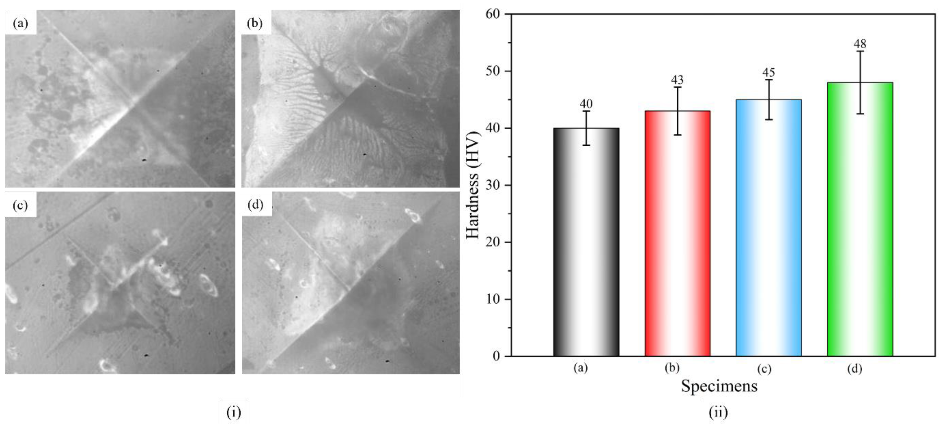
3.5.4. Hardness Test

The Vickers hardness of nylon and its composites, along with the corresponding micro-indentations, is illustrated in Figure 11. The hardness increases with the incorporation of reinforcements into the nylon matrix. Pure nylon exhibits a hardness of 40 HV, while the addition of MWCNTs raises it to 43 HV. Similarly, CF reinforcement further enhances the hardness to 45 HV [33], and the hybrid combination of both reinforcements achieves the highest value of 48 HV. The improvements in hardness result from the enhanced load-bearing capacity, improved interfacial bonding, and reduced creep and plastic deformation. The synergistic effect of MWCNTs and CF contributes to the maximum hardness enhancement in nylon composites.

4. Conclusions

The work examined the influence of MWCNT and CF individually and their hybrid, on the mechanical, thermal, and tribological properties of PA6 composites at various weight percentages. All the test specimens were prepared via 3D printing followed by diverse characterizations. The main conclusions are as follows:
  • Mechanical properties improved due to the synergistic effect of MWCNTs and CFs. The hybrid reinforcement (0.5 wt.% MWCNTs and 15 wt.% CF) significantly enhanced tensile and flexural properties through proper alignment and even distribution within the polymer matrix.
  • The addition of MWCNTs and CFs to the nylon interferes with the orderly packing of the polymer chains, leading to an increase in crystallinity and, consequently, a higher melting temperature
  • The synergistic effect of MWCNTs and CF contributes to the maximum hardness enhancement in nylon composites. The improvements in hardness result from the enhanced load-bearing capacity and improved interfacial bonding. This could result in enhanced creep resistance and reduced plastic deformation.
  • The presence of MWCNT and CF has considerably lowered the wear during the run-in phase thereby marking a lower static coefficient of friction and subsequently a lower kinetic friction coefficient.
  • Tangential force during scratching is lowered, which reduces the plastic deformation and thereby enhances the composites’ performance. The penetration depth and plastic deformation of the composite samples were observed to be reduced due to increased scratch hardness.

Author Contributions

P.S.: conceptualization, methodology, software, validation, testing, and writing—original draft preparation. P.S.R.S.: visualization, investigation, supervision, and writing—reviewing and editing. All authors have read and agreed to the published version of the manuscript.

Funding

This research received no external funding.

Institutional Review Board Statement

Not applicable.

Informed Consent Statement

Not applicable.

Data Availability Statement

Made on request.

Acknowledgments

The authors gratefully acknowledge the invaluable technical support received from Sivanagaraju, VIT-AP university during the sample fabrication and also for his in-depth technical discussion which helped in results analysis. The authors also declare that they have no known competing financial interests or personal relationships that could have appeared to influence the work reported in this paper.

Conflicts of Interest

The authors declare no conflicts of interest.

Abbreviations

The following abbreviations are used in this manuscript:
NNylon
PA6Polyamide
MWCNTMulti-walled carbon nanotubes
CFCarbon nanofiber
HsScratch hardness
TmMelting point

References

  1. Zhang, Z.; Huang, K.; Liu, Z. Synthesis of high molecular weight nylon 46 in supercritical carbon dioxide. Macromolecules 2011, 44, 820–825. [Google Scholar] [CrossRef]
  2. Meincke, O.; Kaempfer, D.; Weickmann, H.; Friedrich, C.; Vathauer, M.; Warth, H. Mechanical properties and electrical conductivity of carbon-nanotube filled polyamide-6 and its blends with acrylonitrile/butadiene/styrene. Polymer 2003, 45, 739–748. [Google Scholar] [CrossRef]
  3. Zucchelli, A.; Focarete, M.L.; Gualandi, C.; Ramakrishna, S. Electrospun nanofibers for enhancing structural performance of composite materials. Polym. Adv. Technol. 2011, 22, 339–349. [Google Scholar] [CrossRef]
  4. González, C.; Llorca, J. Mechanical behavior of unidirectional fiber-reinforced polymers under transverse compression: Microscopic mechanisms and modeling. Compos. Sci. Technol. 2007, 67, 2795–2806. [Google Scholar] [CrossRef]
  5. Wang, X.; Zhang, J.; Wang, Z.; Zhou, S.; Sun, X. Effects of interphase properties in unidirectional fiber reinforced composite materials. Mater. Des. 2011, 32, 3486–3492. [Google Scholar] [CrossRef]
  6. Sanei, S.H.R.; Popescu, D. 3D-printed carbon fiber reinforced polymer composites: A systematic review. J. Compos. Sci. 2020, 4, 98. [Google Scholar] [CrossRef]
  7. Fasel, U.; Keidel, D.; Baumann, L.; Cavolina, G.; Eichenhofer, M.; Ermanni, P. Composite additive manufacturing of morphing aerospace structures. Manuf. Lett. 2020, 23, 85–88. [Google Scholar] [CrossRef]
  8. Khatoon, S.; Khandelwal, A.; Raj, A.; Ahmad, G. Fabrication of FFF 3D-printed surfaces for PMMA-based biomedical device employing the pre-processing optimization to eliminate the post-processing steps. Prog. Addit. Manuf. 2023, 9, 1003–1014. [Google Scholar] [CrossRef]
  9. van de Werken, N.; Hurley, J.; Khanbolouki, P.; Sarvestani, A.N.; Tamijani, A.Y.; Tehrani, M. Design considerations and modeling of fiber reinforced 3D printed parts. Compos. B Eng. 2019, 160, 684–692. [Google Scholar] [CrossRef]
  10. van de Werken, N.; Tekinalp, H.; Khanbolouki, P.; Ozcan, S.; Williams, A.; Tehrani, M. Additively manufactured carbon fiber-reinforced composites: State of the art and perspective. Addit. Manuf. 2020, 31, 100962. [Google Scholar] [CrossRef]
  11. Alarifi, I.M. A performance evaluation study of 3d printed nylon/glass fiber and nylon/carbon fiber composite materials. J. Mater. Res. Technol. 2022, 21, 884–892. [Google Scholar] [CrossRef]
  12. Lu, S.; Zhang, B.; Niu, J.; Yang, C.; Sun, C.; Wang, L.; Li, D. Effect of fiber content on mechanical properties of carbon fiber-reinforced polyether-ether-ketone composites prepared using screw extrusion-based online mixing 3D printing. Addit. Manuf. 2024, 80, 103976. [Google Scholar] [CrossRef]
  13. Islam, M.N.; Baxevanakis, K.P.; Silberschmidt, V.V. Mechanical characterisation of AM nylon-matrix carbon-fibre-reinforced composite in tension. Mater. Today Proc. 2022, 70, 50–54. [Google Scholar]
  14. Palaniappan, A.K.; Krishnan, R.K.; Vasanaperumal, P.; Rajendiran, K. Analysis of the Mechanical Characteristics and Properties of a Carbon Fiber–Nylon Composite Influence of the Factors of the Fused Deposition Modeling. J. Mater. Eng. Perform. 2024, 33, 12976–12989. [Google Scholar] [CrossRef]
  15. Uematsu, H.; Kurita, D.; Nakakubo, S.; Yamaguchi, A.; Yamane, M.; Kawabe, K.; Tanoue, S. Mechanical behavior of unidirectional carbon fiber-reinforced polyamide 6 composites under transverse tension and the structure of polyamide 6 among carbon fibers. Polym. J. 2020, 52, 1195–1201. [Google Scholar] [CrossRef]
  16. Dubey, D.; Singh, S.P.; Behera, B.K. Mechanical, thermal, and microstructural analysis of 3D printed short carbon fiber-reinforced nylon composites across diverse infill patterns. Prog. Addit. Manuf. 2024, 10, 1671–1689. [Google Scholar] [CrossRef]
  17. SV, L.S.; Karthick, A.; Dinesh, C. Evaluation of mechanical properties of 3D printed PETG and Polyamide (6) polymers. Chem. Phys. Impact 2024, 8, 100491. [Google Scholar] [CrossRef]
  18. Sun, B.; Mubarak, S.; Zhang, G.; Peng, K.; Hu, X.; Zhang, Q.; Wu, L.; Wang, J. Fused-Deposition Modeling 3D Printing of Short-Cut Carbon-Fiber-Reinforced PA6 Composites for Strengthening, Toughening, and Light Weighting. Polymers 2023, 15, 3722. [Google Scholar] [CrossRef]
  19. Liu, Z.; Shi, J.; Wang, Y. Evaluating tensile properties of 3d printed continuous fiber reinforced nylon 6 nanocomposites. In Proceedings of the International Manufacturing Science and Engineering Conference, College Station, TX, USA, 18–22 June 2018; American Society of Mechanical Engineers: New York, NY, USA, 2018; Volume 51357, p. V001T01A031. [Google Scholar]
  20. Al Rashid, A.; Ikram, H.; Koç, M. Additive manufacturing and mechanical performance of carbon fiber reinforced Polyamide-6 composites. Mater. Today Proc. 2022, 62, 6359–6363. [Google Scholar] [CrossRef]
  21. Agustika, D.K.; Mercuriani, I.; Purnomo, C.W.; Hartono, S.; Triyana, K.; Iliescu, D.D.; Leeson, M.S. Fourier transform infrared spectrum pre-processing technique selection for detecting PYLCV-infected chilli plants. Spectrochim. Acta Part A Mol. Biomol. Spectrosc. 2022, 278, 121339. [Google Scholar] [CrossRef]
  22. Gautam, R.; Vanga, S.; Ariese, F.; Umapathy, S. Review of multidimensional data processing approaches for Raman and infrared spectroscopy. EPJ Tech. Instrum. 2015, 2, 8. [Google Scholar] [CrossRef]
  23. Phang, I.Y.; Ma, J.; Shen, L.; Liu, T.; Zhang, W.D. Crystallization and melting behavior of multi-walled carbon nanotube-reinforced nylon-6 composites. Polym. Int. 2006, 55, 71–79. [Google Scholar] [CrossRef]
  24. Faghihi, M.; Shojaei, A.; Bagheri, R. Characterization of polyamide 6/carbon nanotube composites prepared by melt mixing-effect of matrix molecular weight and structure. Compos. Part B Eng. 2015, 78, 50–64. [Google Scholar]
  25. Chafidz, A.; Latief, F.H.; Al-Fatesh, A.S.; Kaavessina, M. Crystallization and thermal stability of polypropylene/multi-wall carbon nanotube nanocomposites. Philos. Mag. Lett. 2016, 96, 367–374. [Google Scholar] [CrossRef]
  26. Liu, J.; He, L.; Yang, D.; Liang, J.; Zhao, R.; Wang, Z.; Li, X.; Chen, Z. Effects of Carbon Fiber Content on the Crystallization and Rheological Properties of Carbon Fiber-Reinforced Polyamide 6. Polymers 2024, 16, 2395. [Google Scholar] [CrossRef]
  27. da Silva, F.S.; Luna, C.B.; da Silva Barbosa Ferreira, E.; de Matos Costa, A.R.; Wellen, R.M.; Araújo, E.M. Polyamide 6 (PA6)/carbon nanotubes (MWCNT) nanocomposites for antistatic application: Tailoring mechanical and electrical properties for electronic product protection. J. Polym. 2024, 31, 15. [Google Scholar]
  28. Rwei, S.-P.; Ranganathan, P.; Lee, Y.-H. Isothermal crystallization kinetics study of fully aliphatic PA6 copolyamides: Effect of novel long-chain polyamide salt as a comonomer. Polymers 2019, 11, 472. [Google Scholar] [CrossRef]
  29. Namathoti, S.; Paladugu, S.R.; Barick, A.K.; Sreekanth, P.R. Shape recovery behavior and mechanical performance of 4D printed Polyurethane/MWCNT nanocomposites under γ-irradiation. Polymer 2025, 317, 127932. [Google Scholar]
  30. Zaldua, N.; Maiz, J.; de la Calle, A.; García-Arrieta, S.; Elizetxea, C.; Harismendy, I.; Tercjak, A.; Müller, A.J. Nucleation and Crystallization of PA6 Composites Prepared by T-RTM: Effects of Carbon and Glass Fiber Loading. Polymers 2019, 11, 1680. [Google Scholar] [CrossRef]
  31. Athokpam, B.; Ramesh, S.G.; McKenzie, R.H. Effect of hydrogen bonding on the infrared absorption intensity of OH stretch vibrations. Chem. Phys. 2017, 488–489, 43–54. [Google Scholar] [CrossRef]
  32. Ryu, I.S.; Liu, X.; Jin, Y.; Sun, J.; Lee, Y.J. Stoichiometric analysis of competing intermolecular hydrogen bonds using infrared spectroscopy. RSC Adv. 2018, 8, 23481–23488. [Google Scholar] [CrossRef]
  33. Yilmaz, S. Comprehensive analysis of 3D printed PA6. 6 and fiber-reinforced variants: Revealing mechanical properties and adhesive wear behavior. Polym. Compos 2024, 45, 1446–1460. [Google Scholar]
  34. Li, J.; Xia, Y.C. The reinforcement effect of carbon fiber on the friction and wear properties of carbon fiber reinforced PA6 composites. Fibers Polym. 2009, 10, 519–525. [Google Scholar] [CrossRef]
  35. Khun, N.W.; Cheng, H.K.F.; Li, L.; Liu, E. Thermal, mechanical and tribological properties of polyamide 6 matrix composites containing different carbon nanofillers. J. Polym. Eng. 2015, 35, 367–376. [Google Scholar] [CrossRef]
  36. Wang, Z.Z.; Gu, P.; Zhang, Z. Indentation and scratch behavior of nano-SiO2/polycarbonate composite coating at the micro/nano-scale. Wear. 2010, 269, 21–25. [Google Scholar]
  37. Rybnicek, J.; Lach, R.; Dominguez, S.R.; Tondl, D.; Valek, R.; Grellmann, W. Scratch resistance of PA6 nanocomposites. Rubber Fibres Plast. Int. 2013, 8, 40–47. [Google Scholar]
  38. Giraldo, L.F.; Brostow, W.; Devaux, E.; López, B.L.; Pérez, L.D. Scratch and wear resistance of polyamide 6 reinforced with multiwall carbon nanotubes. J. Nanosci. Nanotechnol. 2008, 8, 3176–3183. [Google Scholar] [CrossRef]
  39. Man, Z.; Wan, B.; Wang, H.; Li, Q.; Chang, L. Experimental and numerical study on scratch performance of additively manufactured continuous carbon fibre reinforced polyamide 6 composites. Compos. Sci. Technol. 2022, 230, 109314. [Google Scholar] [CrossRef]
Figure 1. Present work involves the extrusion of filaments and obtaining 3D-printed specimens.
Jcs 09 00155 g001
Figure 2. First heating scan of DSC thermographs of nylon and their composites.
Jcs 09 00155 g002
Figure 3. Crystallinity of nylon and its composites.
Jcs 09 00155 g003
Figure 4. (a) Tensile stress–strain curves (b) Ultimate tensile strength of nylon and its composites.
Jcs 09 00155 g004
Figure 5. SEM micrographs at a magnification of 1200× and 2500× (a) Pure nylon (N), (b) N+MWCNTs, (c) N+CF, and (d) N+MWCNT+CF.
Jcs 09 00155 g005
Figure 6. (a) Flexural stress–strain and (b) ultimate flexure stress of nylon and its composites.
Jcs 09 00155 g006
Figure 7. FTIR spectrum of pure nylon and its composites.
Jcs 09 00155 g007
Figure 8. Wear rate of pure nylon and its composites.
Jcs 09 00155 g008
Figure 9. Coefficient of friction of pure nylon and its composites during wear test using pin-on-disk apparatus.
Jcs 09 00155 g009
Figure 10. Vickers hardness (i) Scratch indentation, (ii) Scratch hardness (Hs) values of: (a) Pure nylon (N), (b) N+MWCNT, (c) N+CF, and (d) N+MWCNT+CF.
Jcs 09 00155 g010
Figure 11. Vickers hardness (i) Indentation marks, (ii) Hardness values of: (a) Pure nylon (N), (b) N+MWCNT, (c) N+CF, and (d) N+MWCNT+CF.
Jcs 09 00155 g011
Table 1. Properties of MWCNTs.
ParameterDescription
Purity (%)~99
NH2 ratio (%)2–5
Length (μm)>10
Outer dia. (nm)10–20
Inner dia. (nm)5–10
Table 2. Key printing parameters of a 3D printer.
Printing ParametersNylon/MWCNTNylon/CF and Nylon/MWCNTs/CF
Height of layer0.2 mm0.2 mm
Nozzle diameter0.4 mm0.8 mm
Fill density100%100%
Print speed35 mm/s35 mm/s
Temperature of nozzle260 °C270 °C
Temperature of print bed60 °C60 °C
Orientation of layer45° and 135°45° and 135°
Table 3. DSC data of nylon/MWCNT/CF composites.
Material/ReinforcementTm /°CTc/°C∆Hm
Nylon (N)215.2178.254.82
N+0.5% MWCNT218.3179.361.48
N+15% CF219.3180.164.78
N+0.5% MWCNT+15%CF221.2181.567.64
Disclaimer/Publisher’s Note: The statements, opinions and data contained in all publications are solely those of the individual author(s) and contributor(s) and not of MDPI and/or the editor(s). MDPI and/or the editor(s) disclaim responsibility for any injury to people or property resulting from any ideas, methods, instructions or products referred to in the content.

