Article

Reliability-Based Calibration of Strength-Reduction Factors for Flexural Design of FRP-RC Beams Under Various Load Combinations

by
Nahid Attarchian
1,*,
Reza Aghamohammadi
2 and
Kourosh Nasrollahzadeh
2,*
1
Department of Structural Engineering, Road, Housing and Urban Development Research Center (BHRC), Tehran P.O. Box 13145-1696, Iran
2
Department of Civil Engineering, K. N. Toosi University of Technology, Tehran P.O. Box 15875-4416, Iran
*
Authors to whom correspondence should be addressed.
J. Compos. Sci. 2025, 9(4), 154; https://doi.org/10.3390/jcs9040154
Submission received: 29 January 2025 / Revised: 9 March 2025 / Accepted: 17 March 2025 / Published: 23 March 2025

Abstract

:
The aim of this paper is to conduct reliability analysis of flexural strength design provisions of FRP-reinforced concrete (FRP-RC) beams in accordance with CSA S806. In particular, different load combinations, including dead, live, wind and snow, are investigated. Through this, the various sources of uncertainty related to the material strength and geometrical properties are taken into account when examining the reliability of the flexural strength provisions of CSA. The uncertainty inherent in the flexural strength model is assessed using a large experimental database of 303 FRP-RC beams assembled from the literature. The first-order reliability method (FORM) is employed for reliability analysis. The results indicated that the reliability index, β, of the current code is not consistent for different failure modes, yielding overly conservative values for the FRP rupture mode (β = 4.895) compared to the concrete crushing mode of failure (β = 3.726). Based on the reliability-based calibration of the existing design equations, modifications to the current provisions are proposed to achieve a variety of target reliability indexes of 3.5, 3.8, and 4 for the failure modes of concrete crushing and FRP rupture, separately, and for a common range of load ratios in the different load combinations. The results presented enable designers to choose proper strength-reduction factors to reach the desired level of safety for each failure mode in the flexural design of FRP-RC beams.

1. Introduction

Fiber-reinforced polymer (FRP) has been widely used worldwide over the last two decades due to several outstanding properties that it possesses, including the high ratio of strength to weight compared with other conventional materials for construction, and also corrosion resistance. FRPs can be used in different forms such as sheets or wraps for external strengthening, and bars for the internal reinforcement of concrete components. FRP-reinforced concrete (FRP-RC) elements, in which steel bars are replaced by FRP bars, offer an excellent solution to prevent corrosion of rebars in ordinary steel-reinforced concrete structures. In order to make the use of FRP-RC structures feasible in practice, it is, however, necessary to develop the relevant design codes. Two of the most popular design guidelines for FRP-RC structures have been provided by ACI 440.1R [1,2] and CSA-S806 [3,4]. A major issue in developing the design codes, especially for new materials such as FRPs, is meeting the required safety level in design through introducing appropriate strength-reduction factors under a reliability analysis framework. In this regard, the current paper focuses on the flexural design of FRP-RC beams.
It is worth mentioning that flexural strengthening of beams using FRP with an enhanced bond to concrete can improve not only the loading capacity and flexural stiffness but also the vibration properties in terms of increased frequency [5]. The application of FRP bars is not limited to the RC beams; these are used as both longitudinal and transverse reinforcements in concrete columns. Zeng et al. [6] reported their experimental results on the axial compression of FRP-RC columns containing FRP spirals, and investigated the axial capacity of FRP bars and confined concrete separately. Other applications employed FRP grids as reinforcements for ultra-high-performance concrete (UHPC), and the three-point bending tests [7] have shown an improved flexural capacity. In addition, the experimental study on the durability of FRP-grid-reinforced UHPC proved the suitability of its application in marine infrastructures [8].
It has been noticed that reliability-based design is a vital need for FRP-RC structural components. This ensures that the FRP-RC beams meet the target reliability levels under the uncertainties which are inherent to the material properties, geometrical characteristics, and loads. While FRPs offer advantages such as a high strength-to-weight ratio and excellent corrosion resistance, their behavior is linear up to rupture, which raises concern in applications where ductility is required. This also makes FRP-RC different from steel-RC, since the latter develops a nonlinear response. Thus, the design codes specified for steel-RC may not provide enough safety in the case of FRP-RC. To this end, a reliability-based calibration specific to FRP-RC beams is considered as an urgent need when developing the corresponding design codes.
Under the topic of reliability analysis of the code-based regulations for the flexural design of FRP-RC beams, there have been several research publications on the reliability assessment as well as the calibration of ACI 440.1R [9,10,11,12], whereas there is currently no report on the reliability-based calibration of CSA S806. More importantly, there has not yet been any reported research addressing the effects of various load combinations. Instead, the published literature has dealt so far with the basic load combination of dead and live loads, thus leaving room for research on the other load combinations such as wind and snow. It is noticed that the probabilistic nature of different load types is not the same. Moreover, the load factors for various load combinations are different even for a specific design code. Considering the shear strength provisions of FRP-RC beams, the authors of this paper have already investigated the reliability aspects of CSA under different load combinations [13]; however, when considering the flexural capacity of FRP-RC beams, such a study is in high demand, which will be conducted in the current paper.
As for the previous works examined from the literature, the most relevant ones are mentioned as follows. He and Qiu [9] studied the flexural design equations in ACI 440.1R-06 [2] for GFRP-reinforced beams via the first-order reliability method (FORM) on the basis of an experimental database of 35 beams failed in FRP rupture mode and 91 beams failed in concrete crushing mode to assess the model uncertainty error. Their design space consisted of 1600 beams with FRP rupture and 2400 beams with concrete crushing in order to determine the reliability index. The results showed that the average reliability index of the studied code for the FRP rupture mode is equal to 5.6, while that for the concrete crushing mode is 4.54; strength-reduction factors of 0.83 and 0.81 were suggested for the two failure modes, respectively. Shield et al. [10] studied the flexural design of FRP-RC beams in accordance with ACI 440.1R-06 [2] and ACI 440.1R-03 [1] by considering solely the concrete strength of 28 MPa. They collected 62 test specimens for both failure modes, and considered 20 beams, of which 6 beams were in FRP rupture mode and 14 beams were in concrete crushing mode, for design space. Reliability analysis was conducted using both FORM and Monte Carlo methods. The resulting reliability indexes were in the range of 3.61–4.75 for ACI 440.1R-03 and 3.45–4.01 for ACI 440.1R-06, indicating that the earlier version of ACI was more conservative. The suggested strength-reduction factors were 0.55 and 0.65 for FRP rupture and concrete crushing, respectively. Ribeiro and Diniz [11] evaluated ACI 440.1R-06 on the basis of a fiber model for sectional analysis by accounting for 27 beams of FRP rupture and 54 beams of concrete crushing for the design space, using the Monte Carlo method of reliability. The conclusions showed that concrete strength, FRP tensile strength, and the ratio of live load to dead load had an important effect on the reliability index. Zadeh and Nanni [12] determined the reliability indexes for FRP-RC beams by using the so-called comparative reliability method as well as FORM. They utilized 62 sets of test data and concluded the strength-reduction factors to be 0.7 and 0.75 for the FRP rupture and concrete crushing, respectively.
There are also very recent publications in the field, given as follows. Shamass et al. [14] studied FRP-RC beams in terms of shear and flexural capacity as well as deflection with reference to ACI 440.1R-06 and Eurocode 2 design for fib Bulletin No.40. New partial safety factors of 1.45 and 1.65 for flexure and shear strength were proposed as per EC2, respectively, based on FORM analysis. Hassanzadeh et al. [15] investigated the provisions of ACI 440.1R-15 for the flexural capacity of glass FRP-RC beams. The experimental data included 235 specimens, out of which 76 beams failed in FRP rupture while the rest failed in concrete crushing, leading to the model uncertainty variable with a normal distribution. Their reliability was assessed by both FORM and the importance sampling method. The design space contained 8910 cases accounting for various live-to-dead load ratios. The final recommendations included new strength-reduction factors of 0.65 and 0.75 for GFRP rupture and concrete crushing, and for the target reliability indexes of 4 and 3.5, respectively. Tarawneh et al. [16] conducted a reliability analysis based on the Monte Carlo simulation method to calibrate the strength-reduction factor for the flexural design of concrete beam sections containing both FRP and steel bars simultaneously, which is called a hybrid reinforcement. A large experimental database of 136 hybrid RC beams that had failed in flexural mode was collated from the literature. About 70% of the test data consisted of GFRP bars and the rest included BFRP, CFRP, and AFRP bars. The main failure mode was the steel yielding followed by the crushing of concrete without rupture of the FRP bars. The studied variables contained cross-sectional parameters, concrete compressive strength, and area and mechanical properties of steel and FRP reinforcements. Their study was based on the ACI 440 approach with a target reliability index of 3.5; this led to a calibrated strength-reduction factor of 0.8 for flexural design and for the basic load combination of dead and live loads, where the load factors of ACI were considered, and the load ratios of dead load to the total load were in the range of 0.3–0.6. Sang et al. [17] studied the reliability of the flexural design of glass FRP-RC beams based on the existing provisions of different codes, including GB 50608-2020, ACI 440.1R-15, and CSA S806-12, through the use of the Monte Carlo simulation method. The suggested modifications are, however, provided only for the GB code. The varying effects of live-to-dead load ratios are studied in terms of the variation in the reliability index in the existing design codes. The authors suggested that reliability analysis can be extended to include other load combinations in future research. The test data collected for model uncertainty evaluation included 103 GFRP-RC specimens, and the design space consisted of 792 beams. As for the GB code, the authors recognized that the reliability of the existing code is insufficient for the low values of the load ratios. The final recommendation was to increase the material partial factor for GFRP bars from 1.25 to 1.4 in the case of the tension-controlled mode. As for the compression-controlled behavior, an additional modification factor of 1.05 was introduced to increase the equivalent ultimate stress of the GFRP bar. All of these modifications on GB code provisions aimed for a target reliability index of 3.7.
The present paper is focused on the flexural strength provisions of CSA, while the main goal is to evaluate and re-calibrate the reliability level of the existing provisions of CSA S806-12 for the flexural design of FRP-RC beams. The novelty aspects of the current paper are as follows:
  • In particular, the reliability-based evaluation of CSA provisions is conducted not only for the basic load combination of dead and live loads, but also for the other load combinations such as wind and snow loads. To our knowledge, there has not yet been any report on reliability analysis of load combinations containing wind and snow, whereas publications in this field have dealt so far with the basic load combination of dead and live loads. Given the essential differences existing in the probabilistic nature of various load types, further study on this topic would be in high demand. Moreover, the load factors are not the same in different codes; thus, CSA possesses its own factored load combinations.
  • In the next stage, the flexural strength equations for different failure modes are calibrated to achieve the target reliability indexes. This is carried out in the context of CSA code, in which partial strength-reduction factors exist for concrete, steel, and FRP materials. More importantly, three target reliability indexes of 3.5, 3.8, and 4 are considered herein, as opposed to the other works with a fixed-value target reliability index. Finally, the flexural strength equations are calibrated by introducing proper reduction factors to achieve the target reliability indexes. The whole procedure is carried out for several load combinations including dead, live, snow, and wind loads.
  • In this study, a large experimental database on the concrete beams reinforced longitudinally with glass, carbon, or aramid FRP bars, and failed in the flexural mode, is collated from the wider literature. The experimental data contain 81, 211, and 11 tested FRP-RC beams that failed in FRP rupture, concrete crushing, and the balanced state, respectively. The collected set of test data, which is the largest one reported so far, is used to evaluate the model uncertainty associated with the existing design equations. In addition, a design space consisting of 8192 beams is built to evaluate the reliability index for the current provisions. Then, a parametric study is conducted to evaluate the effects of the FRP reinforcement ratio on the reliability index.

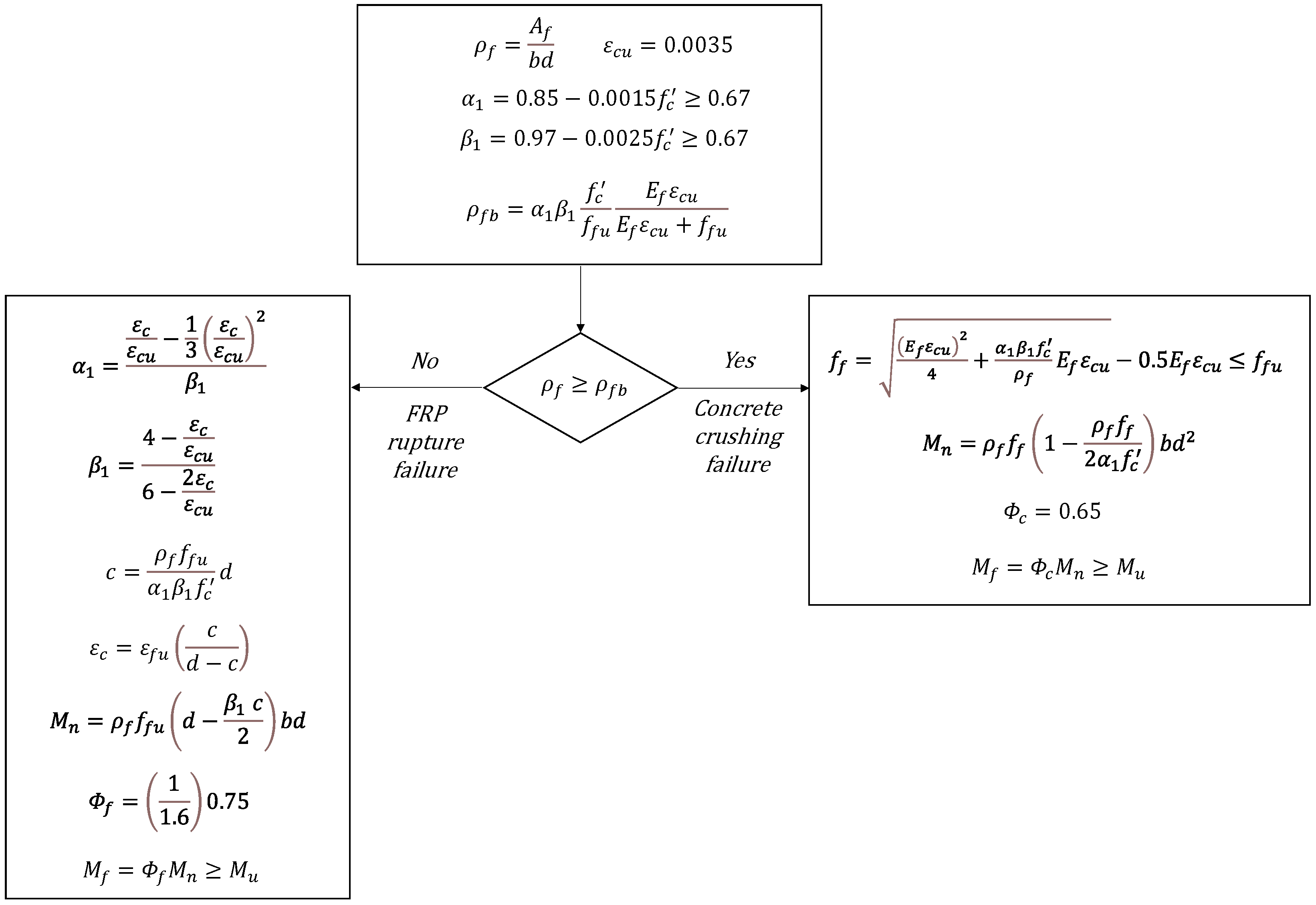
2. Provisions of CSA for Flexural Design of FRP-RC Beams

The flowchart in Figure 1 illustrates the flexural strength provisions as per CSA S806-12. It is noted that the flexural equations for FRP-RC beams are initially divided into two categories depending on the mode of failure, namely concrete crushing versus FRP rupture. The FRP bars differ from steel bars since FRP behaves linearly till rupture without yielding, whereas steel yields. This is why the failure of concrete sections due to rupture of the FRP bars in FRP-RC beams is known to be brittle (or at least less ductile) compared to the ductile failure of steel-RC beams due to yielding of steel bars. As for concrete crushing, the failure is clearly brittle regardless of the type of reinforcement. Earlier version of CSA S806 in 2002 [3] did not allow FRP rupture in the design of FRP-RC beams. This is in line with the previously mentioned fact that FRP rupture was deemed to be more brittle than the concrete crushing, although neither one is ductile.
The variables in Figure 1 are defined at the end of the manuscript (in the Nomenclature section). It is noted that in the case of the FRP rupture mode of failure, ε c (in Figure 1) is the compressive strain in the extreme fibers of the concrete section; this is less than ε c u , which is the ultimate compressive strain of concrete. The coefficients of α 1 and β 1 (in Figure 1) are related to the maximum stress and depth of equivalent rectangular stress block, respectively. It is noticed that the formulae for α 1 and β 1 depend on the failure mode under study.
In the recent version (CSA S806-12), the FRP rupture mode of failure is permitted, provided that the factored strength is 1.6-fold greater than the ultimate load, as follows:
M f 1.6 M u
By substituting the flexural strength equation from Figure 1 in Equation (1), the following is reached:
Φ f ρ f f f u d β 1   c 2 b d 1.6 M u
Which yields the following:
Φ f 1.6 ρ f f f u d β 1   c 2 b d M u
This means that the strength-reduction factor Φ f = 0.75 is actually reduced to Φ f = 1 1.6 0.75 = 0.47 . This smaller reduction factor is justified since the FRP rupture is a brittle mode of failure. It is also worth mentioning that the strength-reduction factor Φ c in the previous version of CSA S806 in 2002 was equal to 0.6; however, in the current version, the value of Φ c has been increased to 0.65. In brief, the CSA S806 code for FRP-RC flexural strength design has been changed over time in two aspects. Firstly, the FRP rupture mode is currently allowed due to a very conservative factor for Φ f . Secondly, the concrete strength-reduction factor, Φ c , is increased slightly. Essentially, the reliability of flexural strength provisions in CSA is adjusted by the two partial reduction factors Φ c and Φ f , which are applied to the material strength of concrete and FRP, respectively.

3. Methodology of Reliability-Based Evaluation

The details of the reliability method for the evaluation of flexural strength equations of FRP-RC beams based on CSA S806 are described in the following sections.

3.1. Statistical Characteristics of Uncertain Variables

The variables that appear in the formulae in Figure 1 are subjected to various levels of uncertainty; therefore, their probabilistic properties need to be taken into account. The uncertain variables include both strength variables as well as load variables as listed in Table 1, along with their statistical characteristics. The probabilistic distribution types of variables and the corresponding statistical characteristics (i.e., mean, bias, standard deviation, and COV) are based on the published research [12,18,19,20,21,22,23,24,25,26], and references are listed in Table 1 (in “Ref.” column) for each variable.
The strength variables are related to either geometrical dimensions or material properties. The dimensional variables in this study consist of the beam width b , effective depth of beam d , and cross-sectional area of longitudinal reinforcement (i.e., FRP bars) A f . The strength variables are as follows: the compressive strength of the concrete f c , and the tensile strength and elastic modulus of FRP bars, f f u and E f .
As listed in Table 1, the concrete compressive strength f c follows a normal distribution with a constant coefficient of variation (COV) of 0.101, and the bias is taken from the equation expressed in Table 1, as recommended by [19]. As for FRP’s material properties ( f f u and E f ), the published data for FRP bars [24,25] suggest a normal distribution for f f u and E f , with the mean and standard deviation (SD) as specified in Table 1. The beam dimensions (b and d) follow normal distribution, while the FRP cross-sectional area A f is taken as a lognormal distribution with a small COV, implying the use of standard quality control measures [12,18]. The load variables considered herein are dead, live, snow, and wind loads. The dead load is assumed to be normally distributed with a smaller COV, while the live, snow, and wind loads have higher variability. As recommended by the literature on the code calibration [26], the live and wind loads typically follow Gumbel distribution, whereas snow is assumed to be a lognormal distribution, with the statistical properties specified in Table 1.
Another group of uncertain strength variables refers to the uncertainty associated with the model itself, namely the so-called professional factor P f . The model uncertainty variable, P f , is determined by the ratio of the experimental flexural strength ( M e x p ) to the flexural strength, predicted using the code provisions ( M p r e d ). Thereby, experimental data on flexural strength of FRP-RC beams are required in order to evaluate P f . In doing so, a large experimental database is collected in this paper from the wider literature. For each beam in the test database, P f values for flexural strength provisions of CSA S806 are determined.
In total, 303 FRP-RC beams that failed in flexural mode are assembled from the published papers [27,28,29,30,31,32,33,34,35,36,37,38,39,40,41,42,43,44,45,46,47,48,49,50,51,52,53,54,55,56,57,58,59,60,61,62,63,64,65,66,67,68,69,70,71,72,73,74]: The type of fibers in the database is mainly glass, but other types of fibers are also available, including carbon in 12% of the specimens, and aramid in 5% of the database. The type of FRP bar is taken into account during further examination of the mechanical properties, including Ef and ffu (i.e., the elastic modulus and the ultimate tensile strength, respectively). In this database, there are 211 beams with concrete crushing mode of failure, 81 beams with FRP rupture, and 11 beams with balanced failure. The statistics of the experimental database are summarized in Table 2. All the beams are longitudinally reinforced with only FRP bars, and have a shear span-to-depth ratio greater than 2.5. Also, the tested beams are prismatic, simply supported, and three-point- or four-point-loaded.
Three primary load combinations are selected with the load factors as specified in CSA S806-12 for FRP-RC members, including 1.25D + 1.5L, 1.25D + 1.5S, and 1.25D + 1.4W, where the dead load is present as a permanent load alongside one principal load (i.e., live, snow, or wind loads), which are the most common loading types applied to the buildings. These load types have different probabilistic properties (see Table 1); thus, this study can provide insight on how the reliability index may vary under different loading scenarios. The seismic loads are, however, excluded in the current paper, leaving room for future research.

3.2. Limit State Function

In the limit state design, the idea is that the resistance should not be less than the applied load. The difference between the resistance variable R and the load variable Q—specifically, G = R Q —is expressed as the limit state function, indicating the border between safe and unsafe design. The design criteria should provide an appropriate distance from this border, giving the required level of safety. The following is the general format for the limit state function of the present study:
G = P f M p r e d M L o a d
where P f is the model uncertainty associated with M p r e d . It should be noted that M p r e d may refer to the flexural strength equation M n in Figure 1, depending on the failure mode under study. M L o a d is the unfactored moment due to all the loads acting on the beam according to a specific load combination. For instance, M L o a d in the case of a load combination of 1.25D + 1.5L is equal to M L o a d = M D + M L , in which M D and M L are the unfactored moments due to dead and live loads, respectively. The nominal values of M D and M L for each beam in the design space are determined on the basis of an assumed value for the ratio of the live load to the total load, and also by considering that the factored moment (i.e., Φ M n ) should be equal to the factored loads to arrive at a safe design. The procedure is illustrated in the flowchart in Figure 2. Once the nominal values for all variables involved in the problem are obtained, their statistical parameters are extracted from Table 1.

3.3. Method of Reliability Analysis

The reliability method is employed using Equation (4) to calculate the reliability index β , which is a measure of the failure probability, as follows:
P f a i l u r e = G < 0 f x 1 ,   x 2 ,   ,   x n   d x 1   d x 2 d x n
P f a i l u r e = φ β = 1 φ β
where f x 1 ,   x 2 ,   ,   x n is the joint probabilistic distribution function of the input variables, and φ is the cumulative distribution function of the standard normal variable. The reliability index β is, indeed, the shortest distance from the origin to the limit state function at the design point (i.e., the most probable failure point) in the standard normal variable space. In order to determine β , an optimization approach based on iteration is needed. A larger β corresponds to the smaller probability of failure, P f a i l u r e . For instance, the failure probabilities corresponding to β = 3.5, 3.8, and 4 are as follows, respectively: 2.3263 × 10⁻⁴, 7.2348 × 10⁻⁵, and 3.1671 × 10⁻⁵. A well-known technique for calculating β is FORM [75]. Among the available algorithms for FORM, the present paper is based on iHLRF, which was introduced [76] as an improved version of HLRF [75]. The detailed explanation on the improved HLRF algorithm is given as follows:
  • Problem statement: The design point u * is to be determined in the standard normal space by minimizing u subject to the limit state equation g X u = 0 . In a mathematical form, we have the following:
    min u u   s u b j e c t   t o   g X u = 0
    Thereby, the reliability index is computed as β = u * .
  • Transformation to standard normal space: Each uncertain parameter X i is mapped to a standard normal random variable U i through a Jacobian J, such that x = x ( u ) and u = u ( x ) . Later on, all computations are performed in the standard normal u space, while the limit space function is expressed in terms of x.
  • Initialization: An initial guess for the design point, u ( 0 ) , is chosen, for instance, u = 0 (i.e., the mean in standard normal space), or the Rosenblatt transform of the mean x = u . Then, x ( 0 ) = x ( u ( 0 ) ) , which leads us to evaluate the limit state function g ( x ( 0 ) ) and its gradient in the original space x g ( x ( 0 ) ) .
  • Gradient transformation: At iteration k , the gradient x g ( x ( k ) ) is calculated and transformed to the u space using the following formula:
    u g x k = J x k T x g x k
    where J x k = u x x k is the Jacobian of the transformation.
  • Compute search direction: The gradient in u space is normalized as follows:
    α ( k ) = u g x k u g x k
    Let β ( k ) = ( α ( k ) ) T u ( k ) . Then, the classical HLRF update direction is as follows:
    Δ u ( k ) = g x k g x k
  • Improved step via line search: A line search (or step size reduction) is conducted to ensure stable convergence. First, let λ ( k ) = 1 . Then, a merit function (e.g., g ( x k + Δ x ( λ ) ) or the norm of its gradient) at the trial point is evaluated:
    u t r i a l = u k + λ k Δ u k
    If convergence improves (e.g., the absolute value of g decreases), λ k is accepted. Otherwise, λ k is decreased (e.g., by halving), and this step is repeated. Once a suitable λ k is found, the update is performed as follows:
    u k + 1 = u k + λ k Δ u k
  • Map back to the original space: The updated values, x k + 1 = x ( u k + 1 ) , are computed. Furthermore, g ( x k + 1 ) and x g x k + 1 are evaluated.
  • Convergence check: It is checked whether any of the following termination criteria are met:
    g x k + 1 is below a threshold (i.e., the limit state is nearly zero).
    u k + 1 u k is sufficiently small.
    The change in the reliability index β k or u k is very little between successive iterations.
    If it is not converged, then set k k + 1 and repeat from step 4.
  • Final results: Once convergence is achieved, u k is the approximate design point in the standard normal space. Thereby, the reliability index is determined as β u k . Transforming back to the original space yields x * = x ( u * ) , which is the design point in the x space.
It is noted that there are other classical techniques for calculating the reliability index, such as the first-order second-moment method (FOSM). However, FOSM is less accurate compared to FORM in terms of the nonlinear function of the limit state, although it is simpler in application than FORM. There are also simulation approaches to deal with the failure probability, such as the Monte Carlo simulation technique, which might be more useful when dealing with a system (i.e., many interconnected limit states).

3.4. Design Space

The objective of the design space is to consider all possible scenarios for the flexural design of FRP-RC beams according to the regulations of the CSA code [73]. Thus, the design space contains a large number of virtual beams theoretically designed based on the specific code. Then, the reliability index β is calculated for each beam in the design space, and the average of all values of β is considered as the final reliability index for the design space (see Figure 2).
In the current paper, the design space is built using four nominal values for each variable, as follows. For variables b , d , f c , and L/(D + L), four values with equal intervals in the range of 200–1000 mm, 200–1000 mm, 20–60 MPa, and 0.3–0.7, respectively, are taken. For f f u , four values are selected as reported in Table 1. In the case of ρ f / ρ f b , four values in the range of 0.001–0.999 for FRP rupture mode and four values in the range of 1–2 for concrete crushing mode are chosen. Using the above-mentioned values, the total number of beams considered in the design space arrives at 46 = 4096 virtual beams for each failure mode, giving a total of 8192 beams for both modes. In this way, it is assured that all possible design cases are taken into account. This design space is larger than the previous works examined, showing 40 beams [10], 81 beams [11], and 4000 beams [9] for both failure modes.

4. Target Reliability Index

For the reliability-based calibration of design equations, it is necessary to define a value for the target reliability index, β t , which is the allowable probability of failure. In general, the target reliability index is determined based on failure consequences and the costs due to an increased level of safety [77,78]. Concerning FRP-RC beams, one major concern is related to the brittle nature of FRP bars, suggesting an increase in the target reliability index [79]. This means that a target reliability index higher than 3.5, which is used mostly in the ordinary steel-reinforced concrete codes, is expected. He and Qiu [9] considered β t = 3.5 and 4.0 for concrete crushing and FRP rupture, respectively. This is similar to the target reliability index suggested by [15]. On the other hand, Shield [10] and Zadeh [12] proposed β t = 3.5 for both failure modes. According to Zadeh [12], the FRP rupture develops ductility similar to the concrete crushing in FRP-RC beams, which is also equivalent to the ductility of steel-RC at the time of failure, concluding that the FRP rupture is expected not to be more brittle than the concrete crushing. Thereby, Zadeh [12] proposed β t = 3.5 for both failure modes, which is also equal to the one taken in ACI 318 [80] for steel-reinforced concrete. Other researchers working on flexural strength of FRP-RC beams have also used target reliability indexes of 3.5 [16] and 3.7 [17]. On the other hand, Eurocode [81] and ISO 2394 [82] proposed β t = 3.8 for a 50-year period in the case of the ultimate limit state. It is clear that there is no general agreement on the value of β t . It should be emphasized that it is not in the scope of the present paper to suggest a specific value for the target reliability index. Instead, in the current paper, a variety of target reliability indexes for both failure modes (i.e., FRP rupture and concrete crushing) are taken into account. Thereby, the results herein are presented for not only a single value of β t , but also for a range of values including β t = 3.5 , 3.8, and 4.0. Thus, a designer may take the suitable strength-reduction factor as suggested in the current paper on the basis of the desired target reliability index. Alternatively, the current paper enables the designers to choose different values for β t , depending on the failure mode under study.

5. Results and Discussion

5.1. The Safety Level of the Existing Code

The results of our reliability analysis are presented in Table 3 for each of the two failure modes. The previous version of CSA is also studied in addition to the current version. The difference between the two versions of CSA lies in the strength-reduction factors Φ c and Φ f , as explained previously. Thereby, the values of β for four states are listed in Table 3. The mean and standard deviation of P f values are presented in Table 3 for each failure mode by assuming that P f follows a lognormal distribution of probability since its values are non-zero. As mentioned earlier, β as reported in Table 3 refers to the mean of β values calculated for 4096 beams belonging to the design space for each failure mode.
The first point, which can be seen in Table 3, is that the reliability indices for the two modes of failure are not the same, but their difference is more than 1 unit in terms of β value. Furthermore, the reliability of concrete crushing in the previous CSA was higher than that for FRP rupture. However, this situation is inverted in the latest CSA. Looking at state 3 in Table 3, the reliability index is pretty low (i.e., 2.9). This is because in the CSA S806-02, the FRP rupture was not permitted at all; therefore, there has been no reliability concern for this particular mode. As for the current version of CSA, the reliability index for FRP rupture reaches a very high value (i.e., 4.895) that is overly conservative. It is noted from Figure 1 that CSA S806-12 utilizes a factor of 1.6 for the FRP rupture, which is, indeed, the source of conservatism for this problem. It is therefore suggested to use a smaller factor than 1.6 as a revision to the current code. On the other hand, the reliability level for concrete crushing in CSA S806-12 seems to be acceptable, and it is less than that in CSA S806-02, since Φ c has increased from 0.6 in CSA S806-02 to 0.65 in CSA S806-12. Comparison between States 1 and 2 in Table 3 shows that the current version of CSA has no consistency in the reliability of the two modes of failure in FRP-RC beams, leaving room for further improvement.

5.2. Sensitivity Analysis

The effects of variations in the nominal values of different parameters on the reliability index of the current provisions of CSA S806-12 are shown in Figure 3. The results are presented separately for two failure modes (concrete crushing and FRP rupture). According to Figure 3a, the reliability index is affected by the varying values of the effective depth of FRP-RC beams, especially when the values of d are small, leading to lower values of β . Furthermore, the change in β versus varying values of d is more pronounced for concrete crushing as compared to the FRP rupture mode. Concerning the compressive strength of concrete, Figure 3b illustrates that f c has an effective impact on the values of β only when concrete crushing is the governing failure mode. This is expected since the FRP rupture mode is controlled by the FRP tensile failure rather than concrete strength. It can be seen in Figure 3b that by increasing the nominal strength of concrete, the reliability index is reduced. This is because the bias for concrete strengths of 20, 40, and 60 MPa is equal to 1.43, 1.18, and 1.15, respectively, in accordance with Table 1. As a result of such changes in the bias, β decreases with increases in f c . The sensitivity analysis is also conducted for varying values of the tensile strength of FRP bars, given as f f u . It can be observed in Figure 3c that f f u impacts β only when the governing mode is the FRP rupture, as expected. Moreover, the variation in β is consistent with the variation in the standard deviation (SD) of f f u (see Table 3).

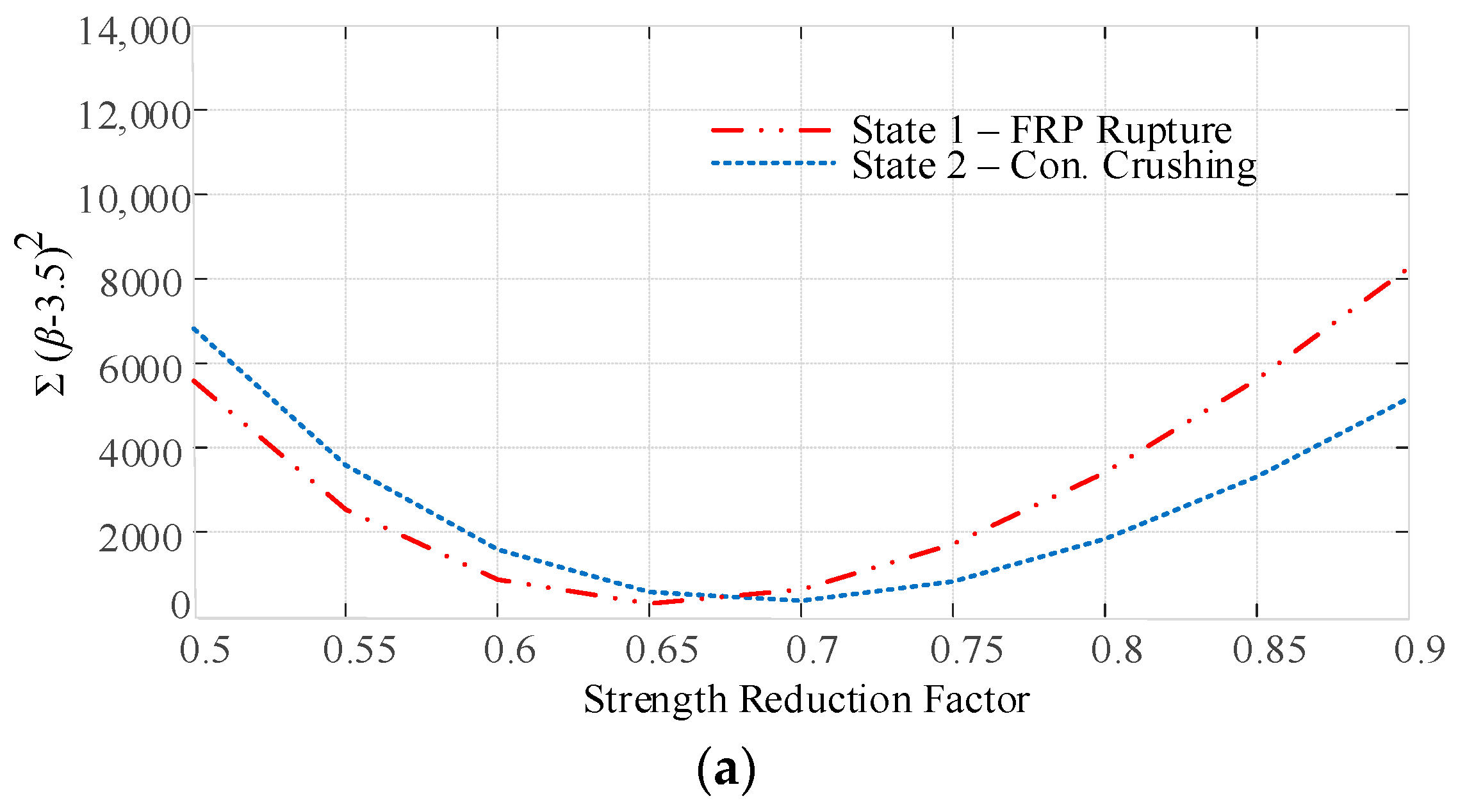
5.3. Reliability-Based Calibration of Strength-Reduction Factors

The above-mentioned discussion made it clear that the current provisions of CSA need to be improved in terms of reliability. In the present paper, it is assumed that the load factors considered in the CSA code are sufficient; therefore, the calibration is applied to strength models by tuning the strength-reduction factors to achieve the target reliability index.
In order to choose the proper value for the strength-reduction factor, the value of i = 1 N β i β t 2 is calculated, where β i refers to the reliability index determined for the ith beam in the design space which contains N beams in total, and β t is the selected target reliability index. In fact, i = 1 N β i β t 2 is a measure of closeness to the target reliability index for a series of beams, as suggested by E.4.2.6 section in ISO 2394 [78]. The results are depicted in Figure 4 for three values of β t = 3.5 , 3.8, and 4 and for a range of Φ c for concrete crushing and Φ f for FRP rupture. The final Φ c and Φ f values correspond to the minimum point of the curves shown in Figure 4. For instance, when the target reliability index of 3.8 is of concern, Φ c  = 0.65 and Φ f  = 0.6 are derived for CSA S806-12, and for concrete crushing and FRP rupture, respectively, according to Figure 4.
Figure 5 illustrates the variation in the reliability index β with respect to the strength-reduction factor (either Φ c or Φ f depending on the failure mode under study). The final Φ values, which are rounded to 0.05 digits, are summarized in Table 4 for three target reliability indexes. This table helps designers to choose the Φ factors corresponding to the desired level of reliability when using the CSA S806-12 provisions. The final outcome of the current study in the context of the reliability-based calibration of flexural strength provisions of CSA is a set of strength-reduction factors. For practical design, once a target reliability index (i.e., 3.5, 3.8 or 4) is chosen by the designer/client, the suitable strength-reduction factors ( Φ c and Φ f ) are selected from Figure 5 (or the rounded values from Table 4) for the failure mode under study (i.e., concrete crushing or FRP rupture). These values, then, are multiplied by the nominal flexural strength calculated from the current provisions of CSA S806-2 as listed in Figure 1.
The current version of CSA employs Φ c  = 0.65 and Φ f  = 0.75, and these values are kept unchanged throughout the whole code. Thereby, modification of Φ -values for flexural strength provision may affect the reliability of other parts in the code. To this end, the current Φ -values of CSA S806-12 are not altered, but instead, an m factor is defined as the ratio of calibrated Φ to the current Φ , which is then multiplied by the nominal flexural strength. To exemplify, for β t = 3.8, m values are equal to 0.65/0.65 = 1 and 0.60/0.75 = 0.8 for concrete crushing and FRP rupture, respectively, as listed in Table 5. Thereby, the CSA equations are calibrated by m, as follows:
m M f M u
As for m = 0.8 in the case of FRP rupture, we achieve the following:
M f 1 0.8 M u
Table 5. Proposed coefficient m for CSA S806-12 (βt = 3.8).
State No.Failure Mode Φ c Φ f mβ
Mean
11FRP Rupture0.650.750.83.872
12Concrete Crushing0.650.751.03.726
The inverse of 0.8 yields 1.25 as opposed to the current code, which has a similar factor of 1.6 (see Figure 1). In other words, the current provisions of CSA for the flexural strength of FRP-RC beams with the FRP rupture mode of failure are very conservative; therefore, the present paper suggests replacing 1.6 with 1.25 to meet the target reliability of 3.8. This is performed by introducing m = 0.8 for the FRP rupture mode (Equation (13)), which is the only change that is suggested in order for the current provisions of CSA S806-12 to meet β t = 3.8 , while Φ c and Φ f are kept the same as the existing code (Table 5). For other values of target reliability indices, a similar approach can be conducted.

5.4. The Probabilistic Assessment of ρ f / ρ f b

It should be noticed that the code-based relation for ρ f b (Figure 1) is not deterministic in turn due to some assumptions in modeling and the uncertainty associated with the involved parameters. Thus, ρ f b itself should be treated as an uncertain variable. In light of this, Table 6 provides the ratio of ρ f / ρ f b (i.e., the ratio of existing longitudinal reinforcement to the balanced value) for the experimental data collected in this paper. The information in Table 6 is presented separately for the FRP-RC beams which failed in concrete crushing (211 specimens), FRP rupture (81 specimens), and the balanced failure (11 specimens). Essentially, ρ f / ρ f b should be less than 1 for FRP rupture, equal to 1 for balanced failure, and greater than 1 for concrete crushing failure. However, with reference to Table 6, concrete crushing in some beam specimens is observed at ρ f / ρ f b = 0.6. Likewise, FRP rupture is observed at ρ f / ρ f b = 3. For the balanced state, the experimental values for ρ f / ρ f b are in the range of 0.8–1.7 with a mean of 1.34, according to Table 6. All these findings reveal that there are uncertainties inherent in the CSA formula for ρ f / ρ f b .
In order to take into account the uncertain nature of ρ f b , 1000 probabilistic events were generated for A f , f c , f f u , and E f on the basis of their statistical characteristics listed in Table 1, and the outcomes are depicted in Figure 6. As seen in Figure 6, when ρ f / ρ f b < 0.6, the FRP rupture occurs; similarly, when ρ f / ρ f b > 1.4, the concrete crushing happens. However, when 0.6 < ρ f / ρ f b < 1.4, the situation is different in the sense that when 0.6 < ρ f / ρ f b < 1.0, the beams are theoretically expected to fail in FRP rupture mode, but there are some beams which actually fail in concrete crushing. Once the ratio becomes closer to 1, the number of beams with concrete crushing increases so that at ρ f / ρ f b = 1, there is almost 50% FRP rupture versus 50% concrete crushing. As ρ f / ρ f b increases from 1 to 1.4, the number of beams with FRP rupture decreases. It is obvious that the occurrence probability of one failure mode is complementary to that of the other mode; this can be seen from the curves in Figure 6 for concrete crushing versus FRP rupture. Thus, there is a transition region ( ρ f b < ρ f < 1.4 ρ f b ) where both concrete crushing and FRP rupture are possible but with different probabilities of occurrence. In other words, in the transition region, the reliability index of either FRP rupture or concrete crushing is likely to take place. This may raise concerns if the reliability indices provided by the design code are different for the two failure modes, leading to either conservatism or unsafety. This is actually the case for the current provisions of CSA S806-02, as stated earlier (see States 1 and 2 in Table 3), which include very different reliability indices for concrete crushing versus FRP rupture. On the other hand, the present paper is aimed at calibrating the CSA design equations to arrive at the same reliability index for both failure modes, as presented by States 11 and 12 in Table 5. Thus, the modifications proposed in this paper offer consistent reliability for both failure modes over the whole range of ρ f / ρ f b .

5.5. Evaluation of Reliability of Existing Code Under Different Load Combinations

Unlike most of the existing research in the field which has dealt with the basic load combination of dead and live loads with load factors, as per a specific design code, the current paper is aimed at extending the reliability assessment to other load combinations containing wind and snow loads. Further study in this field is in high demand since the uncertainty behind different load types is clearly different. It is noted that for CSA S806, the load factors used for wind and snow loads are different from those for dead and live loads. For instance, the wind load is multiplied by 1.4, whereas the live load is multiplied by 1.5 and the dead load by 1.25 in the load combinations. This is common in code-based structural design dealing with the ultimate limit state approach, although the values of the load factors may be different among various design codes of practice. This highlights the fact that wind and snow loads are not treated as live or dead loads in design codes, but they are considered as separate variables. Furthermore, the difference in load factors is related to the different levels of uncertainty and risk acceptance associated with each load type. Wind and snow intensities follow specific statistical patterns (e.g., Gumbel probability distribution for wind versus lognormal for snow, as seen in Table 1) which are indeed different from those for typical occupancy-related live load or permanent dead load. The probabilistic characteristics (i.e., mean, bias, standard deviation, and COV) for each load type are listed in Table 1, as mentioned earlier.
To this end, the safety levels of flexural strength provisions of CSA S806-12 for both failure modes with respect to various load ratios in different load combinations of dead, live, snow, and wind are investigated; these are shown in Figure 7. The load ratio in Figure 7a is the ratio of the live load to the total load corresponding to the load combination of 1.25D + 1.5L. Similarly, Figure 7b corresponds to the ratio of snow load to the total load using a load combination of 1.25D + 1.5S, and Figure 7c is the ratio of the wind load to the total load with a load combination of 1.25D + 1.4W, as specified in CSA S806-12.
It is clear from Figure 7 that in the current CSA code, the reliability of FRP rupture is totally different to that of concrete crushing in all values of load ratios and for all of the load combinations under study. The following can be drawn from Figure 7:
  • The reliability index for the existing equations of CSA S806-12 for FRP rupture varies from 5.07 to 4.4 at L/(L + D) = 0.3 and 0.9, respectively. For concrete crushing, β changes from 3.8 to 3.56 at L/(L + D) = 0.4 and 0.9, respectively. For snow loads, β in the case of FRP rupture alters from 5.2 to 4.6 at S/(S + D) = 0.3 and 0.9, respectively, while for concrete crushing, the changes are in the range of 4–3.8 for S/(S + D) = 0.4–0.9. As for wind loads, the reliability index shows a large decrease from 5 to 3.73 when the load ratio, W/(W + D), increases from 0.2 to 0.9 in the case of FRP rupture, whereas for concrete crushing, β = 3.7–3.1 corresponds to the load ratios of 0.3–0.9.
  • When considering the two failure modes, it is evident (Figure 7) that the variation in β with respect to varying values of load ratios is larger (in order of 2–3 times) for FRP rupture compared to that for concrete crushing. In other words, the reliability of FRP rupture mode of failure is more sensitive to the load ratios in all load combinations considered herein, as compared to the case of concrete crushing.
  • When looking at different load combinations, it is observed that change in β due to varying values of load ratios is largest for wind loads as compared to live or snow loads. This is true for each of the failure modes.
Considering the highly random nature inherent in wind and seismic actions, their representation in design should be based on region-specific codes to account for extensive statistical studies, regional conditions, and calibration of load factors towards a desired level of structural reliability. For this reason, the current paper employs the wind load factor as per CSA S806-12 to ensure that our reliability analysis conducted herein is consistent with the codified treatment of wind actions. However, a more detailed reliability assessment must involve the structural system under study in addition to the wind load actions since the properties of the lateral load-resisting system, which is the so-called system level, need to be taken into account when creating a thorough forecast of the problem in hand. At the system level, various structural components (rather than a single component) may contribute to the loads being carried in parallel and/or in series with multimode failures. Reliability analysis at the system level is, however, beyond the objective of this study.

5.6. Relaibility-Based Calibration of Design Provisions for Different Load Combinations

Figure 8 demonstrates the results after the modifications proposed in the present study (i.e., States 11 and 12 in Table 5) are applied to the regulations of the current CSA code with a target reliability index of 3.8. For other target reliability indexes, the results are similar. In accordance with Figure 8, it is concluded that in the reliability-based calibrated provisions, the reliability index of concrete crushing is close to that of FRP rupture in all load ratios, especially in the most common range of 0.3–0.7 and for all three load combinations considered in this study, endorsing a successful calibration procedure. It is noted that all of the curves in Figure 8 are derived based on the same values for strength-reduction factors, which are the ones proposed in the current paper. Although the initial calibration was conducted for the basic load combination of dead and live loads, it seems that this suffices for snow loads as well. However, for the wind load, the situation differs due to the large variation in the reliability index across the load ratios, even in the most common range of 0.3–0.7. This is because the coefficient of variation for the wind load is higher than that for the other load types (see Table 1). The reliability assessment under various load combinations can highlight a potential need to revise the current code procedure, which takes a single strength-reduction factor for all types of the loads, especially when the load with a higher variability (e.g., wind load) is of concern, or a different target reliability index is expected. Nonetheless, the common approach to code calibration tends to consider the same reduction factors for all load combinations; thus, it is not practical to assign different reduction factors in the case of wind load combination. On the other hand, wind loading, which is lateral load acting on the framed structure, is resisted not only by a single structural component, but also by a simultaneous system of elements. Thereby, a system-based reliability approach may be more suitable to explain the lateral loadings such as wind and earthquake. In addition, the target reliability index under lateral loads may be considered to be less than the index given under the gravity loads due to less-frequent occurrence and some damage allowance. These issues need further investigation in the future.
Additionally, Figure 9a,b indicate the variation in the reliability index for FRP rupture and concrete crushing, respectively, in terms of the various load ratios in the three load combinations considered herein. It is noted that the results shown in Figure 9 correspond to the modifications proposed in this paper, as shown in Table 5. According to Figure 9, the target reliability index could be achieved with reasonable accuracy for both failure modes within the most used range of 0.3–0.7 for load ratios, especially for load combinations related to live and snow loads, and, to a lesser extent, for wind loads, as explained earlier.
Despite the extensive study conducted herein, certain limitations are acknowledged, as follows. While the experimental database used here is the largest one so far, new experiments regarding various FRP types and large-scale beams may be included in reliability analysis if such test data become available in the future. The flexural failure mode is central to the current work, excluding bond failure, shear failure, and multi-mode failures. The current work is conducted at a single component level rather than at a system level, which incorporates several structural members resisting against the applied loads, although the latter is important when dealing with seismic loads acting on a frame.

6. Conclusions

In this paper, the reliability of flexural strength provisions for the latest version of CSA S806 for FRP-RC beams is investigated by accounting for uncertainties due to material strength, geometrical characteristics, and different load types. In addition, the uncertainty inherent in the flexural model is evaluated by the experimental database assembled from the literature. Both failure modes of FRP rupture and concrete crushing are addressed in detail. The paper incorporates wind and snow loads separately from live loads to reflect the differences existing in the uncertainty levels, probabilistic characteristics, and code-based load factors associated with each load type, as per CSA S806-12. Consequently, the required modifications to the current provisions of CSA are proposed to achieve the target reliability index. The main conclusions are given as follows:
(1)
Reliability analysis of the flexural strength provisions for FRP-RC beams based on the current version of CSA S806 revealed that there is a remarkable difference in the reliability indices between the two common failure modes, namely β = 4.895 for FRP rupture versus β = 3.726 for concrete crushing. This difference is observed in the combinations of dead plus live, wind, and snow loads, with the corresponding load factors provided as per CSA and over a wide range of load ratios. The main source of conservatism accompanied by the FRP rupture mode of flexural failure is related to the incorporation of a smaller strength-reduction factor in the current CSA code when considering the FRP rupture mode of failure.
(2)
The uncertainty associated with the parameters involved in the formula for ρ f b revealed that when 0.6 < ρ f / ρ f b < 1.4, the occurrence of both failure modes (namely, concrete crushing and FRP rupture) are possible but with different levels of probability, such that at ρ f / ρ f b = 1, almost half of the total number of failed beams is the FRP rupture type, and the other half is the concrete crushing mode. This highlights the need to provide similar reliability indexes for the two failure modes, particularly in the transition range of 0.6 < ρ f / ρ f b < 1.4 so as to achieve the target reliability index regardless of which failure type may take place.
(3)
Reliability-based calibration is conducted to provide a consistent reliability index for both failure modes and for various target reliability indices of 3.5, 3.8, and 4. As a result, and in order to arrive at β t = 3.8, it is proposed to modify the current provisions by introducing an additional reduction factor equal to 0.8, which is multiplied by the nominal flexural capacity in the case of the FRP rupture mode of failure, while the strength-reduction factors (i.e., Φ c = 0.65 and Φ f = 0.75) currently existing in the CSA code are kept unchanged. The nominal flexural strength provision of the current CSA code for the concrete crushing mode of failure is deemed to be sufficient. A similar approach can be taken for any other desired value of the target reliability index.
(4)
The reliability assessment of the current provisions of CSA under three load combinations considered herein revealed that the variation in β with respect to varying values of load ratios is larger (in order of 2 or 3 times) for FRP rupture compared to that for concrete crushing. Furthermore, it is concluded that changes in β due to varying values of load ratios are largest for wind loads compared to live or snow loads.
(5)
The reliability of the flexural strength provisions with the modifications proposed in the current paper is evaluated for three load combinations of dead plus live, snow, and wind, which contain the load increment factors given in accordance with CSA. It is concluded that the target reliability index could be achieved with a reasonable accuracy for both failure modes within a feasible range of load ratios, endorsing a successful reliability-based calibration procedure especially for load combinations related to live and snow loads, and, to a lesser extent, for wind loads.
A further step for future research would call for a system-based reliability evaluation to account for characteristics of the load-resisting structural systems with multimode failures. Also, research can be directed towards reliability analysis under earthquake conditions in addition to gravity loads. Furthermore, a comparison with the reliability of other design codes on FRP-RC beams which are available worldwide could be suggested as a future study. It is worth mentioning that there is a future research need to expand the experimental database on the flexural strength of FRP-RC beams so as to include different fiber types, especially carbon, aramid, and basalt, since the majority of the existing test data contains glass FRP bars. As for the experimental failure mode, FRP rupture and the balanced failure mode are now in the minority within the worldwide experimental data. These additional data will refine the model uncertainty evaluation, which plays a key role in reliability analysis. Other necessary test data include large-scale beam specimens rather than scaled-down beams. Reliability assessment on FRP-RC beams can be extended to account for other limit states related to shear or bond failure, as well as serviceability issues (e.g., crack width and deflection).

Author Contributions

Conceptualization, N.A. and K.N.; methodology, N.A., R.A. and K.N.; validation, N.A. and K.N.; formal analysis, N.A., R.A. and K.N.; investigation, N.A., R.A. and K.N.; writing—original draft preparation, N.A., R.A. and K.N.; writing—review and editing, N.A. and K.N.; visualization, R.A.; supervision, N.A. and K.N. All authors have read and agreed to the published version of the manuscript.

Funding

This research received no external funding.

Data Availability Statement

The data related to the analyses conducted in this paper will be made available upon reasonable request from the corresponding author.

Conflicts of Interest

The authors declare no conflicts of interest.

Nomenclature

A f Cross-sectional area of FRP bars
b Width of beam cross-section
d Effective depth of beam cross-section
c Depth of the neutral axis from the uttermost compression side of cross-section
c b Depth of neutral axis corresponding to the balance state
DDead load
E f Young’s modulus of FRP bars
f c Compressive strength of concrete
f f Tensile stress in the FRP bars
f f u Ultimate tensile strength of FRP bars
G Limit state function
LLive load
mModification factor multiplied by the nominal flexural strength
M D Unfactored moment due to dead load
MexpExperimental value for the flexural strength of tested beam
M f Factored design value of flexural strength
M L Unfactored moment due to live load
M L o a d Unfactored moment due to the total load
M n Nominal flexural strength
M p r e Prediction based on the code equation for flexural strength of tested beam
M u Factored moment due to the total load
N Total number of virtual beams in the design space
PfModel uncertainty variable (i.e., the so-called professional factor)
Q Load variable in the limit state function
R Resistance variable in the limit state function
SSnow load
WWind load
βThe reliability index
β t Target reliability index
δ Coefficient of variation (COV)
ε c u Ultimate compressive strain in concrete
ε f u Ultimate tensile strain in FRP bar
λ Bias
μ Mean value
ρ f The ratio of FRP reinforcement existing in the cross-section
ρ f b The balanced ratio of FRP reinforcement
σ Standard deviation (SD)
Φ c Strength-reduction factor for concrete crushing mode of failure
Φ f Strength-reduction factor for FRP rupture mode of failure

References

  1. ACI 440.1 R-03; Guide for the Design and Construction of Concrete Reinforced with FRP Bars. American Concrete Institute: Detroit, MI, USA, 2003.
  2. ACI 440.1R-06; Guide for the Design and Construction of Structural Concrete Reinforced with FRP Bars. American Concrete Institute: Farmington Hills, MI, USA, 2006.
  3. CAN/CSA S806-02; Design and Construction of Building Components with Fiber Reinforced Polymers. Canadian Standards Association (CSA): Rexdale, ON, Canada, 2002.
  4. CAN/CSA S806-12; Design and Construction of Building Components with Fiber Reinforced Polymers. Canadian Standards Association (CSA): Rexdale, ON, Canada, 2012.
  5. Wahrhaftig, A.D.; Rodrigues, R.B.; Carvalho, R.F.; Fortes, A.S. Strengthening reinforced concrete beams with carbon fiber laminate mounted in a u-shape for static and vibration purposes. Int. J. Civ. Eng. 2022, 20, 27–40. [Google Scholar] [CrossRef]
  6. Zeng, J.J.; Ye, Y.Y.; Liu, W.T.; Zhuge, Y.; Liu, Y.; Yue, Q.R. Behaviour of FRP spiral-confined concrete and contribution of FRP longitudinal bars in FRP-RC columns under axial compression. Eng. Struct. 2023, 281, 115747. [Google Scholar]
  7. Zeng, J.J.; Zeng, W.B.; Ye, Y.Y.; Liao, J.; Zhuge, Y.; Fan, T.H. Flexural behavior of FRP grid reinforced ultra-high-performance concrete composite plates with different types of fibers. Eng. Struct. 2022, 272, 115020. [Google Scholar]
  8. Zeng, J.J.; Hao, Z.H.; Sun, H.Q.; Zeng, W.B.; Fan, T.H.; Zhuge, Y. Durability assessment of ultra-high-performance concrete (UHPC) and FRP grid-reinforced UHPC plates under marine environments. Eng. Struct. 2025, 323, 119313. [Google Scholar]
  9. He, Z.; Qiu, F. Probabilistic assessment on flexural capacity of GFRP-reinforced concrete beams designed by guideline ACI 440.1 R-06. J. Constr. Build. Mater. 2011, 25, 1663–1670. [Google Scholar]
  10. Shield, C.K.; Galambos, T.V.; Gulbrandsen, P. On the History and Reliability of the Flexural Strength of FRP Reinforced Concrete Members in ACI 440.1 R; American Concrete Institute: Farmington Hills, MI, USA, 2011; p. 275. [Google Scholar]
  11. Ribeiro, S.E.C.; Diniz, S.M.C. Reliability-based design recommendations for FRP reinforced concrete beams. Eng. Struct. 2013, 52, 273–283. [Google Scholar]
  12. Zadeh, H.J.; Nanni, A. Reliability analysis of concrete beams internally reinforced with fiber-reinforced polymer bars. ACI Struct. J. 2013, 110, 1023–1032. [Google Scholar]
  13. Nasrollahzadeh, K.; Aghamohammadi, R. Reliability analysis of shear strength provisions for FRP-reinforced concrete beams. Eng. Struct. 2018, 176, 785–800. [Google Scholar]
  14. Shamass, R.; Abarkan, I.; Ferreira, F.P. FRP RC beams by collected test data: Comparison with design standard, parameter sensitivity, and reliability analyses. Eng. Struct. 2023, 297, 116933. [Google Scholar]
  15. Hassanzadeh, A.M.; Dehestani, M.; Nazarpour, H. Reliability analysis of flexural provisions of FRP-RC beams and sensitivity analysis based on FORM. Eng. Struct. 2023, 285, 116037. [Google Scholar]
  16. Tarawneh, A.; Alajarmeh, O.; Alawadi, R.; Amirah, H.; Alramadeen, R. Database evaluation and reliability calibration for flexural strength of hybrid FRP/steel-RC Beams. Compos. Struct. 2024, 329, 117758. [Google Scholar] [CrossRef]
  17. Sang, B.; Song, S.; Wang, A.; Liu, X. Reliability analysis and calibration for flexural design provisions of GFRP-RC beams. Structures 2024, 69, 107435. [Google Scholar]
  18. Mirza, S.A.; MacGregor, J.G. Probabilistic study of strength of reinforced concrete members. Can. J. Civ. Eng. 1982, 9, 431–448. [Google Scholar]
  19. Nowak, A.S.; Szerzsen, M.M. Calibration of design code for buildings (ACI 318): Part 1—Statistical models for resistance. ACI Struct. J. 2003, 100, 377–382. [Google Scholar]
  20. El-Sayed, A.; El-Salakawy, E.; Benmokrane, B. Shear strength of one-way concrete slabs reinforced with fiber-reinforced polymer composite bars. J. Compos. Constr. 2005, 9, 147–157. [Google Scholar]
  21. El-Sayed, A.K.; El-Salakawy, E.F.; Benmokrane, B. Shear strength of FRP reinforced concrete beams without transverse reinforcement. ACI Struct. J. 2006, 103, 235–243. [Google Scholar]
  22. Michaluk, R.; Rizkalla, S.; Tadros, G.; Benmokrane, B. Flexural behavior of one-way concrete slabs reinforced by fiber reinforced plastic reinforcement. ACI Struct. J. 1998, 95, 353–365. [Google Scholar]
  23. El-Sayed, A.K.; El-Salakawy, E.F.; Benmokrane, B. Shear capacity of high-strength concrete beams reinforced with FRP bars. ACI Struct. J. 2006, 103, 383–389. [Google Scholar]
  24. Kocaoz, S.; Samaranayake, V.A.; Nanni, A. Tensile characterization of glass FRP bars. Compos. Part B Eng. 2005, 36, 127–134. [Google Scholar]
  25. ACI 440.1R-15; Guide for the Design and Construction of Structural Concrete Reinforced with FRP Bars. American Concrete Institute: Farmington Hills, MI, USA, 2015.
  26. Nowak, A.S.; Collins, K.R. Reliability of Structures; McGraw-Hill: Boston, MA, USA, 2000. [Google Scholar]
  27. Nawy, E.G.; Neuwerth, G.E.; Phillips, C.J. Behavior of fiber glass reinforced concrete beams. J. Struct. Div. 1971, 97, 2203–2215. [Google Scholar] [CrossRef]
  28. Nawy, E.G.; Neuwerth, G.E. Fiberglass reinforced concrete slabs and beams. J. Struct. Div. 1977, 103, 421–440. [Google Scholar]
  29. Faza, S.S.; GangaRao, H.V. Bending and Bond Behavior of Concrete Beams Reinforced with Plastic Rebars. In Proceedings of the Third Bridge Engineering Conference: Papers Presented at the Third Bridge Engineering Conference, Denver, CO, USA, 10–13 March 1991. [Google Scholar]
  30. Faza, S.S. Bending and Bond Behavior and Design of Concrete Beams Reinforced with Fiber Reinforced Plastic Rebars. Diss. Abstr. Int. 1992, 53, 213. [Google Scholar]
  31. Brown, V.L.; Bartholomew, C.L. FRP reinforcing bars in reinforced concrete members. ACI Mater. J. 1993, 90, 34–39. [Google Scholar]
  32. Benmokrane, B.; Chaallal, O.; Masmoudi, R. Flexural response of concrete beams reinforced with FRP reinforcing bars. ACI Struct. J. 1996, 93, 46–55. [Google Scholar]
  33. Benmokrane, B.; Masmoudi, R. FRP C-bar as reinforcing rod for concrete structures. In Proceedings of the 2nd International Conference on Advanced Composite Materials in Bridges and Structures, ACMBS-II, Montreal, QC, Canada, 11–14 August 1996. [Google Scholar]
  34. Brown, V.L.; Bartholomew, C.L. Long-term deflections of GFRP-reinforced concrete beams. In Proceedings of the First International Conference on Composites in Infrastructure, Tucson, AZ, USA, 15–17 January 1996. [Google Scholar]
  35. Al-Salloum, Y.A.; Alsayed, S.H.; Almusallam, T.H.; Amjad, M.A. Some Design Consideration for Concrete Beams Reinforced by Glass Fiber Reinforced Plastics (GFRP) Bars. In Proceedings of the First International Conference on Composites in Infrastructure, Tucson, AZ, USA, 15–17 January 1996. [Google Scholar]
  36. Alsayed, S.H.; Al-Salloum, Y.A.; Almusallam, T.H. Performance of glass fiber reinforced plastic bars as a reinforcing material for concrete structures. Compos. Part B Eng. 2000, 31, 555–567. [Google Scholar]
  37. Vijay, P.V.; GangaRao, H.V.S. A unified limit state approach using deformability factors in concrete beams reinforced with GFRP bars. In Materials for the New Millennium; ASCE: Reston, VA, USA, 1996; pp. 657–665. [Google Scholar]
  38. Almusallam, T.H.; Al-Salloum, Y.A.; Alsayed, S.H.; Amjad, M.A. Behavior of concrete beams doubly reinforced by FRP bars. In Proceedings of the Third International Symposium on Nonmetallic (FRP) Reinforcement for Concrete Structures (FRPRCS-3); Japan Concrete In-Stitute: Sapporo, Japan, 1997; Volume 2, pp. 471–478. [Google Scholar]
  39. Cosenza, E.; Manfredi, G.; Realfonzo, R. Behavior and modeling of bond of FRP rebars to concrete. J. Compos. Constr. 1997, 1, 40–51. [Google Scholar]
  40. Sonobe, Y.; Fukuyama, H.; Okamoto, T.; Kani, N.; Kimura, K.; Kobayashi, K.; Teshigawara, M. Design guidelines of FRP reinforced concrete building structures. J. Compos. Constr. 1997, 1, 90–115. [Google Scholar]
  41. Benmokrane, B.; Theriault, M.; Masmoudi, R.; Rizkalla, S. Effect of reinforcement ratio on concrete members reinforced with FRP bars. Evol. Technol. Compet. Edge 1997, 42, 87–98. [Google Scholar]
  42. Nawy, E.G.; Neuwerth, G.E. Fiber glass as main reinforcement for concrete two-way slabs, plates and beams. In Engineering Research Bulletin; Rutgers University: New Brunswick, NJ, USA, 1976. [Google Scholar]
  43. Swamy, N.; Aburawi, M. Structural implications of using GFRP bars as concrete reinforcement. In Proceedings of the Third International Symposium on Nonmetallic (FRP) Reinforcement for Concrete Structures (FRPRCS-3), Sapporo, Japan, 14–16 October 1997; Volume 3, pp. 503–510. [Google Scholar]
  44. Duranovic, N.; Pilakoutas, K.; Waldron, P. Tests on concrete beams reinforced with glass fiber reinforced plastic bars. In Proceedings of the Third International Symposium on Nonmetallic (FRP) Reinforcement for Concrete Structures (FRPRCS-3), Sapporo, Japan, 14–16 October 1997; pp. 479–486. [Google Scholar]
  45. Gao, D.; Benmokrane, B.; Masmoudi, R. A calculating method of flexural properties of FRP-reinforced concrete beam: Part I: Crack width and deflection. In Technical Report, Department of Civil Engineering; University of Sherbrooke: Sherbrooke, QC, Canada, 1998. [Google Scholar]
  46. Grace, N.F.; Soliman, A.K.; Abdel-Sayed, G.; Saleh, K.R. Behavior and ductility of simple and continuous FRP reinforced beams. J. Compos. Constr. 1998, 2, 186–194. [Google Scholar]
  47. Theriault, M.; Benmokrane, B. Effects of FRP reinforcement ratio and concrete strength on flexural behavior of concrete beams. J. Compos. Constr. 1998, 2, 7–16. [Google Scholar]
  48. Alsayed, S.H. Flexural behavior of concrete beams reinforced with GFRP bars. Cem. Concr. Compos. 1998, 20, 1–11. [Google Scholar] [CrossRef]
  49. Pecce, M.; Manfredi, G.; Cosenza, E. Experimental Response and Code Models of GFRP RC Beams in Bending. J. Compos. Constr. 2000, 4, 182–190. [Google Scholar]
  50. Toutanji, H.A.; Saafi, M. Flexural behavior of concrete beams reinforced with glass fiber-reinforced polymer (GFRP) bars. Struct. J. 2000, 97, 712–719. [Google Scholar]
  51. Aiello, M.A.; Ombres, L. Load-deflection analysis of FRP reinforced concrete flexural members. J. Compos. Constr. 2000, 4, 164–171. [Google Scholar]
  52. Yost, J.R.; Goodspeed, C.H.; Schmeckpeper, E.R. Flexural performance of concrete beams reinforced with FRP grids. J. Compos. Constr. 2001, 5, 18–25. [Google Scholar]
  53. Thiagarajan, G. Experimental and analytical behavior of carbon fiber-based rods as flexural reinforcement. J. Compos. Constr. 2003, 7, 64–72. [Google Scholar]
  54. Rashid, M.A.; Mansur, M.A.; Paramasivam, P. Behavior of aramid fiber-reinforced polymer reinforced high strength concrete beams under bending. J. Compos. Constr. 2005, 9, 117–127. [Google Scholar]
  55. Al-Sunna, R.; Pilakoutas, K.; Waldron, P.; Al-Hadeed, T. Deflection of FRP reinforced concrete beams. In Proceedings of the 2nd FIB congress, Naples, Italy, 5 June 2006; pp. 5–8. [Google Scholar]
  56. Wang, H.; Belarbi, A. Flexural behavior of fiber-reinforced-concrete beams reinforced with FRP rebars. ACI Struct. J. 2005, 51, 895–914. [Google Scholar]
  57. Ashour, A.F. Flexural and shear capacities of concrete beams reinforced with GFRP bars. Constr. Build. Mater. 2006, 20, 1005–1015. [Google Scholar]
  58. Ashour, A.F.; Family, M. Tests of concrete flanged beams reinforced with CFRP bars. Mag. Concr. Res. 2006, 58, 627–639. [Google Scholar]
  59. Rafi, M.M.; Nadjai, A.; Ali, F.; Talamona, D. Aspects of behavior of CFRP reinforced concrete beams in bending. Constr. Build. Mater. 2008, 22, 277–285. [Google Scholar] [CrossRef]
  60. Ashour, A.F.; Habeeb, M.N. Continuous concrete beams reinforced with CFRP bars. Proc. Inst. Civ. Eng. Struct. Build. 2008, 161, 349–357. [Google Scholar] [CrossRef]
  61. Barris, C.; Torres, L.; Turon, A.; Baena, M.; Catalan, A. An experimental study of the flexural behaviour of GFRP RC beams and comparison with prediction models. Compos. Struct. 2009, 91, 286–295. [Google Scholar] [CrossRef]
  62. Shin, S.; Seo, D.; Han, B. Performance of concrete beams reinforced with GFRP bars. J. Asian Archit. Build. Eng. 2009, 8, 197–204. [Google Scholar] [CrossRef]
  63. Chitsazan, I.; Kobraei, M.; Jumaat, M.Z.; Shafigh, P. An experimental study on the flexural behaviour of FRP RC bemas and comparison of the ultimate moment capacity with ACI. J. Civ. Eng. Constr. Technol. 2010, 1, 27–42. [Google Scholar]
  64. Kalpana, V.G.; Subramanian, K. Behavior of concrete beams reinforced with GFRP bars. J. Reinf. Plast. Compos. 2011, 30, 1915–1922. [Google Scholar] [CrossRef]
  65. Issa, M.S.; Metwally, I.M.; Elzeiny, S.M. Influence of fibers on flexural behavior and ductility of concrete beams reinforced with GFRP rebars. Eng. Struct. 2011, 33, 1754–1763. [Google Scholar] [CrossRef]
  66. Getzlaf, D.D. An Investigation into the Flexural Behavior of GFRP Reinforced Concrete Beams. Ph.D. Thesis, University of Toronto, Toronto, ON, Canada, 2012. [Google Scholar]
  67. Adam, M.A.; Said, M.; Mahmoud, A.A.; Shanour, A.S. Analytical and experimental flexural behavior of concrete beams reinforced with glass fiber reinforced polymers bars. Constr. Build. Mater. 2015, 84, 354–366. [Google Scholar] [CrossRef]
  68. Lau, D.; Pam, H.J. Experimental study of hybrid FRP reinforced concrete beams. Eng. Struct. 2010, 32, 3857–3865. [Google Scholar] [CrossRef]
  69. Ascione, L.; Mancusi, G.; Spadea, S. Flexural behaviour of concrete beams reinforced with GFRP bars. Strain 2010, 46, 460–469. [Google Scholar] [CrossRef]
  70. Kassem, C.; Farghaly, A.S.; Benmokrane, B. Evaluation of flexural behavior and serviceability performance of concrete beams reinforced with FRP bars. J. Compos. Constr. 2011, 15, 682–695. [Google Scholar] [CrossRef]
  71. El-Nemr, A.; Ahmed, E.A.; Benmokrane, B. Flexural behavior and serviceability of normal and high-strength concrete beams reinforced with glass fiber-reinforced polymer bars. ACI Struct. J. 2013, 110, 1077. [Google Scholar]
  72. Goldston, M.W. Behavior of Concrete Beams Reinforced with GFRP Bars Under Static & Impact Loading. Ph.D. Thesis, University of Wollongong, Wollongong, Australia, 2016. [Google Scholar]
  73. Berry, M.; Johnson, J.; McDevitt, K. Effect of cold temperatures on the behavior and ultimate capacity of GFRP-reinforced concrete beams. Cold Reg. Sci. Technol. 2017, 136, 9–16. [Google Scholar] [CrossRef]
  74. Mohtaj Khorasani, A.M.; Esfahani, M.R.; Sabzi, J. The effect of transverse and flexural reinforcement on deflection and cracking of GFRP bar reinforced concrete beams. Compos. Part B Eng. 2019, 161, 530–546. [Google Scholar] [CrossRef]
  75. Rackwitz, R.; Fiessler, B. Structural reliability under combined random load sequences. Comput. Struct. 1978, 9, 489–494. [Google Scholar] [CrossRef]
  76. Der Kiureghian, A. First-and second-order reliability methods. In Engineering Design Reliability Handbook; Nikolaidis, E., Ghiocel, D.M., Singhal, S., Eds.; CRC Press: Boca Raton, FL, USA, 2005. [Google Scholar]
  77. Okeil, A.; Belarbi, A.; Kuchma, D. Reliability assessment of FRP-strengthened concrete bridge girders in shear. J. Compos. Constr. ASCE 2013, 17, 91–100. [Google Scholar]
  78. Szerszen, M.M.; Nowak, A.S. Calibration of Design Code for Buildings (ACI 318): Part 2: Reliability Analysis and Resistance Factors. ACI Struct. J. 2003, 100, 383–391. [Google Scholar]
  79. Aghamohammadi, R.; Nasrollahzadeh, K.; Mofidi, A.; Gosling, P. Reliability-based assessment of bond strength models for near-surface mounted FRP bars and strips to concrete. Compos. Struct. 2021, 272, 114132. [Google Scholar] [CrossRef]
  80. ACI 318–11; Building Code Requirements for Structural Concrete and Commentary. American Concrete Institute: Farmington Hills, MI, USA, 2011.
  81. Eurocode EN 1990; Fundamentals of Structural Design. CEN: Brussels, Belgium, 2001.
  82. ISO 2394; International Organization for Standardization. General Principles on Reliability of Structures: Geneva, Switzerland, 2015.
Figure 1. Flexural strength provisions of CSA S806-12 design code.
Jcs 09 00154 g001
Figure 2. Diagram of calculation of β .
Jcs 09 00154 g002
Figure 3. Sensitivity analysis results in (a) effective depth of the beam, (b) concrete strength, and (c) tensile strength of FRP bars.
Jcs 09 00154 g003aJcs 09 00154 g003b
Figure 4. Closeness to βt.
Jcs 09 00154 g004aJcs 09 00154 g004b
Figure 5. Variation in β in terms of Φ c and Φ f .
Jcs 09 00154 g005
Figure 6. Probability of occurrence of each mode in terms of ρ f / ρ f b .
Jcs 09 00154 g006
Figure 7. Reliability index for various load ratios in different load combinations (current code) including. (a) live and dead loads, (b) snow and dead loads, (c) wind and dead loads.
Jcs 09 00154 g007
Figure 8. Reliability index for various load ratios in different load combinations (modified code) including. (a) live and dead loads, (b) snow and dead loads, (c) wind and dead loads.
Jcs 09 00154 g008aJcs 09 00154 g008b
Figure 9. Reliability index compared in different load combinations for the proposed modifications of code. (a) FRP rupture, (b) concrete crushing.
Jcs 09 00154 g009
Table 1. Probabilistic characteristics of different variables.
Source of
Uncertainty
Name
(Unit)
Nominal
Value
Mean
μ
Bias
λ
SD
σ
COV
δ
Distribution
(PDF)
Ref.
Fabrication b (mm) b b + 2.286-4.826-Normal[18]
d (mm) d d − 4.826-12.70-Normal
A f (mm2) A f -1-0.003Lognormal[12]
Material f c (MPa) f c - 2.413 × 10 5 f c 3
+ 3.1743 × 10 3 f c 2
1.3543 × 10 1 f c
+ 3.0649
-0.101Normal[19]
f f u (MPa)
( E f ) (GPa)
μ 3 σ
( μ )
597
(40)
-36
(1)
-Normal [25]
(Normal) [24]
[20]
608 a
(39)
-28
(1)
-[21]
692 a
(41.3)
-19.4
(1.25)
-[22]
754 a
(420)
-19
(1)
-[21]
769
(135)
-7
(5)
-[23]
986
(134)
-50
(9)
-
1536 a
(128)
-31
(5)
-[20]
Load bDead (kN)D-1.05-0.10Normal[26]
Live (kN)L-1.00-0.18Extreme Value Type I (Gumbel)
Snow (kN)S-0.82-0.26Lognormal
Wind (kN)W-0.78-0.37Extreme Value Type I (Gumbel)
a Used in parametric study of design space. b Maximum 50-year load.
Table 2. Statistical characteristics of experimental datasets for FRP-RC beams.
ParameterConcrete Crushing
(211 Specimens)
FRP Rupture
(81 Specimens)
Balanced Failure
(11 Specimens)
Min.Max.MedianMin.Max.MedianMin.Max.Median
b (mm)90500180100500152100200152
d (mm)101404215122504253127269245
ρ f (%)0.1953.9101.1460.1191.2250.4990.2801.2600.772
f c (MPa)16.30100.5039.6019.6085.6043.0028.0076.4929.42
f f u   (MPa)5042069776586225073253915061000
E f (GPa)262004530200442912264
M e x p (kN)4.0023850.803.16200.4636.804.6082.5250.84
Table 3. Model uncertainty variable P f and reliability index β .
State No.CodeFailure ModeNumber of
Test Data
P f β
MeanCOVMean
1CSA S806-12FRP Rupture920.95418.2414.895
2Concrete Crushing2221.07019.2973.726
3CSA S806-02FRP Rupture920.95418.2412.917
4Concrete Crushing2221.07019.2974.040
Table 4. Suggested strength-reduction factor of CSA S806-12 for different values of βt.
State No.Failure Modeβt Φ c   or   Φ f β
Mean
5FRP Rupture3.50.653.533
6Concrete Crushing0.703.433
7FRP Rupture3.80.603.872
8Concrete Crushing0.653.726
9FRP Rupture4.00.603.872
10Concrete Crushing0.604.041
Table 6. Ratio of code-based ρ f / ρ f b evaluated in the experimental data.
ParameterConcrete Crushing
(211 Specimens)
FRP Rupture
(81 Specimens)
Balanced Failure
(11 Specimens)
Min.Max.MeanMin.Max.MeanMin.Max.Mean
ρ f / ρ f b 0.61213.9592.8860.2693.0840.8180.7811.6981.335
Disclaimer/Publisher’s Note: The statements, opinions and data contained in all publications are solely those of the individual author(s) and contributor(s) and not of MDPI and/or the editor(s). MDPI and/or the editor(s) disclaim responsibility for any injury to people or property resulting from any ideas, methods, instructions or products referred to in the content.

