Abstract
This research investigates the performance of glass-fiber-reinforced polymer (GFRP) composite panels under high-velocity impacts, with a focus on panels of varying radii of curvature (ROC): flat, 203 mm ROC, and 112 mm ROC. Both spherical and conical projectiles were used in the impact tests conducted using experimental and numerical approaches using an LS-DYNA solver. The results show that, as the curvature increases, the energy absorption increases for both types of projectiles. The 112 mm ROC panel demonstrated the highest ballistic limit velocity and energy absorption, outperforming both the flat and 203 mm ROC panels. Specifically, it exhibited a 22% higher ballistic limit velocity for spherical projectiles and a 17% increase for conical projectiles compared to the flat panel. The 112 mm ROC panel also absorbed the most energy, with a maximum of 36.3 J at 91 m/s for spherical impacts, resulting in extensive damage, including delamination, fiber pullout, and matrix debonding. The findings highlight the enhanced impact resistance of GFRP composite panels with higher curvature, particularly under spherical impacts.
1. Introduction
Glass-fiber-reinforced polymer (GFRP) is a composite material that has extensive applications across multiple industries owing to its exceptional mechanical properties, corrosion resistance, and high strength-to-weight ratio. In aerospace and defense sectors, GFRP has gained prominence as a vital material for both structural and non-structural applications [1,2,3].
Ballistic impact analysis plays a critical role in the design and development of materials and structures used in both the automotive and aerospace industries. This analysis involves evaluating how materials respond to high-velocity impacts. Ballistic impact analysis is essential for advancing safety, material performance, and durability in aerospace and automotive applications, especially as both industries prioritize light-weight high-strength materials and stringent safety requirements [4,5,6,7].
Performing impact analyses on curved composite panels is essential because curved structures exhibit unique stress behaviors, deformation patterns, and potential failure modes that differ significantly from flat panels. These analyses ensure that real-world curved components can withstand impact forces, maintain safety, and optimize performance in demanding applications like aerospace, defense, and automotive engineering [8,9,10]. The dynamic behavior of composite laminates has been investigated by scholars using diverse methodologies, including theoretical analysis, experimental studies, and numerical simulations, leading to numerous significant research outcomes [11,12,13,14,15,16,17].
Although GFRP panels exhibit considerable strength and low weight, they are vulnerable to multiple failure mechanisms, such as delamination, fiber breakage, fiber pullout, matrix cracking, and environmental degradation, which are typically observed in proximity to the impact region. Understanding these failure modes is critical for improving the durability, safety, and reliability of GFRP structures. At the impact location, fiber fractures and matrix cracks are more likely to appear inside the laminate. The area surrounding the impact region exhibits a diverse array of intralayer matrix cracks within the laminate, resulting from the impact of tensile, compressive, and shear forces. These cracks extend into neighboring layers, leading to delamination damage between them. The mechanical properties of the laminate will be significantly impacted by damages, including indentation, matrix cracks, and delamination. Significant research work has been conducted on the damage and failure characteristics of curved fiber-reinforced plastic (FRP) composite plates and intricate structural components when subjected to impact loads [18,19,20,21,22]. Bazle Z and John W [23] found that a new penetration equation for ballistic limit analysis (BLA) addresses limitations in classic models by incorporating the principles of the conservation of momentum and energy. It defines a more accurate projectile instantaneous velocity at the ballistic limit, improving the prediction of residual and jump velocities. The equation aligns well with the experimental data for various target materials, and this work paves the way for future theoretical models that consider the projectile and target’s material properties. Ahmad bidi [24] studied experimentally the low-velocity impact behavior on the nano polyurea reinforced on the steel curved plate and found that the addition of nano polyurea increased the energy absorption capability by 5%. Arivoli and Ramajeyathilagam [25] conducted a numerical analysis on the response of a curved nanocomposite panel subjected to low-velocity impacts. Also, parametric studies on the impact on the convex and concave sides of panels subjected to different projectiles and different thicknesses of panels have been studied.
Different projectile shapes lead to varied types of damage to materials. While spherical and blunt projectiles create broader and less penetrating damage, conical and cylindrical projectiles focus energy at a point and penetrate more deeply [26]. Jordon and Naito [27] explored the relationship between impactor nose shape and the impact resistance of GFRP targets using experimental methods. Their research revealed that the ballistic limit velocity and the energy absorption potential were considerably impacted by the configuration of the projectile’s nose. Dey et al. [28] investigated the effect of target strength on the perforation of steel plates using Weldox 460 E, 700 E, and 900 E. Their perforation tests with different projectile nose shapes revealed that the ballistic limit velocity decreases with target strength for blunt projectiles, while it increases for conical and ogival projectiles. Numerical simulations using LS-DYNA accurately modeled the perforation process, but did not replicate the decrease in ballistic limit observed with blunt projectiles. Bendarma et al. [29] studied the material behavior of Alucobond composite structures, made of Aluminum alloy AW5005 and LDPE, under ballistic impacts. The mechanical properties are characterized by strain rate and temperature dependencies, with tests conducted at various strain rates and temperatures ranging from 20 °C to 100 °C. The impact behavior is influenced by the projectile geometry, impact velocity, and thermomechanical properties of the target. The study includes original quasi-static and dynamic test results, and numerical simulations using ABAQUS provide additional insights into the dynamic behavior of the impacted structures.
Studying the impact responses of curved panels is crucial for real-world applications like aerospace, automotive, defense, and marine engineering. In aerospace engineering, it helps optimize designs for bird strikes or debris impacts on aircraft. For vehicles, it improves crash safety by understanding energy absorption in curved surfaces. In defense, it enhances armored vehicle protection against projectiles. In marine engineering, it ensures hull integrity under impact from waves or collisions. Overall, this research is vital for improving safety, structural integrity, and material efficiency in curved panel designs across various industries. The primary aim of this study is to create three distinct configurations of curved glass-fiber-reinforced polymer (GFRP) panels: flat, 203 mm radii of curvature (ROC), and 112 mm radii of curvature (ROC), as illustrated in Figure 1. This study investigates how damage evolves for each curvature configuration when impacted by spherical and conical projectiles of identical mass. By examining these variations, it provides insights into the differences in failure mechanisms between flat and curved panels under ballistic impacts. This research is particularly important, as many existing studies focus on GFRP flat plate damage and failure mechanisms, but there are a lack of comprehensive investigations into the high-velocity impact behavior of different curvatures of GFRP composites. One key area is the limited understanding of how varying curvature angles affect the distribution of impact forces and the material’s energy absorption capabilities. Additionally, there are insufficient explorations into how material properties, such as delamination and matrix cracking, change under curved geometries, influencing damage progression and failure mechanisms. The dynamic response of curved panels during high-velocity impacts, especially under complex loading conditions, also remains under-researched. Moreover, the influence of different panel configurations, such as concave and convex curvatures, on ballistic performance with various projectile types needs further investigation. Lastly, more studies are required on the ballistic performance of multi-layered curved composite panels to understand how curvature interacts with energy distribution during impact. Understanding how curvature influences structural response and damage progression is crucial for designing materials and structures subjected to impact loading.
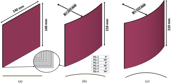
Figure 1.
Three configurations of composite laminates: (a) flat laminate, (b) 203 mm ROC laminate, and (c) 112 mm ROC laminate.
2. Experiment
2.1. Materials and Fabrication
The quality of curved laminates plays a crucial role in the outcomes of experimental tests; therefore, it is essential to fabricate uniformly shaped and high-quality laminates. Flat laminate can be prepared on a simple flat rigid surface. However, to make a curved laminate, a respective curved mold is needed. The mold for the curved laminates was made from neem wood, and it was prepared using a high-precision computer numerical control (CNC) machine. Two configurations of curvature such as 112 mm ROC and 203 mm ROC were considered. The height–length ratio of the 203 mm ROC and 112 mm ROC panels is 9.33 and 18.66, respectively. The original and schematic image of the curved mold is shown in Figure 2 and Figure 3.
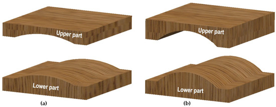
Figure 2.
Three-dimensional models of wooden mold (a) 203ROC (b) 112ROC.
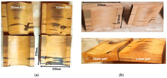
Figure 3.
Fabricated wooden mold for 112ROC and 203ROC: (a) top view, (b) iso view.
In this study, flat and curved laminates were manufactured using the vacuum bagging method as shown in Figure 4. The specimens were made using a matrix system of Araldite® LY 556 epoxy resin and Aradur HY 951 hardener (in a 100:12 weight ratio), sourced from Huntsman International (Mumbai, India), along with 200 GSM bi-directional BD woven glass fabric from Parshawa Composites (Belagavi, India). Araldite® LY 556 combined with Aradur HY 951 offers a low-viscosity solvent-free laminating system that cures at room temperature and demonstrates exceptional water resistance. Adjusting the quantity of hardener Aradur HY 951 between 10 and 12 parts allows for the customization of the system’s reactivity to align with the desired processing and curing conditions. The resin and hardener must be blended thoroughly to achieve a uniform and homogenous mixture.
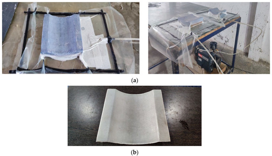
Figure 4.
(a) Fabrication process of curved glass/epoxy laminate using vacuum bagging method. (b) Fabricated 112ROC laminate.
In this study, laminate homogenization was achieved using the vacuum bagging method, which is a common technique for manufacturing composite laminates. In this method, six layers of GFRP fabric and resin are stacked together, and the laminate is subjected to a vacuum environment during curing. This process ensures uniform resin distribution and fiber alignment across the layers, leading to a more consistent and homogeneous composite structure. Following this procedure, the specimens are maintained at a room temperature of 30 °C for 24 h to facilitate curing. After the laminate becomes cured, a visual inspection was conducted to check for any obvious defects, such as voids, cracks, or inconsistencies in the laminates. No significant defects were observed in any of the samples, and all were deemed suitable for testing. The vacuum bagging method produces stronger, lighter, and higher-quality composite parts with precise fiber-to-resin ratios compared to hand layup techniques. In this fabrication process, both flat and curved composite panels were prepared, employing a layup configuration of [0°/90°]3, which yields a final thickness of 1.2 ± 0.25 mm. Ultimately, the production included eight flat laminate specimens and sixteen curved laminate specimens, corresponding to two distinct ROC configurations. To determine the fiber-to-matrix ratio, a burnout test was conducted following the American Society for Testing and Materials (ASTM) D3171 standard, revealing a ratio of 56%. The test involves heating the GFRP laminate sample to ~800 °C to burn off the matrix material. The difference in weight before and after heating indicates the fiber content. This ratio is crucial for evaluating the laminate’s mechanical properties, including strength, stiffness, and impact resistance, all of which are key factors in optimizing the performance of GFRP composites.
2.2. Material Tests
In order to determine the mechanical properties of the prepared GFRP specimens, tensile, compression, shear, and short-beam shear tests were performed following the ASTM D3039, ASTM D3410, ASTM D4255, and ASTM D2344 standards, respectively. The tensile test involved pulling rectangular specimens measuring 250 × 25 mm2 until failure to evaluate tensile strength and modulus. The tensile test specimen dimensions and their results were compiled in Table 1. For the compression test, a specimen of size 140 × 25 mm2 was subjected to compression between platens to determine compressive strength and modulus. In the shear test, a lateral force was applied to rectangular specimens of 250 × 25 mm2 to assess the in-plane shear strength and modulus. The short-beam shear test utilized rectangular specimens measuring 20 × 5 mm2 to evaluate interlaminar shear strength (ILSS), with the specimen undergoing a three-point bending load that induced shear failure between the laminate layers. These tests yield essential information regarding the material’s response to tensile, compressive, shear, and bending forces. The stress–strain curve from the tensile test extracted through experiment and numerical analysis are compared in Figure 5. Each testing procedure involved five specimens to accurately assess the tensile, compression, shear, and ILSS characteristics. The material properties of the glass/epoxy panels obtained from the material test are given in Table 2.

Table 1.
Tensile test data of GFRP specimen.
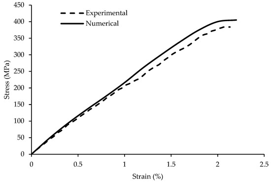
Figure 5.
Stress–strain curve of glass/epoxy [0/90] laminate—experimental vs. numerical.
Table 2.
Properties of glass/epoxy laminate.
2.3. Impact Tests
The impact test was conducted using a high-velocity impact test setup, as shown in Figure 6. The setup includes an air compressor, storage cylinder, projectile gun, fixtures, and two ballistic chronographs. The compressor stores air, building pressure to launch projectiles at varying speeds (40 m/s to 116 m/s). The impact and residual velocities are measured using chronographs. A 15 mm diameter ballistic gun was used to project the impactors. To evaluate the error percentage related to the velocity of the projectile, several test firings were performed without target specimens. Velocity measurements were obtained using both front and rear chronographs, which indicated an average variation of 0.3 m/s in the projectile’s speed. To ensure the dependability of the impact test results, three identical panels were impacted at the same velocity. After achieving consistent results from these initial tests, the actual experimental procedures commenced.
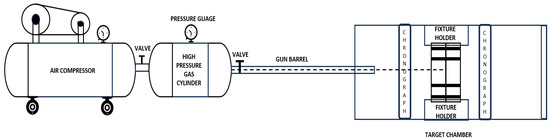
Figure 6.
Schematic representation of the impact test setup.
Three configurations of specimens such as flat, 203 mm ROC, and 112 mm ROC panels were considered for this impact study based on the height–length ratio of 9.33 and 18.66, respectively. The flat laminate specimen is 140 mm × 140 mm and the curved laminate is 210 mm × 210 mm (projected size). Here, the size of the curved laminate is considered more than the flat laminate for better placement and for holding it in the fixture. However, the area of exposure to the ballistic impact after the specimen becomes fixed in the fixture is 80 mm × 80 mm for all the configurations. Each fixture consists of two parts, a lower and an upper part, as shown in Figure 7. The specimen was kept between the lower and upper part, and it was joined using bolt connections. Spherical-shaped and 60 deg conical-shaped steel impactors were used to impact the specimens with a diameter of 12 mm and mass of 10 g, as shown in Figure 8. The choice of these projectiles is based on their ability to simulate real-world impact scenarios and represent the various shapes commonly encountered in practical applications. By using both types of projectiles under different panel curvatures, this study can provide a broader understanding of how different shapes affect the damage mechanisms and performance of GFRP laminates under varying impact conditions. The steel projectile was chosen for high-velocity impact analysis on GFRP due to its relevance in real-world applications, such as military and automotive testing, where steel projectiles are commonly used. Steel’s known mechanical properties, such as high hardness and density, provide a controlled and repeatable testing environment, ensuring the consistency and reliability of the results. This choice allows for meaningful comparisons with the existing literature and industry standards. Specimens are fixed in the impact machine using the respective fixtures (three separate fixtures for three specimen configurations). The energy absorption capability of the laminates can be measured with initial velocity (Vi) and residual velocity (Vr) using
where m is the mass of the projectile. Various velocity conditions were applied for the projectile to identify the ballistic limit of the specimen. In order to verify the accuracy of the residual velocity and damage pattern, the 203 mm ROC panel underwent testing at the same initial velocity three times. For each configuration of the specimen and each projectile, four specimens were tested. The velocities for each specimen configuration and each impactor configuration will be different.
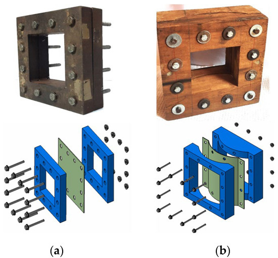
Figure 7.
(a) Flat plate fixture in steel. (b) Curved plate fixture in wood.
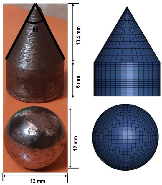
Figure 8.
Original and FE modeled projectiles.
3. Numerical Analysis
3.1. Finite Element Model
For each configuration of the specimen and each projectile, four specimens were tested. The velocities for each specimen configuration and each impactor configuration will be different. The results acquired from the experimental high-velocity impact tests, focusing on energy absorption behavior and the modes of laminate damage, were confirmed using a finite element (FE) study. Numerical simulations were performed using the FE software LS DYNA Version R14. To simulate the GFRP laminate subjected to high-velocity impacts, each ply of the laminate needs to be modeled as a separate layer to visualize the failure modes in detail, including the inter-laminar delamination and growth of the crack at projectile hitting region. The laminates and projectiles were modeled in the preprocessing tool LS-Prepost. The FE models of projectile and target panels are shown in Figure 8 and Figure 9. The quality of meshing is a critical factor that determines both the accuracy of the results and the computational time required for the analysis in numerical studies. A mesh convergence analysis was conducted using the flat plate impacted with a spherical projectile with a velocity of 72 m/s, varying the mesh length from 0.25 mm to 2 mm, in order to determine the optimal element size that aligns with the experimental results while also improving computational efficiency. It was found, as shown in Figure 10, that the four noded quad elements with 0.5 mm mesh lengths gave an accurate analysis. The number of elements and nodes of the FE model used in this study are given in Table 3. The specimen was drawn in the x–z plane so that the direction of the projectile would be along the y-axis. The conical and spherical projectiles were represented as rigid bodies utilizing 3D solid elements provided by the LS-DYNA Algorithm. As per the figures, the area exposed to the projectile impact was only 80 mm × 80 mm. So, the FE models were built only for the area exposed to the projectile to save on computational solving time.
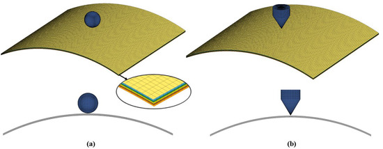
Figure 9.
Iso and side view of 112 mm ROC FE models (a) with spherical projectile and (b) conical projectile.
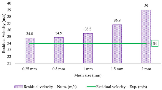
Figure 10.
Mesh convergence of the flat laminate subjected to 72 m/s velocity with a spherical projectile.
Table 3.
Element and node counts of the FE model.
3.2. Material Model
In order to predict the impact behavior of composite materials, an appropriate material model can be selected from the LS-DYNA material library, namely MAT_ENHANCED_COMPOSITE_DAMAGE (*Mat_054). This model, validated for shell elements only, is founded on the Chang—Chang failure criteria [30]. This MAT_054 material model is well-suited for modeling glass/epoxy laminates because it accurately captures the complex failure mechanisms, including matrix cracking, fiber failure, and delamination. It allows for progressive damage evolution, simulating the degradation of material properties under stress or impact. This model’s ability to separately account for fiber and matrix failure, along with delamination, makes it ideal for predicting the behavior and damage progression in laminated composites. Users are allowed to define custom orthotropic characteristics by selecting a relevant local material axis and determining the necessary constitutive constants. The constitutive equations are employed to derive the strains (εi, i = 11, 22 and 12) based on the corresponding stresses (σi, i = 11, 22, and 12) within the context of plane stress [8]. The following formulation represents the equations that exhibit variation throughout the thickness of the shell:
The four primary elastic constants that remain undamaged are designated as E1 and E2, representing the Young’s moduli in the principal orthotropic directions, G12, which is the in-plane shear modulus, and ν12, the Poisson’s ratio. In the context of plane stress conditions, the relationship between shear stress and strain is characterized by the parameter α. The criteria for failure are established on the basis of both tensile and compressive failure modes of the fiber and matrix [31].
The material model is defined by a linear elastic behavior in tension, compression, and shear until the stresses of the elements reach their yield strengths. The projectile was modeled using rigid material model (*MAT_RIGID), as the projectile is stiffer than the target specimens. The material properties of steel, as presented in Table 4, are assigned to the projectiles, given that these properties can significantly affect the contact modeling.
Table 4.
Properties of steel impactor.
For the tensile fiber mode,
For the compressive fiber mode,
For the tensile matrix mode,
For the compressive matrix mode,
3.3. Influence of Strain Rate
GFRP composites are strain rate sensitive and hence the strain rate effects are considered using Cowper–Symonds equations [32]. The strain rate parameters for strength (A, mσ) and modulus (B, mE) of composites are given by
Experimental values for strength and modulus were analyzed in a spreadsheet using the above equations to forecast the impact of the strain rate on the tensile strength of the composites. Figure 11 illustrates the relationship between strain rate and dynamic tensile strength, revealing that tensile strength rises as strain rate increases. Notably, tensile strength nearly doubles at a strain rate of approximately 1000. Hence, all further analyses will incorporate the effects of strain rate.
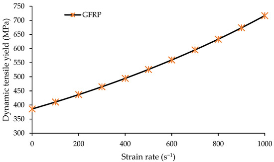
Figure 11.
Strain rate versus dynamic tensile strength.
3.4. Contact Modeling
To have the proper failure of plies similar to the experimental results, it is important to assign the proper contact properties. In this study, there are two contact algorithms were used to achieve the accurate results. For the contact between the laminates and rigid projectile, *CONTACT_ ERODING_ SURFACE_ TO_ SURFACE was used. This enables the contact to function properly as the layers of the components wear away during penetration. Also, this model accurately simulates the interaction between the laminate and projectile by allowing for material erosion upon contact. It captures realistic damage mechanisms, such as material loss and friction, and prevents unrealistic sticking or penetration, providing a more accurate representation of high-energy impacts. In order to facilitate the appropriate interaction and bonding between two adjacent plies, specifically addressing the inter-laminar delamination feature, the *CONTACT_ AUTOMATIC_ SURFACE_TO_ SURFACE_ TIEBREAK option was employed [33]. It accurately captures the initiation and progression of interlaminar damage, ensuring realistic simulation of failure mechanisms like ply separation. This model also prevents unrealistic bonding between layers, providing more accurate predictions of laminate behavior under loading conditions. The separation of nodes that were initially connected takes place when the below specified failure criterion is met.
where SFLS and NFLS denote the shear failure and interfacial normal strengths, respectively, while σs and σn refer to the shear and normal stresses exerted on the contact areas throughout the impact process. Meeting the conditions mentioned in Equation (13) results in the elimination of interfacial stress, thereby allowing for the two connected nodes to separate [34,35].
3.5. Boundary Conditions
The boundary conditions employed in this numerical model correspond precisely to the conditions applied in the experimental setup. All four side edges of the specimen were fixed for all three specimen configurations. For the curved specimen configurations, the fixture was arranged in such a manner that its convex side was oriented towards the face of impact, leading to the impactor striking the central point of the panel. The movement of the impactor was limited to the Y axis, with the X and Z axes were constrained. For the sake of simplicity, it was assumed that the mass is concentrated on the impactor, which possesses a total mass of 10 g. Initial velocity conditions were assigned to the projectile.
4. Results and Discussion
4.1. Residual Velocity Analysis
Assessing the residual velocity of a projectile as it breaches a barrier is essential for both civilian safety and military applications. The residual velocities were measured from the experiment using the velocity chronograph, which was placed after the fixture. This chronograph measures the velocity of the impactor after it passes through the specimen. The residual velocities measured from the experimental and numerical analysis are compared in Table 5 for spherical and conical impactors. The analysis reveals a commendable level of consistency between the numerically estimated values and the results derived from the experiments. Figure 12 shows the residual velocities for the respective impact velocities with spherical and conical projectiles. From Figure 12 in general, an increase in panel curvature increases the perforation strength. Comparing the projectile behaviors over the different plate configurations, the conical impactor easily penetrates the panel in the order of the panel curvature.
Table 5.
Experimental and numerical comparisons of residual velocities under spherical- and conical-shaped projectiles.
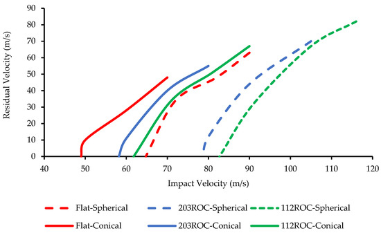
Figure 12.
Experimental results of impact test—residual velocities vs. impact velocity.
4.2. Ballistic Limit Analysis
An essential metric for assessing the impact performance of a target plate is ballistic limit velocity (VBL). This parameter is defined as the lowest velocity at which a projectile can fully penetrate the target plate. The vector directions of the initial velocity and the residual velocity are approximately aligned. Based on the principle of conservation of energy, Arivoli [36] made predictions regarding the ballistic limit of plain-woven E-glass/epoxy laminates using the following basic relationship:
where mp represents the mass of the projectile, VBL is the ballistic limit velocity, Vi is the impact velocity, and Vr is the residual velocity of the projectile after completely perforating the target. It is assumed that the projectile maintains its rigidity and that the mass of the fragment representing the projectile remains unchanged. Equation (14) can be reduced further to
To find this ballistic limit velocity of flat and curved specimens, a comprehensive range of impact velocities for the projectile were chosen for the experiment, ranging from 50 to 116 m/s for the spherical projectile and from 40 to 90 m/s for the conical projectile. The reaction of the specimens is analyzed in terms of both the rebound and penetration of the projectile. Also, the ballistic limit velocity will vary for different panel configurations and different impactor shapes. The experimental and numerical results of the ballistic limit velocity for three configurations of flat and curved specimens and for two configurations of projectiles are in Table 6, and the results are well correlated. Numerical results deviations up to 10% in structural engineering are generally acceptable due to material variability, experimental uncertainties, and numerical approximations. Industry standards and previous studies support this tolerance, as real-world conditions introduce inherent uncertainties. The results from this study remain within a reasonable and practical accuracy range. The influence of the panel configuration on the ballistic limit is shown in Figure 13 using different projectiles with similar mass (10 g).
Table 6.
Experimental and numerical comparisons of ballistic limit velocities.
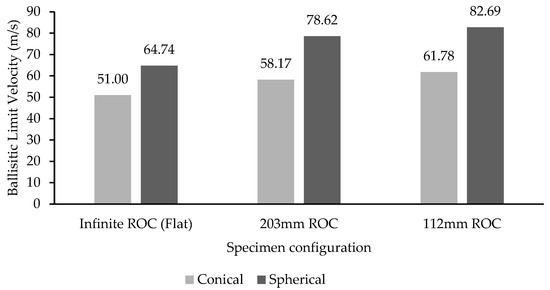
Figure 13.
Ballistic limit velocity comparison for three panel configurations under conical and spherical impactors.
From the results, it was observed that the 112 mm ROC panel has the highest ballistic limit against a spherical projectile. The lowest ballistic limit is achieved with a conical projectile impacting a flat plate. The ballistic limit is increasing gradually with panel curvature for both projectiles. Comparing both projectile performances, the spherical projectile has more ballistic limits in all of the panel configurations. This is due to the geometrical property of the 60-degree conical projectile. It has a sharp leading edge to tear the panels, and increasing the diameter of conical shape from the leading edge helps to penetrate easily into the specimens. The time taken to the projectile to penetrate the different configurations of panels is shown in Figure 14. In Figure 15, a comparison is made between the different panel configurations with the spherical and conical projectile’s time to hit the panels with ~70 m/s velocity. Curved panels impacted with a spherical projectile did not have penetrated (rebounded) panels at 70 m/s. So, it was not considered for the above comparison. Among the remaining configurations, the time taken by the conical projectile to penetrate all of the panels is almost the same. The time curve was linear on the conical projectile and exponential on the spherical projectile. There is a sudden drop in velocity within 0.05 ms when the flat plate impacted with spherical projectile, whereas, in the conical projectile, velocity drop happened gradually until 0.2 ms.
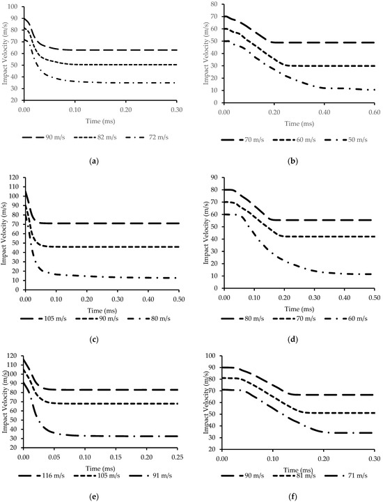
Figure 14.
Time taken to penetrate the specimen under different velocities: (a) flat plate with spherical projectile, (b) flat plate with conical projectile, (c) 203ROC plate with spherical projectile, (d) 203ROC plate with conical projectile, (e) 112ROC plate with spherical projectile, and (f) 112ROC plate with conical projectile.
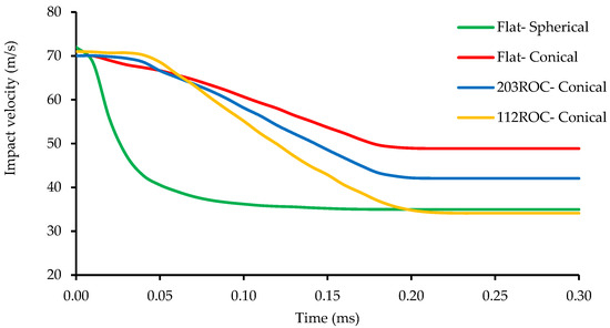
Figure 15.
Time taken to penetrate the panels on 70 m/s with the spherical and conical projectiles.
4.3. Energy Absorption Capability
A critical characteristic of GFRP composites utilized in protective applications is their ability to absorb energy, particularly when subjected to high-velocity impacts. Upon impact with the laminated plate, the projectile may either penetrate the surface or bounce back, depending upon its velocity. When its velocity is significantly reduced, it will eventually come to a complete stop before reversing direction. However, at elevated velocities, the projectile will penetrate the specimen, and its speed will not diminish to zero. The energy that the plate absorbs from the projectile is known as the perforation energy (Eab) and can be estimated from the following equation:
where mp is the mass of the projectile, Vi is the impact velocity and Vr is the residual velocity of the projectile [9].
The impactor will stop when the plate absorbs all the kinetic energy of the projectile. The energy absorption capability of all three specimen configurations under spherical and conical projectiles measured in the experiments are presented in Table 7. According to Figure 16, the panel with a radius of curvature (ROC) of 112 mm exhibits the highest energy absorption capacity when compared to other panel configurations for both spherical and conical projectiles. In contrast, the flat panel demonstrates the lowest energy absorption capacity. This indicates that an increase in curvature of the panels correlates with an enhancement in energy absorption capacity. From the perspective of the projectile, the panels absorbed the least energy when impacted by a conical projectile.
Table 7.
Experimental results of energy absorption under spherical- and conical-shaped projectiles.
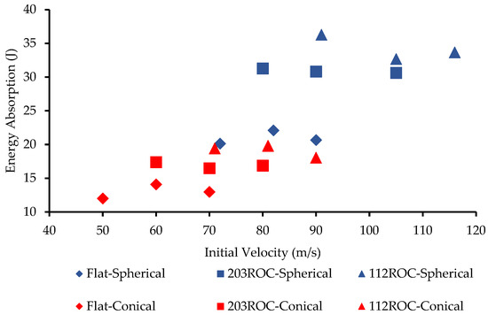
Figure 16.
Energy absorbed by the panels under the conical and spherical impactors.
4.4. Damage Analysis
GFRP materials respond differently to high-velocity impacts compared to metals or traditional materials. Understanding the dynamics of the impact is crucial. Factors such as the mass of the projectile, impact velocity, and impact angle all influence the extent and nature of the damage [37,38]. GFRP materials have a limited ability to absorb energy compared to metals. The design and composition of GFRP structures need to consider energy absorption requirements to prevent catastrophic failure. Generally, the kinetic energy of the projectile is dispersed through fiber extending, fiber breakage, matrix breaking, laminate deflection, delamination, and debonding [19]. The primary mechanisms for energy absorption in composites during the perforation process are attributed to the delamination of both the fiber and the matrix [39]. Damage patterns on the front and rear faces of the flat, 203 ROC, and 112 ROC panels after the velocity impacts are shown in Figure 17, Figure 18, and Figure 19, respectively. Here, the damage patterns of low-velocity and high-velocity conditions tested for each panel configuration with spherical and conical impactors are presented. The flat plate at 60 m/s, 203 ROC plate at 70 m/s, and 112 ROC plate at 80 m/s with spherical impactor and flat plate at 40 m/s, 203 ROC plate at 50 m/s, and 112 ROC plate at 60 m/s with conical impactor were not perforated, but bounced back after impact, as shown in Figure 17b,d, Figure 18b,d, and Figure 19b,d. For the remaining velocities tested, all of the panels were penetrated and perforated, as shown in Table 7.
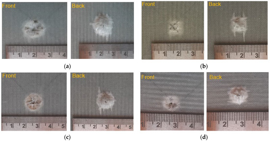
Figure 17.
Damage patterns on the front and back faces of the flat plate under (a) the spherical impactor with 90 m/s, (b) the spherical impactor with 60 m/s (rebounded), (c) the conical impactor with 70 m/s, and (d) the conical impactor with 40 m/s (rebounded).
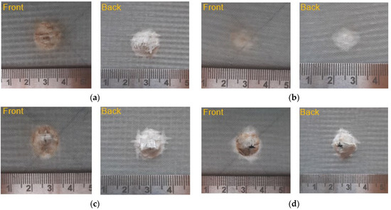
Figure 18.
Damage patterns on the front and back faces of the 203ROC plate under (a) the spherical impactor with 105 m/s, (b) the spherical impactor with 70 m/s (rebounded), (c) the conical impactor with 80 m/s, and (d) the conical impactor with 50 m/s (rebounded).
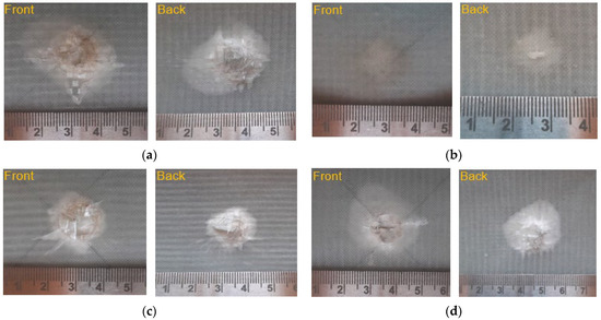
Figure 19.
Damage patterns on the front and back faces of the 112ROC plate under (a) the spherical impactor with 116 m/s, (b) the spherical impactor with 80 m/s (rebounded), (c) the conical impactor with 90 m/s, and (d) the conical impactor with 60 m/s (rebounded).
Once the projectile hits the laminates, distinct damage characteristics appear on the front (impact) face and back face due to the rapid energy transfer and unique stress distribution across the thickness of laminate. In flat laminates, the failures shown in Figure 17 occur due to high tensile and shear stresses, often leading to delamination [7]. Fiber breakage happens due to the tensile loads exceed the fiber strength, while matrix debonding is caused by interfacial shear stresses induced between the fibers and the matrix. In curved laminates, from Figure 18 and Figure 19, due to the non-uniform stress distribution—where the outer layers are in tension and the inner layers are in compression—leads to an increased likelihood of fiber breakage on the outer surface and matrix debonding due to differential strain. Both failure modes are interconnected, as matrix debonding weakens the fiber–matrix bond, promoting further fiber breakage and potential delamination, especially in regions with high bending stresses or sharp curvatures. As the curvature of laminates increase, their ballistic resistance improves. The increased curvature enhances the laminate’s ability to distribute and dissipate impact energy, raising the ballistic limit. Unlike flat laminates, where impact energy is concentrated at the point of contact, curved laminates spread this energy more efficiently, reducing localized damage such as fiber rupture and delamination. This increased stiffness and better energy distribution provide higher penetration resistance, making curved panels more effective at resisting penetration and crater formation, particularly under conical impacts. However, curved panels experienced the fiber rupture in the outer layers and delamination due to differential strain, but generally perform better than flat panels due to their enhanced ability to resist impact and distribute energy more effectively.
The lower ballistic limit of the conical projectile, despite its sharp leading edge, is due to the premature initiation of failure mechanisms in the GFRP. While the conical shape aids initial penetration by concentrating impact force, it leads to localized damage like delamination and matrix cracking that reduces the material’s ability to absorb energy at later stages. In contrast, the spherical projectile distributes the impact force more evenly, allowing for a more gradual engagement of failure mechanisms, which results in better energy absorption and a higher resistance to penetration. Thus, the conical projectile’s sharp geometry causes rapid damage onset, limiting its overall performance compared to the spherical projectile. Impact due to the conical projectile causes a crater on the impact face, with material often being expelled from the impact site [27]. High energy often pulverizes the fibers at the point of impact, leading to immediate fiber breakage. The spherical projectile made an indentation at low velocities and matrix cracking at high velocities in both flat and curved panels. At high velocity, the front face showed shattered fibers and fragments, as the brittle fibers cannot absorb the energy without fracturing. Delamination is triggered instantly on the impact face and radiates outward as the energy disperses. As the energy propagates through the panel, severe delamination occurs on the back face on curved panel, resulting in a larger delaminated area than on the front. This also caused matrix cracking, which is often more pronounced on the back face, as it is the last layer to absorb the transferred energy.
In scenarios involving rebounding or non-perforation, the damage area is comparatively smaller for flat plates; however, fiber pull-out is observed for both spherical and conical impactors, as illustrated in Figure 17b,d. For the curved panel configurations, when impacted by a spherical object, the rebounding scenario does not result in significant damage, as depicted in Figure 18b and Figure 19b. Internally, these panels experience matrix debonding and delamination. Conversely, when subjected to a conical impactor, the sharp leading edge leads to fiber breakage and fiber pull-out, as demonstrated in Figure 18d and Figure 19d.
In the course of the perforation process, it was observed that, among all of the panel configurations, the 112 ROC panel exhibited a higher quantity of fiber and matrix area that was collapsed by the impactor, as illustrated in Figure 19a. The inspection of the rear side of the plates (Figure 20) clearly indicates that the mechanisms of failure involve both fiber failure and delamination. Although visual inspection cannot reveal matrix cracking, it is among the earliest damage mechanisms observed in composite laminates. Its occurrence is critical, as it triggers additional failure modes, such as delamination [31].
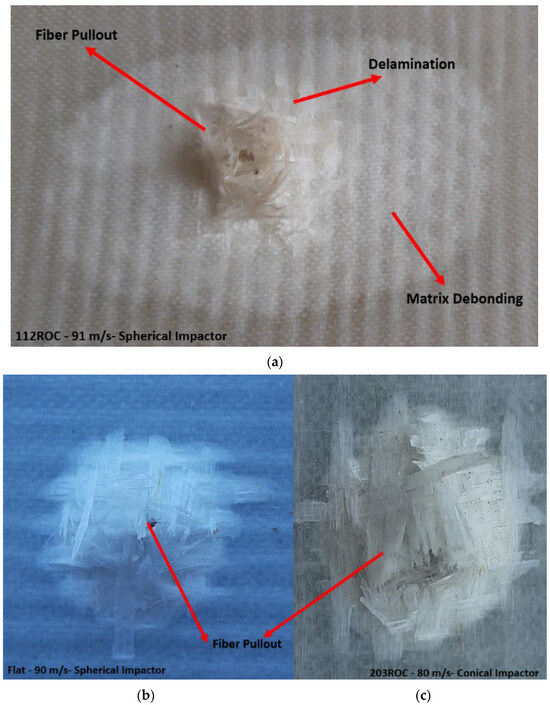
Figure 20.
Failure modes of GFRP laminates: (a) 112ROC panel on 91 m/s, (b) flat panel on 90 m/s, and (c) 203ROC panel on 80 m/s.
As the panel curvature increases, the damage patterns on the front and back faces are diversified. In flat laminates, damage on the front face is concentrated at the impact point, causing fiber rupture, matrix debonding, and cratering, while the back face shows less severe delamination and matrix cracking. In curved laminates, front face damage is more spread out, with fiber rupture in outer layers due to tension and matrix debonding from differential strain. The back face experiences more extensive delamination and matrix cracking due to better energy absorption and bending stresses, making damage more severe than in flat laminates. Figure 21 and Figure 22 represent the damaged area of the front and rear faces of three panel configurations concerning impact velocity with spherical and conical impactors, respectively. The extent of the damage is approximated as a circular area, characterized by a specified diameter. As illustrated in Figure 21 and Figure 22, it is evident that the damaged area expands in correlation with the increasing curvature of the panel.
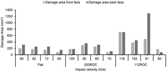
Figure 21.
Damage area of three panel configurations caused by the spherical impactor under different velocity conditions.
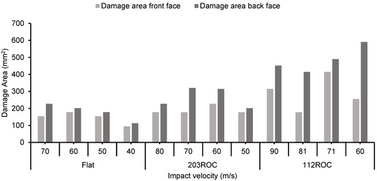
Figure 22.
Damage area of three panel configurations caused by the conical impactor under different velocity conditions.
The damage area measured on the flat plate had the minimal and maximum on the 112ROC panel. In comparison, concerning projectile shape, the conical impactor had the smallest damage area when compared to the spherical-shaped projectile. The data presented in Figure 21 and Figure 22 indicate that the damage area on the front face attained a peak value of approximately 707 mm2 at a velocity of 116 m/s, while the rear face exhibited a maximum damage area of 1296 mm2 at a velocity of 91 m/s, resulting from the impact of a spherical projectile on the 112 ROC panel. In Figure 23, the stepwise deformation pattern of the GFRP panels is presented. From Figure 20, Figure 21 and Figure 23, it is evident that the damage due to the spherical impactor is more than the damage caused by the conical impactor.
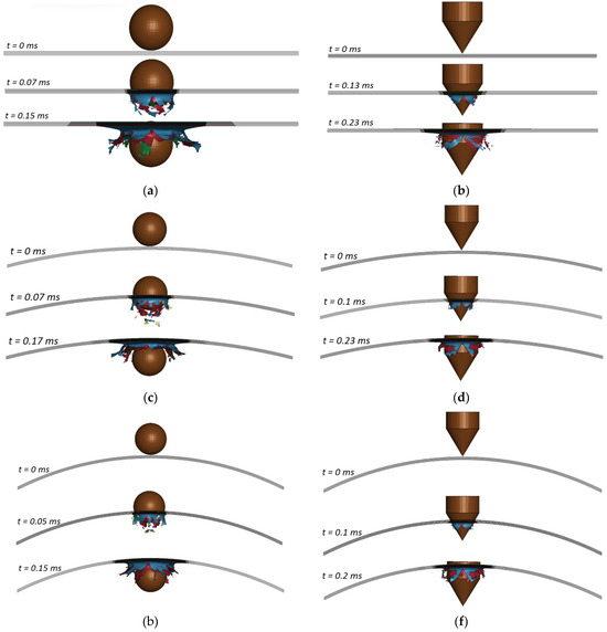
Figure 23.
Stepwise deformation of the panels with spherical and conical impactors under different velocities: (a) 90 m/s, (b) 70 m/s, (c) 105 m/s, (d) 80 m/s, (e) 116 m/s, and (f) 90 m/s.
5. Conclusions
This study analyzes the impact behavior of GFRP flat plates and curved composite plates impacted by spherical and conical projectiles. Using the experimental test conditions and material properties, a numerical simulation was carried out using the explicit FE tool LS-DYNA. The experimental and numerical findings were evaluated based on residual velocity and energy absorption capacity, demonstrating a strong correlation with a maximum deviation of 6%. The main conclusions made from this study are listed below:
- (1)
- The findings from the material tests reveal that the mechanical properties of GFRP laminates are quantified as follows: a tensile modulus of 20 GPa, a tensile strength of 386 MPa, a compressive strength of 72.6 MPa, a shear strength of 105 MPa, and an interlaminar shear stress of 10.3 MPa.
- (2)
- This research indicates that the panel with a 112 mm radius of curvature (ROC) exhibited superior ballistic limit velocity and energy absorption capabilities when compared to both the 203 mm ROC and flat panels. A decrease in the panel’s radius of curvature correlates with an increase in its energy absorption. Specifically, the ballistic limit velocity of the 112 mm ROC panel surpassed that of the flat panels by 22% for spherical impactors and by 17% for conical projectiles. The recorded ballistic limit velocities for the flat, 203 mm ROC, and 112 mm ROC panels were 64.74 m/s, 78.62 m/s, and 82.69 m/s for spherical impactors, and 51 m/s, 58 m/s, and 61.78 m/s for conical impactors, respectively.
- (3)
- The maximum energy absorption of the 112ROC panel is 36.3 J when subjected to a 91 m/s spherical impact, resulting in the largest damage area of 1296 mm2 on its backside. The spherical projectile causes more damage to the panel than the conical projectile due to its larger contact area with the panel.
- (4)
- The primary failure mechanisms identified in the 112ROC panel subjected to a spherical impact at 91 m/s include delamination, fiber pullout, and matrix debonding. Additionally, the 112ROC panel demonstrated a greater extent of fiber and matrix area that was compromised by the impactor.
The findings on the ballistic limit and energy absorption of curved panels have practical applications across several industries. In the aerospace and automotive sectors, they can enhance impact resistance in components like aircraft fuselages and vehicle body panels. In defense, they contribute to better protective gear and vehicle armor. Additionally, these findings can improve the durability of marine structures, wind turbine blades, and critical infrastructure by optimizing energy absorption and prolonging product lifecycles. Understanding how curvature affects these properties helps design safer, more efficient materials for various applications.
This study has some limitations, including that the range of impact velocities tested (40–116 m/s) is constrained by the capacity of the compressor and air storage cylinder used to generate high-velocity impacts, which may limit the broader applicability of the results. Additionally, assumptions made in the numerical model, along with experimental uncertainties, could affect the accuracy of the simulations. Future research could address these limitations by expanding the velocity range to investigate damage behavior at both very high and low velocities, increasing the number of samples tested, and refining the numerical model to include factors such as temperature effects. These improvements would provide a deeper understanding of GFRP composite behavior under a wider range of real-world conditions.
Author Contributions
Conceptualization, C.A.; methodology, C.A.; software, C.A.; validation, C.A. and K.R.; formal analysis, C.A.; investigation, C.A.; data curation, C.A.; writing—original draft preparation, C.A.; writing—review and editing, K.R.; visualization, C.A.; supervision, K.R. All authors have read and agreed to the published version of the manuscript.
Funding
This research received no external funding.
Data Availability Statement
Data available within the article itself.
Conflicts of Interest
The authors declare no conflicts of interest.
References
- Petron. Glass Fiber Reinforced Polymer (GFRP). Available online: https://petronthermoplast.com/glass-fiber-reinforced-polymer/ (accessed on 5 August 2024).
- Morampudi, P.; Namala, K.K.; Gajjela, Y.K.; Barath, M.; Prudhvi, G. Review on glass fiber reinforced polymer composites. Mater. Today Proc. 2020, 43, 314–319. [Google Scholar] [CrossRef]
- Sawada, T.; Kusaka, T. Strength predictions by applied effective volume theory in short-glass-fiber-reinforced plastics. Polym. Test 2017, 62, 143–153. [Google Scholar] [CrossRef]
- Carvalho, D.; Ferreira, N.; França, B.; Marques, R.; Silva, M.; Silva, S.; Silva, E.; Macário, D.; Barroso, L.; Silva, C.J.; et al. Advancing sustainability in the automotive industry: Bioprepregs and fully bio-based composites. Compos. Part C Open Access 2024, 14, 100459. [Google Scholar] [CrossRef]
- Feito, N.; Loya, J.A.; Muñoz-Sánchez, A.; Das, R. Numerical modelling of ballistic impact response at low velocity in aramid fabrics. Materials 2019, 12, 2087. [Google Scholar] [CrossRef]
- Alam, S.; Aboagye, P. Numerical Modeling on Ballistic Impact Analysis of the Segmented Sandwich Composite Armor System. Appl. Mech. 2024, 5, 340–361. [Google Scholar] [CrossRef]
- Chen, F.; Peng, Y.; Chen, X.; Wang, K.; Liu, Z.; Chen, C. Investigation of the Ballistic Performance of GFRP Laminate under 150 m/s High-Velocity Impact: Simulation and Experiment. Polymers 2021, 13, 604. [Google Scholar] [CrossRef]
- Shyamsunder, L.; Maurya, A.; Rajan, S.D.; Cordasco, D.; Revilock, D.; Blankenhorn, G. Impact simulation of composite panels for aerospace applications. Compos. B Eng. 2022, 247, 110320. [Google Scholar] [CrossRef]
- Yang, C.; Gao, Y.; Guo, W.; Yang, Y.; Xu, P.; Alqahtani, M.S. High-velocity impact behavior of curved GFRP composites for rail vehicles: Experimental and numerical study. Polym. Test 2022, 116, 107774. [Google Scholar] [CrossRef]
- Coelho, C.A.C.P.; Navalho, F.V.P.; Reis, P.N.B. Impact response of laminate cylindrical shells. Frat. Integrita Strutt. 2019, 13, 411–418. [Google Scholar] [CrossRef]
- Menna, C.; Asprone, D.; Caprino, G.; Lopresto, V.; Prota, A. Numerical simulation of impact tests on GFRP composite laminates. Int. J. Impact Eng. 2011, 38, 677–685. [Google Scholar] [CrossRef]
- Donadon, M.V.; Iannucci, L.; Falzon, B.G.; Hodgkinson, J.M.; de Almeida, S.F.M. A progressive failure model for composite laminates subjected to low velocity impact damage. Comput. Struct. 2008, 86, 1232–1252. [Google Scholar] [CrossRef]
- Yang, C.; Chen, Z.; Yao, S.; Xu, P.; Li, S.; Alqahtani, M.S. Parametric study on the crushing performance of a polyurethane foam-filled CFRP/Al composite sandwich structure. Polym. Test 2022, 108, 107515. [Google Scholar] [CrossRef]
- Castellano, A.; Fraddosio, A.; Piccioni, M.D. Quantitative analysis of QSI and LVI damage in GFRP unidirectional composite laminates by a new ultrasonic approach. Compos. B Eng. 2018, 151, 106–117. [Google Scholar] [CrossRef]
- Muhi, R.J.; Najim, F.; de Moura, M.F.S.F. The effect of hybridization on the GFRP behavior under high velocity impact. Compos. B Eng. 2009, 40, 798–803. [Google Scholar] [CrossRef]
- Seifoori, S.; Izadi, R.; Yazdinezhad, A.R. Impact damage detection for small- and large-mass impact on CFRP and GFRP composite laminate with different striker geometry using experimental, analytical and FE methods. Acta Mech. 2019, 230, 4417–4433. [Google Scholar] [CrossRef]
- Mishra, Y.; Kumar, N.H.; Priya, I.I.M. Simulation of high velocity impact test on GFRP. IOP Conf. Ser. Mater. Sci. Eng. 2020, 912, 052004. [Google Scholar] [CrossRef]
- Seifoori, S.; Parrany, A.M.; Mirzarahmani, S. Impact damage detection in CFRP and GFRP curved composite laminates subjected to low-velocity impacts. Compos. Struct. 2021, 261, 113278. [Google Scholar] [CrossRef]
- Zhao, D.; Liu, T.; Lu, X.; Meng, X. Experimental and numerical analysis of a novel curved sandwich panel with pultruded GFRP strip core. Compos. Struct. 2022, 288, 115404. [Google Scholar] [CrossRef]
- Saghafi, H.; Minak, G.; Zucchelli, A. Effect of preload on the impact response of curved composite panels. Compos. B Eng. 2014, 60, 74–81. [Google Scholar] [CrossRef]
- Song, Z.; Le, J.; Whisler, D.; Kim, H. Skin-stringer interface failure investigation of stringer-stiffened curved composite panels under hail ice impact. Int. J. Impact Eng. 2018, 122, 439–450. [Google Scholar] [CrossRef]
- Serhat, G.; Basdogan, I. Design of curved composite panels for optimal dynamic response using lamination parameters. Compos. B Eng. 2018, 147, 135–146. [Google Scholar] [CrossRef]
- Haque, B.Z.; Gillespie, J.W. A new penetration equation for ballistic limit analysis. J. Thermoplast. Compos. Mater. 2015, 28, 950–972. [Google Scholar] [CrossRef]
- Bidi, A.; Liaghat, G.; Rahimi, G.; Hadavinia, H. Experimental and numerical analysis of impact on curved nanocomposite panels. Mech. Adv. Mater. Struct. 2019, 26, 1365–1375. [Google Scholar] [CrossRef]
- Chinnarasu, A.; Ramajeyathilagam, K. Low velocity impact behavior of curved nano composite Panel- A Numerical study. Mater. Today Proc. 2023. [Google Scholar] [CrossRef]
- Razali, N.; Sultan, M.T.H.; Safri, S.N.A.; Basri, S.; Yidris, N.; Mustapha, F. High Velocity Impact Test on Glass Fiber Reinforced Polymer (GFRP) Using a Single Stage Gas Gun (SSGG)-An Experimental Based Approach. Appl. Mech. Mater. 2014, 564, 376–381. [Google Scholar] [CrossRef]
- Jordan, J.B.; Naito, C.J. An experimental investigation of the effect of nose shape on fragments penetrating GFRP. Int. J. Impact Eng. 2014, 63, 63–71. [Google Scholar] [CrossRef]
- Dey, S.; Børvik, T.; Hopperstad, O.S.; Leinum, J.R.; Langseth, M. The effect of target strength on the perforation of steel plates using three different projectile nose shapes. Int. J. Impact Eng. 2004, 30, 1005–1038. [Google Scholar] [CrossRef]
- Bendarma, A.; Jankowiak, T.; Rusinetk, A.; Lodygowski, T.; Czarnota, C.; Bernier, R.; Khalfaoui, M. Experimental and Numerical Analysis of Aluminum-Polyethylene Composite Structure Subjected to Tension and Perforation Under Dynamic Loading for a Wide Range of Temperatures. J. Dyn. Behav. Mater. 2024, 10, 51–74. [Google Scholar] [CrossRef]
- Gladman, B. Ls-Dyna® Keyword User’s Manual. Available online: https://www.dynasupport.com/manuals/ls-dyna-manuals/ls-dyna_manual_volume_ii_r11.pdf. (accessed on 13 September 2024.).
- Ghasemnejad, H.; Furquan, A.S.M.; Mason, P.J. Charpy impact damage behavior of single and multi-delaminated hybrid composite beam structures. Mater. Des. 2010, 31, 3653–3660. [Google Scholar] [CrossRef]
- Naresh, K.; Shankar, K.; Velmurugan, R.; Gupta, N.K. High strain rate studies for different laminate configurations of bi-directional glass/epoxy and carbon/epoxy composites using DIC. Structures 2020, 27, 2451–2465. [Google Scholar] [CrossRef]
- Karthick, P.; Ramajeyathilagam, K. Numerical study of influence of target thickness and projectile incidence angle on ballistic resistance of the GFRP composites. Mater. Today Proc. 2021, 47, 992–999. [Google Scholar] [CrossRef]
- Dogan, F.; Hadavinia, H.; Donchev, T.; Bhonge, P.S. Delamination of impacted composite structures by cohesive zone interface elements and tiebreak contact. Cent. Eur. J. Eng. 2012, 2, 612–626. [Google Scholar] [CrossRef]
- Sy, B.L.; Fawaz, Z.; Bougherara, H. Numerical simulation correlating the low velocity impact behavior of flax/epoxy laminates. Compos. Part A Appl. Sci. Manuf. 2019, 126, 105582. [Google Scholar] [CrossRef]
- Chinnarasu, A.; Ramajeyathilagam, K. Numerical study on influence of target thickness on impact response of GFRP composites. Mater. Today Proc. 2023. [Google Scholar] [CrossRef]
- Memic, F.; Catovic, A. The influence of projectile impact velocity and target characteristics on the terminal ballistics parameters of small-caliber projectile. Def. Secur. Stud. 2024, 5, 46–64. [Google Scholar] [CrossRef]
- Ansari, M.M.; Chakrabarti, A. Ballistic Performance of Unidirectional Glass Fiber Laminated Composite Plate under Normal and Oblique Impact. Procedia. Eng. 2017, 173, 161–168. [Google Scholar] [CrossRef]
- Mohammadi, B.; Pourhosseinshahi, M.; Bakhtiari, M.Y. Simulation of energy dissipation mechanisms in evaluating the critical interlaminar strain energy release rate of cross-ply carbon/epoxy laminated composites. Theor. Appl. Fract. Mech. 2021, 114, 103003. [Google Scholar] [CrossRef]
Disclaimer/Publisher’s Note: The statements, opinions and data contained in all publications are solely those of the individual author(s) and contributor(s) and not of MDPI and/or the editor(s). MDPI and/or the editor(s) disclaim responsibility for any injury to people or property resulting from any ideas, methods, instructions or products referred to in the content. |
© 2025 by the authors. Licensee MDPI, Basel, Switzerland. This article is an open access article distributed under the terms and conditions of the Creative Commons Attribution (CC BY) license (https://creativecommons.org/licenses/by/4.0/).