Article

Effect of Yarn-Level Fibre Hybridisation on Thermomechanical Behaviour of 3D Woven Orthogonal Flax/E-Glass Composite Laminae

1
Department of Mechanical and Aerospace Engineering, University of Manchester, Manchester M13 9PL, UK
2
Northwest Composites Centre, University of Manchester, Manchester M13 9PL, UK
3
Department of Materials, University of Manchester, Manchester M13 9PL, UK
*
Author to whom correspondence should be addressed.
J. Compos. Sci. 2025, 9(3), 135; https://doi.org/10.3390/jcs9030135
Submission received: 14 February 2025 / Revised: 7 March 2025 / Accepted: 11 March 2025 / Published: 13 March 2025
(This article belongs to the Section Fiber Composites)

Abstract

:
This study investigates the novel role of yarn-level fibre hybridisation in tailoring thermomechanical properties and thermal residual stress (TRS) fields in the resin at both micro- and meso-scales of 3D orthogonal-woven flax/E-glass hybrid composites. Unlike previous studies, which primarily focus on macro-scale composite behaviour, this work integrates a two-scale homogenisation scheme. It combines microscale representative volume element (RVE) models and mesoscale repeating unit cell (RUC) models to capture the effects of hybridisation from the fibre to lamina scale. The analysis specifically examines the cooling phase from a curing temperature of 100 °C down to 20 °C, where TRS develops due to thermal expansion mismatches. Microstructures are generated employing a random sequential expansion algorithm for RVE models, while weave architecture is generated using the open-source software TexGen 3.13.1 for RUC models. Results demonstrate that yarn-level hybridisation provides a powerful strategy to balance mechanical performance, thermal stability, and residual stress control, revealing its potential for optimising composite design. Stress analysis indicates that under in-plane tensile loading, stress levels in matrix-rich regions remain below 1 MPa, while binder yarns exhibit significant stress concentration, reaching up to 8.71 MPa under shear loading. The study quantifies how varying fibre hybridisation ratios influence stiffness, thermal expansion, and stress concentrations—bridging the gap between microstructural design and macroscopic composite performance. These findings highlight the potential of yarn-level fibre hybridisation in tailoring thermomechanical properties of yarns and laminae. The study also demonstrates its effectiveness in reducing TRS in composite laminae post-manufacturing. Additionally, hybridisation allows for adjusting density requirements, making it suitable for applications where weight and thermal properties are critical.

1. Introduction

Natural fibre-reinforced polymer composites (NFRCs) are gaining popularity in automotive, civil, sports, and aerospace industries due to their availability, biodegradability, and processability [1,2]. However, NFRCs have limitations, including lower stiffness, strength, durability, and thermal performance [3]. To address these limitations, natural/synthetic fibre-based hybrid composites (NFHCs) have been developed [4,5,6]. By integrating natural and synthetic fibres, these NFHCs achieve a balance of mechanical properties and thermal stability. This makes them suitable for a variety of structural applications. Understanding the thermal behaviour of NFHCs is particularly important in temperature-sensitive environments where structures are exposed to variable temperature conditions.
During manufacturing and use, composites develop thermal residual stress (TRS) due to differences in thermomechanical properties between fibres and the matrix [7,8]. This stress arises primarily during the curing process, which includes isothermal curing and thermal cooling phases. During isothermal curing, the composites undergo polymerisation at elevated temperatures, usually between 100 °C and 250 °C for most traditional polymeric resins. This process leads to polymer contraction and increased stiffness, while the fibres remain unaffected. In the subsequent thermal cooling phase, the composites cool down to room temperature, leading to shrinkage and thermal cooling stresses [9]. Shrinkage stress occurs due to volume changes during polymerisation, as the polymer becomes rigid at its glass transition temperature. Thermal cooling stress, on the other hand, is caused by the different coefficients of thermal expansion (CTE) between the matrix ( 20 100 × 10 6 / K ) and fibres (e.g., carbon fibres with a CTE range of 1 × 10 6 / K to 0.5 × 10 6 / K ). During cooling, both the matrix and fibres contract. However, the matrix’s contraction is restricted by its bond with the fibres. In contrast, fibres not only contract but also experience compression due to matrix constraints, leading to compressive residual stresses in fibres and tensile residual stresses in the matrix [9]. These stresses have the potential to induce defects, such as delamination, interface debonding, or matrix cracking in composites [10]. Thus, considering these stresses during composite design and manufacturing is essential for achieving precise dimensions and optimal properties of composites in engineering structures [11,12,13,14].
Experimental techniques for measuring TRS in composites are divided into two categories: those performed during manufacturing and those conducted post-manufacturing. The former includes embedded strain gauges, fibre optic sensors, and interrupted warpage tests. The latter can be either destructive (e.g., successive grooving, layer removal, first-ply failure, blind hole drilling) or non-destructive (e.g., warpage/curvature measurement, interferometry, photoelasticity, Raman spectroscopy, electrical conductance techniques) [15]. However, these techniques are often costly, time-consuming, and may not fully capture the influence of TRS on composite failure behaviour [16,17]. Additionally, the use of embedded sensors may induce defects such as voids or resin-rich regions, which can lead to premature cracking. To overcome these challenges and better interpret measurement results, analytical and numerical approaches have been explored. Analytical models offer cost and time advantages but are less effective for complex geometries and boundary conditions [10]. While classical laminate theory and other analytical models can estimate macroscopic TRS in composites, they struggle to predict 3D microscopic TRS, strain distribution, and damage mechanisms [17]. In contrast, numerical thermomechanical modelling predicts TRS distribution at the microscale based on constituent properties. This approach provides insight into stress and deformation distribution at the microscale, leading to improved predictions of thermomechanical properties and damage evolution [14].
Studies often use either the repeating unit cell (RUC) model [9,14,18,19,20,21,22,23] or the representative volume element (RVE) model [17,24,25,26,27,28] to explore TRS development in composites. The evolution of TRS is influenced by fibre distribution, spacing, and volume, particularly in the absence of symmetry. These factors have a greater influence on transverse and shear failures than on longitudinal failure [19]. For instance, in unidirectional carbon composites, microscale TRS is significantly affected by fibre distribution [24]. Transitioning from a regular to a random distribution results in higher tensile stress in the matrix, with stress concentration occurring between closely spaced fibres. Similarly, a study on randomly distributed carbon fibres in unidirectional composites revealed that while fibre distribution significantly affects TRS, its influence on CTE is minimal [7]. Extending this understanding, another study [26] analysed failure in transversely loaded unidirectional carbon composites, revealing that a random fibre distribution enhances transverse tensile strength due to TRS, while a hexagonal distribution weakens it. For E-glass composites, an RVE model is employed to investigate how inter-fibre spacing affects TRS and transverse failure [17]. The findings revealed that reducing inter-fibre spacing and increasing fibre volume fraction led to higher TRS, yet adversely influenced the transverse strength of composites. A related study [18] explored how matrix viscoelasticity affects TRS in cross-ply E-glass fibre/epoxy composite laminae. Higher cooling rates were observed to produce greater initial residual stresses. Over time, these stresses relaxed and converged to a consistent value, regardless of the cooling rate applied. Interestingly, even though the constituent CTEs remained constant, the composite laminae initially displayed a time-dependent CTE due to a mismatch constraint. However, this behaviour stabilised after an extended period of stress relaxation.
Several studies have investigated how microscale TRS influences damage in unidirectional composites under transverse loading. One such study [9] used the RUC model to assess TRS effects, including matrix volume shrinkage and resin/matrix thermal contraction during cooling. The results revealed that TRS caused shifts and contractions in the failure envelopes of the composites. Similarly, other studies [20,21] used an RVE model to investigate the influence of TRS on glass composite failure, revealing significant effects on damage initiation and evolution. González and Llorca [25] focused on transversely loaded carbon and glass composites using an RVE model, suggesting a minimal effect of TRS on compressive strength in their results.
A multiscale three-dimensional model was presented in [14], incorporating thermomechanical and residual stress components and accounting for time-dependent material properties during curing. This approach led to significant variations in microscale TRS. In a related study [22], a similar multiscale modelling approach was employed to assess microscale TRS in carbon composites, revealing compressive TRS in the fibres and tensile TRS in the matrix. He et al. [27] also investigated microscale TRS in carbon composites, finding that longitudinal loading was relatively unaffected, while transverse tensile and shear strengths decreased with the presence of TRS. These observations highlight the dependence of TRS-induced effects on the loading conditions. Specifically, under transverse compressive loads, TRS initiates early shear-based failure due to matrix plasticity and debonding. Conversely, under transverse tensile and shearing loading, TRS alleviated interface debonding and lowered interface stress, reducing stress concentration and enhancing strength.
NFHCs have demonstrated superior thermal stability, reduced variability, and decreased reliance on synthetic fibres in several studies [29,30]. While traditional composites have been numerically studied for their TRS, there remains an incomplete understanding of how TRS influences emerging NFHCs. Specifically, previous studies have not investigated how TRS affects the thermomechanical properties of NFHCs using computational methods. This study is the first to employ a two-scale homogenisation scheme—integrating microscale RVE models and mesoscale RUC models—to systematically predict the thermomechanical properties of NFHCs while analysing the TRS distribution within 3D orthogonal-woven flax/E-glass hybrid composite laminae. These composites, chosen for their high specific modulus and strength compared to other natural fibres, are used to deepen the understanding of the relationship between TRS and the thermomechanical behaviour of NFHCs. Unlike prior work, which has largely focused on macroscale properties of single-fibre systems, this study bridges the micro-to-meso-scale transition and offers new insights into how yarn-level fibre hybridisation influences von Mises matrix stress fields. These findings not only enhance the understanding of TRS effects in NFHCs but also offer a computational framework for optimising hybrid composite design for improved thermomechanical performance.

2. Two-Scale Homogenisation Scheme

To analyse the influence of TRS on the thermomechanical response of 3D orthogonal-woven flax/E-glass composite laminae, a two-scale homogenisation scheme is implemented. This approach integrates microscale RVE models with mesoscale RUC models. At the microscale, the homogenised thermomechanical properties of unidirectional impregnated hybrid flax/E-glass yarns are calculated based on their constituent properties (i.e., fibre and matrix). Furthermore, to evaluate the structural behaviour of the hybrid yarn, the von Mises stress distribution within the matrix is analysed in both TRS and non-TRS cases. At the mesoscale, the thermomechanical properties of the 3D orthogonal-woven composite laminate are calculated based on the constituent properties (impregnated hybrid yarn and matrix), which were determined in the initial phase of the two-scale homogenisation scheme. Similarly, the von Mises stress distribution in composite laminae is evaluated, considering both cases with and without TRS.
The proposed two-scale homogenisation scheme, which integrates microscale RVE and mesoscale RUC models, offers a significant advantage in its ability to accurately capture microstructural details, including random fibre distributions at the microscale and complex geometries such as weave architecture and yarn shape at the mesoscale. Given the computational demands of simulating hybrid fibre systems, all simulations were executed on the high-performance computing cluster at the University of Manchester. This approach allows for precise stress and strain field predictions within matrix-rich regions, which is critical for analysing composite mechanical performance. Furthermore, the two-scale FE model can be adapted to incorporate damage mechanics, offering insights into micro- and meso-scale damage initiation and evolution under different loading conditions. Since this two-scale homogenisation scheme is based on previous work by the author [31], only a brief summary of the RVE and RUC models is presented here, with a more detailed discussion available in [32].

2.1. Material

For the sake of simplicity, the current study makes several assumptions regarding the constituents of 3D orthogonal-woven composite laminae reinforced with flax and E-glass fibres. Firstly, all constituents are treated as linear elastic, homogeneous, and free of voids. The E-glass and matrix are modelled as isotropic, while the flax fibre is modelled as transversely isotropic. Secondly, the constituents are considered to possess temperature-independent properties. Lastly, perfect interfacial bonding is assumed between constituents, with fibres considered perfectly aligned and infinitely long along their direction. This avoids complexities like interfacial degradation or micro-cracking, which would require advanced models such as cohesive zone models. While perfect bonding is idealised, strong adhesion is typical in well-manufactured composites, ensuring full load transfer between fibres and the matrix. The influence of interfacial properties can be addressed in future studies using interface modelling techniques. To analyse the thermomechanical behaviour, input parameters include five elastic constants (Young’s moduli: E 1 and E 2 ; shear moduli: G 12 and G 23 ; Poisson’s ratio: ν 12 ), along with two CTEs ( α 1 and α 2 ). Subscripts 1, 2, and 3 correspond to the longitudinal and two transverse directions.
Evaluating CTE is crucial in designing orthotropic unidirectional composites [16], as it quantifies the fractional change in length per unit temperature rise. CTE is important for assessing the distribution of TRS during the manufacturing of composite laminae under varying temperature conditions. Flax fibre has different CTEs perpendicular to and along the fibre axis due to its anisotropic nature. According to findings in the literature, longitudinal CTE values for flax fibres range from 8.0 × 10 6 / K to 2.8 × 10 6 / K , while transverse CTE values span from 75 × 10 6 / K to 83   ×   10 6 / K [33,34,35].
Longitudinal ( α 11 ) and transverse ( α 22 ) CTEs of composites are commonly determined via established equations, such as the Schapery equation [36] (Equations (1) and (2)), the Hashin equation [37] (Equation (3)), and the Chamis equation [38] (Equation (4)). Here, E , v , α , and V denote elastic moduli, Poisson’s ratio, CTE, and volume fractions, respectively, with subscripts ‘ f ’ and ‘ m ’ indicating properties related to the fibre and matrix. However, these equations do not consider geometric variations within the constituents, such as the random positioning of fibres within impregnated hybrid yarns, which are addressed in microscale RVE modelling. Thus, microscale RVE modelling provides a more precise method for predicting homogenised CTEs in 3D orthogonal-woven composites. Nevertheless, these analytical equations remain useful for verifying the results obtained from microscale RVE models.
α 11 = α f E f V f + α m E m V m E f V f + E m V m
α 22 = 1 + v f α f 1 V f + 1 + v m α m V m α 1 v f V f + v m V m
α 22 = 1 + v f α 1 f α 2 f α f 2 V f + 1 + v m α m V m α 1 v f V f + v m V m
α 22 = α f 2 V f + 1 V f 1 + V f v m E f E f V f + E m V m α m

2.2. Generation of Microstructures

The microstructure of the microscale RVE model for the flax/E-glass hybrid yarn is shown in Figure 1. The total fibre volume fraction is held at 0.6, with different microstructures created by varying the volume fractions of the two fibre types. RVE dimensions were determined relative to the characteristic length of the larger flax fibres, incrementally increased until homogenised properties converged. Based on this convergence study, both the width and length of the RVE were set at 10 times the mean flax fibre diameter (580 μ m ). This size exceeds the minimum specified by Trias et al. [39] for reliably analysing homogenised properties and stress distributions in composites. Maintaining this minimum RVE size is crucial, as failing to do so can lead to inaccuracies in material behaviour representation, deviations in effective mechanical properties, and unreliable stress and strain field results. Meanwhile, the thickness of the RVE was set at a sufficiently small value due to its unidirectional nature and independent properties along the longitudinal direction. A thickness-to-diameter ratio ( d ) below 20 was deemed appropriate, ensuring it does not influence the effective mechanical properties while maintaining computational efficiency. Compared to smaller RVE sizes tested during the study, these dimensions ensured convergence and accurately captured size-independent thermomechanical properties.
The microstructures were generated using a random sequential expansion (RSE) algorithm [40], modified to accommodate fibres of two distinct radii: larger flax fibres and smaller E-glass fibres. Initially, larger flax fibres were placed within the RVE domain, as they have fewer placement options compared to smaller E-glass fibres. When a fibre touches the edge of the RVE, any part that extends past this boundary is moved to the opposite edge to maintain geometric periodicity. To avoid mesh distortion, a minimum inter-fibre spacing of 2% of the smaller fibre’s diameter (0.3 μ m ) was enforced. The modified RSE algorithm ensured a consistent total fibre volume fraction within a tolerance range of ± 0.2 % . While the model could also use microstructure data digitised from X-ray CT scans of the specific composite, the modified RSE algorithm was chosen to better explore the effects of yarn-level fibre hybridisation.

2.3. Microscale RVE Model

The microscale RVE model was discretised using C3D8R and C3D6 elements. To ensure convergence of homogenised properties, element sizes were progressively reduced as a fraction of the smaller E-glass fibre’s radius. Following a convergence study, a final element size of one-tenth of the smaller fibre’s radius ( ~ 0.75   μ m for the flax/E-glass hybrid yarn) was selected, with a single layer of elements in the fibre direction. This size, though smaller than the optimal value reported in the literature [41,42,43], was chosen to guarantee reliable convergence of the homogenised properties for the RVE models. To maintain continuity in stress, strain, and displacement fields across the microscale RVE model boundaries, periodic boundary conditions (PBCs) were imposed. This involved implementing equation-based constraints on the surface node sets of the model. A comprehensive description of these PBCs, including their integration into the Abaqus/Standard 2023 finite element software [44], is provided in reference [32].
The homogenisation scheme was implemented to determine the homogenised thermomechanical properties of the hybrid yarn. These properties are defined in Equation (5), with σ ˆ i j and ε ˆ k l denoting macroscopic stresses and strains, C ˆ i j k l being the fourth-order stiffness tensor, α ˆ k l representing the CTE, and Δ T indicating the temperature variation (thermal loading) from a reference state in the absence of mechanical loading.
σ ˆ i j = C ˆ i j k l : ε ˆ k l α ˆ k l Δ T
The homogenised elastic properties are derived from the stiffness tensor, which is obtained by subjecting the material to six independent isothermal macroscopic stress loading cases ( Δ T = 0   ° C ), comprising three normal and three shear loads. To determine the homogenised CTEs for impregnated hybrid yarns, a uniform temperature change ( Δ T = 1   ° C ) was applied throughout the microscale RVE model as a thermal loading. Subsequently, three normal macroscopic thermal strains ( ε ˆ 11 ,   ε ˆ 22 ,   ε ˆ 33 ) were extracted. Considering only temperature-induced loads, Equation (5) simplifies to Equation (6). Therefore, the three directional homogenised CTEs of the hybrid yarn are α ˆ 11 ,   α ˆ 22 ,   α ˆ 33 , respectively.
ε ˆ i j = α ˆ i j Δ T   w h e r e i ,   j = 1 , 2 , 3
To examine the influence of TRS, an additional thermal analysis step has been included. Although epoxy resin undergoes chemical shrinkage, its contribution to TRS is minimal due to its lower modulus at elevated temperatures. Therefore, this study focuses exclusively on the thermal cooling component of TRS. Specifically, the cooling process is analysed as the composite transitions from a curing temperature of 100   ° C to room temperature at 20   ° C . To simulate this process, a microscale RVE model was exposed to a uniform thermal drop of Δ T = 80   ° C , which resulted in the development of TRS within the composites.

2.4. Mesoscale RUC Model

The structure of the mesoscale RUC model used to analyse 3D orthogonal-woven flax/E-glass composite laminae, developed using TexGen [45], is presented in Figure 2. The composite comprises flax/E-glass hybrid yarns and matrix, with warp, weft, and binder yarns aligning with the X, Y, and Z axes, respectively. The model includes three weft yarn layers, two warp yarn layers and a single binder yarn, with a warp-to-binder yarn ratio of 2:1. Warp and weft yarns measure 1.0 μ m in spacing, 0.8 μ m in width, and 0.1 μ m in thickness, while binder yarns have dimensions half those of warp and weft yarns. In this mesoscale RUC model, the fibre volume fraction ( V f ) is 0.60, and the yarns occupy 45% ( Ω y a r n = 0.45) of the total volume. Hence for a cuboid RUC domain, the effective fibre volume fraction ( V ^ f ) is calculated to be 0.27 using Equation (7). In TexGen, a default value of 10% is added to the domain height to increase the amount of matrix.
V ^ f = V f × Ω y a r n
Yarns are assumed to maintain a constant elliptical shape while traversing an undulating path described by sinusoidal functions, with this path representing the central line within the local fibre orientation. This path corresponds to the central line within the local fibre orientation. To ensure accurate determination of local yarn orientation, a polynomial interpolation method with a minimum requirement of C1 continuity is applied to create evenly spaced yarn nodes in three-dimensional space. Due to the transversely isotropic nature of yarns, material orientation is defined for each yarn element in Abaqus. Two principal axes are used: one along the yarn path and the other perpendicular to it. All yarns share identical thermomechanical properties derived from the microscale RVE model. More detailed information regarding the geometric parameters of the yarn used in TexGen can be found in [46].
The mesoscale RUC model was discretised using C3D4 elements. To ensure convergence of homogenised properties, element sizes were progressively reduced relative to the warp yarn width. Following a convergence study, the optimal element size was determined to be 1/32 of the warp yarn width ( 0.025   μ m ) for meshing RUCs. This choice aimed to balance element quality and computational efficiency in the RUC models. In TexGen, models were generated via a Python script (version 2.7) allowing for parametric creation of geometry. This involved defining geometry, specifying material properties, mesh generation, setting up loading conditions, and incorporating PBCs. The model was then exported as Abaqus input files for simulation. These simulations aimed to determine thermomechanical properties and predict the development of TRS within the composites, using the homogenisation scheme as detailed in Section 2.3.

3. Thermomechanical Analysis of Hybrid Yarns and Their 3D Woven Composite Laminae

The microscale RVE analysis was used to predict the thermomechanical behaviour of impregnated hybrid yarn, whereas the mesoscale RUC analysis was used to predict the thermomechanical behaviours of its 3D orthogonal-woven composite laminae. The constituent material properties required for these simulations are presented in Table 1 [33,34,35,47,48,49,50].
Initially, a sanity check was performed to validate both the microscale RVE model and the mesoscale RUC model. This process included assigning identical material properties to both the matrix and fibres and then subjecting the models to six mechanical loading cases and one thermal loading case. The verification included ensuring uniform stress distribution within both models and verifying that the resulting homogenised thermomechanical properties matched input matrix properties. This verification process aimed to confirm the capability of the models to generate intended outputs in a simplified scenario [51]. Consequently, it serves to ensure the accuracy of the modelling steps, including PBCs, loading conditions, and post-processing techniques in both the RVE and RUC models.
A comparison of mesoscopic homogenised thermomechanical properties for E-glass/epoxy lamina is presented in Table 2, showing results from the proposed RVE model, experimental data [52], and Chamis model [38]. The RVE model, using constituent properties from reference [52] and a fibre volume fraction of 0.6, demonstrates strong agreement with both experimental measurements and the Chamis model, with only minor differences. For instance, the RVE model predicts a longitudinal Young’s modulus ( E ^ 11 ) of 45.48 GPa, which closely aligns with the experimental measurement of 45.60 GPa [52] and the Chamis model of 45.74 GPa [38]. Furthermore, the RVE model predicts longitudinal and transverse CTEs of 6.90 × 10 6 / K and 25.10 × 10 6 / K , which are also closely aligned with the experimental values of 8.60 × 10 6 / K and 26.40 × 10 6 / K , whereas the Chamis model provides slightly lower values of 6.46 × 10 6 / K and 21.31 × 10 6 / K . The close match, especially for CTEs, confirms the validity of the RVE model both experimentally and analytically.

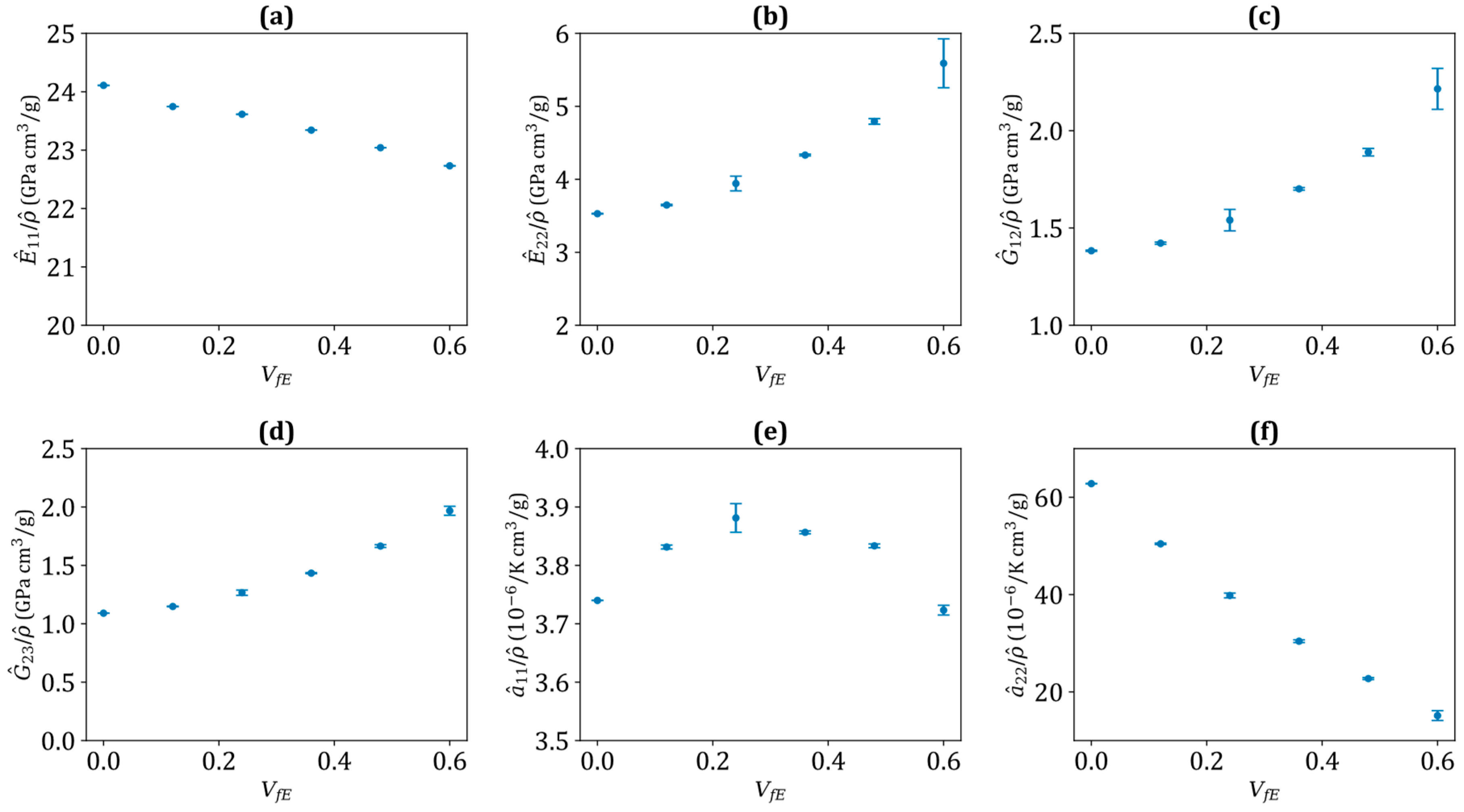
3.1. Homogenised Thermomechanical Properties of the Hybrid Yarn

The literature currently lacks empirical data regarding the elastic properties of flax/E-glass yarns, but existing analytical models can verify the homogenised properties of single-fibre yarn. Figure 3 presents a comparative analysis of the error percentage in predicting the homogenised thermomechanical properties of flax and E-glass yarn obtained from various analytical models [36,37,38,53,54] and the present RVE model. The results indicate a high level of consistency between the microscale RVE model and the analytical models, particularly in the longitudinal moduli and CTEs of the yarns. For flax yarn, the Halpin-Tsai model [53] predicts all five mesoscopic homogenised properties within a 1.3% maximum relative difference, while the Hashin model [37] achieves a 0.9% difference in CTEs. However, the Schapery model [36] significantly overestimates transverse CTE ( α ^ 22 ). Conversely, for E-glass yarn, the Chamis model [38] predicts all five properties with a maximum relative difference of 13.5%, while CTEs show a 15.6% difference from the RVE model. The comparisons reveal minor differences in predicted longitudinal CTEs between the microscale RVE model and the analytical models, but significant differences in transverse CTEs. The difference between analytical models and the microscale model is more pronounced in pure E-glass yarn than in pure flax yarn, possibly due to similarities in transverse modulus, shear modulus, and CTEs between flax yarn and the matrix.
Homogenised thermomechanical properties of hybrid yarns were determined based on five microstructures generated for each combination of fibre volume fraction ratios. Table 3 presents these properties, showing that increasing the E-glass volume fraction ( V f E ) significantly enhances both longitudinal ( E ^ 11 ) and transverse modulus ( E ^ 22 ), indicating greater structural stiffness. The shear moduli ( G ^ 12 and G ^ 23 ) also rise, suggesting improved shear stiffness. The transverse CTEs ( α ^ 22 and α ^ 33 ) in these hybrid yarns exceed their longitudinal CTE ( α ^ 11 ). This difference arises from the diverse transverse CTEs of the constituents, where both the matrix and flax fibre exhibit higher transverse CTEs than E-glass fibre. While the longitudinal CTE increases slightly, the transverse CTEs decrease significantly, indicating enhanced thermal dimensional stability with higher E-glass fibre content. The transverse CTEs were nearly identical, confirming the transversely isotropic nature of the hybrid yarns. However, α ^ 22 and α ^ 33 differ more in pure E-glass yarn than in other volume fraction combinations. Increasing V f E leads to a substantial decrease in transverse CTEs, while longitudinal CTEs slightly increase, but this trend levels off when V f E exceeds 0.4. This suggests that E-glass fibre volume fraction has a more significant influence on transverse CTEs due to the high longitudinal stiffness of E-glass fibres. During thermal cooling, fibres exert tensile stress along the matrix, leading to pronounced transverse contraction and an elevated transverse CTE. While adding E-glass fibres enhances the thermal stability of the hybrid yarn, this improvement is accompanied by an increase in density and reduced biodegradability. The higher density may limit use in aerospace and automotive applications where lightweight structures are critical. Additionally, the poor biodegradability of E-glass fibres raises environmental concerns, particularly for applications requiring sustainable end-of-life management. Therefore, balancing performance and ecological sustainability is essential for specific applications.
Figure 4 presents specific mesoscopic homogenised properties of impregnated hybrid yarn as a function of the E-glass fibre volume fraction ( V f E ), derived from the microscale RVE model. In Figure 4a, the specific longitudinal modulus slightly decreases as the E-glass fibre content increases. Conversely, in Figure 4b–d, specific transverse modulus and specific shear moduli increase with higher E-glass fibre content. The specific longitudinal CTE (Figure 4e) shows a negative parabolic relationship for the specific longitudinal CTE, peaking at a V f E of about 0.20. Figure 4f reveals a significant decrease in specific transverse CTEs, indicating that E-glass fibres effectively restrict thermal expansion in the transverse direction. These results highlight the anisotropic thermal properties of hybrid yarns. Thus, the microscale RVE model accurately predicts the specific mesoscopic homogenised properties of the hybrid yarn.

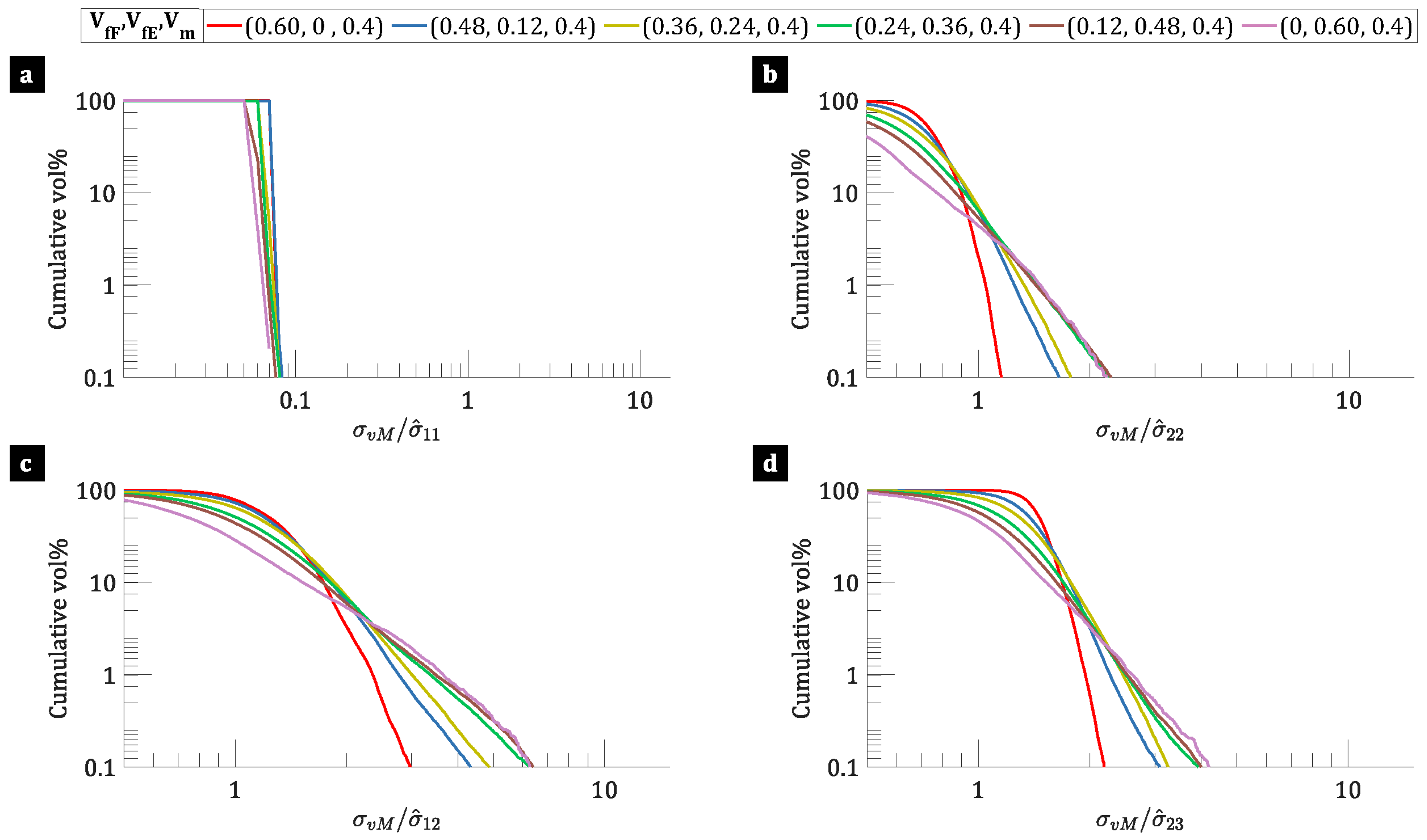
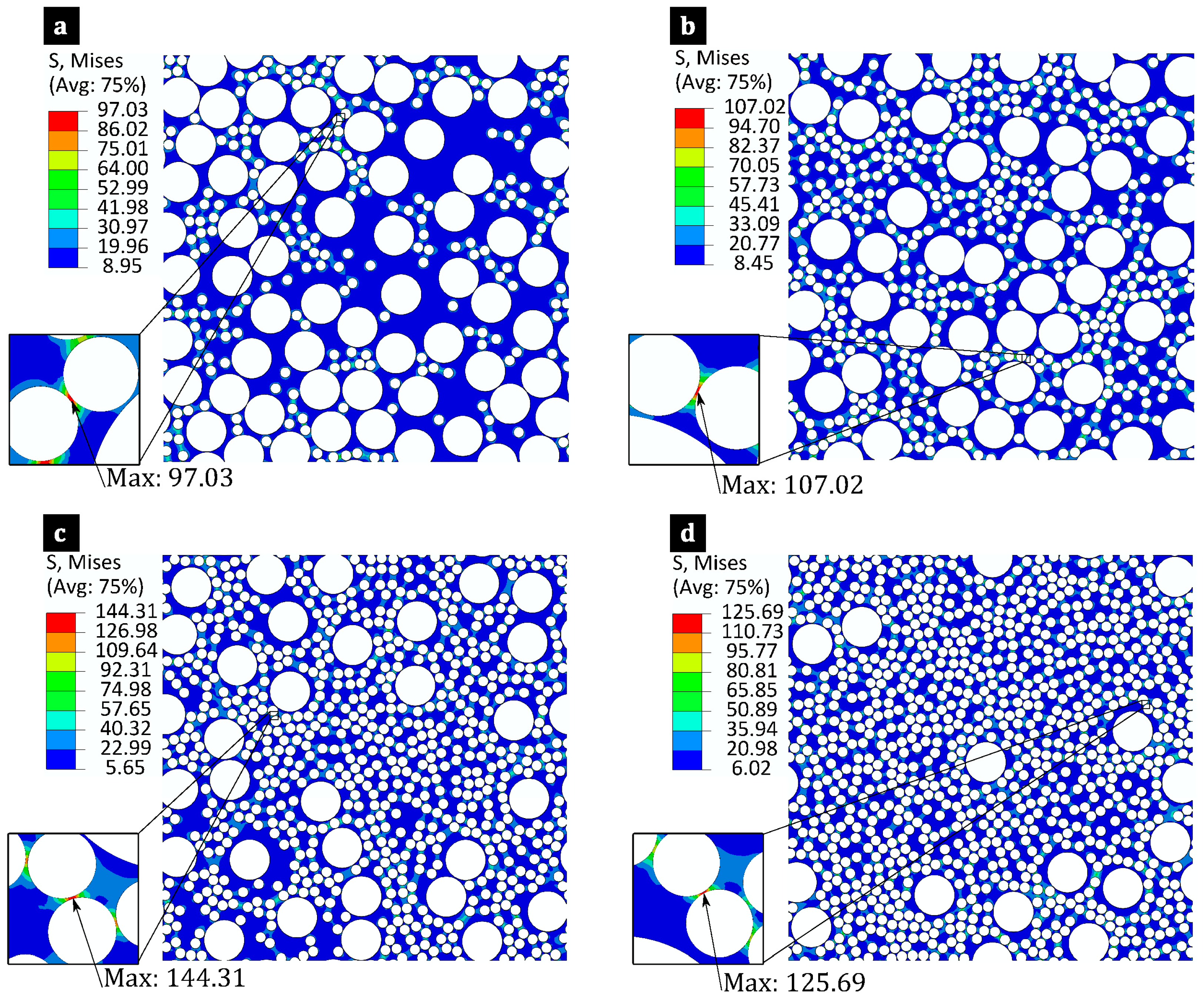
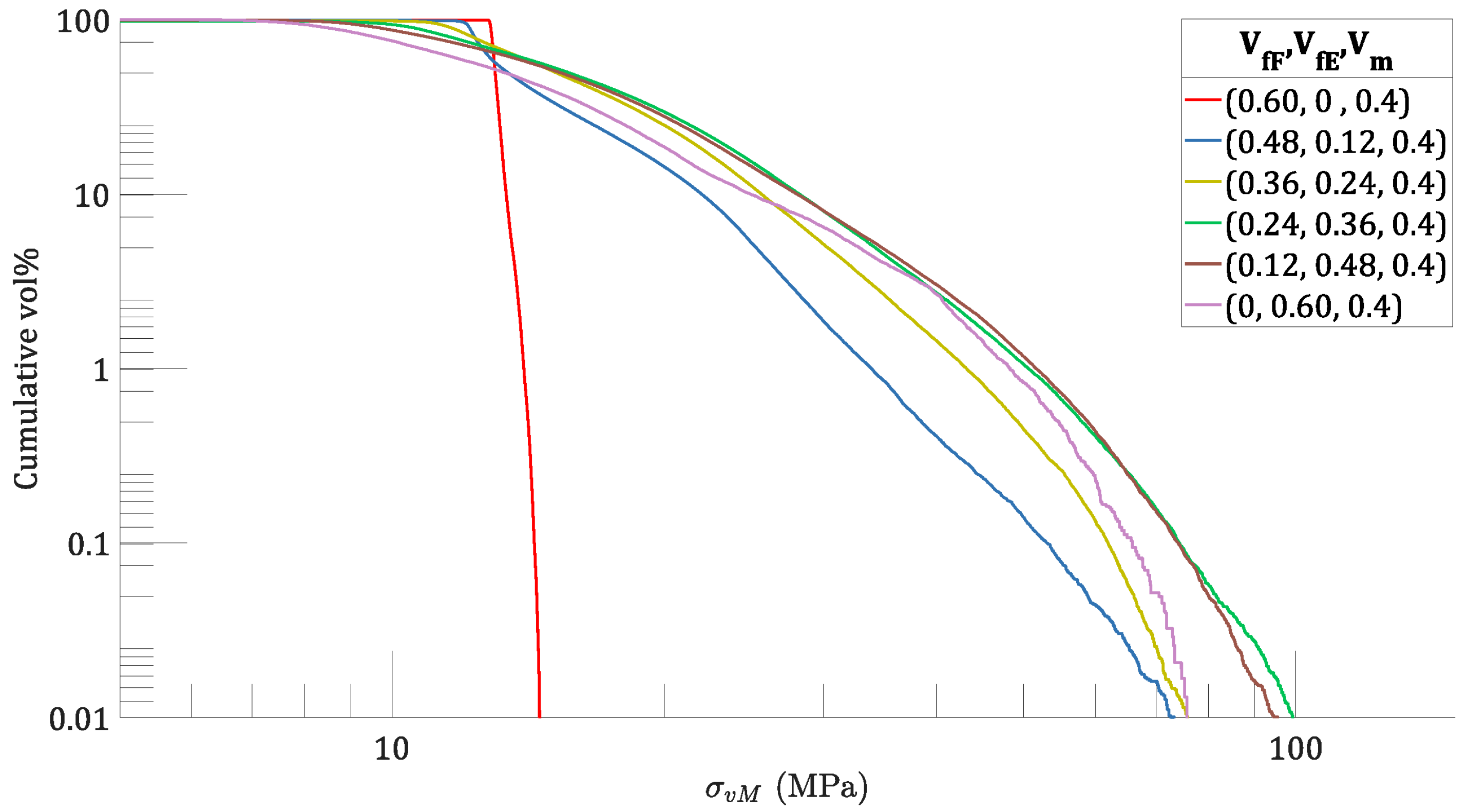
3.2. Micro-Stress in the Hybrid Yarn

Matrix failure is the primary failure mode in composite materials, driven by the micro-stress distribution within the yarns. Although a comprehensive failure analysis is ideal, this study simplifies the analysis by focusing on how hybridisation affects matrix von Mises stress. The stress values are extracted at the integration point of the elements. Figure 5 shows the typical von Mises matrix stress distribution of a microscale RVE of yarn with constituents: V f F ,   V f E ,   V m = 0.48 ,   0.12 ,   0.4 under different mechanical loading cases. The visuals highlight stress concentrations in the matrix, excluding the fibres. High stress gradients are observed around E-glass fibres due to their contrasting material properties, while lower gradients are seen around flax fibres due to their lower elastic properties. The highest von Mises matrix stresses—3.19 MPa under transverse tensile ( σ ˆ 22 ), 8.38 MPa under longitudinal shear ( σ ˆ 12 ), and 6.00 MPa under transverse shear ( σ ˆ 23 )—occur in regions where E-glass fibres are closely spaced. Although the E-glass fibres experience higher stress than the matrix, their inclusion significantly increases the von Mises matrix stress, shifting the failure mode from fibre-driven to matrix-driven failure.
To understand the role of yarn-level fibre hybridisation in stress amplification, Figure 6 presents the relationship between the reverse cumulative volumetric percentage of the matrix and the von Mises stress amplification factor (SAF). This analysis includes yarns with different fibre volume ratios under varying mechanical loading conditions. The SAF represents the ratio between the von Mises stress and the applied load (i.e., the meso stress). Logarithmic scales are employed for better visualisation of matrix volumetric percentages at higher SAF levels. Each curve represents a unique combination of fibre volume fraction ratios, showing minimal deviation across the five microstructures. This consistency indicates statistically similar microstructures, confirming the accuracy of the RVE size chosen. In pure flax yarn, the SAF within the matrix is consistently lower across all mechanical loading cases. However, after incorporating E-glass fibre into the yarn, the SAF in the matrix increased marginally. This rise is due to localised stress concentrations in the matrix, particularly in regions where two high-stiffness E-glass fibres are in close proximity. As a result, hybridisation at the yarn level significantly affects the micro-stress distribution within the matrix, making early matrix failure more likely. This may improve the damage tolerance of the composite materials, as matrix failure often does not lead to the catastrophic collapse of laminated composite structures. However, this hybrid composite material may reduce the specific homogenised properties.
The RVEs exhibit similar thermal residual von Mises stress (TRS) distributions across different microstructures with the same fibre volume fraction ratios. Figure 7 presents typical matrix TRS distributions for flax/E-glass/epoxy composites at four different volume fractions, cooled from 100   ° C to 20   ° C ( Δ T = 80   ° C ). Residual stresses arise after cooling, with the maximum von Mises stress increasing from 97 MPa in (a) to 144 MPa in (c), then slightly decreasing to 126 MPa in (d). This increase is due to higher E-glass fibre content significantly restricting matrix shrinkage, leading to increased TRS. Stress concentrations occur around closely spaced E-glass fibres due to their higher stiffness compared to flax fibres, making these regions potential crack initiation sites. Given that the typical tensile strength of the epoxy matrix is around 100 MPa, stress-based failure criteria such as the maximum stress criterion would predict matrix cracking in microstructures (c) and (d). The results indicate that higher E-glass fibre content increases residual stress within the matrix, due to the greater thermal mismatch between the E-glass fibres and the matrix. Furthermore, in such composites, fibre/matrix interfaces often experience elevated stress levels, making them probable sites for initial crack formation, as opposed to failure solely within the matrix.
To analyse how yarn-level fibre hybridisation influences the TRS in hybrid yarns, the reverse cumulative volumetric percentage of matrix against TRS for yarns with varying fibre volume ratios subjected to thermal loading ( Δ T = 80   ° C ) is presented in Figure 8. The findings indicate that the distribution of TRS varies with the fibre volume ratios. In pure flax yarns, the curve shows a sudden drop at TRS of around 15 MPa, indicating a more uniform distribution of TRS. In contrast, when E-glass fibres are incorporated into the hybrid yarns, the decline in TRS is more gradual, suggesting a higher stress gradient within the matrix. Moreover, a slight increase in cumulative volume percentage at higher stress levels implies increased stress concentrations within the matrix. This analysis shows that yarn-level fibre hybridisation influences TRS distribution within the matrix, with higher E-glass fibre content leading to an increased TRS distribution within the matrix.

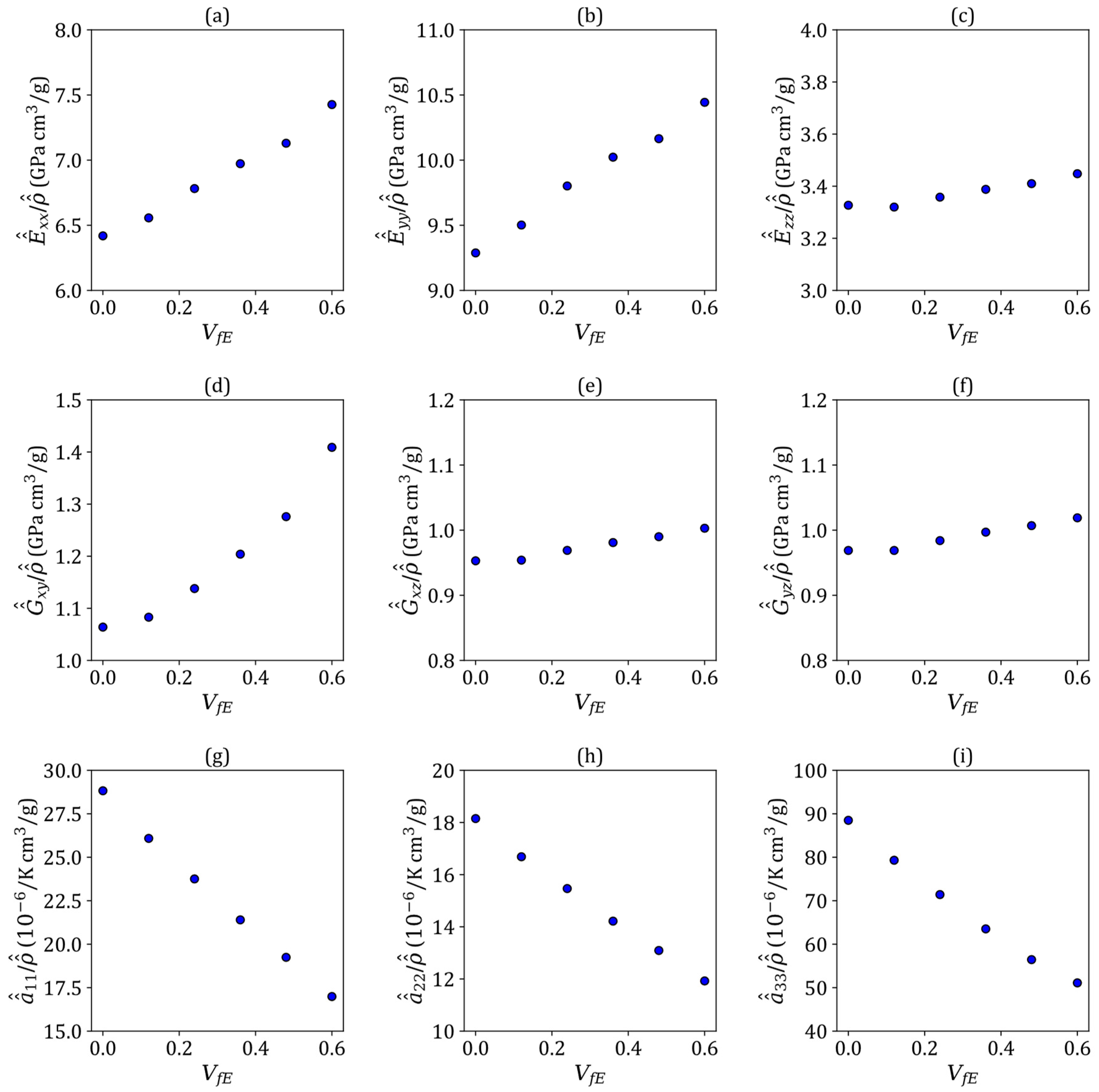
3.3. Homogenised Thermomechanical Properties of the 3D Woven Fabrics

Table 4 compares the experimentally measured and RUC model-predicted thermomechanical properties of E-glass/epoxy plain weave composites. Although the geometry modelled in the RUC approach does not precisely replicate the microstructure used in [55], it still shows a strong correlation with experimental results. The predicted in-plane Young’s modulus and the Poisson’s ratio align closely with experimental results. While there is no available experimental data for the out-of-plane Young’s modulus for direct comparison, the predicted CTEs are consistent with experimental values, despite some small differences. Thus, the RUC model is verified as a reliable tool for predicting the homogenised properties of these composites.
To investigate the thermomechanical behaviour of 3D orthogonal-woven flax/E-glass hybrid composite laminae, the mesoscale RUC model is employed, incorporating yarn-level properties derived from the microscale RVE model. Table 5 and Table 6 show the macroscopic homogenised thermomechanical properties and densities of these composites with different levels of yarn-level fibre hybridisation. Increasing the E-glass fibre volume fraction while reducing flax fibre content leads to a consistent rise in Young’s moduli ( E ^ ^ x x , E ^ ^ y y , E ^ ^ z z ) and shear moduli ( G ^ ^ x y , G ^ ^ x z , G ^ ^ y z ). This trend highlights the superior stiffness of E-glass fibres compared to flax fibres. The Poisson’s ratios show minor variations, suggesting consistent deformation behaviour despite varying volume fraction ratios within the hybrid yarns. The limited contribution of Z-binder yarn in the Z-direction results in lower in-plane Poisson’s ratios ( ν ^ ^ x y , ν ^ ^ x z ) compared to the out-of-plane Poisson’s ratio ( ν ^ ^ y z ), reducing stiffness in the out-of-plane direction. Moreover, the CTEs decrease as the E-glass fibre content increases, indicating better thermal dimensional stability since E-glass fibres have lower CTEs than flax fibres. This stability is essential for applications exposed to temperature fluctuations. The in-plane CTEs ( α ^ ^ x x , α ^ ^ y y ) are lower than the out-of-plane CTE ( α ^ ^ z z ) due to greater fibre yarn contributions in the weft and warp directions. Higher E-glass fibre content improves thermomechanical properties and reduces CTEs but increases the density ( ρ ^ ^ ) of the composite. Therefore, designing hybrid composites demands a careful trade-off among mechanical performance, thermal stability, and density, particularly in weight-sensitive and thermally demanding environments.
Figure 9 shows how the macroscopic properties of 3D orthogonal-woven hybrid composite laminae vary with the E-glass fibre volume fraction ( V f E ) in the hybrid yarn. When normalised by density ( ρ ^ ^ ), these properties reveal significant trends and insights. Figure 9a–c show a consistent increase in specific in-plane moduli with higher V f E , while the specific out-of-plane modulus ( E ^ ^ z z ) remains stable due to the in-plane orientation of the fibre yarns. Similarly, Figure 9d–f, show that the specific in-plane shear modulus ( G ^ ^ x y ) increases with higher V f E , indicating improved in-plane shear stiffness. In contrast, the specific out-of-plane shear moduli ( G ^ ^ x z , G ^ ^ y z ) remain relatively unaffected by variation in E-glass fibre content. Furthermore, Figure 9g–i shows that the specific CTEs decrease with increasing V f E , indicating improved thermal stability per unit mass. This trend is particularly significant for the out-of-plane CTE ( α ^ ^ z z ), which decreases significantly along the z-direction with higher E-glass fibre content. As a result, increasing V f E in hybrid yarns enhances the specific thermomechanical properties of the composite laminae, which are crucial for applications where weight, mechanical performance, and thermal stability are critical.

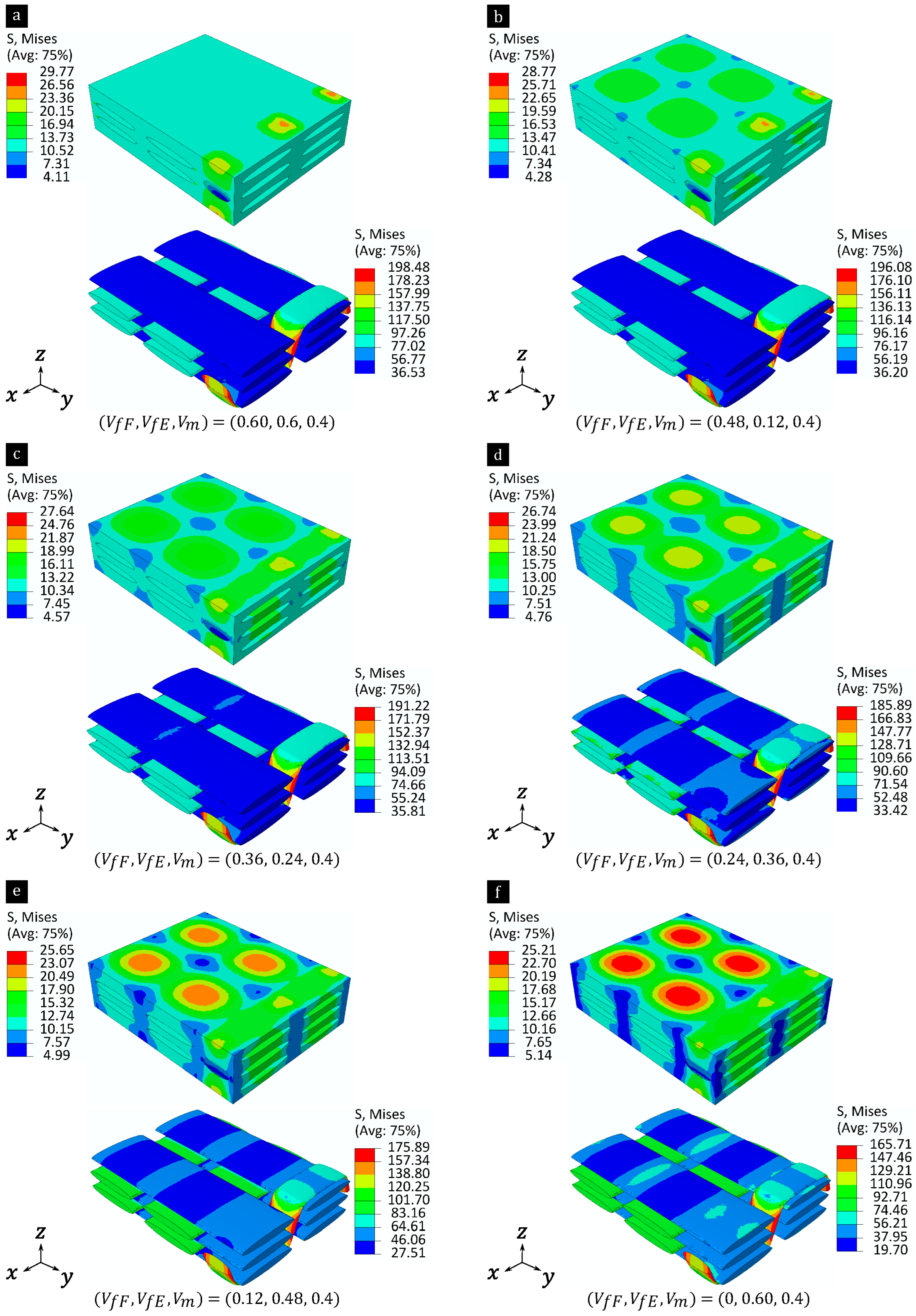
3.4. Meso-Stress in the Woven Fabrics

Figure 10 presents the von Mises stress distributions within both matrix-rich regions and yarns in 3D orthogonal-woven hybrid composite laminae reinforced with E-glass and flax fibres. The analysis assumes a yarn volume fraction ratio of V f F ,   V f E ,   V m = 0.48 ,   0.12 ,   0.4 under various mechanical loading cases. The stress levels in the matrix and yarns are represented with separate legends. While von Mises stress provides insights into stress concentration in matrix-rich regions, its relevance to transversely oriented materials like yarns is limited. Nevertheless, it is used here to quantify stress concentration in yarns. Under in-plane tensile loading, matrix-rich regions experience stresses below 1   M P a , while the warp or weft yarns primarily bear the load depending on the loading direction. Out-of-plane loading results in stress concentration ( ~ 1.18   M P a ) in matrix-rich regions near binder yarn, and stress concentration ( ~ 4.84   M P a ) in binder yarns when the yarn path is vertically upwards. Shear loadings show a different behaviour, with matrix-rich regions showing stresses exceeding 1   M P a , indicating a predominant influence of matrix shear properties on composite shear responses. Additionally, stress fields show shear stress concentrations, particularly at the intersections of weft yarns with binder yarns under σ ^ ^ x y and σ ^ ^ y z loading cases. Moreover, binder yarn exhibits significant stress concentration, with maximum von Mises stress reaching 8.71   M P a under the σ ^ ^ x y loading case, due to complex interactions between binder yarns and adjacent weft yarns.
To examine how yarn-level fibre hybridisation affects stress amplification in composite laminae, Figure 11 presents the reverse cumulative volume percentage of matrix-rich regions against the stress amplification factor (SAF) under different yarn-level fibre hybridisations. For the out-of-plane loading case ( σ ^ ^ z z ), the curves indicate that a higher E-glass fibre content leads to a lower proportion of matrix-rich regions with SAF > 1. Conversely, for shear loading, the curves shift to the right, indicating an increase in the proportion of matrix-rich regions experiencing higher SAF values as E-glass fibre content increases. Specifically, under the in-plane shear loading case ( σ ^ ^ x y ), the curves show a gradual decline in the cumulative volume percentage of matrix-rich regions with increasing SAF, indicating a non-uniform stress distribution. However, for out-of-plane shear loading cases ( σ ^ ^ x z and σ ^ ^ y z ), the curves exhibit a steeper decline, suggesting a more uniform stress distribution. Maximum SAF values range from two to three in some matrix regions, indicating potential stress concentrations and localised failures under shear loadings if the matrix is not sufficiently robust. This highlights the significant influence of fibre hybridisation at the yarn level on stress distribution within matrix-dominated mesoscale regions.
Figure 12 shows the thermal residual von Mises stress (TRS) distribution within the yarns and matrix-rich regions of a mesomechanical RUC model for 3D orthogonal-woven flax/E-glass hybrid composite laminae This distribution is observed after a uniform temperature decrease of 80   ° C , with varying degrees of yarn-level fibre hybridisation. The TRS distribution changes with the hybridisation ratios. In the composite with pure flax yarns (Figure 12a), the stress in the matrix-rich regions and yarns is higher due to flax yarns having a lower α ^ 11 and higher α ^ 22 than E-glass yarns, leading to higher thermal mismatch stress. As the volume fraction of E-glass fibres in the yarns increases, the TRS decreases in both the matrix-rich regions and the yarns. Specifically, the TRS drops from 29.77 MPa to 25.21 MPa in the matrix and from 198.48 MPa to 165.71 MPa in the yarns, as shown in Figure 12a and Figure 12f, respectively. The highest TRS in the yarn is observed in the binder yarns when the yarn path is oriented vertically upward. Figure 12f, with only E-glass in yarns and no flax fibres, shows the least TRS, highlighting the reduced thermal mismatch stress due to the lower CTEs of E-glass yarns. Hence, the results highlight the significant influence of yarn-level fibre hybridisation on TRS distribution within the composite. The transition from flax to E-glass yarns significantly reduces the TRS, suggesting that tailoring the hybridisation ratio could mitigate adverse TRS and improve composite performance in high-temperature applications.
The reversed cumulative volume percentage of the matrix-rich region is plotted against the TRS for composites with varying degrees of fibre hybridisation at the yarn level under thermal loading ( Δ T = 80 ° C ), as shown in Figure 13. In flax yarn composites, about 95% of the matrix region has a TRS of around 15 MPa, while the remaining 5% exhibit maximum values up to 30 MPa. This suggests that while most of the matrix experiences low stresses, there are localised areas with extremely high stresses that could initiate failure. Increasing the E-glass fibre content reduces the maximum TRS, consistent with the trend shown in Figure 12, where increasing the E-glass fibre volume fraction lowers the maximum TRS. As TRS approaches 25 MPa, the volume percentage of matrix-rich regions with high TRS sharply decreases, indicating a more uniform TRS distribution. E-glass yarns, with their lower CTEs, cause less thermal mismatch stress, resulting in lower TRS. Therefore, yarn-level fibre hybridisation significantly affects TRS distributions in hybrid composites, with increased presence of E-glass in yarns correlating with improved mechanical properties and decreased maximum TRS.

4. Conclusions

A two-scale computational approach was implemented to determine the thermomechanical properties of 3D orthogonal-woven flax/E-glass composite laminae with yarn-level fibre hybridisation. Microscale representative volume element models and mesoscale repeating unit cell models were employed. This study explores the homogenised thermomechanical properties and thermal residual von Mises stress fields at both micro- and mesoscale levels. These findings can be applied with stress-based failure criteria to estimate damage initiation. The model employs simplifying assumptions, including linear elasticity and temperature-independent material properties, to enhance computational efficiency while accurately capturing thermomechanical interactions.
The numerical analysis reveals several key findings: (a) Incorporating E-glass fibres improves the hybrid yarn’s elastic properties and thermal stability but increases its density. (b) However, this addition also intensifies thermal residual stress in the matrix due to the greater thermal mismatch between the fibres and the epoxy resin. (c) Integrating E-glass fibres into yarns improves thermomechanical properties and diminishes coefficients of thermal expansions, while simultaneously increasing composite density. (d) Yarn-level fibre hybridisation significantly influences the distribution of thermal residual stress, with a higher E-glass content leading to improved mechanical properties and reduced maximum residual stress.
Overall, the study demonstrates that yarn-level fibre hybridisation in 3D orthogonal-woven flax/E-glass composites enhances mechanical properties, improves thermal stability, and reduces thermal residual stresses. This approach provides a tailored balance between performance and density, making these composites suitable for high-temperature and structural applications. Future work could focus on experimental thermomechanical testing to validate the assumptions made in the RVE and RUC models presented in this study.

Author Contributions

Conceptualisation, N.Y., Z.Z. and K.B.K.; methodology, N.Y.; formal analysis, N.Y.; investigation, N.Y.; data curation, N.Y.; writing—original draft preparation, N.Y.; writing—review and editing, Z.Z., C.S., P.P. and K.B.K.; visualization, N.Y.; supervision, Z.Z., P.P. and K.B.K.; funding acquisition, K.B.K. All authors have read and agreed to the published version of the manuscript.

Funding

This research was funded by EPSRC [Grant: EP/T517823/1] and the APC was funded by the University of Manchester [APC ID: 615015].

Data Availability Statement

Dataset available on request from the authors.

Acknowledgments

The authors acknowledge funding from the University of Manchester and EPSRC [Grant EP/T517823/1] and access to the University’s Computer Shared Facility 3.

Conflicts of Interest

The authors declare no conflict of interest.

References

  1. Pickering, K.L.; Efendy, M.G.A.; Le, T.M. A review of recent developments in natural fibre composites and their mechanical performance. Compos. Part A Appl. Sci. Manuf. 2016, 83, 98–112. [Google Scholar] [CrossRef]
  2. Sathishkumar, T.; Navaneethakrishnan, P.; Shankar, S.; Rajasekar, R.; Rajini, N. Characterization of natural fiber and composites—A review. J. Reinf. Plast. Compos. 2013, 32, 1457–1476. [Google Scholar] [CrossRef]
  3. Gupta, M.K.; Ramesh, M.; Thomas, S. Effect of hybridization on properties of natural and synthetic fiber-reinforced polymer composites (2001–2020): A review. Polym. Compos. 2021, 42, 4981–5010. [Google Scholar] [CrossRef]
  4. Nurazzi, N.M.; Asyraf, M.R.M.; Fatimah Athiyah, S.; Shazleen, S.S.; Rafiqah, S.A.; Harussani, M.M.; Kamarudin, S.H.; Razman, M.R.; Rahmah, M.; Zainudin, E.S.; et al. A Review on Mechanical Performance of Hybrid Natural Fiber Polymer Composites for Structural Applications. Polymers 2021, 13, 2170. [Google Scholar] [CrossRef]
  5. Ismail, S.O.; Akpan, E.; Dhakal, H.N. Review on natural plant fibres and their hybrid composites for structural applications: Recent trends and future perspectives. Compos. Part C Open Access 2022, 9, 100322. [Google Scholar] [CrossRef]
  6. Mohd Bakhori, S.N.; Hassan, M.Z.; Mohd Bakhori, N.; Jamaludin, K.R.; Ramlie, F.; Md Daud, M.Y.; Abdul Aziz, S.A. Physical, Mechanical and Perforation Resistance of Natural-Synthetic Fiber Interply Laminate Hybrid Composites. Polymers 2022, 14, 1322. [Google Scholar] [CrossRef]
  7. Jin, K.K.; Oh, J.H.; Ha, S.K. Effect of Fiber Arrangement on Residual Thermal Stress Distributions in a Unidirectional Composite. J. Compos. Mater. 2007, 41, 591–611. [Google Scholar] [CrossRef]
  8. Huang, S.; Zhang, J.; Gu, B.; Sun, B. In-situ characterization and multiscale finite element analyses for thermomechanical behavior of 3D woven composites. Compos. Sci. Technol. 2023, 233, 109906. [Google Scholar] [CrossRef]
  9. Zhao, L.G.; Warrior, N.A.; Long, A.C. A micromechanical study of residual stress and its effect on transverse failure in polymer–matrix composites. Int. J. Solids Struct. 2006, 43, 5449–5467. [Google Scholar] [CrossRef]
  10. Safarabadi, M.; Shokrieh, M.M. Understanding residual stresses in polymer matrix composites. In Residual Stresses in Composite Materials; Elsevier: Amsterdam, The Netherlands, 2014; pp. 197–232. [Google Scholar]
  11. Lu, C.; Chen, P.; Yu, Q.; Gao, J.; Yu, B. Thermal Residual Stress Distribution in Carbon Fiber/Novel Thermal Plastic Composite. Appl. Compos. Mater. 2008, 15, 157–169. [Google Scholar] [CrossRef]
  12. Dhiman, S.; Potluri, P.; Katnam, K.B. Thermally induced residual stresses in orthogonal 3D woven composites: The role of binder architecture and cooling rate. In Proceedings of the AIAA SCITECH 2022 Forum: American Institute of Aeronautics and Astronautics, San Diego, CA, USA, 3–7 January 2022. [Google Scholar]
  13. Hui, X.; Xu, Y.; Wang, J.; Zhang, W. Microscale viscoplastic analysis of unidirectional CFRP composites under the influence of curing process. Compos. Struct. 2021, 266, 113786. [Google Scholar] [CrossRef]
  14. Yuan, Z.; Wang, Y.; Yang, G.; Tang, A.; Yang, Z.; Li, S.; Li, Y.; Song, D. Evolution of curing residual stresses in composite using multi-scale method. Compos. Part B Eng. 2018, 155, 49–61. [Google Scholar] [CrossRef]
  15. Zobeiry, N.; Poursartip, A. 3—The origins of residual stress and its evaluation in composite materials. In Structural Integrity and Durability of Advanced Composites; Woodhead Publishing: Cambridge, UK, 2015; pp. 43–72. [Google Scholar]
  16. Karadeniz, Z.H.; Kumlutas, D. A numerical study on the coefficients of thermal expansion of fiber reinforced composite materials. Compos. Struct. 2007, 78, 1–10. [Google Scholar] [CrossRef]
  17. Yang, L.; Yan, Y.; Ma, J.; Liu, B. Effects of inter-fiber spacing and thermal residual stress on transverse failure of fiber-reinforced polymer–matrix composites. Comput. Mater. Sci. 2013, 68, 255–262. [Google Scholar] [CrossRef]
  18. Chen, Y.; Xia, Z.; Ellyin, F. Evolution of residual stresses induced during curing processing using a viscoelastic micromechanical model. J. Compos. Mater. 2001, 35, 522–542. [Google Scholar] [CrossRef]
  19. Zhao, L.G.; Warrior, N.A.; Long, A.C. A thermo-viscoelastic analysis of process-induced residual stress in fibre-reinforced polymer–matrix composites. Mater. Sci. Eng. A 2007, 452–453, 483–498. [Google Scholar] [CrossRef]
  20. Maligno, A.R.; Warrior, N.A.; Long, A.C. Finite element investigations on the microstructure of fibre-reinforced composites. Express Polym. Lett. 2008, 2, 665–676. [Google Scholar] [CrossRef]
  21. Maligno, A.R.; Warrior, N.A.; Long, A.C. Effects of inter-fibre spacing on damage evolution in unidirectional (UD) fibre-reinforced composites. Eur. J. Mech. A/Solids 2009, 28, 768–776. [Google Scholar] [CrossRef]
  22. Hui, X.; Xu, Y.; Zhang, W. Multiscale model of micro curing residual stress evolution in carbon fiber-reinforced thermoset polymer composites. Front. Mech. Eng. 2020, 15, 475–483. [Google Scholar] [CrossRef]
  23. Wang, M.; Hang, X. Finite Element Analysis of Residual Stress Distribution Patterns of Prestressed Composites Considering Interphases. Materials 2023, 16, 1345. [Google Scholar] [CrossRef]
  24. Fletcher, A.J.; Oakeshott, J.L. Thermal residual microstress generation during the processing of unidirectional carbon fibre/epoxy resin composites: Random fibre arrays. Composites 1994, 25, 806–813. [Google Scholar] [CrossRef]
  25. González, C.; Llorca, J. Mechanical behavior of unidirectional fiber-reinforced polymers under transverse compression: Microscopic mechanisms and modeling. Compos. Sci. Technol. 2007, 67, 2795–2806. [Google Scholar] [CrossRef]
  26. McLendon, W.R.; Whitcomb, J.D. Influence of thermally induced microstress and microstructural randomness on transverse strength of unidirectional composites. J. Compos. Mater. 2015, 50, 1467–1481. [Google Scholar] [CrossRef]
  27. He, J.; Cui, X.; Lua, J.; Liu, L. Interplay of manufacturing-induced thermal residual stresses and microvoids in damage and failure of fiber-reinforced composites. Int. J. Mech. Sci. 2023, 242, 108000. [Google Scholar] [CrossRef]
  28. Zhang, F.; Ye, Y.; Li, M.; Wang, H.; Cheng, L.; Wang, Q.; Ke, Y. Computational modeling of micro curing residual stress evolution and out-of-plane tensile damage behavior in fiber-reinforced composites. Compos. Struct. 2023, 322, 117370. [Google Scholar] [CrossRef]
  29. Parameswaranpillai, J.; Krishnasamy, S.; Siengchin, S.; Radoor, S.; Joy, R.; George, J.J.; Muthukumar, C.; Muthukumar, S.M.K.; Salim, N.V.; Hameed, N.; et al. Thermal Properties of the Natural Fiber-Reinforced Hybrid Polymer Composites: An Overview. In Natural Fiber-Reinforced Composites; Wiley-VCH: Hoboken, NJ, USA, 2022; pp. 31–51. [Google Scholar]
  30. Vinod, A.; Gowda, Y.; Krishnasamy, S.; Sanjay, M.R.; Siengchin, S. Thermal Properties of Hybrid Natural Fiber-Reinforced Thermoplastic Composites. In Natural Fiber-Reinforced Composites; Wiley-VCH: Hoboken, NJ, USA, 2022; pp. 17–30. [Google Scholar]
  31. Yang, N.; Zou, Z.; Potluri, P.; Soutis, C.; Katnam, K.B. Intra-yarn fibre hybridisation effect on homogenised elastic properties and micro and meso-stress analysis of 2D woven laminae: Two-scale FE model. Compos. Struct. 2024, 344, 118358. [Google Scholar] [CrossRef]
  32. Li, S.; Sitnikova, E. Representative Volume Elements and Unit Cells: Concepts, Theory, Applications and Implementation; Woodhead Publishing: Cambridge, UK, 2019. [Google Scholar]
  33. Gentles, F.; Anderson, J.; Thomason, J.L. Characterisation of the transverse thermoelastic properties of natural fibres used in composites. In Proceedings of the 14th European Conference on Composite Materials, ECCM14, Budapest, Hungary, 7–10 June 2010. [Google Scholar]
  34. Thomason, J.; Yang, L.; Gentles, F. Characterisation of the Anisotropic Thermoelastic Properties of Natural Fibres for Composite Reinforcement. Fibers 2017, 5, 36. [Google Scholar] [CrossRef]
  35. Saidane, E.H.; Scida, D.; Ayad, R. Thermo-mechanical behaviour of flax/green epoxy composites: Evaluation of thermal expansion coefficients and application to internal stress calculation. Ind. Crops Prod. 2021, 170, 113786. [Google Scholar] [CrossRef]
  36. Schapery, R.A. Thermal Expansion Coefficients of Composite Materials Based on Energy Principles. J. Compos. Mater. 1968, 2, 380–404. [Google Scholar] [CrossRef]
  37. Hashin, Z. Analysis of Properties of Fiber Composites With Anisotropic Constituents. J. Appl. Mech. 1979, 46, 543–550. [Google Scholar] [CrossRef]
  38. Chamis, C.C. Simplified composite micromechanics equations for hygral, thermal and mechanical properties. In Proceedings of the SAMPE Quarterly: Ann. Conf. of the Society of the Plastics Industry (SPI) Reinforced Plastics/Composites Inst, Houston, TX, USA, 7–11 February 1984; pp. 14–23. [Google Scholar]
  39. Trias, D.; Costa, J.; Turon, A.; Hurtado, J. Determination of the critical size of a statistical representative volume element (SRVE) for carbon reinforced polymers☆. Acta Mater. 2006, 54, 3471–3484. [Google Scholar] [CrossRef]
  40. Yang, L.; Yan, Y.; Ran, Z.; Liu, Y. A new method for generating random fibre distributions for fibre reinforced composites. Compos. Sci. Technol. 2013, 76, 14–20. [Google Scholar] [CrossRef]
  41. Melro, A.R.; Camanho, P.P.; Pinho, S.T. Influence of geometrical parameters on the elastic response of unidirectional composite materials. Compos. Struct. 2012, 94, 3223–3231. [Google Scholar] [CrossRef]
  42. Li, Y.; Zhou, L.; Zhang, M.; Song, C. Study on the Effect of Void Defect on Mechanical Properties of Carbon Fiber Composites by Finite Element Method. J. Inst. Eng. Ser. C 2022, 103, 1433–1446. [Google Scholar] [CrossRef]
  43. Vallmajó, O.; Arteiro, A.; Guerrero, J.M.; Melro, A.R.; Pupurs, A.; Turon, A. Micromechanical analysis of composite materials considering material variability and microvoids. Int. J. Mech. Sci. 2023, 263, 108781. [Google Scholar] [CrossRef]
  44. Smith, M. ABAQUS/Standard User’s Manual; Dassault Systèmes Simulia Corp: Johnston, RI, USA, 2009. [Google Scholar]
  45. Brown, L.P.; Long, A.C. Modeling the geometry of textile reinforcements for composites: TexGen. In Composite Reinforcements for Optimum Performance; Elsevier: Amsterdam, The Netherlands, 2021; pp. 237–265. [Google Scholar]
  46. Sherburn, M. Geometric and Mechanical Modelling of Textiles; University of Nottingham: Nottingham, UK, 2007. [Google Scholar]
  47. Scida, D.; Aboura, Z.; Benzeggagh, M.L.; Bocherens, E. A micromechanics model for 3D elasticity and failure of woven-fibre composite materials. Compos. Sci. Technol. 1999, 59, 505–517. [Google Scholar] [CrossRef]
  48. Zhong, Y.; Tran, L.Q.N.; Kureemun, U.; Lee, H.P. Prediction of the mechanical behavior of flax polypropylene composites based on multi-scale finite element analysis. J. Mater. Sci. 2017, 52, 4957–4967. [Google Scholar] [CrossRef]
  49. Swolfs, Y.; Verpoest, I.; Gorbatikh, L. Recent advances in fibre-hybrid composites: Materials selection, opportunities and applications. Int. Mater. Rev. 2019, 64, 181–215. [Google Scholar] [CrossRef]
  50. Huntsman. Technical Data Sheet: Araldite LY 564 & Aradur 2954. 2011. Available online: https://files.ekmcdn.com/mouldlife/resources/other/araldite-ly564-aradur-2954-eur-e-1-.pdf (accessed on 6 May 2024).
  51. Li, S.; Jeanmeure, L.F.C.; Pan, Q. A composite material characterisation tool: UnitCells. J. Eng. Math. 2015, 95, 279–293. [Google Scholar] [CrossRef]
  52. Soden, P.D.; Hinton, M.J.; Kaddour, A.S. Chapter 2.1—Lamina properties, lay-up configurations and loading conditions for a range of fibre reinforced composite laminates. In Failure Criteria in Fibre-Reinforced-Polymer Composites; Elsevier: Oxford, UK, 2004; pp. 30–51. [Google Scholar]
  53. Affdl, J.C.H.; Kardos, J.L. The Halpin-Tsai equations: A review. Polym. Eng. Sci. 1976, 16, 344–352. [Google Scholar] [CrossRef]
  54. Mori, T.; Tanaka, K. Average stress in matrix and average elastic energy of materials with misfitting inclusions. Acta Metall. 1973, 21, 571–574. [Google Scholar] [CrossRef]
  55. Dasgupta, A.; Agarwal, R.K.; Bhandarkar, S.M. Three-dimensional modeling of woven-fabric composites for effective thermo-mechanical and thermal properties. Compos. Sci. Technol. 1996, 56, 209–223. [Google Scholar] [CrossRef]
Figure 1. Typical microstructures for the RVE model with different constituents (i.e., volume fraction of flax fibre, E-glass fibre and matrix V f F ,   V f E ,   V m ): (a) (0.60, 0, 0.4), (b) (0.48, 0.12, 0.4), (c) (0.36, 0.24, 0.4), (d) (0.24, 0.36, 0.4), (e) (0.12, 0.48, 0.4), and (f) (0, 0.60, 0.4).
Jcs 09 00135 g001
Figure 2. Mesoscale RUC model—3D orthogonal weave ( u n i t : μ m ).
Jcs 09 00135 g002
Figure 3. Homogenised thermomechanical properties for (a) E-glass yarn and (b) flax yarn, using microscale RVE model and various analytical models [36,37,38,53,54].
Jcs 09 00135 g003
Figure 4. Specific mesoscopic homogenised properties: (a) E ^ 11 , (b) E ^ 22 , (c) G ^ 12 , (d) G ^ 23 , (e) α ^ 11 , and (f) α ^ 22 of impregnated hybrid yarn versus volume fraction of E-glass fibre ( V f E ) using verified microscale RVE model.
Jcs 09 00135 g004
Figure 5. Flax/epoxy lamina von Mises matrix stress distribution for a volume fraction of V f F ,   V f E ,   V m = 0.48 ,   0.12 ,   0.4 , under various mechanical loading cases (unit: M P a ): (a) σ ˆ 11 = 1 , (b) σ ˆ 22 = 1 , (c) σ ˆ 12 = 1 and (d) σ ˆ 23 = 1 .
Jcs 09 00135 g005
Figure 6. The reversed cumulative matrix volume percentage as a function of the von Mises stress amplification factor (SAF), with varying yarn constituents, for four loading cases: (a) σ ˆ 11 , (b) σ ˆ 22 , (c) σ ˆ 12 , and (d) σ ˆ 23 .
Jcs 09 00135 g006
Figure 7. The thermal residual von Mises matrix stress distributions (unit: MPa) of the flax/E-glass/epoxy laminae under thermal loading ( Δ T = 80   ° C ) with volume fraction V f F , V f E ,   V m : (a) (0.48, 0.12, 0.4), (b) (0.36, 0.24, 0.4), (c) (0.24, 0.36, 0.4), and (d) (0.12, 0.48, 0.4).
Jcs 09 00135 g007
Figure 8. The reverse cumulative matrix volume percentage as a function of thermal residual von Mises stress for yarns with different constituents under thermal loading ( Δ T = 80   ° C ).
Jcs 09 00135 g008
Figure 9. Specific macroscopic homogenised properties: (a) E ^ ^ x x , (b) E ^ ^ y y , (c) E ^ ^ z z , (d) G ^ ^ x y , (e) G ^ ^ x z , (f) G ^ ^ y z , (g) α ^ ^ x x , (h) α ^ ^ y y , and (i) α ^ ^ z z of 3D orthogonal-woven hybrid composite laminae versus volume fraction of E-glass fibre ( V f E ) within the hybrid yarn.
Jcs 09 00135 g009
Figure 10. Distribution of von Mises stress fields in the matrix-rich region (top) and yarns (bottom) for the mesomechanical RUC model of 3D orthogonal-woven flax/E-glass hybrid composite laminae with yarn volume fraction ratio V f F , V f E ,   V m   =   0.48,0.12 ,   0.4 , under: (a) σ ^ ^ x x = 1   M P a , (b) σ ^ ^ y y = 1 M P a , (c) σ ^ ^ z z = 1 M P a , (d) σ ^ ^ x y = 1 M P a , (e) σ ^ ^ x z = 1   M P a , and (f) σ ^ ^ y z = 1 M P a .
Jcs 09 00135 g010
Figure 11. Relationship between the reversed cumulative volume percentage of the matrix-rich region and the von Mises stress amplification factor (SAF) in 3D orthogonal-woven flax/E-glass hybrid composite laminae with different yarn-level fibre hybridisation under four loading cases (unit: M P a ): (a) σ ^ ^ z z = 1 , (b) σ ^ ^ x y = 1 , (c) σ ^ ^ x z = 1 , and (d) σ ^ ^ y z = 1 .
Jcs 09 00135 g011
Figure 12. Thermal residual von Mises stress fields (unit: MPa) in the matrix-rich regions (top) and yarns (bottom) of the mesomechanical RUC model for 3D orthogonal-woven flax/E-glass hybrid composite laminae under thermal loading ( Δ T = 80 ° C ), with varying yarn-level fibre hybridisation V f F , V f E ,   V m : (a) (0.60, 0, 0.4), (b) (0.48, 0.12, 0.4), (c) (0.36, 0.24, 0.4), (d) (0.24, 0.36, 0.4), (e) (0.12, 0.48, 0.4), and (f) (0, 0.60, 0.4).
Jcs 09 00135 g012
Figure 13. Reversed cumulative volume percentage of the matrix-rich region plotted against thermal residual von Mises stress for 3D orthogonal-woven flax/E-glass hybrid composites with different yarn-level fibre hybridisation, under thermal loading ( Δ T = 80   ° C ).
Jcs 09 00135 g013
Table 1. The properties of the constituents [33,34,35,47,48,49,50] used in the RVEs.
Constituent E 1
(GPa)
E 2
(GPa)
G 12
(GPa)
G 23
(GPa)
ν 12 ν 23 α 11
( 10 6 / K )
α 22
( 10 6 / K )
Density
( g / c m 3 )
Diameter
( μ m )
E-glass 73 73 30.4 30.4 0.2 0.2 5.4 5.4 2.5 15
Flax 52 7 3 2 0.3 0.75 2.8 79.3 1.4 1.5 58
Epoxy 2.55 2.55 0.94 0.94 0.35 0.35 70 70 1.15
Table 2. Comparison of mesoscopic homogenised thermomechanical properties of E-glass/epoxy lamina based on RVE, experiment results [52], and the Chamis model [38].
LaminaMethod E ^ 11 (GPa) ν ^ 12 E ^ 22 (GPa) G ^ 12 (GPa) G ^ 23 (GPa) α ^ 11
( 10 6 / K )
α ^ 22
( 10 6 / K )
E-glass/epoxyRVE 45.48 0.24 13.60 5.40 4.82 6.9025.10
Experimental 45.60 0.278 16.20 5.83 5.79 8.6026.40
Chamis 45.74 0.26 12.86 4.84 4.84 6.4621.31
Table 3. Mesoscopic homogenised thermomechanical properties for hybrid yarn with varying volume fractions of flax and E-glass fibre and matrix V f F ,   V f E ,   V m , averaged from five different microstructures for each set.
( V f F ,   V f E ,   V m ) E ^ 11
(GPa)
ν ^ 12 E ^ 22
(GPa)
G ^ 12
(GPa)
G ^ 23
(GPa)
α ^ 11
( 10 6 / K )
α ^ 22
( 10 6 / K )
α ^ 33
( 10 6 / K )
ρ ^
( g / c m 3 )
(0.60, 0, 0.4)32.070.324.691.841.454.9783.5383.561.33
(0.48, 0.12, 0.4)34.670.305.332.081.685.5973.6373.011.46
(0.36, 0.24, 0.4)37.310.296.222.432.006.1362.8362.871.58
(0.24, 0.36, 0.4)39.920.277.412.912.456.5952.0252.191.71
(0.12, 0.48, 0.4)42.170.268.773.463.057.0241.6141.571.83
(0, 0.60,0.4)44.550.2410.964.343.867.3029.6632.891.96
Table 4. Homogenised properties of E-glass/epoxy plain weave: Experimental data [55] vs. RUC predictions.
Plain WeaveMethod E ^ ^ x x (GPa) ν ^ ^ x y E ^ ^ z z (GPa) G ^ ^ x y (GPa) G ^ y z (GPa) α ^ ^ x x
( 10 6 / K )
α ^ ^ z z
( 10 6 / K )
E-glass/epoxyRUC 19.13 0.16 9.06 3.32 2.63 18.255.8
Experimental 18.80 0.14 N/AN/AN/A 15.0 58.1
Table 5. Macroscopic homogenised mechanical properties for 3D orthogonal-woven hybrid composite laminae with varying volume fractions of flax and E-glass fibre and matrix V f F ,   V f E ,   V m within the hybrid yarn.
( V f F ,   V f E ,   V m ) E ^ ^ x x
(GPa)
E ^ ^ y y
(GPa)
E ^ ^ z z
(GPa)
G ^ ^ x y
(GPa)
G ^ ^ x z
(GPa)
G ^ ^ y z
(GPa)
ν ^ ^ x y ν ^ ^ x z ν ^ ^ y z
(0.60, 0,0.4)7.9011.424.091.311.171.190.110.500.46
(0.48, 0.12, 0.4)8.4612.264.281.401.231.250.100.490.45
(0.36, 0.24, 0.4)9.0913.144.501.521.301.320.100.480.43
(0.24, 0.36, 0.4)9.7614.034.741.691.371.400.100.460.42
(0.12, 0.48, 0.4)10.4114.844.981.861.451.470.100.440.40
(0, 0.60,0.4)11.2215.775.212.131.511.540.100.420.39
Table 6. Macroscopic homogenised coefficients of thermal expansion (CTEs) and densities for 3D orthogonal-woven hybrid composite laminae with varying volume fractions of flax and E-glass fibre and matrix V f F ,   V f E ,   V m within the hybrid yarn.
( V f F ,   V f E ,   V m ) α ^ ^ x x
( 10 6 / K )
α ^ ^ y y
( 10 6 / K )
α ^ ^ z z
( 10 6 / K )
ρ ^ ^
( g / c m 3 )
(0.60, 0,0.4)35.4522.32108.861.23
(0.48, 0.12, 0.4)33.6521.52102.321.29
(0.36, 0.24, 0.4)31.8320.7395.701.34
(0.24, 0.36, 0.4)29.9619.9088.941.40
(0.12, 0.48, 0.4)28.1019.1282.421.46
(0, 0.60,0.4)25.6618.0177.171.51
Disclaimer/Publisher’s Note: The statements, opinions and data contained in all publications are solely those of the individual author(s) and contributor(s) and not of MDPI and/or the editor(s). MDPI and/or the editor(s) disclaim responsibility for any injury to people or property resulting from any ideas, methods, instructions or products referred to in the content.

