Abstract
The use of 3D printing is expanding in manufacturing wind turbine blades for renewable energy. This study examines the relationship between geometric parameters, mechanical strength, and aerodynamic performance in blades made from short carbon fiber-reinforced PLA (SCFR-PLA) composites. To achieve this, it includes a comparative evaluation of innovative blade designs and materials, aiming to enhance both the energy efficiency and mechanical durability of horizontal axis wind turbines (HAWTs). The numerical model of the wind turbine blade is validated against experimental results, which employed a NACA geometry and ABS polymer. Building upon this validation, a design of experiments (DOE) analysis is employed to explore the influence of fused filament fabrication (FFF) parameters on the mechanical properties of SCFR-PLA composites. A novel blade design, referred to as HAWTSav, is numerically evaluated using 3D-printed SCFR-PLA composites. Numerical simulations are conducted to evaluate the energy efficiency and structural integrity of the HAWTSav blade. A comparative analysis is then performed, contrasting the performance of the conventional NACA blade in ABS with the HAWTSav blade in SCFR-PLA composites. The findings highlight the potential of SCFR-PLA composites in the development of efficient and durable wind turbine blades, highlighting their applicability, particularly in small-scale wind energy systems.
1. Introduction
The energy efficiency and the durability of an energetic system are mainly influenced by factors including component geometry, material strength, and process parameters [1,2,3]. In this context, 2D numerical simulations were conducted on the conventional Savonius rotor, demonstrating its dependence on both blade profile and design parameters [4,5]. Chitura et al. [6] critically assessed various combinations of parametric adjustments aimed at enhancing performance and power output in Savonius wind turbines, which belong to the category of vertical axis wind turbines (VAWTs). Furthermore, horizontal axis wind turbines (HAWTs) are widely preferred due to their higher efficiency than VAWTs. For that, HAWTs are mostly used for generating electricity [7]. Rahman et al. (2018) [8] examined small-scale HAWTs with two, three, and five blades to improve performance. Findings show that three blades increase efficiency, while five blades can sometimes decrease the power coefficient. Vibration analysis of HAWT rotors and shafts using different materials highlighted the importance of material choice in design. Savonius wind turbines, belonging to the category of VAWTs, have been developed in previous studies and their efficiency has been analyzed. Zhao et al. [9] investigated optimal conditions for a multi-blade modified Savonius rotor using various blade configurations to enhance rotor power efficiency. Various sizes of HAWTs exist, including small wind turbines with rotor diameters of 1.25 m or less [10]. These smaller turbines are particularly suitable for generating power in urban environments. In this work, the wind turbine blades were made of ABS polymer. For instance, a scale model of a HAWT was developed and a suitable diffuser was fabricated for wind tunnel experiments [10,11]. They used a novel method to calculate power output across different wind velocities, evaluating performance in terms of the power coefficient. The experimental results were validated against CFD simulations, proving the effectiveness of their approach. Sivamani et al. (2019) [12] conducted a study to analyze the performance characteristics of a HAWT integrated with Savonius blades across a range of wind velocities and loading conditions.
Wind turbine blades were manufactured using a single material. Such blades commonly faced issues of low durability and high failure rates. To address these challenges, composite materials, particularly those using polymer matrices, were introduced as alternates. These composites demonstrated superior performance, significantly enhancing the durability and reliability of turbine blades. Current research and trials continue to focus on improving the aerodynamic performance and environmental properties of polymer composites to further optimize the efficiency of wind turbine blades. The application of fiber-reinforced polymer composites is becoming increasingly prevalent in the wind energy sector due to their excellent strength-to-weight ratio. Glass fiber-reinforced polymers were widely used for durable and efficient turbine blades, while carbon fiber composites are gaining attention for enhanced performance and reduced weight [13,14]. Basalt fiber-reinforced epoxy composites have been also utilized in small-scale wind turbines, offering a promising alternative to traditional materials [15]. Known for their superior mechanical properties compared to E-glass composites, basalt fiber composites provide enhanced strength, durability, and performance of wind turbine blades. Elhenawy et al. (2021) [16] investigated the effect of functionalized multi-walled carbon nanotubes (MWCNTs) on glass fiber-reinforced polypropylene composites for wind turbine blades. Numerical analyses assessed the durability of these composites under various loads. The addition of MWCNTs significantly enhanced the performance of the composites, demonstrating that short glass fiber-reinforced polypropylene nanocomposites are a viable material for manufacturing small-scale turbine blades.
In addition, understanding how manufacturing parameters affect processes is crucial for precision and mechanical properties in component production [17,18,19]. Traditional manufacturing studies have explored parameter impacts on final dimensions and structural integrity, influencing component performance [20,21]. In particular, polymer composites mainly originate from molding techniques or composite recycling methods, with significant research driving advancements. Ali et al. (2024) [22] investigated the mechanical characterization and optimization of 3D-printed PHA-PLA blends using FDM, employing different methods to identify optimal process parameters. In addition, recent studies [23,24] showed that PLA materials, especially when reinforced, exhibit superior structural properties and mechanical performance compared to ABS polymer, making them more suitable for wind turbine blades. Other studies [17,25,26] showed that the CFR-PLA exhibits higher stiffness and durability under cyclic loading conditions compared to standard PLA and ABS, making it more suitable for wind turbine blades.
Recent studies also explore the potential of 3D printing techniques for fabricating polymer and composite materials, offering innovative solutions for obtained energy components. Indeed, advances in materials and 3D techniques are optimizing wind turbine performance and blade aerodynamics [27,28]. Utilizing 3D printing allows manufacturers to create blades with varied geometries and aerodynamic features, enhancing their performance [29,30]. Additionally, it enables the production of lightweight parts without weakening strength. Recent research focuses on additive manufacturing across various sectors, particularly using fused filament fabrication (FFF), due to its usefulness, cost-effectiveness, and rapid prototyping capabilities. FFF allows for the use of diverse materials, making it ideal for applications in industries such as aerospace, automotive, energy, and construction. Studies investigate FFF’s impact on mechanical properties, with attention to polymers and fiber-reinforced polymers [31,32]. In this context, FFF used in wind energy sectors particularly facilitates small wind turbine production, optimizing turbine performance parameters. Furthermore, the use of PLA and SCFR-PLA materials in 3D printing has been gaining attention in recent research [33,34] due to environmental considerations. They examined the sustainability, environmental impact, and manufacturability of SCFR-PLA using 3D-printing technologies.
This work explores the application of fused filament fabrication (FFF) to facilitate the production of wind turbine components, particularly for small-scale wind energy applications, with the primary objective of enhancing energy performance. A key contribution of this study is the development of a detailed scale model of a HAWT, serving as the foundation for both experimental and numerical investigations. Through rigorous testing and validation, we aim to establish the reliability and effectiveness of our model in predicting wind turbine performance. Furthermore, we optimize FFF process parameters to enhance the mechanical properties of SCFR-PLA, a material selected for its promising application in small- to medium-sized wind turbine blades. By integrating additive manufacturing techniques, this work seeks to improve the structural integrity, aerodynamic efficiency, and overall feasibility of 3D-printed wind turbine components, ultimately contributing to the advancement of sustainable energy solutions. SCFR-PLA not only ensures good energy efficiency but also allows for the fabrication of lightweight components without compromising strength, crucial for the challenging working conditions of HAWTSav, which is inspired by the geometry of the Savonius rotor. This work is useful for professionals in mechanical engineering and related fields, as it enhances the efficiency and durability of HAWTSav, thereby contributing to advancements in sustainable energy infrastructure.
2. Materials and Methods
For the choice of material for wind turbine blades, several fiber reinforcements, including carbon, glass, and basalt fibers, can be combined with PLA, each offering distinct advantages. However, carbon fiber exhibits higher stiffness compared to glass and basalt fibers while maintaining consistent tensile strength up to 300 °C, making it more resistant to extreme thermal conditions [35]. Additionally, wind turbine blades made from carbon fiber composites are approximately 25% lighter than those made from fiberglass and offer lower material costs, making them an attractive choice for wind energy applications [14]. Furthermore, the addition of carbon fibers, compared with other fibers, significantly improves the mechanical properties of PLA composites, enhancing their rigidity and durability [33,36]. In our study, the SCFR-PLA composites are used to obtain the HAWTSav blades.
For the numerical model, two different fluid zones were defined. The first one (Figure 1a) is confined within a geometry of 400 mm × 400 mm × 1250 mm. Within this zone, a second zone (Figure 1b) corresponds to the cylinder with a diameter of 175 mm and a length of 45 mm. It was placed around the wind turbine. The numerical study was conducted using the same test bench design developed by Balasem et al. (2019) [10].
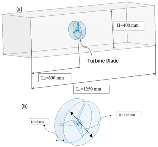
Figure 1.
Numerical model details: (a) dimensions of the structure and (b) dimensions of the blade zone.
The SST k-ω first-order turbulence approach is used in our numerical model. The Shear-Stress Transport SST k-ω turbulence model, developed by Menter (1994) [37], is an advanced tool in computational fluid dynamics (CFD) that can accurately predict turbulent flows by effectively modeling boundary layer effects near wind blades.
Figure 2 illustrates a flow chart outlining the diverse steps for elaborating the experimental and numerical studies. In fact, the flow chart outlines a methodology integrating both experimental and numerical approaches to optimize the performance of HAWTSav.
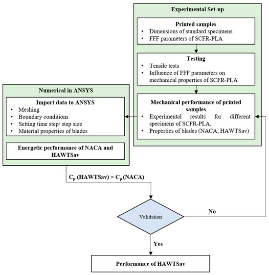
Figure 2.
Flow chart outlining the diverse steps for experimental and numerical studies.
The process begins with an experimental set-up, where printed samples are initially fabricated. This involves defining the dimensions of standard specimens and establishing parameters for FFF along with the selection of appropriate SCFR-PLA composites. Subsequently, tensile tests are conducted to evaluate the mechanical properties, focusing on the influence of FFF parameters on the performance of SCFR-PLA composites. Our study explores the latest advancements in polymer matrix composites, revealing improved performances that make these materials increasingly suitable for wind applications. Specifically, we aim to optimize FFF parameters to enhance the mechanical properties of SCFR-PLA. The developed experimental set-up is utilized in printing blades for HAWT with NACA profile and HAWTSav, respectively. Tensile tests were performed on standard specimens following ASTM 638-02a, utilizing different FFF parameters. Conventional stress–strain curves were obtained.
In previous studies, several key parameters affecting mechanical properties have been identified, including the percentage of carbon for printed composites, layer thickness, printing speed, and raster angle [32,38]. Specifically for SCFR-PLA, the raster angle is investigated at three levels: 0°, 45°, and 90°. Infill density is maintained at 80% to optimize mechanical properties, despite its impact on fabrication time and cost. Variation in layer thickness, set at 0.3 mm, directly influences the number of fused filament layers and subsequently alters mechanical properties. Additionally, the percentage of carbon is explored at three levels: 0%, 15%, and 30%. Three printing speeds, 30 mm/s, 50 mm/s, and 70 mm/s, are employed to examine their effects on the final printed parts. These parameters are critical for understanding and enhancing the mechanical performance of SCFR-PLA composites in FFF technology. Following the experimental phase, the flow chart highlights the identification of the best mechanical performance among the printed samples of SCFR-PLA, based on experimental results across different specimens. The flow chart then transitions to the numerical phase using ANSYS software 16.2. Here, the material properties obtained from the experimental tests are integrated into ANSYS for simulations. The process involves importing experimental data, performing meshing to create the computational domain, setting boundary conditions, and determining the appropriate time step or step size for accurate numerical analysis.
In the subsequent step, the numerical simulations focus on assessing the energetic performance of the NACA and HAWTSav blades. This involves analyzing factors such as power generation efficiency and structural integrity under varying wind conditions.
The final stage of the flow chart involves validation against established benchmarks. Specifically, if the power coefficient (Cp) of the HAWTSav exceeds that of a standard NACA profile, it validates the design’s efficacy and leads to a determination of overall performance enhancements for the HAWTSav.
3. Validation of Numerical Model: Blades with NACA Profile
The main goal of this section is to validate the proposed numerical model through a comparison of the results with those of previous work by Balasem et al. (2019) [10]. The numerical study was carried out on the same blade profile developed by Balasem et al. (2019) [10]. The meshed domain includes 2,618,291 elements and 461,829 nodes. A fine mesh was utilized specifically for the wind blades and the regions near them. The characteristics of wind turbine blades with NACA profile are presented in Table 1.

Table 1.
Technical characteristics of the wind turbine.
The mechanical properties of the printed ABS are summarized in Table 2.

Table 2.
Mechanical properties of ABS polymer [39].
This study presents results from simulations and experimental data, detailing the performance of the SST k-ω model at a velocity of V = 8 m/s. The figure shows good agreement between our numerical results and the experimental ones. In fact, the performance results were compared with those of the previous experimental study [10]. According to the simulation results, for the HAWT with NACA profile, obtained in this study, the maximum overall relative error was less than 5%, as shown in Figure 3. This indicates that the numerical method employed in this investigation accurately predicted the outcomes.
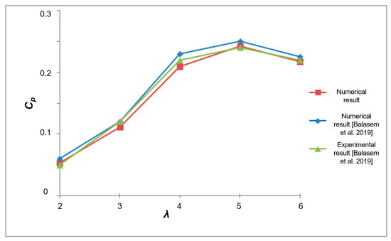
Figure 3.
Validation of the numerical model [10].
This model will be used to demonstrate the performance of HAWTSav with a Savonius profile. Its blades are printed using short carbon fiber-reinforced PLA composites (SCFR-PLA) by the FFF technology. PLA is a thermoplastic polymer, which is used in the 3D-printing process due to its ease of use and print. It is derived from renewable resources, offering biodegradability properties.
4. Influence of FFF Parameters on Mechanical Properties of SCFR-PLA Composites
The standard specimen is used for tensile testing. Tensile tests are conducted at room temperature (25 °C). The test was performed at a crosshead speed of 5 mm/min. An extensometer was used to accurately measure the elongation of the specimen during tensile testing, ensuring precise strain characterization. The specimens are fabricated using the FFF technique, commonly known as 3D printing. This technique ensures precise fabrication of the specimens to meet the dimensional and material requirements specified by the ASTM standard. Indeed, an experimental study is conducted to characterize the mechanical behavior of the printed SCFR-PLA parts. PLA is a versatile matrix material for FFF, offering a balance of biodegradability, mechanical stability, and ease of processing. Its properties can be significantly enhanced by incorporating carbon fibers. The printability of the PLA can be optimized by adjusting FFF parameters. Optimizing printing parameters is crucial for enhancing the mechanical properties of PLA composites. For that, diverse tests were elaborated to investigate the effects of carbon content, printing speed, and raster angle on the elastic properties of the SCFR-PLA composite. The FFF tests are elaborated with a layer thickness of 0.3 mm. The composite filament used has a diameter of 1.75 mm. For the 3D-printed specimens, the extrusion temperature is set to 210 °C, while the bed temperature is maintained at 60 °C to ensure proper adhesion and layer bonding during the printing process. Uniaxial tensile tests are conducted on all SCFR-PLA samples, employing various printing orientations, different carbon fiber proportions, and different printing speeds, until failure occurs. We illustrate in Figure 4 some experimental results obtained by tensile tests.
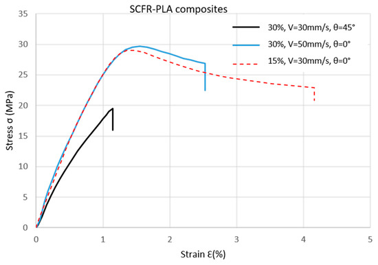
Figure 4.
Tensile curves of printed SCFR-PLA with different FDM parameters.
In our study, we employ a full factorial experimental design with 27 tests (3 levels for carbon percentage, 3 levels for printing speed, and 3 levels for raster angle). Each tensile test is conducted twice for every set of printing parameters to minimize the contrast of the measurements, and the average values are used to plot the stress–strain curve. The mean of a mechanical property (e.g., elastic modulus E, yield strength YS, or ultimate tensile strength UTS) in an experiment is calculated as the sum of all individual measured responses for that property, divided by the total number of measurements. Its value, for each property, is calculated using Equation (1):
where Y is the mean mechanical property value, X represents the individual response values for the mechanical property from the experiment, and N is the total number of experimental measurements at a specific parameter level. This formula (Equation (1)) is used to calculate the average of a mechanical property for a single experimental condition, such as a specific FFF parameter at a particular level. We present in the following figures the impact of these input factors on the mechanical properties of SCFR-PLA composites.
As shown in Figure 5, the carbon percentage plays a critical role in determining mechanical properties. A carbon content of 15% offers a balanced enhancement in performance, as it increases stiffness (Figure 5a) and strength while maintaining sufficient ductility. Higher carbon percentages, such as 30%, result in improved strength (Figure 5b,c) but introduce significant brittleness, making the material unsuitable for applications requiring durability and flexibility. Hence, 15% carbon is optimal, offering improved mechanical properties without compromising the overall integrity of the structure. Therefore, based on the conducted tests and analysis, we recommend the selection of SCFR-PLA with a carbon content of 15% for the manufacturing of wind blades with a Savonius profile (HAWTSav).
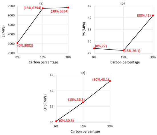
Figure 5.
Influence of carbon percentage on mechanical properties: (a) Elastic modulus, (b) Yield strength, (c) Ultimate tensile strength.
As shown in Figure 6, we recommend 50 mm/s, as it provides the ideal compromise between mechanical performance and production efficiency. Printing speed significantly affects elastic properties, with higher speeds (e.g., 70 mm/s) leading to a reduction in rigidity (Figure 6a) and offering no significant benefits in terms of YS and UTS (Figure 6b,c). Conversely, lower speeds (e.g., 30 mm/s) result in lengthy operation times and increased costs without a proportional improvement in mechanical properties. Thus, a speed of 50 mm/s ensures efficient production while maintaining desirable levels of stiffness and strength.
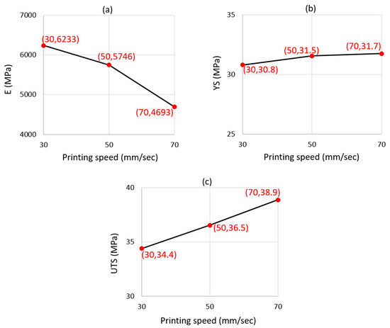
Figure 6.
Influence of printing speed on mechanical properties: (a) Elastic modulus, (b) Yield strength, (c) Ultimate tensile strength.
Based on Figure 7, increasing the raster angle from 0° to 90° significantly reduced stiffness in SCFR-PLA samples. Carbon percentage strongly affects mechanical properties, enhancing performance as it increases. However, achieving the optimal carbon balance is crucial, as higher percentages can increase brittleness. Printing speed moderately influences elastic properties (Figure 7a), but its impact is overshadowed by carbon percentage and raster angle.
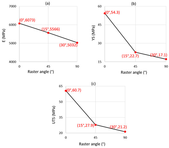
Figure 7.
Influence of raster angle on mechanical properties: (a) Elastic modulus, (b) Yield strength, (c) Ultimate tensile strength.
Finally, a raster angle of 0° is selected, as it yields superior mechanical properties compared to other orientations. The alignment of the fibers in the direction of load application enhances stiffness (Figure 7a), strength (Figure 7b,c), and overall structural integrity. This combination of SCFR-PLA with 15% carbon, a printing speed of 50 mm/s, and a raster angle of 0° provides an optimal solution for manufacturing robust and efficient wind blades with the Savonius profile, ensuring high performance and cost-effectiveness.
5. Comparison Between Blades with NACA and Savonius Profiles
FFF printing technology is employed for producing parts from SCFR-PLA. ABS is typically printed at higher temperatures around 250 °C, whereas SCFR-PLA is printed at lower temperatures, approximately 210 °C, which facilitates easier printing compared to ABS. SCFR-PLA combines the biodegradability and printability advantages of PLA with enhanced stiffness and strength from carbon fiber reinforcement, offering improved mechanical properties. Then, the SCFR-PLA composite is suitable for applications demanding a balance of strength, stiffness, and ease of printing, such as those requiring a Savonius profile for HAWT applications.
For the numerical level, Figure 8 provides detailed views of the mesh configuration applied to the HAWTSav with the Savonius blade profile.
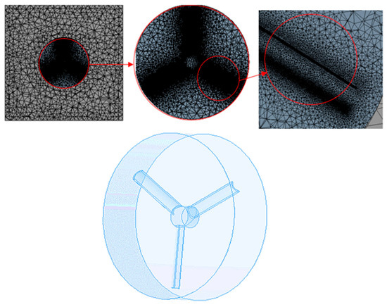
Figure 8.
Computational meshing of HAWTSav.
The characteristics of HAWTSav with the Savonius profile are presented in Table 3.

Table 3.
Technical characteristics of the wind turbine HAWTSav.
The accuracy of the developed model was proved through comparisons of computed results with experimental data provided by Balasem et al. (2019) [10]. Figure 9 illustrates the numerical results of the mechanical strength analysis of printed blades featuring NACA and HAWTSav blade profiles, fabricated using ABS and SCFR-PLA materials, respectively. The study focuses on evaluating the distribution of strain and stress within the blades to identify critical regions and determine the maximum values of displacement, strain, and stress under specific loading conditions. The numerical simulations provide insight into the structural performance of the blades, highlighting material-dependent differences in mechanical behavior and the impact of blade geometry on stress distribution (Figure 9).
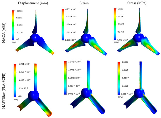
Figure 9.
Technical characteristics of the wind turbine HAWTSav.
The results indicate that the HAWTSav blade profile, fabricated using SCFR-PLA composite, demonstrates superior mechanical performance compared to the NACA blade profile made from ABS polymer. Although the maximum stress for the NACA blade is higher at 1.105 MPa compared to 0.6033 MPa for HAWTSav, the strain values tell a different story. The maximum strain for HAWTSav is significantly lower (1.341 × 10⁻4) than that of NACA (4.251 × 10⁻4), indicating that the HAWTSav blade experiences less deformation under load. This enhanced stiffness and reduced strain can be attributed to the optimized FFF parameters used for SCFR-PLA fabrication, including a 15% carbon fiber content, a printing speed of 50 mm/s, and a raster angle of 0°. These settings significantly improve the material’s strength and the overall durability of the blade in the HAWTSav profile, making it mechanically more robust than the ABS-fabricated NACA blade.
Now, from an energy efficiency standpoint, Figure 10 illustrates the computed coefficient of power (Cₚ) across various tip speed ratios (λ) for the NACA and HAWTSav blade profiles, manufactured using ABS polymer and 3D-printed SCFR-PLA composite, respectively. The results indicate that the HAWTSav blade design increases power extraction. These combined factors make the HAWTSav blade a promising choice, which leads to higher energy conversion and improved turbine performance.
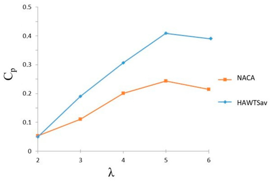
Figure 10.
CP for NACA and HAWTSav blades.
Multiple ANSYS FLUENT simulation scenarios will be developed for the HAWT with a NACA profile and the HAWTSav featuring a Savonius profile. These scenarios evaluated performance across different tip speed ratios. Numerical simulations were conducted using the commercial computational fluid dynamics (CFD) software ANSYS FLUENT 6.12. The simulations considered an inlet velocity of 8 m/s, representing the nominal wind speed. Within the rotating domain, the fluid’s angular velocity was specified. The pressure field was determined using a SIMPLE (Semi-Implicit Method for Pressure-Linked Equations) algorithm, which couples pressure and velocity fields to solve for the flow characteristics accurately. Figure 11 shows the distribution of pressure for a different tip speed ratio λ (2, 4, 6).
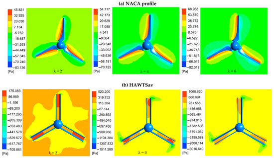
Figure 11.
Pressure distribution (z = 0.012 m): (a) HAWT with NACA profile and (b) HAWTSav.
It can be seen for the two configurations studied that the pressure values are increasing as a function of the increase in the tip speed ratio values. For the pressure, it is noted that the maximum values are more important for the new configuration. This result is due to the concave form of the blades of the HAWTSav.
Figure 12 shows the turbulent kinetic energy for a different tip speed ratio λ (2, 4, 6) and compares the kinetic energy aspects between HAWT with NACA and Savonius profiles. These cases compare the performance of these blade configurations, showing how effectively they convert wind energy into kinetic energy.
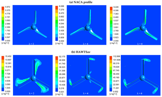
Figure 12.
Kinetic energy: (a) HAWT with NACA profile and (b) HAWTSav.
For the two configurations, the turbulent kinetic energy increases as a function of the increase in the tip speed ratio values. We noticed that the values are very low upstream of the NACA wind turbine and a small increase in these values is observed at the tips of the blades. For the HAWTSav, upstream, the values are recorded as negligible except in the region surrounding the rotating domain. Moving to the blade tips, an improvement in the turbulent kinetic energy values is noted. Focusing on the turbulent kinetic energy values, it is observed that the λ = 6 configuration generates the highest energy for both wind turbine configurations (NACA and HAWTSav) with higher values in the case of the HAWTSav.
6. Conclusions
This study demonstrates the transformative potential of 3D printing in advancing wind energy systems, particularly through the fabrication of lightweight, efficient, and customizable turbine components. The adoption of fused filament fabrication (FFF) technology with short carbon fiber-reinforced PLA (SCFR-PLA) composites has enabled the production of innovative blade designs, such as the HAWTSav configuration, which exhibit improved energy efficiency and mechanical robustness. For the Savonius-profile blade made of SCFR-PLA with 15% carbon, a printing speed of 50 mm/s and a raster angle of 0° provide the best mechanical performance. The strain for the Savonius profile blade made of SCFR-PLA was significantly lower than that of the NACA profile blade made of ABS, showing an improvement of 68.5%. In addition, the numerical model employed in this study successfully reproduced and quantified the effects of different configurations, providing detailed flow analyses and performance metrics. The comparative evaluation revealed that the new HAWTSav blade design, manufactured using optimized FFF parameters with SCFR-PLA composite, delivered superior energy results compared to conventional designs.
Additionally, for the NACA profile, the kinetic energy distribution remains localized near the blades with relatively lower values. As λ increases, the kinetic energy rises slightly but stays concentrated near the blade surfaces. In contrast, the HAWTSav configuration exhibits significantly higher kinetic energy values with strong wake structures, especially at λ = 2, suggesting increased energy dissipation. As λ increases, the kinetic energy around the blades increases. In addition, the HAWTSav configuration exhibits a significant improvement in kinetic energy compared to the HAWT with NACA profile across all tip speed ratios (λ). Specifically, for λ = 2, the maximum kinetic energy around turbine blades increases from 5.97 to 15.45 J/kg. This trend highlights the superior efficiency of the HAWTSav design, particularly at higher λ values.
Finally, this research provides a robust approach to optimizing the mechanical and energetic performance of 3D-printed wind turbine blades. While promising, further research is needed to scale up the manufacturing process, particularly by exploring the feasibility, efficiency, and durability of medium-sized blades in multi-stage configurations for larger HAWTs with different profiles.
Author Contributions
Conceptualization: L.B.S. and S.K.; methodology: W.Z. and A.C.; validation: B.A.; data curation: M.A.; writing—original draft preparation: H.H. All authors have read and agreed to the published version of the manuscript.
Funding
This research has been funded by Scientific Research Deanship at University of Ha’il–Saudi Arabia through project number RG-24 002.
Data Availability Statement
The original contributions presented in this study are included in the article. Further inquiries can be directed to the corresponding author.
Conflicts of Interest
The authors declare no conflicts of interest.
References
- Lemartinel, A.; Castro, M.; Fouché, O.; De-Luca, J.-C.; Feller, J.-F. A Review of Nanocarbon-Based Solutions for the Structural Health Monitoring of Composite Parts Used in Renewable Energies. J. Compos. Sci. 2022, 6, 32. [Google Scholar] [CrossRef]
- Firoozi, A.A.; Firoozi, A.A.; Hejazi, F. Innovations in Wind Turbine Blade Engineering: Exploring Materials, Sustainability, and Market Dynamics. Sustainability 2024, 16, 8564. [Google Scholar] [CrossRef]
- Rouway, M.; Nachtane, M.; Tarfaoui, M.; Chakhchaoui, N.; Omari, L.E.H.; Fraija, F.; Cherkaoui, O. Mechanical Properties of a Biocomposite Based on Carbon Nanotube and Graphene Nanoplatelet Reinforced Polymers: Analytical and Numerical Study. J. Compos. Sci. 2021, 5, 234. [Google Scholar] [CrossRef]
- Ebrahimpour, M.; Shafaghat, R.; Alamian, R.; Safdari Shadloo, M. Numerical Investigation of the Savonius Vertical Axis Wind Turbine and Evaluation of the Effect of the Overlap Parameter in Both Horizontal and Vertical Directions on Its Performance. Symmetry 2019, 11, 821. [Google Scholar] [CrossRef]
- Im, H.; Kim, B. Power Performance Analysis Based on Savonius Wind Turbine Blade Design and Layout Optimization through Rotor Wake Flow Analysis. Energies 2022, 15, 9500. [Google Scholar] [CrossRef]
- Chitura, A.G.; Mukumba, P.; Lethole, N. Enhancing the Performance of Savonius Wind Turbines: A Review of Advances Using Multiple Parameters. Energies 2024, 17, 3708. [Google Scholar] [CrossRef]
- Roy, S.; Saha, U.K. Review on the numerical investigations into the design and development of Savonius wind rotors. Renew. Sustain. Energy Rev. 2013, 24, 73–83. [Google Scholar] [CrossRef]
- Rahman, M.; Maroha, E.; El Shahat, A.; Soloiu, V.; Ilie, M. Aerodynamic Performance and Vibration Analyses of Small Scale Horizontal Axis Wind Turbine with Various Number of Blades. J. Power Energy Eng. 2018, 6, 76–105. [Google Scholar] [CrossRef][Green Version]
- Zhao, T.; Zhang, X.; Zheng, M. Blade number effect on the optimal energy efficiency for a modified Savonius rotor. Proceedings of the Institution of Civil Engineers. Energy 2020, 173, 101–108. [Google Scholar]
- Balasem, A.; Al-Quraishi, J.; Asmuin, N.; Nemah, M.N.; Salih, A. Experimental and Simulation Investigation for Performance of A Small-Scale Model of Bare and Shrouded HAWT. Int. J. Mech. Eng. Technol. 2019, 10, 434–449. [Google Scholar]
- Al-Gburi, K.A.H.; Al-quraishi, B.A.J.; Ismail Alnaimi, F.B.; Tan, E.S.; Al-Safi, A.H. Experimental and Simulation Investigation of Performance of Scaled Model for a Rotor of a Savonius Wind Turbine. Energies 2022, 15, 8808. [Google Scholar] [CrossRef]
- Sivamani, S.; Premkumar, M.T.; Kumar, V.D.; Reddy, V.K.K.; Reddy, K.D.; Reddy, K.D.; Hariram, V. Experimental data on analysis of a horizontal axis small wind turbine with blade tip power system using permanent magnetic generator. Data Brief 2019, 23, 103716. [Google Scholar] [CrossRef] [PubMed]
- Huang, Y.; Kormakov, S.; He, X.; Gao, X.; Zheng, X.; Liu, Y.; Sun, J.; Wu, D. Conductive Polymer Composites from Renewable Resources: An Overview of Preparation, Properties, and Applications. Polymers 2019, 11, 187. [Google Scholar] [CrossRef] [PubMed]
- Teng, H.; Li, S.; Cao, Z.; Li, S.; Li, C.; Ko, T.J. Carbon Fiber Composites for Large-Scale Wind Turbine Blades: Applicability Study and Comprehensive Evaluation in China. J. Mar. Sci. Eng. 2023, 11, 624. [Google Scholar] [CrossRef]
- Reddy, S.S.P.; Suresh, R.; MB, H.; Shivakumar, B.P. Use of composite materials and hybrid composites in wind turbine blades. Mater. Today Proc. 2021, 46, 2827–2830. [Google Scholar] [CrossRef]
- Elhenawy, Y.; Fouad, Y.; Marouani, H.; Bassyouni, M. Simulation of Glass Fiber Reinforced Polypropylene Nanocomposites for Small Wind Turbine Blades. Processes 2021, 9, 622. [Google Scholar] [CrossRef]
- Ammar, S.; Ben Fraj, B.; Hentati, H.; Saouab, A.; Ben Amar, M.; Haddar, M. Mechanical performances of printed carbon fiber-reinforced PLA and PETG composites. Proc. Inst. Mech. Eng. Part L J. Mater. Des. Appl. 2024, 238, 1488–1499. [Google Scholar] [CrossRef]
- Han, X.; Hua, L. Comparison between cold rotary forging and conventional forging. J. Mech. Sci. Technol. 2009, 23, 2668. [Google Scholar] [CrossRef]
- Hammami, C.; Kammoun, N.; Hentati, H.; Amar, M.B.; Haddar, M. Parametric analysis of the damage characterization tests of aluminum bulk material. J. Mech. Sci. Technol. 2022, 36, 5019–5025. [Google Scholar] [CrossRef]
- Ben Fraj, B.; Kamoun, T.; Hentati, H.; Trabelsi, M.; Ghazouani, N.; Ahmed, M. Optimization of forming force and Erichsen index using Taguchi design of experiments: Mathematical models and experimental validation. Proc. Inst. Mech. Eng. Part B J. Eng. Manuf. 2023, 238, 1316–1326. [Google Scholar] [CrossRef]
- Ben Said, L.; Wali, M. Accuracy of Variational Formulation to Model the Thermomechanical Problem and to Predict Failure in Metallic Materials. Mathematics 2022, 10, 3555. [Google Scholar] [CrossRef]
- Ali, S.; Mehra, V.; Eltaggaz, A.; Deiab, I.; Pervaiz, S. Optimization and prediction of additively manufactured PLA-PHA biodegradable polymer blend using TOPSIS and GA-ANN. Manuf. Lett. 2024, 41, 795–802. [Google Scholar] [CrossRef]
- Aljafari, B.; Samithas, D.; Balachandran, P.K.; Anandan, S.; Babu, T.S. Performance Analysis of PLA Material Based Micro-Turbines for Low Wind Speed Applications. Polymers 2022, 14, 4180. [Google Scholar] [CrossRef] [PubMed]
- Suresh A, Raja kumar S, Belqasem Aljafari, Sudhakar Babu Thanikanti, Investigations of the performance of 3D printed micro wind turbine composed of PLA material. Heliyon 2024, 10, e25356. [CrossRef] [PubMed]
- Zarzoor, A.; Jaber, A.; Shandookh, A. 3D Printing for wind turbine blade manufacturing: A review of materials, design optimization, and challenges. Eng. Technol. J. 2024, 42, 895–911. [Google Scholar] [CrossRef]
- Ramírez-Elías, V.A.; Damian-Escoto, N.; Choo, K.; Gómez-Martínez, M.A.; Balvantín-García, A.; Diosdado-De la Peña, J.A. Structural Analysis of Carbon Fiber 3D-Printed Ribs for Small Wind Turbine Blades. Polymers 2022, 14, 4925. [Google Scholar] [CrossRef]
- Benmoussa, A.; Pascoa, J.C. Enhancement of a cycloidal self-pitch vertical axis wind turbine performance through DBD plasma actuators at low tip speed ratio. Int. J. Thermofluids. 2022, 17, 100258. [Google Scholar] [CrossRef]
- Zargar, O.A.; Lin, T.; Gare Zebua, A.; Lai, T.J.; Shih, Y.C.; Hu, S.C.; Leggett, G. The effects of surface modification on aerodynamic characteristics of airfoil DU 06 W 200 at low Reynolds numbers. Int. J. Thermofluids 2022, 16, 100208. [Google Scholar] [CrossRef]
- Sinha, A.; Swain, B.; Behera, A.; Mallick, P.; Samal, S.K.; Vishwanatha, H.M.; Behera, A. A Review on the Processing of Aero-Turbine Blade Using 3D Print Techniques. J. Manuf. Mater. Process. 2022, 6, 16. [Google Scholar] [CrossRef]
- Lipian, M.; Kulak, M.; Stepien, M. Fast track integration of computational methods with experiments in small wind turbine development. Energies 2019, 12, 1625. [Google Scholar] [CrossRef]
- Corvi, A.; Collini, L.; Sciancalepore, C.; Kumar, A. Analysis and modelling of damage mechanism in FDM 3D-printed lattice structure under compression loading. J. Mech. Eng. Sci. Technol. 2023, 37, 1089–1095. [Google Scholar] [CrossRef]
- Allouch, M.; Ben Fraj, B.; Dhouioui, M.; Kesssentini, A.; Hentati, H.; Wali, W.; Ferhi, M. Mechanical, microstructural and numerical investigations of 3D printed carbon fiber reinforced PEEK. Proc. Inst. Mech. Eng. Part C J. Mech. Eng. Sci. 2024, 238, 2131–2139. [Google Scholar] [CrossRef]
- Al Zahmi, S.; Alhammadi, S.; ElHassan, A.; Ahmed, W. Carbon Fiber/PLA Recycled Composite. Polymers 2022, 14, 2194. [Google Scholar] [CrossRef] [PubMed]
- Gvali, V.; Kubade, P.; Kulkarni, H. Mechanical and Thermo-mechanical Properties of Carbon fiber Reinforced Thermoplastic Composite Fabricated Using Fused Deposition Modeling Method. Mater. Today Proc. 2020, 22, 1786–1795. [Google Scholar] [CrossRef]
- Kessler, E.; Gadow, R.; Straub, J. Basalt, glass and carbon fibers and their fiber reinforced polymer composites under thermal and mechanical load. AIMS Mater. Sci. 2016, 3, 1561–1576. [Google Scholar] [CrossRef]
- Kamaal, M.; Anas, M.; Rastogi, H.; Bhardwaj, N.; Rahaman, A. Effect of FDM process parameters on mechanical properties of 3D-printed carbon fibre–PLA composite. Prog. Addit. Manuf. 2020, 6, 63–69. [Google Scholar] [CrossRef]
- Menter, F.R. Two-Equation Eddy-Viscosity Turbulence Models for Engineering Applications. AIAA J. 1994, 32, 1598–1605. [Google Scholar] [CrossRef]
- Rodríguez-Panes, A.; Claver, J.; Camacho, A.M. The Influence of Manufacturing Parameters on the Mechanical Behaviour of PLA and ABS Pieces Manufactured by FDM: A Comparative Analysis. Materials 2018, 11, 1333. [Google Scholar] [CrossRef]
- Golubović, Z.; Danilov, I.; Bojović, B.; Petrov, L.; Sedmak, A.; Mišković, Ž.; Mitrović, N. A Comprehensive Mechanical Examination of ABS and ABS-like Polymers Additively Manufactured by Material Extrusion and Vat Photopolymerization Processes. Polymers 2023, 15, 4197. [Google Scholar] [CrossRef]
Disclaimer/Publisher’s Note: The statements, opinions and data contained in all publications are solely those of the individual author(s) and contributor(s) and not of MDPI and/or the editor(s). MDPI and/or the editor(s) disclaim responsibility for any injury to people or property resulting from any ideas, methods, instructions or products referred to in the content. |
© 2025 by the authors. Licensee MDPI, Basel, Switzerland. This article is an open access article distributed under the terms and conditions of the Creative Commons Attribution (CC BY) license (https://creativecommons.org/licenses/by/4.0/).