1. Introduction
Steel bridges, characterized by long spans, high load-bearing efficiency, and short construction periods, are widely employed in highway, railway, and urban transportation infrastructure. However, during long-term service, factors such as environmental exposure, increased loads, and functional changes often induce cracking and damage in existing steel structures, necessitating strengthening to ensure operational safety and durability [
1]. Consequently, the development of efficient and reliable strengthening techniques for damaged steel bridges has become a critical research focus in the field of civil engineering [
2].
Carbon fiber-reinforced polymer (CFRP) has been widely employed for steel structure strengthening due to its high strength-to-weight ratio, corrosion resistance, and excellent fatigue performance [
3]. Compared with welding or bolted strengthening, CFRP avoids issues such as heat-affected zone embrittlement or stress concentration around bolt holes, thereby preventing secondary damage to the original structure [
4]. However, the effectiveness of CFRP strengthening largely depends on the bonding performance at the CFRP–steel interface [
5], and interfacial failure often limits the utilization of CFRP strength to less than 50% for the purely bonding method, hindering its high-strength potential [
6].
To improve interfacial performance, physical treatments such as sandblasting and mechanical grinding have been proposed, with sandblasting being widely adopted due to its ease of application and moderate cost [
7,
8]. Increased surface roughness enhances the “mechanical interlock” effect, significantly improving interfacial resistance to debonding [
9]. However, most existing studies focus on the short-term effects of different roughness levels on interfacial performance, while research on the influence of surface roughness on the long-term performance of strengthened beams in service environments remains insufficient. Under high-temperature and high-humidity conditions, the adhesive is prone to aging, leading to interfacial degradation and premature failure [
10], but the differences in the ability of bonding interfaces with distinct bonding mechanisms (e.g., “pure bonding” or “mechanical interlocking + bonding”) to resist hygrothermal deterioration and maintain long-term stability remain unclear.
In addition, the development of prestressed CFRP technology offers another means to enhance strengthening effectiveness [
11]. By applying a pre-tension force, CFRP can partially counteract stresses induced by external loads, reducing the stress intensity factor at crack tips and suppressing crack propagation rates [
12,
13]. Simultaneously, it optimizes the synergistic behavior between CFRP and steel, significantly improving the utilization efficiency of CFRP materials. It also alleviates the concentration of interfacial shear stress, thereby delaying interfacial debonding [
14]. Extensive research and engineering applications have demonstrated that prestressed CFRP strengthening can substantially improve both the static and fatigue performance of steel beams [
15,
16,
17].
Despite the significant advantages of prestressed CFRP technology in steel bridge strengthening, several key issues need to be clarified when applying this technology to engineering practice. Specifically, the comprehensive influence of laws of critical processes and parameters—such as steel surface treatment, CFRP prestress level, end anchorage, and service environment—on the strengthened system has not been fully addressed in existing studies. Although it is known that hygrothermal environments can accelerate adhesive aging and interfacial degradation, thereby impairing the mechanical performance of the strengthened structure [
18,
19,
20], the long-term stability of interfaces with different steel surface roughness levels and their effects on the strengthening effectiveness of prestressed CFRP remain unclear. Therefore, it is essential to investigate the impacts of these parameters on the strengthened system to optimize the flexural performance and environmental adaptability of the system.
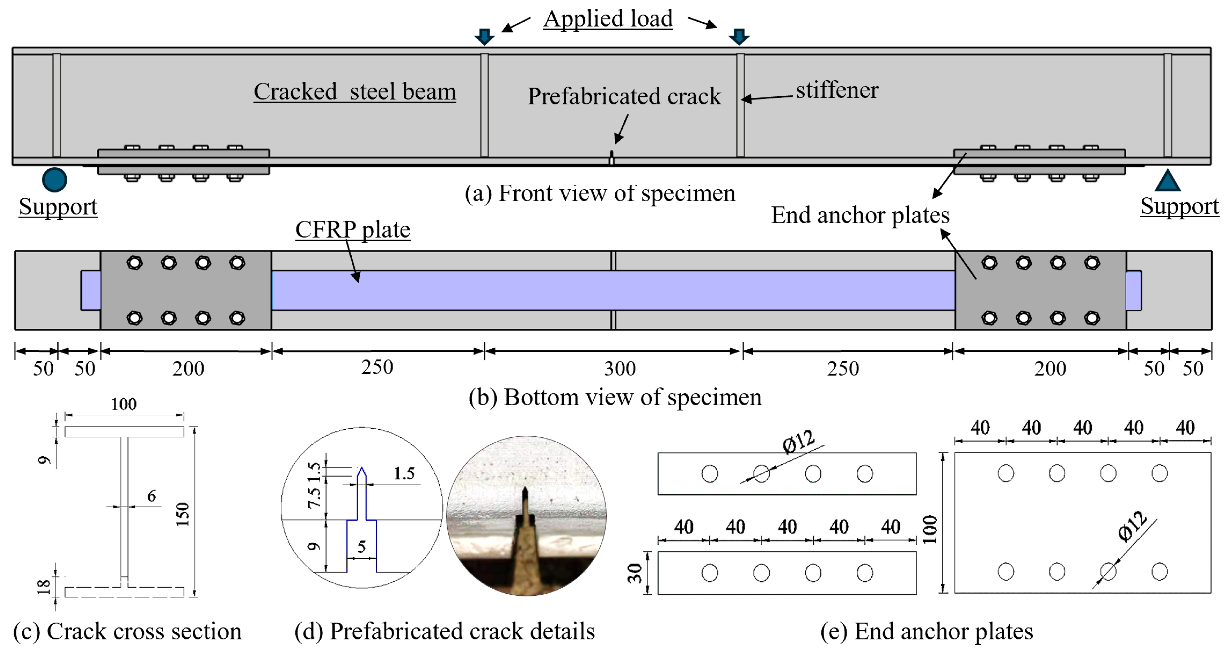
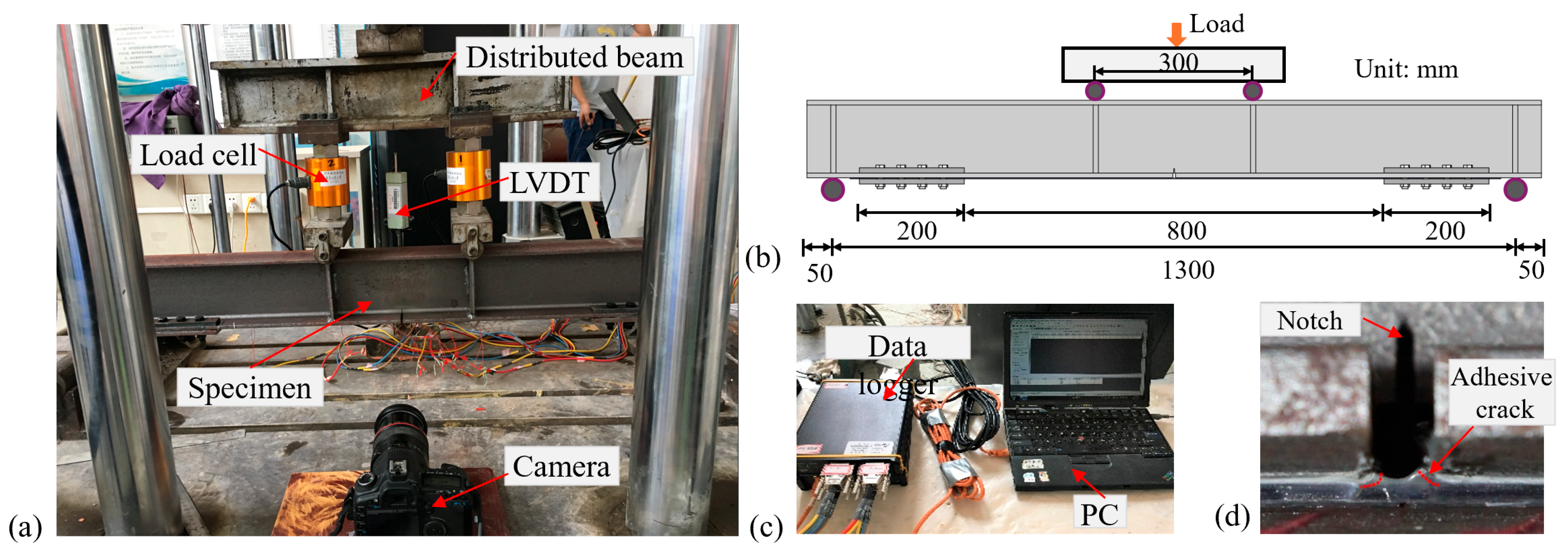
Against this background, this study focuses on the flexural performance of cracked steel beams strengthened with CFRP and considers four factors: steel surface roughness, end anchor, CFRP prestress, and hygrothermal durations. Nine pre-cracked steel beam specimens were designed, and four-point bending tests were conducted to explore the influence of each parameter on the flexural performance of the strengthened system, providing a scientific basis and practical guidance for the design of CFRP strengthening for damaged steel bridges in hygrothermal regions.
3. Experimental Results and Discussion
3.1. Load–Deflection Response
The load-deflection response of all specimens is presented in
Figure 6. The load–deflection curve of the reference beam (B0) exhibited the typical “elastic–plastic–brittle failure” behavior, which reflects the evolution of the initial web cracks. In the elastic stage, the internal stresses did not exceed the steel yield limit, and the load–deflection relationship remained approximately linear. Once the load surpassed the elastic threshold, stress concentration at the crack tip induced plastic deformation, causing a marked increase in deflection rate. Ultimately, at the ultimate load, the crack rapidly propagated through the section, significantly reducing the effective cross-sectional area and leading to sudden brittle failure. This behavior serves as a baseline for evaluating the performance of strengthened specimens.
Non-prestressed CFRP-strengthened specimens effectively extended the elastic stage and significantly enhanced stiffness through the synergistic action between the CFRP plate and the steel beam. The key mechanism lies in the CFRP sharing tensile stresses and inhibiting early crack plasticization. The presence of end anchors constrained the slip at the CFRP plate ends, promoting a more uniform interfacial shear stress distribution, thereby delaying adhesive layer cracking and maintaining residual load-carrying capacity after partial CFRP debonding. In contrast, specimens without anchors exhibited load–deflection behavior that rapidly approached that of B0 after debonding. Sandblasting grade also substantially influenced the interfacial bonding mechanism: Sa3 sandblasting formed a “mechanical interlock + adhesion” composite interface, providing superior shear resistance compared with the adhesion-only Sa2 interface. Consequently, Sa3 specimens (B2, B2P0) showed delayed adhesive cracking and debonding. However, due to errors in the experimental arrangement for specimen fabrication and loading, specimen B2 did not receive sufficient curing time for the adhesive layer. Consequently, it exhibited a lower peak load compared to specimen B1. This also indirectly indicates that in the practical application of engineering reinforcement, sufficient curing of the interface requires focused attention.
Prestressed specimens (B1P2, B2P2) demonstrated a more stable linear elastic stage because the CFRP plates were already in tension at the early loading stage, enhancing the synergistic action with the steel beam and slowing the load drop after debonding, thereby improving structural ductility relative to non-prestressed specimens. Hygrothermal cycling (B1P2H, B2P2H) accelerated adhesive aging and interfacial degradation, shortening the elastic stage, advancing debonding, and promoting brittle failure modes (e.g., CFRP rupture at ultimate load in B2P2H). Notably, Sa3 sandblasting partially mitigated the detrimental effects of the hygrothermal environment. The “mechanical interlock” interface exhibited enhanced resistance to degradation, resulting in higher first debonding load and ultimate load for B2P2H compared with B1P2H with Sa2 treatment. This indicates that high-roughness surface treatment can delay the degradation of CFRP-strengthened systems under hygrothermal service conditions.
3.2. Analysis of Flexural Performance Indicators
To compare the effectiveness of different strengthening schemes under various conditions, the loads corresponding to steel beam crack-tip yielding, adhesive layer cracking, web cracking, and ultimate failure are summarized in
Table 3. The load at crack-tip yielding was determined using strain gauges attached at the crack tips, while the loads for adhesive layer cracking and web cracking were identified from photographs taken during testing. The ultimate load is defined as the load at final failure of the specimen. Note that data for specimen B1P0 are not included in
Table 3 due to strain gauge malfunction during the test.
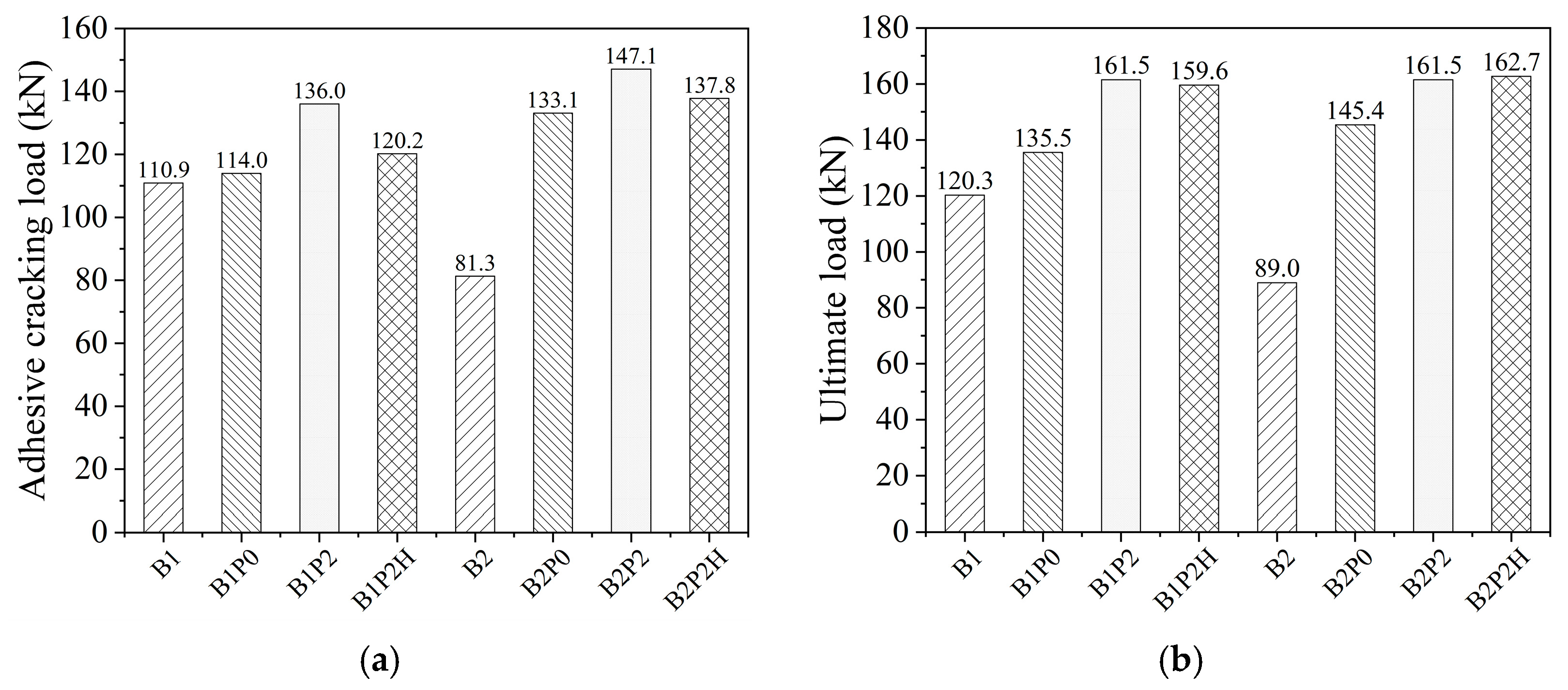
The adhesive cracking loads of different specimens are presented in
Figure 7a. As previously noted, specimen B2 exhibited a lower cracking load due to insufficient adhesive curing. Comparison between non-prestressed and prestressed specimens indicates that the application of prestress significantly increased the adhesive cracking load and effectively delayed adhesive failure. Under the Sa2 sandblasting grade, the prestressed specimen B1P2 showed a 19.3% increase in adhesive cracking load compared with the non-prestressed B1P0, whereas after 90 hygrothermal cycles, B1P2H decreased by 11.6% relative to B1P2. Under the Sa3 sandblasting grade, the prestressed specimen B2P2 exhibited a 10.5% increase over B2P0, and B2P2H decreased by 6.3% after 90 hygrothermal cycles. Moreover, the variation in cracking load for Sa3 specimens was smaller than that for Sa2 specimens. Further comparison between specimens with different surface roughness under the same conditions shows that B2P0 increased the cracking load by 19.1 kN relative to B1P0, B2P2 increased by 11.1 kN relative to B1P2, and B2P2H increased by 17.6 kN relative to B1P2H. These results indicate that higher surface roughness effectively enhances interfacial bond strength and the corresponding adhesive cracking load, and better mitigates the deterioration of the interface under hygrothermal conditions.
The ultimate loads of different specimens are shown in
Figure 7b. Under the Sa2 sandblasting grade, the specimen B1P0 with end anchors exhibited an ultimate load 12.2 kN higher than the unanchored specimen B1. This improvement is primarily attributed to the end anchors allowing the CFRP plate to continue carrying load after full-length debonding, thereby enhancing the safety reserve of the strengthened steel beam. Meanwhile, the prestressed specimen B1P2 showed an ultimate load increase of 26 kN compared with the non-prestressed B1P0, whereas the difference between B1P2H after 90 hygrothermal cycles and B1P2 was only 1.9 kN. Specimens under the Sa3 sandblasting grade exhibited similar trends (B2 was excluded due to insufficient adhesive curing). The prestressed B2P2 had an ultimate load 16.1 kN higher than the non-prestressed B2P0, with only a 1.2 kN reduction after 90 hygrothermal cycles (B2P2H). Overall, the hygrothermal environment has a significant effect on adhesive cracking load but a relatively minor effect on ultimate load. This indicates that hygrothermal aging primarily accelerates interfacial degradation; however, when end anchors are employed, its impact on the overall load-carrying capacity of the strengthened beams is limited.
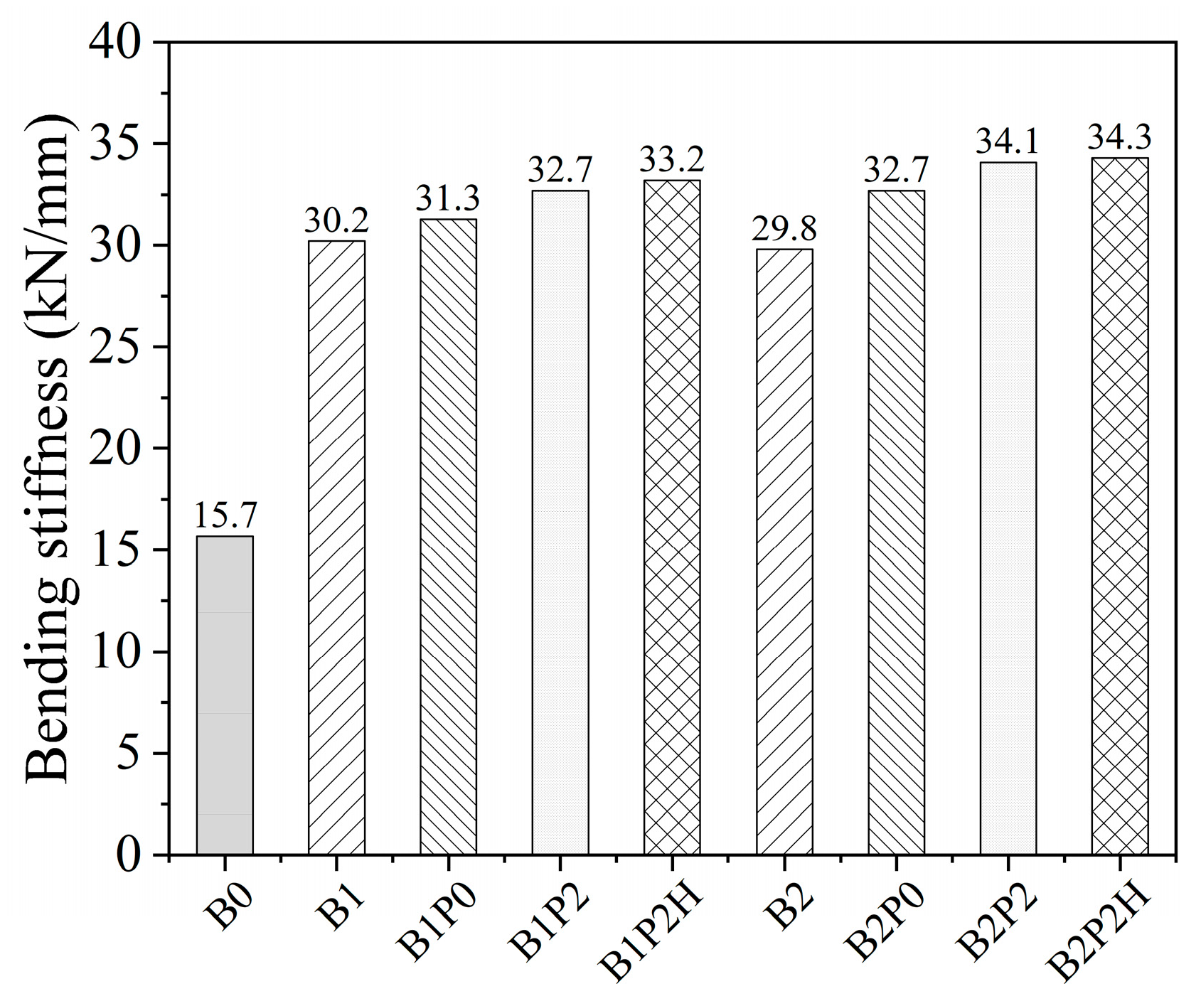
In this study, stiffness is defined as the slope of the load–midspan deflection curve prior to the occurrence of interfacial cracks in the steel beam, representing the load-carrying stiffness of the strengthened beam during the elastic stage. The relevant parameters are listed in
Table 3. The stiffness of all specimens is shown in
Figure 8. Compared with the reference specimen B0, all strengthened specimens exhibited a significant increase in elastic-stage stiffness. Non-prestressed specimens with different surface roughness showed similar stiffness improvements, approximately 91.1%, whereas prestressed specimens exhibited an overall increase of about 112.7%. Notably, the additional contribution of prestress to stiffness was not significant compared with non-prestressed specimens, consistent with previous studies [
27,
28], indicating that the stiffness of CFRP-strengthened beams primarily depends on the geometry and mechanical properties of the CFRP rather than the prestress level when the elastic modulus of CFRP is comparable to that of steel. Furthermore, comparison between prestressed specimens with and without hygrothermal treatment shows that 90 hygrothermal cycles had a limited effect on stiffness, suggesting that under the experimental conditions of this study, the hygrothermal environment has minimal influence on the elastic-stage performance of CFRP-strengthened steel beams.
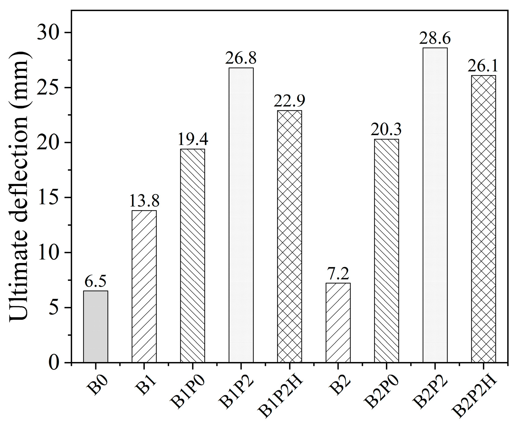
The ultimate deflections of the specimens are shown in
Figure 9. Compared with the reference specimen B0, the ultimate deflections of unanchored specimens B1 and B2 increased by 112.3% and 10.8%, respectively. The lower ultimate deflection of B2 is attributed to premature interface debonding caused by insufficient adhesive curing. For unanchored strengthened beams, the CFRP plate tends to propagate debonding rapidly toward the plate ends, eventually resulting in complete end debonding and failure of the strengthening system. In contrast, strengthened beams with end anchors exhibited substantially higher ultimate deflections, regardless of prestress application, with increases ranging from 3.0 to 4.4 times. This indicates that end anchors effectively inhibit plate-end debonding and enhance the ductile reserve of the beams. The hygrothermal environment has a moderate adverse effect on the ultimate deflection of the strengthened beams. For Sa2 sandblasted specimens, the ultimate deflection of B1P2H decreased by 14.6% compared with B1P2, while for Sa3 specimens, B2P2H decreased by 8.7% relative to B2P2. These results demonstrate that higher steel surface roughness helps mitigate deflection degradation under hygrothermal conditions.
3.3. Load–Strain Analysis
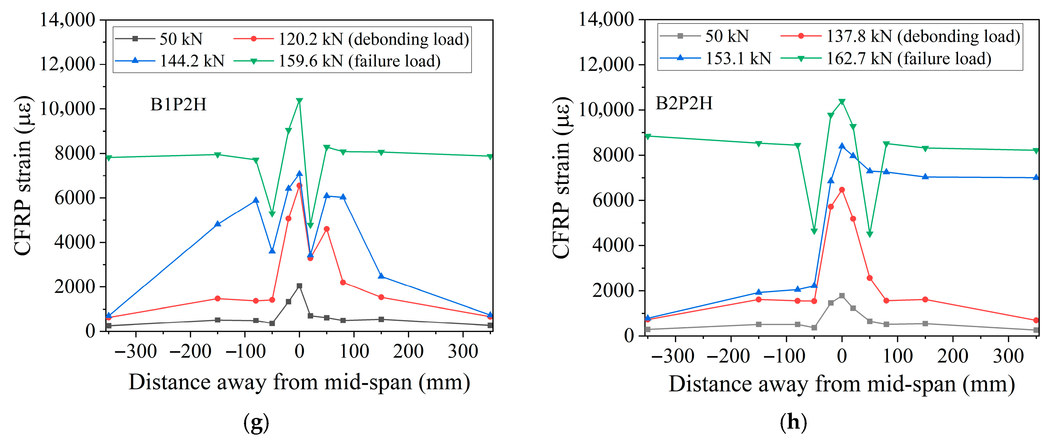
Experimental results indicate that the strain distribution patterns of the CFRP plates are generally consistent across different surface roughness treatments.
Figure 10 presents the strain distribution curves of the CFRP plates at various load levels for all specimens. It should be noted that one strain gauge near the end anchor of Specimen B2P2 failed in the later stage of loading; therefore, there is one missing data point in the curve under the failure load. As shown, all specimens exhibited stress concentration at the midspan crack. Under the same load, the CFRP strain gradually decreased from the midspan defect toward the plate ends. With increasing load, the stress concentration became more pronounced: when the load reached the adhesive cracking load at the CFRP–steel interface, the strains on both sides of the defect approached those at the midspan crack. As the load increased further, strains around the defect continued to rise, and the high-stress zone gradually extended toward the plate ends. When interfacial debonding approached the end anchor locations, strains farther from the midspan also increased significantly. However, due to the anchoring effect provided by the end anchors, the specimen can sustain the load continuously. At ultimate load, the CFRP plate was almost fully debonded along its length, and the strain distribution became relatively uniform. For the specimens without end anchors (B1 and B2), due to the long bonding length of the CFRP plates, after the first interfacial debonding occurred, the load dropped suddenly, but the CFRP plates did not debond completely, and the strengthened beams could still maintain their load-carrying capacity. However, when the load increased only slightly afterward, one end of the CFRP plates underwent complete debonding, and the strengthened beams finally lost their load-carrying capacity. As a result, the strain at the ultimate load showed a decreasing trend. In addition, compared with the specimens with end anchors, the high-strain areas of the specimens without end anchors were smaller and only concentrated in the mid-span region. These results demonstrate that end anchors effectively enhance the load-carrying capacity of the specimens and allow the high-strength potential of the CFRP plates to be fully utilized.
3.4. Failure Modes
The failure modes of strengthened beams with different surface roughness treatments were generally consistent. Taking the Sa3 sandblasted specimens as an example (
Figure 11), all specimens initiated debonding from the midspan prefabricated crack. As the load increased, instantaneous debonding occurred at the adhesive interface, causing a temporary drop in load. This behavior is primarily attributed to the relatively long bonded length of the CFRP plate; after instantaneous debonding, the interfacial cracks had not yet propagated to the plate ends, allowing the strengthened system to continue carrying load. For non-prestressed specimens with end anchors, failure was characterized by the CFRP plate being pulled out from the end anchors. In contrast, prestressed specimens, regardless of environmental exposure, exhibited a mixed failure mode combining CFRP rupture and end-anchor pullout. These results indicate that prestressed strengthening enables CFRP plates to fail in the material rather than solely by interfacial debonding, thereby significantly enhancing the utilization of the CFRP’s high-strength capacity at ultimate load.
As shown in
Table 3, the sandblasting grade has a significant influence on the interfacial debonding behavior of the strengthened beams.
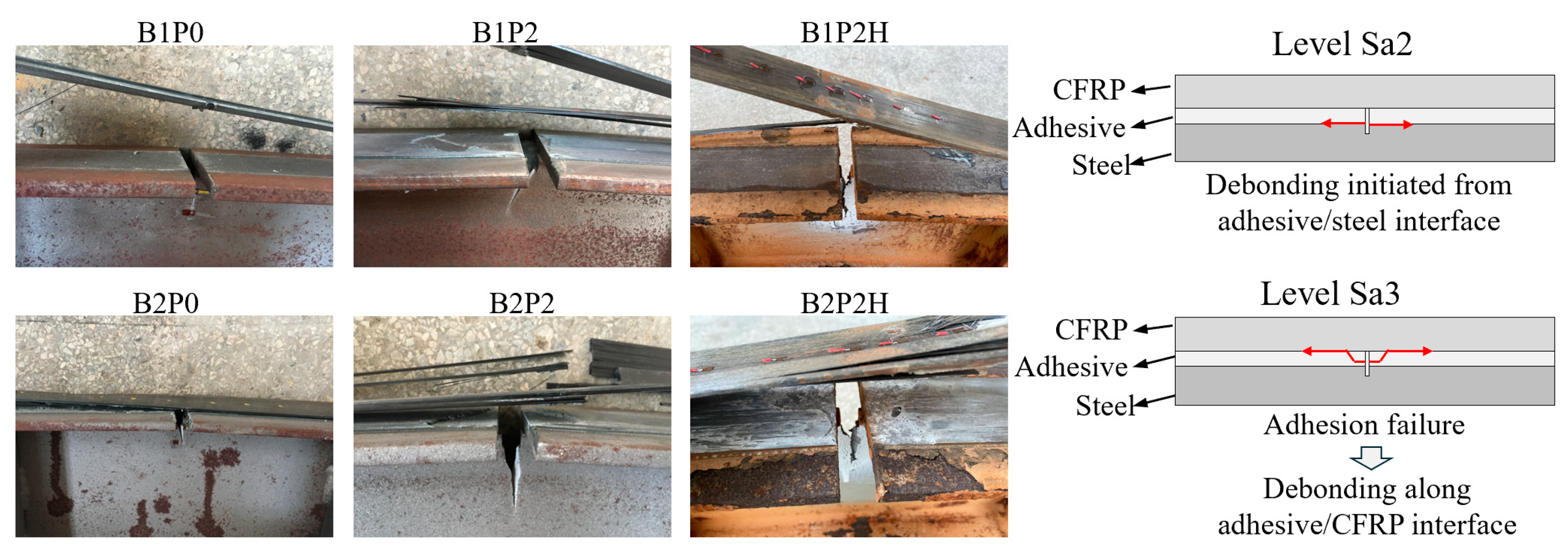
Figure 12 presents the local failure modes at the midspan crack: specimens with Sa2 treatment (B1P0, B1P2, B1P2H) primarily exhibited failure at the steel–adhesive interface, whereas specimens with Sa3 treatment (B2P0, B2P2, B2P2H) first experienced cohesive failure within the adhesive layer, followed by debonding at the CFRP–adhesive interface. From the perspective of interfacial formation mechanisms, the CFRP–adhesive interface constitutes a strong phase, whereas the steel–adhesive interface is a weak phase, making the steel/adhesive interface more susceptible to failure. Increasing the roughness of the steel bonding surface promotes the formation of an interlocking dentate structure between the adhesive and steel surface, thereby enhancing bond strength, improving interfacial cracking resistance, and altering the failure mode. After hygrothermal treatment, corrosive media penetrate more easily into the Sa2 interface compared with the higher-roughness Sa3 specimens, resulting in a more pronounced reduction in steel/adhesive bond strength and a decrease in adhesive cracking load. Comparison of the local failure in B1P2H and B2P2H shows rust formation at the bond interface in B1P2H, whereas B2P2H remained free of corrosion, indicating that a superior bonding interface helps resist the ingress of corrosive agents.
3.5. CFRP Strength Utilization
The strength utilization of CFRP plates is an important indicator for evaluating the effectiveness of CFRP in structural strengthening. In this study, the ratio of the midspan strain to the ultimate tensile strain of the CFRP plate (13,316 με, calculated from the data in
Table 2) is defined as the debonding utilization and ultimate utilization. For non-prestressed specimens, the initial strain is taken as zero, while for prestressed specimens, it corresponds to the strain after prestress application. The results are summarized in
Table 4. It should be noted that the calculation of CFRP ultimate utilization efficiency in
Table 4 does not account for the prestress loss of specimens after construction. As confirmed by the authors’ previous study [
6], specimens prestressed to 40% of the CFRP tensile capacity and anchored at the CFRP ends exhibited a negligible prestress loss of approximately 40 με over 100 days (corresponding to 0.73% of the initial prestress). The loss for specimens with 25% prestress in this study is expected to be even smaller and was therefore neglected. Although this omission may cause a slight overestimation, the results still reliably reflect the strengthening effect of CFRP prestress and end anchors under hygrothermal conditions.
In general, the surface roughness of steel has no significant effect on the strength utilization rate of CFRP plates in strengthened beams with end anchors. This is because the final failure mode of all strengthened beams in this study is determined by the end anchors. In the following sections, specimens with Sa3 surface roughness will be taken as an example to discuss the strength utilization rate of CFRP. For the specimen B2, the CFRP utilization at interface debonding was 41.5%, decreasing to 23.9% at complete debonding, due to the abrupt load drop after interface failure, which prevented the load from reaching the debonding threshold. In contrast, specimen B1, with more adequate adhesive curing, was able to sustain a load up to the ultimate capacity even after interface debonding, resulting in a significantly higher ultimate utilization. For specimens with end anchors, such as B2P0, the utilization at interface debonding and ultimate failure reached 58.4% and 76.0%, respectively, indicating that end anchors substantially enhance the ultimate utilization of CFRP plates. Prestressed strengthening further improved material efficiency: for specimen B2P2 with a 25% prestress level, CFRP utilization at interface debonding and ultimate load was 65.7% and 98.5%, representing increases of 12.5% and 29.6% compared with the non-prestressed specimen B2P0. This demonstrates that prestressing not only enhances utilization at interface debonding but also more significantly improves utilization of ultimate strength. After 90 days of hygrothermal cycling, specimen B2P2H exhibited utilizations of 65.7% and 95.1% at interface debonding and ultimate load, respectively. The decrease in utilization of ultimate strength is only 3.4% relative to B2P2, indicating that environmental effects have a limited impact on CFRP strength utilization.
4. Conclusions
This study investigated the flexural performance of CFRP-strengthened steel beams under hygrothermal conditions by conducting four-point bending tests on nine specimens with varying sandblasting grades (Sa2, Sa3), prestress levels (0%, 25% of CFRP ultimate tensile strength), and hygrothermal exposure durations (0 and 90 days). The effects and mechanisms of these variables on the strengthened beams were systematically analyzed, and the main findings are summarized as follows:
(1) End anchors effectively suppressed rapid failure following CFRP debonding, increasing the ductility coefficient by 3.1–3.7 times compared with unanchored specimens. When combined with 25% prestress of the CFRP ultimate tensile strength, the ultimate loads of specimens B1P2 (Sa2 grade) and B2P2 (Sa3 grade) increased by 26 kN and 16.1 kN, respectively, relative to non-prestressed specimens (specimens B1P0 and B2P0). The CFRP strength utilization reached 96.8–98.5%, fully exploiting the high-strength material properties and achieving a balance between structural safety and economic efficiency.
(2) Sa3 sandblasting created a “mechanical interlock + adhesive bonding” composite interface, resulting in adhesive cracking loads 11.1–19.1 kN higher than the purely adhesive Sa2 interface. After 90 days of hygrothermal aging, the cracking load of Sa3 specimens decreased by only 6.3%, considerably less than the 11.6% reduction observed for Sa2, and no interface corrosion occurred. In practice, for controllable steel beam damage, especially in hygrothermal environments, Sa3 grade sandblasting is recommended to enhance interfacial durability.
(3) Although hygrothermal cycling accelerates the degradation of the adhesive cracking load, its influence on ultimate load is minimal, with a maximum difference of only 1.9 kN, indicating that overall structural capacity remains controllable. In engineering applications, combining high-roughness surface treatment with end-anchored prestressed CFRP, together with enhanced interface sealing and protection measures, can further mitigate the adverse effects of hygrothermal exposure on interfacial performance.
