Abstract
This study presents an analytical investigation of the thermomechanical stability of hyperbolic doubly curved shells reinforced with graphene origami auxetic metamaterials (GOAMs) and resting on a Pasternak elastic foundation. The proposed model integrates shell geometry, thermal–mechanical loading, and architected auxetic reinforcement to capture their coupled influence on buckling behavior. Stability equations are derived using the First-Order Shear Deformation Theory (FSDT) and the principle of virtual work, while the effective thermoelastic properties of the GOAM phase are obtained through micromechanical homogenization as functions of folding angle, mass fraction, and spatial distribution. Closed-form eigenvalue solutions are achieved with Navier’s method for simply supported boundaries. The results reveal that GOAM reinforcement enhances the critical buckling load at low folding angles, whereas higher folding induces compliance that diminishes stability. The Pasternak shear layer significantly improves buckling resistance up to about 46% with pronounced effects in asymmetrically graded configurations. Compared with conventional composite shells, the proposed GOAM-reinforced shells exhibit tunable, folding-dependent stability responses. These findings highlight the potential of origami-inspired graphene metamaterials for designing lightweight, thermally stable thin-walled structures in aerospace morphing skins and multifunctional mechanical systems.
1. Introduction
Over the past few decades, engineers have made remarkable strides in developing high-performance structures, especially those based on shell geometries. Thanks to their curved shapes and efficient use of material, shell structures have become a popular choice across a wide range of applications—including aerospace, marine, civil, and mechanical engineering [1,2,3,4]. Among various shell forms, doubly curved shells stand out for their ability to carry external loads primarily through membrane action, which reduces bending stresses and improves structural efficiency. In particular, hyperbolic shells, with their saddle-shaped geometry formed by opposite curvatures in orthogonal directions, are especially effective at redistributing stresses and resisting buckling. These configurations are widely used in applications where lightweight performance and high structural reliability are essential—such as aerospace fairings, deployable space systems, morphing skins, submarine hulls, and innovative architectural designs. Their capability to withstand thermal gradients and complex loading conditions makes them well-suited for multifunctional and adaptive environments. The combination of stress-distributing behavior and inherent geometric stiffness allows hyperbolic shells to minimize deformation under load and enhance overall load-bearing capacity [5,6]. With the evolution of material science, traditional shells made from metals or monolithic composites have been increasingly replaced or enhanced with advanced material systems that offer superior mechanical, thermal, and multifunctional performance. Hence, numerous studies have been conducted about shell structures [7,8,9,10]. Composite materials have been introduced as a fundamental advancement in this domain. They consist of two or more constituent materials, typically fibers and a matrix, combined to achieve superior properties not attainable by the individual components alone. Fiber-reinforced composites, such as carbon fiber-reinforced polymers, have been widely utilized in shell structures to increase stiffness-to-weight ratios and improve fatigue performance. These composites enable the tailoring of directional stiffness and strength, allowing engineers to design shells that are structurally optimized for specific loading conditions [11,12,13]. In applications such as aerospace fuselages, automotive body panels, and wind turbine blades, composite shells have demonstrated exceptional performance and durability. To further extend the functionality of shell structures, nanocomposite materials have been introduced. Nanocomposites incorporate nanoscale reinforcements-such as carbon nanotubes (CNTs), graphene nanoplatelets (GNPs), or nano-silica particles-within the matrix phase of composites. These nanomaterials provide unique enhancements in mechanical, thermal, and electrical properties [14,15,16,17,18,19,20,21]. When applied to shell structures, nanocomposites offer increased toughness, improved thermal stability, and enhanced resistance to environmental degradation. The dispersion of nanoparticles throughout the matrix facilitates stress transfer at the nano level, thereby delaying crack initiation and propagation. Such improvements are particularly valuable in aerospace and marine environments, where shells are exposed to aggressive operating conditions. Moreover, the development of functionally graded materials (FGMs) has enabled a new generation of shell structures capable of responding adaptively to external stimuli. FGMs are engineered with gradual variations in composition and structure, leading to spatially varying material properties. In shell applications, FGMs are employed to manage thermal gradients, improve acoustic damping, and increase impact resistance. Their ability to reduce thermal stresses and suppress delamination makes them suitable for high-temperature environments, such as turbine components and reentry vehicles. Shells fabricated from FGMs exhibit superior performance in scenarios requiring both mechanical strength and thermal protection. Thus, nanocomposite structures attracted the researcher’s attention nowadays, and some of the recent contributions can be reviewed in Refs. [22,23,24].
A more recent and revolutionary class of advanced materials for shell structures involves architected metamaterials, particularly those based on origami-inspired geometry. One such example is graphene origami auxetic metamaterials (GOAMs), which combine the exceptional properties of graphene with the mechanical adaptability of origami structures and the counterintuitive behavior of auxetic materials. GOAMs are composed of folded graphene-based units that exhibit a negative Poisson’s ratio, meaning they expand laterally when stretched and contract when compressed [25,26]. This auxetic behavior enhances energy absorption, shear resistance, and fracture toughness. The integration of GOAMs into shell structures introduces multiple advantages. Due to the foldable architecture, GOAMs can provide tunable stiffness and deformation patterns, allowing the shell to adapt dynamically to varying load conditions. This property is especially beneficial in morphing structures and deployable systems, where shape adaptability is crucial. Furthermore, the lightweight nature of graphene, combined with its high tensile strength and thermal conductivity, ensures that GOAM-reinforced shells maintain structural integrity under extreme mechanical and thermal loads. The layered and foldable design enables multi-scale interaction within the shell, enhancing overall performance without significant weight penalties. Applications of GOAM-reinforced shells are being explored in next-generation aerospace skins, flexible robotics, and energy-absorbing components. In aerospace, for instance, GOAMs are considered for use in adaptive fuselage panels and high-performance fairings. In civil engineering, they may be integrated into seismic-resistant structural elements, where their auxetic response can be leveraged to dissipate dynamic energy. Additionally, due to their electrical conductivity and large surface area, GOAMs offer potential for integration in smart shells equipped with sensing and actuation capabilities. The unique combination of negative Poisson’s ratio, foldability, and exceptional material properties allows GOAMs to transcend the limitations of conventional reinforcements. When designed appropriately, they enable shell structures to achieve unprecedented levels of multifunctionality, combining mechanical strength with adaptability, responsiveness, and intelligence. This positions GOAM-based shells at the forefront of structural innovation, particularly for environments requiring resilience, tunability, and lightweight performance. The fusion of advanced materials such as fiber-reinforced composites, nanocomposites, FGMs, and GOAMs with shell structures represents a transformative shift in engineering design. These innovations are not merely incremental; they signify a paradigm change in how structural components are conceived and utilized. Through careful integration of geometry, material science, and mechanics, future shell structures are expected to meet the demanding requirements of high-performance systems across aerospace, biomedical, automotive, and civil sectors. The most recent works in this field can be observed in Refs. [27,28,29].
The accurate prediction and control of buckling behavior in hyperbolic shells is of paramount importance due to their pronounced sensitivity to compressive and thermomechanical loading. Unlike flat or singly curved panels, hyperbolic shells exhibit complex instability patterns that can be triggered by relatively low perturbations, particularly in the presence of thermal gradients or uneven support conditions. A comprehensive understanding of their buckling characteristics allows for the design of lighter and more efficient structures without compromising safety. Additionally, since many advanced applications-such as aerospace skins and morphing components-operate under variable environmental conditions, ensuring buckling stability under both mechanical and thermal loads becomes essential. The interplay between geometry, material anisotropy, and foundation support must therefore be rigorously modeled to capture the nuanced behavior of these shells and to fully harness their structural potential in next-generation engineering systems. Other important works in this field can be found in Refs. [30,31,32,33,34]. Recent works have also explored origami- and auxetic-inspired metamaterials in different contexts, including structural stability and multifunctional applications [35,36,37]. However, these studies have not addressed hyperbolic shells reinforced with GOAMs. In contrast, the present paper develops, for the first time, an analytical framework for the thermomechanical buckling of hyperbolic doubly curved shells with GOAM reinforcement on Winkler–Pasternak foundations, thereby extending the scope of origami metamaterials into curved geometries.
The motivation behind this study stems from the noticeable lack of analytical models that can accurately capture the complex buckling behavior of hyperbolic doubly curved shells reinforced with advanced architected materials-particularly GOAMs-when subjected to thermal loading and supported by elastic foundations. Although significant progress has been made in the analysis of composite and nanocomposite shells, the unique mechanical behavior of foldable metamaterial systems with tunable properties remains largely underexplored. In contrast to our earlier studies on graphene nanoparticle-reinforced nanocomposites, the present work focuses on GOAMs, which differ fundamentally in architecture, deformation mechanism, and tunable auxetic response. Moreover, while most prior GOAM research has dealt with flat plates or beams, the present study is, to the best of our knowledge, the first to address the thermomechanical buckling of hyperbolic doubly curved shells on Winkler–Pasternak foundations, thereby extending the scope of origami-inspired metamaterials into curved geometries. In particular, the combined effects of GOAM distribution patterns, folding mechanics, and the interaction between thermal loads and foundation stiffness have not yet been comprehensively addressed in the existing literature. This reveals a clear research gap: the need for a unified, physically consistent model that can evaluate the thermomechanical stability of GOAM-integrated shells. The analytical framework developed in this work directly supports the design and optimization of high-performance structural components operating under mechanical and thermal stress. Potential applications include thermally stable aerospace fairings, adaptive panels in morphing airframes, deployable space structures, vibration-damping components in precision instruments, and energy-absorbing civil structures like seismic shields. By enabling spatial control over stiffness, thermal expansion, and deformation characteristics through tailored GOAM distribution, the proposed model lays the groundwork for the next generation of lightweight, multifunctional, and intelligent structural systems.
2. Analytical Framework and Stability Formulation
The structure under investigation is a novel hyperbolic curved panel that has a saddle-shaped geometry and is integrated with GOAMs and subjected to a uniform thermal environment. This panel is assumed to be supported by a two-parameter Pasternak-type elastic foundation, which is modeled by incorporating a combination of normal (Winkler-type) springs and a shear-interacting layer to more accurately simulate subgrade reactions. The thermal loading is considered to be spatially uniform across the entire panel. A schematic representation of the geometrical configuration is illustrated in Figure 1. In this figure, the panel thickness is denoted by h, while and represent the principal radii of curvature in the longitudinal and transverse directions, respectively. Noted that for a hyperbolic doubly curved shell, . The in-plane dimensions of the panel are given by the length a and the width b, as indicated.
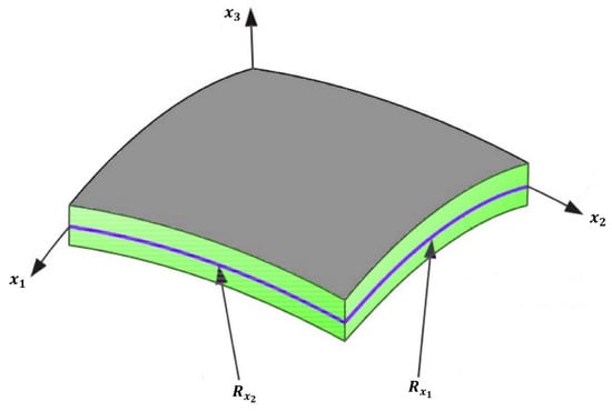
Figure 1.
Schematics of the hyperbolic curved panel.
In the present study, the effects of transverse shear deformation are taken into consideration to improve the accuracy of the analytical results, particularly for moderately thick shells where classical assumptions may lead to significant errors. To this end, the displacement field is formulated based on the FSDT. Unlike classical plate theory, which neglects shear deformation and is limited to thin structures, FSDT incorporates a linear distribution of transverse shear strains, making it more suitable for composite and moderately thick curved panels such as the one investigated in this work. Moreover, while higher-order shear deformation theories can provide improved accuracy by modeling a parabolic shear strain distribution without requiring shear correction factors, they often involve increased mathematical complexity and computational effort. FSDT offers a favorable balance between accuracy and simplicity, making it a widely accepted and computationally efficient choice for stability analysis of curved composite structures with non-negligible thickness. In the present study, the effects of transverse shear deformation are taken into account to enhance the accuracy of the analytical predictions. Hence, the displacement field is formulated based on the FSDT, which expresses the components of displacement as follows [38]:
The displacement of an arbitrary point located on the shell surface along the x1, x2, and x3 directions is denoted by ux1, ux2, and ux3, respectively. The corresponding displacement components of the shell’s mid-surface in these directions are represented by u, v, and w. Furthermore, the terms ψx1 and ψx2 denote the rotations of the normal to the mid-surface about the x2- and x1-axes, respectively. Also:
The strain components, in accordance with the FSDT, can be expressed in terms of the displacement field as follows:
The virtual displacement principle, also known as the principle of virtual work, is a fundamental concept in continuum mechanics and structural analysis. It states that a mechanical system is in equilibrium if the virtual work performed by the internal forces is exactly balanced by the virtual work performed by the external forces for any kinematically admissible virtual displacement. In the context of structural analysis, this principle allows the derivation of the governing equilibrium equations without directly invoking Newton’s laws, by instead using energy considerations. Specifically, one assumes small virtual (imaginary) displacements that are consistent with the system’s boundary conditions. Then, the variation (or virtual change) of the total potential energy—which includes the strain energy stored in the structure and the work performed by external forces—is set to zero. This leads to a set of differential equations representing the conditions for equilibrium. This principle is especially useful for complex structures such as curved shells, composite materials, and systems with elastic foundations, where direct force-based methods would be mathematically intractable. Thus, the governing equilibrium equations are derived by employing the principle of virtual displacements, wherein variations in both the internal strain energy and the external work are introduced into the formulation. By enforcing that the total virtual work associated with these variations vanishes, the equilibrium conditions of the system are obtained [39]:
To derive the governing equations, the strain energy of the system must first be formulated. For this purpose, the following expression is employed to represent the total strain energy stored within the structure [40]:
The variation in this strain energy expression, when combined with the corresponding variation in external work, leads to the following governing equation:
Note that although the GOAM-reinforced panel is conceived as a laminated configuration, the governing relations are expressed in equivalent single-layer form with homogenized effective properties.
The external virtual work consists of three main contributions: the reactive forces from the Pasternak-type elastic foundation, the thermal loading effects, and the applied mechanical in-plane loads.
The virtual work associated with the Pasternak foundation can be expressed as follows [41]:
In this expression, the Laplacian operator is denoted by ∇2, while the parameters KW and KG represent the stiffness of the Winkler-type springs and the shear layer of the Pasternak foundation, respectively [42].
One possible approach for evaluating the virtual work associated with the thermal load is through the following expression [43,44]:
In this expression, the thermal loads in the x1 and x2 directions are denoted by and , respectively, and are defined as follows [45]:
To evaluate the virtual work corresponding to the applied mechanical in-plane loads, the following expression is employed:
In this expression, the mechanical in-plane loads acting in the x1 and x2 directions are denoted by and , respectively.
By expressing the strain components in terms of the displacement field and introducing the corresponding stress resultants, the equilibrium equations can be derived through the application of variational calculus. These equations, formulated in terms of the stress resultants, are obtained as follows:
The following equations define the stress resultants employed in the preceding equilibrium relations:
In the above expressions for the stress resultants, the shear correction factor associated with the FSDT is denoted by κs. Additionally, the integral coefficients appearing in the above relations are defined as follows:
At this stage, the actual values of the mechanical properties corresponding to the hyperbolic doubly curved panel are evaluated. Under the influence of a thermal environment, the constitutive relations that govern the thermo-mechanical behavior of the panel can be formulated as follows [46]:
In the presented formulation, the stress and strain tensors are denoted by and ε, respectively. The stiffness coefficients, coefficient of thermal expansion, and temperature increment are represented by , α, and ΔT, respectively. The individual components of the stiffness matrix are defined using the following relations [47]:
GOAMs have been recognized as a novel class of architected materials that combine the exceptional mechanical and thermal characteristics of graphene with the geometrical versatility of origami-inspired designs and the unusual deformation behavior of auxetic structures. These metamaterials are typically formed by embedding patterned graphene sheets into folded configurations that exhibit negative Poisson’s ratio responses. As a result, an auxetic behavior is achieved, whereby lateral expansion occurs under uniaxial tensile loading, and lateral contraction is observed under compression. This unconventional deformation mechanism has been associated with enhanced shear resistance, improved indentation toughness, and superior energy absorption capacity. Due to the foldable nature of their origami-inspired architecture, GOAMs are capable of exhibiting a programmable mechanical response, which can be tuned by altering fold angles, distribution patterns, and unit cell geometries. Through this geometric flexibility, mechanical stiffness and deformation modes can be adjusted to meet specific functional requirements. Furthermore, the inherent strength and stiffness of graphene allow these materials to achieve an extremely high strength-to-weight ratio, making them attractive for lightweight structural applications, particularly in aerospace and high-performance mechanical systems. The high thermal conductivity and thermal stability of graphene have also enabled GOAMs to maintain structural performance in elevated temperature environments, while simultaneously offering potential benefits in passive thermal management. In addition, the multifunctional nature of graphene, coupled with the auxetic and reconfigurable behavior of the origami design, has allowed GOAMs to be considered as promising candidates for use in smart structures, morphing components, and thermally adaptive systems. Their capability to provide direction-dependent stiffness and thermal tunability has made them especially suitable for integration into curved shell structures subjected to complex mechanical and thermal loading conditions. Consequently, GOAMs have been increasingly explored for applications in fields such as aerospace, soft robotics, bioinspired devices, and multifunctional metamaterials.
The effective mechanical properties of the GOAMs utilized in the proposed structure are examined in the following formulation. In order to determine the equivalent Young’s modulus of elasticity, which characterizes the overall in-plane stiffness of the metamaterial-reinforced system, the following relation is employed [28]:
In this formulation, denotes the effective Young’s modulus of the GOAMs, while represents a modifying function, the specific form and characteristics of which will be discussed in a subsequent section. The parameter is associated with material properties that are determined by the intrinsic characteristics and geometric configuration of the GOAMs. These properties play a critical role in defining the effective mechanical response of the metamaterial within the overall composite system [45]:
Since the reinforcement and matrix phases together constitute the entire volume of the composite system, the sum of their respective volume fractions must equal unity, irrespective of the specific formulation or representation employed. Accordingly, the volume fraction of the GOAM phase, denoted by , can be evaluated using the following expression:
In this context, denotes the weight fraction of the GOAM phase. It is also noted that in the subsequent formulations, VM refers to the volume fraction of the matrix phase. As the GOAMs and the matrix collectively occupy the entire volume, their respective volume fractions are complementary, and their sum is equal to unity. The GOAM-reinforced panel is modeled as a laminated structure, and the volume fraction of the GOAMs in the k-th layer, denoted by , is determined by the following relation [25]:
To estimate the overall thermo-mechanical behavior of composite structures, the rule of mixtures is commonly adopted as a micromechanical modeling approach. Within this method, it is assumed that the effective properties of the composite material can be approximated as weighted averages of the properties of the individual constituent phases, typically based on their respective volume fractions. This approach provides a simple yet efficient means for estimating key parameters such as elastic stiffness, thermal conductivity, and the coefficient of thermal expansion, particularly in cases where the interaction between phases is relatively uniform and the bonding is assumed to be ideal. Although the method is based on simplifying assumptions, it has been widely utilized due to its broad applicability across various engineering materials and its ability to deliver reasonably accurate predictions for initial design, analysis, and optimization tasks.
Accordingly, in order to obtain accurate estimates of the additional thermo-mechanical properties associated with the proposed model, the following relations are employed:
In addition, the correction functions utilized in Equations (36), (40), and (41) are defined as follows [25]:
In which, is the GOAM’s folding degree, which ranges from 0 to 100%. Moreover, is the temperature and is the ambient temperature.
Four distinct metamaterial distribution patterns are considered in the present study. The mathematical expressions corresponding to these distribution modes are given as follows [28]:
where is the F coverage of GOAMs. The larger is the more GOAM is folded.
3. Eigenvalue Formulation and Solution Strategy
In the present study, Navier’s solution approach has been employed to determine the critical buckling loads of hyperbolic doubly curved shells. This method is based on the assumption that the displacement fields can be represented using double Fourier series expansions, which are constructed to satisfy the simply supported boundary conditions along all edges of the shell. By expressing the displacement components in the form of trigonometric functions, typically sine and cosine terms, the governing partial differential equations are transformed into a set of algebraic equations in terms of unknown Fourier coefficients. As a result, the complex differential stability problem is significantly simplified into an eigenvalue problem, which enables the determination of critical buckling loads in a systematic and computationally efficient manner. One of the principal advantages of Navier’s approach lies in its ability to provide closed-form or semi-analytical solutions for structures with regular geometries and simple boundary conditions. In the case of hyperbolic doubly curved shells, where analytical treatment becomes challenging due to curvature-induced coupling and geometric nonlinearity, the application of Fourier-based expansions allows for an accurate approximation of the displacement field while maintaining mathematical tractability. Furthermore, since the series functions inherently satisfy boundary conditions, the focus can be directed toward the solution of the governing equations without the need for auxiliary constraint enforcement. This results in enhanced numerical stability and reduced computational cost, particularly in problems involving buckling under thermal and mechanical loads. For these reasons, Navier’s method has remained a reliable and widely accepted analytical tool in the stability analysis of curved shell structures. According to Navier’s solution technique, the displacement fields are formulated such that the simply supported boundary conditions along the edges of the shell are inherently satisfied. Consequently, the displacement components can be represented in the following form [39]:
where
It should be noted that the use of Navier’s trigonometric series ensures that the simply supported boundary conditions are satisfied identically, with zero transverse deflection and vanishing bending moments enforced at the edges by construction [48,49].
In this formulation, m and n denote the longitudinal and transverse wavenumbers, respectively. By substituting the Fourier series expressions from Equations (46)–(49) into the equilibrium equations, and by introducing the mechanical in-plane load as , an eigenvalue problem is obtained. The non-trivial solutions of this eigenvalue problem correspond to the critical buckling loads of the structure.
In this eigenvalue formulation, [Ke] represents the elastic stiffness matrix, while [Kg] denotes the geometric stiffness matrix associated with the in-plane loading. The vector {X} corresponds to the displacement amplitudes derived from the assumed Fourier series expansions. The stability criterion is formulated as a generalized eigenvalue problem, in which the smallest eigenvalue corresponds to the onset of buckling, i.e., loss of stability occurs when the lowest eigenvalue vanishes.
4. Results and Discussion
In this section, the critical buckling behavior of the proposed hyperbolic doubly curved shells reinforced with GOAMs is examined under various thermomechanical loading conditions. The analytical framework, developed based on the FSDT and solved using Navier’s solution approach, has been utilized to conduct a comprehensive parametric study. Key influencing parameters—including thermal loading intensity, GOAM distribution patterns, curvature radii, foundation stiffness coefficients, and layer-wise metamaterial configuration—have been systematically varied to investigate their effects on the critical buckling loads.
The accuracy of the proposed model is first validated against benchmark solutions available in the literature, ensuring the reliability of the analytical approach. To verify the accuracy and reliability of the present analytical formulation, a comparative validation study has been carried out. The normalized critical buckling loads of a cylindrical shell are computed and presented in Table 1. These results are compared with those reported in three independent references: Ref. [50], Ref. [51], and Ref. [24]. The cylindrical shell considered in this phase is an FG structure, with the corresponding material gradation relations adopted from Ref. [52]. The mechanical properties of the constituent phases are given as: Ec = 151 GPa, νc = 0.3, ρc = 3000 kg/m3 for the ceramic, and Em = 70 GPa, νm = 0.3, ρm = 2707 kg/m3 for the metallic phase. The normalized critical buckling load is defined as , and the cylindrical configuration is obtained by setting the transverse radius of curvature tend to infinity, i.e., Rx2→∞. As observed in Table 1, the results obtained from the present model exhibit excellent agreement with the reference studies across various slenderness ratios (a/h). The maximum deviation observed between the present results and those of Refs. [24,50,51] is within 2.5%, which is well within acceptable bounds for analytical modeling. For instance, at a/h = 10, the present result differs from Ref. [50] by only +0.32%, from Ref. [51] by −0.31%, and from Ref. [24] by +0.03%. Similar levels of agreement are evident for other values of a/h, with deviations generally below 1%. These minor differences may be attributed to the use of different shear deformation theories, boundary assumptions, or solution strategies across the compared works.

Table 1.
Validation of the results with earlier published simpler work.
The close correspondence between the present results and previously published data confirms the validity and robustness of the developed analytical approach, thereby establishing confidence in its application to more complex geometries such as hyperbolic doubly curved shells reinforced with GOAMs under thermomechanical loading.
The cylindrical case was selected for validation because reliable benchmark solutions exist, while comparable results for hyperbolic shells reinforced with GOAMs are not yet available in the literature. To further support the algorithm, a reference thermoelastic case of a homogeneous shell under uniform heating was also analyzed, and the predicted buckling thresholds were found to be consistent with classical thermoelastic stability results, confirming that the present method remains reliable under purely thermal loading.
The effect of the GOAMs on the critical buckling loads of the proposed hyperbolic doubly curved shell is investigated in Figure 2, where the variations in critical buckling loads are illustrated with respect to different weight percentages of the GOAM phase and its folding degrees. The results are presented for three distinct distribution configurations of the GOAMs: VGr-U, VGr-X, and VGr-A. It is observed that an increase in the GOAMs’ weight percentage generally leads to a monotonic enhancement in the critical buckling load across all configurations when the folding degree is set to 0%. This trend is attributed to the significant mechanical contribution of the GOAMs, which act as stiffening reinforcements within the composite shell structure. As the weight percentage increases, the relative share of the auxetic phase rises, resulting in improved in-plane and out-of-plane stiffness. The auxetic nature of the GOAMs, characterized by a negative Poisson’s ratio, allows for better stress distribution under compressive loading, thereby delaying the onset of instability. The folding degree of the GOAM microstructure is also found to exert a notable influence on the structural stability. As the folding degree increases, a nonlinear rise in the critical buckling load is detected. This behavior may be explained by the fact that increased folding induces additional geometric complexity and microstructural interlocking, both of which enhance the resistance of the metamaterial against deformation. Folded configurations enable a more effective load transfer between the matrix and the reinforcement, while simultaneously altering the deformation pathway of the shell, thus increasing its buckling capacity. Among the three studied configurations, the VGr-A yields the highest critical buckling loads for equivalent GOAM content and folding degree, followed by the crosswise and uniform arrangements. This result implies that strategically placing the GOAMs in regions of high stress sensitivity—rather than distributing them uniformly—can more effectively suppress buckling. The superior performance of the asymmetric layout can be physically interpreted as a result of localized reinforcement that better counteracts instability modes that typically initiate at specific regions of curvature-induced stress concentration. These findings underscore the potential of GOAM-based design strategies in tailoring the mechanical response of curved composite shells, particularly for applications where thermal and mechanical stability are critical. By judiciously controlling the metamaterial configuration and deployment, designers can achieve significant performance gains without considerable increases in weight or material cost.
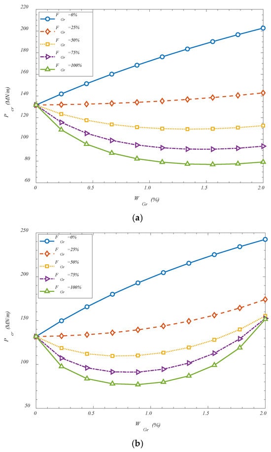
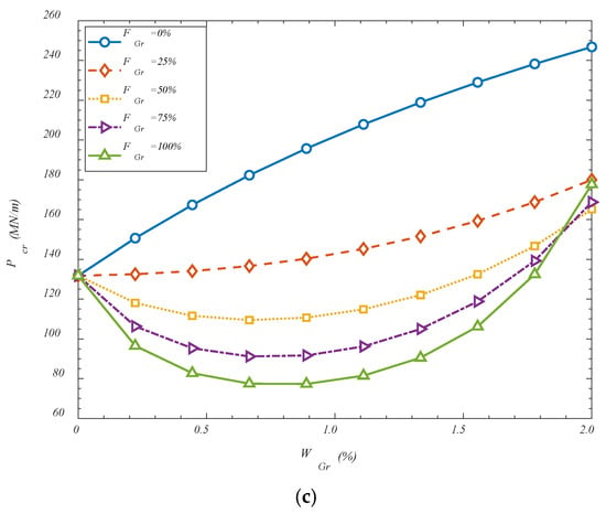
Figure 2.
Effect of GOAMs’ weight percentage and folding degree on the critical buckling loads for (a) VGr-U; (b) VGr-X; (c) VGr-A.
The effect of the metamaterial distribution patterns, their weight percentage, and folding degree is investigated in Figure 3. Similar to previous figure, it is observed that increasing the folding degree, leads the critical buckling loads to reduce. Although GOAMs are known for their potential to enhance structural stability, it has been observed in some configurations that increasing the folding degree can lead to a reduction in the critical buckling load. This behavior can be explained by considering the mechanical implications of excessive folding on the structural integrity of the reinforcement phase. As the folding degree increases, the overall continuity and in-plane stiffness of the GOAM network may become compromised due to the introduction of sharper geometrical discontinuities and more localized deformation zones. These highly folded configurations tend to exhibit increased flexibility and out-of-plane deformability, which may reduce their effectiveness in resisting global compressive loads. Furthermore, at higher folding degrees, the alignment between the GOAM microstructure and the primary load paths of the shell can become less efficient, causing a portion of the applied load to be absorbed through non-structural deformation modes such as twisting or localized bending. This redistribution of stress away from the load-bearing directions can lead to a premature onset of instability. Additionally, the folded architecture, while beneficial for energy absorption and local adaptability, may reduce the effective cross-sectional area contributing to axial stiffness, thereby diminishing the shell’s overall capacity to resist buckling. Therefore, while moderate folding can introduce beneficial auxetic behavior and controlled stiffness enhancement, excessive folding may instead introduce compliant mechanisms that undermine the shell’s ability to sustain compressive loads, ultimately resulting in lower critical buckling thresholds. Also, the contrasting influence of the GOAM weight percentage on critical buckling loads at different folding degrees can be explained by examining the interaction between the material’s effective stiffness and its structural geometry. When the folding degree is set to zero, the GOAM phase behaves similarly to a planar or nearly flat reinforcement layer. In this configuration, increasing the GOAM weight percentage directly increases the overall stiffness of the composite shell due to the superior mechanical properties of graphene-based auxetic metamaterials. The reinforcement is able to align effectively with the load paths, leading to improved load-bearing capacity and, consequently, enhanced critical buckling resistance. However, when the folding degree reaches 100%, the mechanical role of the GOAM phase changes fundamentally. At such high folding levels, the microstructure becomes highly corrugated, introducing significant geometric nonlinearity and local flexibility. Although more material is present as the weight percentage increases, a larger portion of this material becomes geometrically ineffective in resisting global compressive loads. Instead of contributing to in-plane stiffness, the folded GOAM regions are prone to local bending, twisting, or unfolding-type deformations that absorb energy without offering substantial resistance to buckling. As a result, the structural benefit of additional GOAM content is diminished or even reversed. Moreover, increasing the GOAM weight percentage at high folding degrees introduces a larger volume of flexible, folded microstructure, which can act as mechanical imperfections or localized soft zones. These regions may amplify instability by introducing stress concentrations or altering the global deformation pattern of the shell. Therefore, while the material content is increased, the effective stiffness in the load-bearing direction may be reduced, leading to a decrease in the critical buckling load. This behavior underscores the importance of coupled optimization between the material distribution and geometric configuration of the metamaterial phase. Simply increasing the quantity of GOAMs does not guarantee improved performance—particularly when the geometric folding alters the mechanical response in a non-beneficial manner.
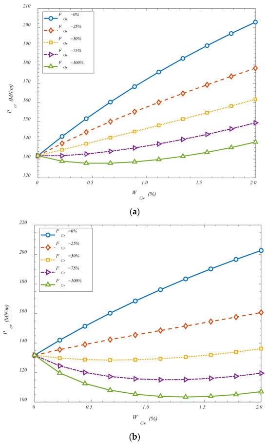
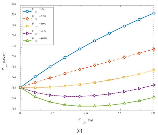
Figure 3.
Effect of GOAMs’ weight percentage and folding degree on the critical buckling loads for (a) FGr-X; (b) FGr-O; (c) FGr-A.
The effect of GOAMs’ aspect ratio is considered in Figure 4. It is observed that an increase in the ratio of GOAM length to its thickness has been found to enhance the critical buckling load of the reinforced shell structure. This behavior can be attributed to the shift in the mechanical role of the GOAM phase as it becomes slenderer. When the length of the GOAM unit is increased relative to its thickness, the reinforcement layer behaves more like an extended membrane or plate element, contributing more effectively to in-plane stiffness and axial load transfer. In such cases, the GOAMs are capable of engaging a greater surface area of the shell, thereby distributing stresses more uniformly and suppressing localized instability. Moreover, thinner GOAMs are less likely to introduce concentrated stiffness discontinuities that could act as stress risers under compression. As the thickness is reduced, the reinforcement conforms more naturally to the curvature of the shell, maintaining geometric compatibility with the host structure and enhancing composite action. In this regime, the benefits of auxetic behavior—such as lateral expansion under axial strain—are more efficiently translated into buckling resistance, as the structure is able to resist deformation through coordinated in-plane mechanisms rather than local bending or shear. Thus, the increase in the length-to-thickness ratio improves the reinforcement efficiency of the GOAM layer, enabling it to contribute more directly to the global stability of the system. This enhanced structural engagement leads to higher critical buckling thresholds, particularly in shells operating under thermomechanical conditions.
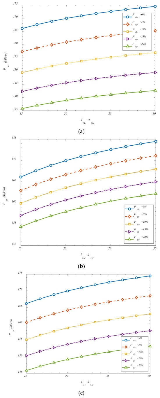
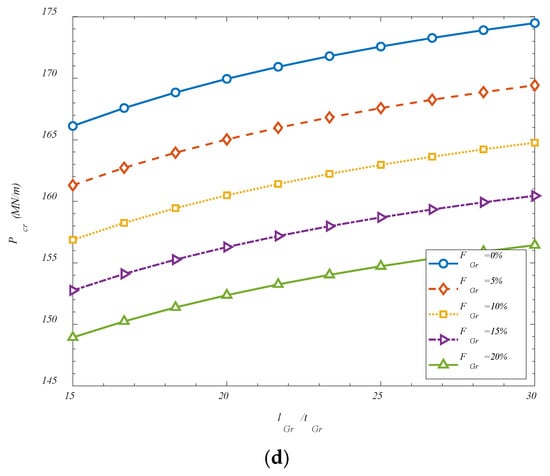
Figure 4.
Effect of GOAMs’ geometric and folding degree on the critical buckling loads for (a) FGr-U; (b) FGr-X; (c) FGr-O; (d) FGr-A.
Also, a similar effect, but for various values of GOAMs’ weight percentage is considered in Figure 5 which confirms the earlier findings.
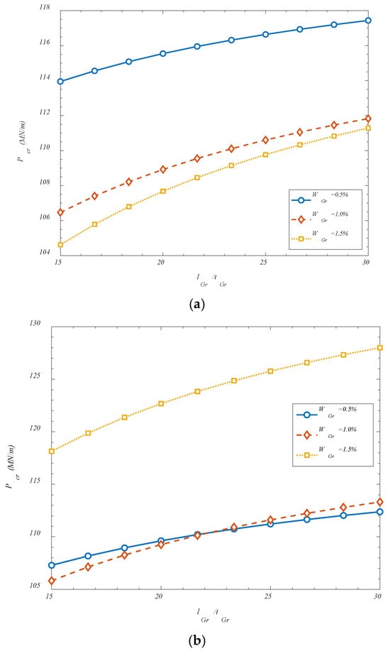
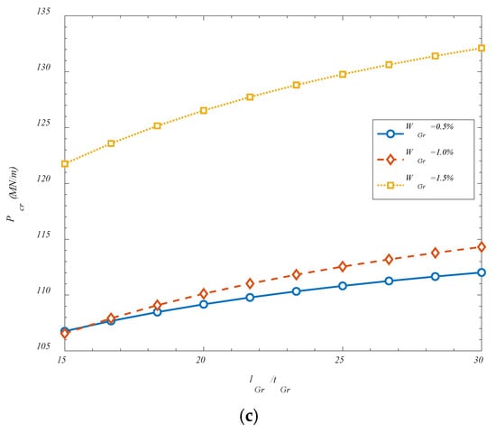
Figure 5.
Effect of GOAMs’ weight percentage and geometrics on the critical buckling loads for (a) VGr-U; (b) VGr-X; (c) VGr-A.
Figure 6 investigates the effect of temperature changes and also, the panels aspect ratio on the critical buckling loads. It is found that a reduction in the critical buckling load has been observed with increasing temperature difference across the shell, and this trend can be attributed to the thermomechanical effects induced within the composite system. As the temperature difference increases, additional thermal stresses are generated due to the mismatch in thermal expansion between the GOAMs and the surrounding matrix material. These thermally induced stresses act in conjunction with the applied mechanical loads and contribute to a preloading condition that brings the structure closer to its instability threshold. Moreover, elevated thermal fields tend to reduce the effective stiffness of the constituent materials, particularly in polymers or composites, leading to a softened structural response. The combined effect of thermal pre-stressing and material degradation under thermal loading causes the shell to become more susceptible to buckling, thereby lowering the critical buckling load. Additionally, it has been found that increasing the length-to-thickness ratio (a/h) from 5 to 15 leads to a pronounced decrease in buckling strength. This behavior is fundamentally associated with the increasing slenderness of the shell structure. As the shell becomes longer and thinner, its flexural rigidity relative to its axial length diminishes, and the structure behaves more like a plate with reduced resistance to compressive loads. In slender shells, the deformation modes tend to localize more easily, and global instability is triggered at lower loads due to reduced bending and shear resistance. Furthermore, geometric imperfections and localized variations in stiffness—particularly in heterogeneous systems such as GOAM-reinforced shells—are more likely to affect slender structures, further compromising their stability. As a result, the increase in slenderness significantly lowers the load required to initiate buckling. These findings highlight the strong sensitivity of structural stability to both thermal environments and geometric proportions, and they underscore the importance of accounting for such parameters in the design of lightweight and thermally exposed shell systems.
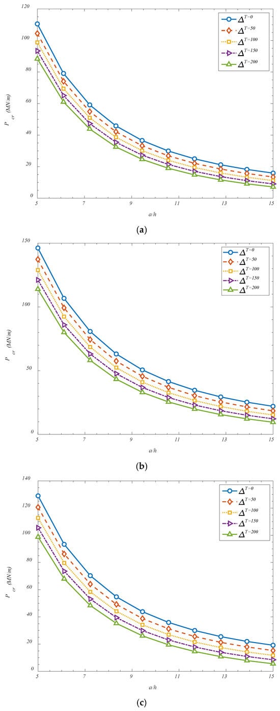
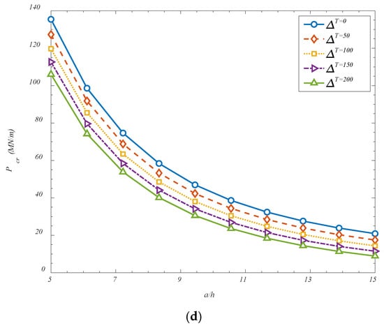
Figure 6.
Effect of temperature variations and shell’s thickness on the critical buckling loads for (a) FGr-U; (b) FGr-X; (c) FGr-O; (d) FGr-A.
In Figure 7, the effect of curvature radius-to-panel’s length is also considered. It has been observed that an increase in the ratio of the curvature radius along the longitudinal direction (Rx1) to the panel’s length (a) results in a reduction in the critical buckling load. This behavior can be physically explained by considering the role of geometric curvature in stabilizing shell structures. In hyperbolic or doubly curved shells, curvature contributes significantly to the global stiffness and stability characteristics. A shell with pronounced curvature (i.e., smaller Rx1) exhibits increased geometric coupling between in-plane and out-of-plane deformations, which enhances its resistance to buckling under compressive loading. As the ratio Rx1/a increases, the shell becomes geometrically flatter in the longitudinal direction, gradually approaching the behavior of a cylindrical or even a plate-like structure. In this flattened configuration, the inherent geometric stiffness provided by the curvature is diminished, and the shell becomes more prone to instability under axial or in-plane compressive forces. The reduction in curvature weakens the shell’s ability to redistribute stresses through membrane action, which is one of the principal stabilizing mechanisms in curved structures. As a result, the shell relies more heavily on bending stiffness to resist buckling—an unfavorable condition, particularly in thin-walled configurations where bending stiffness is relatively low. Additionally, in flatter shells, the deformation modes tend to involve larger deflections and lower energy barriers to instability, leading to a decrease in the critical load threshold. The curvature radius effectively acts as a geometric stiffener; when it is reduced (i.e., curvature increases), the shell is better equipped to sustain compressive stresses without undergoing instability. Therefore, increasing Rx1/a compromises this effect, and a reduction in the critical buckling load is consequently observed. This observation reinforces the importance of curvature in shell design and highlights how even moderate changes in geometric ratios can significantly affect the stability performance of advanced metamaterial-reinforced shell structures.
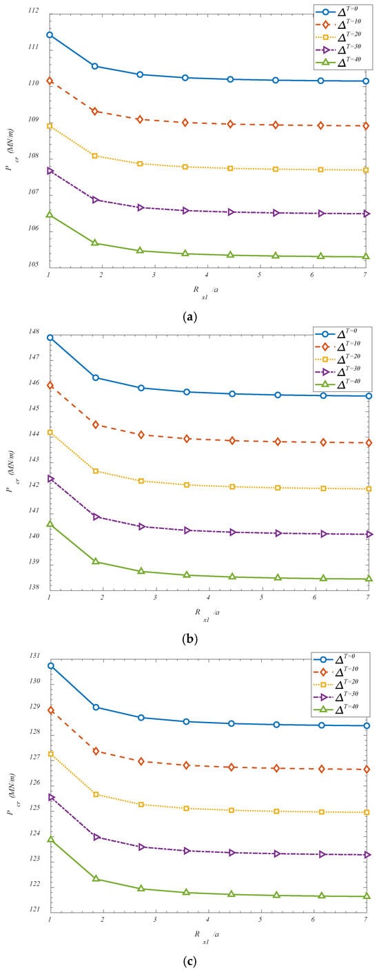
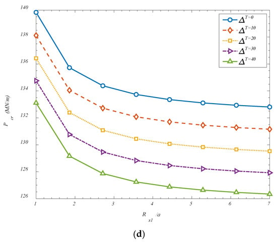
Figure 7.
Effect of temperature variations and aspect ratio of the panel on the critical buckling loads for (a) FGr-U; (b) FGr-X; (c) FGr-O; (d) FGr-A.
The critical buckling response of the GOAM-reinforced hyperbolic shell has been examined under varying values of the Pasternak-type elastic foundation parameters, including the Winkler spring stiffness KW and the shear layer modulus KG, as presented in Table 2, Table 3, Table 4, Table 5, Table 6 and Table 7. The results are reported for multiple buckling modes defined by longitudinal and transverse wavenumbers (m,n), across several metamaterial distribution patterns, namely U, X, O, and A configurations (for folding-based reinforcement) and VGr-X and VGr-A (for volume-based reinforcement). In Table 2, the effect of increasing the shear layer stiffness KG on the critical buckling load is evaluated for the uniform folding distribution. The results show that when KW is raised from 0 to 107 and 109, only negligible increases in critical buckling load are observed—approximately 0.005% and 0.46%, respectively. This marginal change indicates that at lower values of shear stiffness, the shear layer has a limited contribution to the global buckling behavior of the uniformly reinforced shell. However, when KW is increased to 1011, a significant increase of 45.85% is achieved. This behavior confirms that in the uniform distribution, only highly stiff shear layers can interact sufficiently with the shell to elevate its stability. The shell’s response remains relatively insensitive to moderate shear interactions, likely due to the even reinforcement distribution lacking localized stiffness enhancements that could couple strongly with the foundation.

Table 2.
Influence of Pasternak foundation parameters on critical buckling loads of different modes for U distribution of FGr.

Table 3.
Influence of Pasternak foundation parameters on critical buckling loads of different modes for X distribution of FGr.

Table 4.
Influence of Pasternak foundation parameters on critical buckling loads of different modes for O distribution of FGr.

Table 5.
Influence of Pasternak foundation parameters on critical buckling loads of different modes for A distribution of FGr.

Table 6.
Influence of Pasternak foundation parameters on critical buckling loads of different modes for X distribution of VGr.

Table 7.
Influence of Pasternak foundation parameters on critical buckling loads of different modes for A distribution of VGr.
The X folding distribution, presented in Table 3, exhibits a comparable trend. For KW = 107 and KW = 109, the increases in critical buckling load are 0.0034% and 0.35%, respectively—both minor. A more substantial enhancement of 34.65% is recorded for KW = 1011, indicating that the structure becomes increasingly responsive to the foundation only when the shear interaction is pronounced. The slightly lower maximum increase compared to the uniform case suggests that the crosswise layout may result in anisotropic stiffness, which weakens the load-sharing interaction between the structure and the shear layer. As such, although the crosswise folding aids in buckling resistance, its benefit under foundation influence is modest unless the subgrade shear is exceptionally stiff.
In Table 4, the O distribution yields increase of 0.0039%, 0.39%, and 39.27% for KW = 107, 109, and 1011, respectively. Compared to the previous layouts, the outward configuration exhibits slightly better sensitivity to the shear layer at higher stiffness levels. This improved response may be attributed to the strategic reinforcement toward the shell’s outer regions, where compressive stress concentrations are typically greater. The interaction between these localized stiffness enhancements and the shear layer allows for a more effective constraint on deformation paths, thereby raising the buckling threshold when foundation support is strong.
Table 5 shows a similar trend for the asymmetric folding distribution, with critical buckling load increases of 0.0037%, 0.37%, and 37.41% corresponding to increasing KW. This configuration demonstrates one of the highest sensitivities to the shear foundation. The asymmetry likely aligns the GOAMs with dominant instability paths, enabling an efficient transfer of shear support from the foundation to the structure. The combination of uneven reinforcement and curvature effects may allow the asymmetric distribution to locally stiffen regions critical to global buckling modes, making the shell more responsive to the subgrade resistance. Although the maximum increase is slightly below that of the uniform layout, the asymmetric pattern achieves a better trade-off between targeted stiffness and foundation coupling.
In Table 6, the crosswise distribution based on GOAM volume fraction rather than folding angle follows a pattern comparable to the folding-based FGr-X configuration. The increases in buckling load are 0.0044%, 0.45%, and 45.45%, respectively. Regardless of whether folding angle or material distribution is varied, the shell’s interaction with the shear layer is mainly governed by the global distribution of stiffness. In this case, even though the volume fraction is X-graded, the structure still responds favorably when the shear layer is sufficiently stiff. This indicates that the subgrade contribution becomes effective primarily through its ability to engage with the entire shell’s load path rather than just its localized layout.
The asymmetric volume distribution in Table 7 yields increases of 0.0049%, 0.45%, and 45.92%, respectively, for ascending values of KW. This configuration delivers the highest sensitivity to the shear layer among all tested layouts. The enhancement suggests that asymmetric distribution—whether based on folding geometry or volume fraction—allows the structural shell to fully exploit the lateral support provided by the shear foundation. The combination of mass concentration, curvature response, and stress path alignment allows for a highly efficient buckling resistance mechanism when reinforced with a strong subgrade. This confirms the design advantage of asymmetric GOAM configurations in interacting with advanced foundation models such as the Pasternak type.
From the comparative analysis of Table 2, Table 3, Table 4, Table 5, Table 6 and Table 7, it can be concluded that the critical buckling response of GOAM-reinforced hyperbolic shells is significantly influenced by the stiffness parameters of the Pasternak foundation, particularly the shear layer component KG. While the Winkler spring stiffness KW contributes to resisting transverse deformations, it is the shear layer stiffness that introduces substantial enhancement in structural stability, especially when it reaches high magnitudes. Across all configurations, a negligible increase in critical buckling load is observed for low values of KW (e.g., 107 and 109), generally remaining below 0.5%. However, once KW is increased to 1011, dramatic improvements in buckling capacity are achieved, ranging from approximately 34% to 46% depending on the specific distribution layout. Among the studied configurations, the asymmetric volume fraction distribution (VGr-A) exhibits the highest sensitivity to shear stiffness, with a buckling load increase of nearly 46%, closely followed by the uniform and crosswise volume-based configurations. This indicates that non-uniform GOAM layouts—particularly those that align reinforcement with dominant stress paths—can more effectively exploit the benefits of a shear-interacting foundation. Configurations based on folding angle (FGr-A, FGr-O, etc.) also show substantial improvements, although slightly lower than their volume-based counterparts. Overall, the results underscore the importance of coordinated design between metamaterial distribution and foundation modeling. Effective interaction between the shell structure and the subgrade requires both sufficient foundation stiffness and a reinforcement layout that channels this support into critical deformation zones. These findings have direct implications for the design of lightweight, thermally stable, and foundation-supported shell systems in advanced structural applications.
5. Conclusions
In this study, a comprehensive analytical framework was developed to investigate the elastic buckling behavior of hyperbolic doubly curved shells reinforced with GOAMs and supported by a Pasternak-type elastic foundation. The governing stability equations were derived based on the FSDT and solved using Navier’s solution technique, which inherently satisfies simply supported boundary conditions. The novelty of this work lies in the integration of spatially controlled GOAMs with tunable folding mechanics into curved shell geometries under thermomechanical loading, combined with a two-parameter foundation model that captures both normal and shear subgrade interactions. The accuracy of the proposed model was confirmed through comparison with benchmark results in the literature, where excellent agreement was observed, with discrepancies remaining well below 2.5%. A detailed parametric study was subsequently conducted to explore the effects of GOAM characteristics, hyperbolic shell geometry, thermal conditions, and foundation parameters on the critical buckling response. The results revealed that increasing the GOAM weight percentage leads to enhanced critical buckling loads when the folding degree is low or moderate. This is due to the effective contribution of the auxetic microstructure to in-plane stiffness. However, for highly folded configurations, a further increase in GOAM content resulted in reduced buckling resistance. This counterintuitive behavior was attributed to the geometric compliance introduced by excessive folding, which reduces the effective stiffness of the reinforcement under compressive loading. It was also shown that larger values of the length-to-thickness ratio and the curvature radius-to-length ratio led to a significant decrease in buckling strength, as the shell becomes more slender and less geometrically stiff. Similarly, increasing the temperature difference across the shell causes a pronounced reduction in critical buckling loads, owing to the generation of destabilizing thermal stresses and the degradation of material stiffness at elevated temperatures. The effect of the Pasternak foundation was found to be particularly influential. While the normal (Winkler) stiffness provided modest improvements in buckling capacity, it was the shear-layer stiffness that introduced substantial gains—up to 46%—in critical buckling load, particularly when combined with asymmetric or non-uniform GOAM distributions. Asymmetric folding and volume fraction configurations were shown to exploit subgrade stiffness most effectively by aligning reinforcement with dominant instability paths. In conclusion, the findings of this study highlight the critical importance of co-optimizing material distribution, folding architecture, and foundation parameters in the design of thermally stable, lightweight shell structures. The proposed approach offers a robust platform for guiding the development of high-performance metamaterial-reinforced shells in aerospace, mechanical, and morphing structural applications, where tailored buckling resistance under complex environmental and mechanical conditions is essential. From an engineering perspective, the findings suggest that tailoring GOAM folding and foundation parameters can significantly improve the thermomechanical stability of lightweight shells in aerospace and multifunctional applications. The present analysis is based on the assumptions of homogenized equivalent properties, a uniform temperature distribution across the thickness, and simply supported boundary conditions, which represent idealized conditions. Accordingly, the results should be applied with caution outside these ranges. Future work will extend the model by incorporating finite element validation, non-uniform thermal fields, and more general boundary conditions to further consolidate the reliability of the predictions.
Funding
This research received no external funding.
Data Availability Statement
The data that support the findings of this study are available upon reasonable request.
Acknowledgments
During the preparation of this manuscript, the author used Grammarly and ChatGPT V. 5.0 to improve the readability of the text. The author has reviewed and edited the output and take full responsibility for the content of this publication. The author has read and agreed to the published version of the manuscript.
Conflicts of Interest
The author declares no conflicts of interest.
Nomenclature
| Symbol | Definition |
| a, b | Shell’s dimensions (length, width) |
| B | Parameter associated with GOAM equivalent stiffness |
| E | Young’s modulus |
| EGr | Effective Young’s modulus of GOAM |
| EM | Young’s modulus of matrix material |
| FGr | Folding angle (degree of folding in GOAM) |
| Thermal loads in the x1 and x2 directions | |
| Mechanical loads in the x1 and x2 directions | |
| gE | Modifying function for effective modulus |
| h | Shell’s thickness |
| KW, KG | Springs and Shear layer coefficients of foundation |
| k | k-th layer of GOAM |
| [Ke] | Elastic stiffness matrix |
| [Kg] | Geometric stiffness matrix |
| lGr, tGr | Geometric parameters of graphene origami units (length, thickness) |
| m | Longitudinal wavenumber |
| Mij | Bending moments |
| n | Transvers wavenumber |
| Nij | In-plane force resultants |
| NL | Number of GOAM layers |
| Px1, Px2 | Transverse shear forces |
| Pcr | Critical buckling load |
| Qij | Stiffness components |
| Rx1, Rx2 | Radii of curvature in longitudinal and transverse directions |
| S | Strain energy |
| Tij | Normal and shear stresses |
| T | Temperature |
| T0 | Ambient temperature |
| ΔT | Temperature change |
| Displacement of arbitrary point of the shell along x1, x2, and x3 directions | |
| u, v, w | Displacements in x1, x2, and x3 directions |
| VGr | Volume fraction of GOAM reinforcement |
| W | External work |
| WGr | Weight fraction pf GOAM |
| {X} | Displacements vector |
| ν | Poisson’s ratio |
| α | Thermal expansion coefficient |
| εij | Normal and shear Strains |
| ψx1, ψx2 | Rotation of cross-section about x2 and x1 axes, respectively |
| ρGr | Density of GOAM |
| ρM | Density of matrix phase |
| Unknown coefficients of Navier’s solution approach |
References
- Van Thanh, N.; Dinh Quang, V.; Dinh Khoa, N.; Seung-Eock, K.; Dinh Duc, N. Nonlinear Dynamic Response and Vibration of FG CNTRC Shear Deformable Circular Cylindrical Shell with Temperature-Dependent Material Properties and Surrounded on Elastic Foundations. J. Sandw. Struct. Mater. 2018, 21, 2456–2483. [Google Scholar] [CrossRef]
- Wang, Y.Q. Nonlinear Vibration of a Rotating Laminated Composite Circular Cylindrical Shell: Traveling Wave Vibration. Nonlinear Dyn. 2014, 77, 1693–1707. [Google Scholar] [CrossRef]
- Rahmani, M.; Mohammadi, Y.; Kakavand, F. Buckling Analysis of Different Types of Porous FG Conical Sandwich Shells in Various Thermal Surroundings. J. Braz. Soc. Mech. Sci. Eng. 2020, 42, 164. [Google Scholar] [CrossRef]
- Ke, L.L.; Wang, Y.S.; Reddy, J.N. Thermo-Electro-Mechanical Vibration of Size-Dependent Piezoelectric Cylindrical Nanoshells under Various Boundary Conditions. Compos. Struct. 2014, 116, 626–636. [Google Scholar] [CrossRef]
- Karami, B.; Shahsavari, D. On the Forced Resonant Vibration Analysis of Functionally Graded Polymer Composite Doubly-Curved Nanoshells Reinforced with Graphene-Nanoplatelets. Comput. Methods Appl. Mech. Eng. 2020, 359, 112767. [Google Scholar] [CrossRef]
- Melaibari, A.; Daikh, A.A.; Basha, M.; Abdalla, A.W.; Othman, R.; Almitani, K.H.; Hamed, M.A.; Abdelrahman, A.; Eltaher, M.A. Free Vibration of FG-CNTRCs Nano-Plates/Shells with Temperature-Dependent Properties. Mathematics 2022, 10, 583. [Google Scholar] [CrossRef]
- Xiao, X.; Bu, G.; Ou, Z.; Li, Z. Nonlinear In-Plane Instability of the Confined FGP Arches with Nanocomposites Reinforcement under Radially-Directed Uniform Pressure. Eng. Struct. 2022, 252, 113670. [Google Scholar] [CrossRef]
- Li, Z.; Zhong, R.; Wang, Q.; Qin, B.; Yu, H. The Thermal Vibration Characteristics of the Functionally Graded Porous Stepped Cylindrical Shell by Using Characteristic Orthogonal Polynomials. Int. J. Mech. Sci. 2020, 182, 105779. [Google Scholar] [CrossRef]
- Wang, Y.; Feng, C.; Zhao, Z.; Yang, J. Buckling of Graphene Platelet Reinforced Composite Cylindrical Shell with Cutout. Int. J. Struct. Stab. Dyn. 2018, 18, 1850040. [Google Scholar] [CrossRef]
- Ketikis, P.; Tsalas, I.; Klonos, P.A.; Pilatos, G.; Giannakopoulou, T.; Kyritsis, A.; Trapalis, C.; Tarantili, P.A. Preparation and Characterization of Graphene and Carbon Nanotube Hybrid Polydimethylsiloxane Composites for Protective Coating Applications. J. Compos. Sci. 2024, 8, 499. [Google Scholar] [CrossRef]
- Mahmure, A.; Nicholas, F.; Abdullah, S. Mathematical Modeling and Analytical Solution of Thermoelastic Stability Problem of Functionally Graded Nanocomposite Cylinders within Different Theories. Mathematics 2022, 10, 1081. [Google Scholar] [CrossRef]
- Tornabene, F.; Bacciocchi, M.; Fantuzzi, N.; Reddy, J.N. Multiscale Approach for Three-phase CNT/Polymer/Fiber Laminated Nanocomposite Structures. Polym. Compos. 2019, 40, E102–E126. [Google Scholar] [CrossRef]
- Mehar, K.; Panda, S.K.; Bui, T.Q.; Mahapatra, T.R. Nonlinear Thermoelastic Frequency Analysis of Functionally Graded CNT-Reinforced Single/Doubly Curved Shallow Shell Panels by FEM. J. Therm. Stress. 2017, 40, 899–916. [Google Scholar] [CrossRef]
- Wattanasakulpong, N.; Chaikittiratana, A. Exact Solutions for Static and Dynamic Analyses of Carbon Nanotube-Reinforced Composite Plates with Pasternak Elastic Foundation. Appl. Math. Model. 2015, 39, 5459–5472. [Google Scholar] [CrossRef]
- Kiani, Y. Free Vibration of Functionally Graded Carbon Nanotube Reinforced Composite Plates Integrated with Piezoelectric Layers. Comput. Math. Appl. 2016, 72, 2433–2449. [Google Scholar] [CrossRef]
- Alsubaie, A.M.; Alfaqih, I.; Al-Osta, M.A.; Tounsi, A.; Chikh, A.; Mudhaffar, I.M.; Tahir, S. Porosity-Dependent Vibration Investigation of Functionally Graded Carbon Nanotube-Reinforced Composite Beam. Comput. Concr. 2023, 32, 85. [Google Scholar] [CrossRef]
- Zhang, D.; Ashraf, M.A.; Liu, Z.; Li, C.; Peng, W. Effect of Graphene Nanoplatelets Addition on the Elastic Properties of Short Ceramic Fiber-Reinforced Aluminum-Based Hybrid Nanocomposites. Mech. Based Des. Struct. Mach. 2020, 50, 1417–1433. [Google Scholar] [CrossRef]
- Tornabene, F.; Fantuzzi, N.; Bacciocchi, M. Linear Static Response of Nanocomposite Plates and Shells Reinforced by Agglomerated Carbon Nanotubes. Compos. Part B Eng. 2017, 115, 449–476. [Google Scholar] [CrossRef]
- Karami, B.; Janghorban, M.; Shahsavari, D.; Dimitri, R.; Tornabene, F. Nonlocal Buckling Analysis of Composite Curved Beams Reinforced with Functionally Graded Carbon Nanotubes. Molecules 2019, 24, 2750. [Google Scholar] [CrossRef] [PubMed]
- Elizalde-Herrera, F.J.; Flores-Soto, P.A.; Mora-Cortes, L.F.; González, F.J.; Soria-Arguello, G.; Avalos-Belmontes, F.; Narro-Céspedes, R.I.; Hoyos, M. Recent Development of Graphene-Based Composites for Electronics, Energy Storage, and Biomedical Applications: A Review. J. Compos. Sci. 2024, 8, 481. [Google Scholar] [CrossRef]
- Wang, Y.; Gu, J.; Zhang, X.; Fan, J.; Ji, W.; Feng, C. Numerical Analysis on Static Performances of Graphene Platelet-Reinforced Ethylene-Tetrafluoroethylene (ETFE) Composite Membrane Under Wind Loading. J. Compos. Sci. 2024, 8, 478. [Google Scholar] [CrossRef]
- Ansari, R.; Hasrati, E.; Torabi, J. Effect of External Pressure on the Vibration Analysis of Higher Order Shear Deformable FG-CNTRC Spherical Panels. Eng. Comput. 2020, 38, 43–54. [Google Scholar] [CrossRef]
- Dong, Y.H.; Zhu, B.; Wang, Y.; Li, Y.H.; Yang, J. Nonlinear Free Vibration of Graded Graphene Reinforced Cylindrical Shells: Effects of Spinning Motion and Axial Load. J. Sound Vib. 2018, 437, 79–96. [Google Scholar] [CrossRef]
- Arshid, E.; Ghorbani, M.A.; Momeni Nia, M.J.; Civalek, Ö.; Kumar, A. Thermo-Elastic Buckling Behaviors of Advanced Fluid-Infiltrated Porous Shells Integrated with GPLs-Reinforced Nanocomposite Patches. Mech. Adv. Mater. Struct. 2023, 31, 7853–7869. [Google Scholar] [CrossRef]
- Wang, W.; Zhang, J.; Habibi, M.; Albaijan, I. Stretchable-Thickness Model for Dynamic Responses of Graphene Origami Reinforced Badminton Sport Plate. Mech. Adv. Mater. Struct. 2024, 32, 1999–2011. [Google Scholar] [CrossRef]
- Zhao, S.; Zhang, Y.; Zhang, Y.; Yang, J.; Kitipornchai, S. A Functionally Graded Auxetic Metamaterial Beam with Tunable Nonlinear Free Vibration Characteristics via Graphene Origami. Thin-Walled Struct. 2022, 181, 109997. [Google Scholar] [CrossRef]
- Yao, Y.; Arshid, E. Effects of Folding Degree and Mass Fraction on the Static and Natural Frequency Characteristics of Functionally Graded Graphene Origami-Enabled Auxetic Metamaterials Annular Plates. Int. J. Struct. Stab. Dyn. 2024. [Google Scholar] [CrossRef]
- Gao, X.; Wang, Z.; Ma, L. Free Vibration and Buckling Analysis of FG Graphene Origami-Enabled Auxetic Metamaterial Beams in a Thermal. Acta Mech. 2025, 236, 1265–1287. [Google Scholar] [CrossRef]
- Mahinzare, M.; Rastgoo, A.; Ebrahimi, F. Nonlinear Vibration of FG Graphene Origami Auxetic Sandwich Plate Including Smart Hybrid Nanocomposite Sheets. J. Eng. Mech. 2024, 150, 04024007. [Google Scholar] [CrossRef]
- Quan, T.Q.; Dinh Duc, N. Nonlinear Thermal Stability of Eccentrically Stiffened FGM Double Curved Shallow Shells. J. Therm. Stress. 2017, 40, 211–236. [Google Scholar] [CrossRef]
- Karimiasl, M.; Ebrahimi, F.; Akgöz, B. Buckling and Post-Buckling Responses of Smart Doubly Curved Composite Shallow Shells Embedded in SMA Fiber under Hygro-Thermal Loading. Compos. Struct. 2019, 223, 110988. [Google Scholar] [CrossRef]
- Dimitri, R.; Rinaldi, M.; Trullo, M.; Tornabene, F. Numerical Modeling of Single-Lap Shear Bond Tests for Composite-Reinforced Mortar Systems. J. Compos. Sci. 2023, 7, 329. [Google Scholar] [CrossRef]
- Bi, S.; Zhang, E.; Babaei, M.; Tornabene, F.; Dimitri, R. The Influence of GPL Reinforcements on the Post-Buckling Behavior of FG Porous Rings Subjected to an External Pressure. Mathematics 2023, 11, 2421. [Google Scholar] [CrossRef]
- Zhou, Z.; Wang, Y.; Zhang, S.; Dimitri, R.; Tornabene, F.; Asemi, K. Numerical Study on the Buckling Behavior of FG Porous Spherical Caps Reinforced by Graphene Platelets. Nanomaterials 2023, 13, 1205. [Google Scholar] [CrossRef] [PubMed]
- Karami, B.; Ghayesh, M.H. Forced Vibration Behaviour of Elastically Constrained Graphene Origami-Enabled Auxetic Metamaterial Beams. Math. Comput. Appl. 2025, 30, 5. [Google Scholar] [CrossRef]
- Li, W.; Gao, X.; Ma, L. Bending and Buckling Analysis of Functionally Graded Graphene Origami-enabled Auxetic Metamaterials Plates with Arbitrary Distribution of Kerr Elastic Foundation Based on the Three-variable Simplified Plate Theory. ZAMM-J. Appl. Math. Mech./Z. Angew. Math. Mech. 2025, 105, e70145. [Google Scholar] [CrossRef]
- Mirsabetnazar, A.; Ansari, R.; Ershadi, M.Z.; Sahmani, S. Free and Forced Vibrations of FG Graphene Origami-Enabled Auxetic Metamaterial Annular Sector Plates Employing Variational Differential Quadrature Approach. Int. J. Struct. Stab. Dyn. 2025. [Google Scholar] [CrossRef]
- Rasooli Jazi, F.; Amir, S.; Arshid, E. Vibration Analysis of Asymmetric Sandwich Rotating FG Porous Discs Coated with Agglomerated Nanocomposite Facesheets. Arch. Civ. Mech. Eng. 2024, 24, 201. [Google Scholar] [CrossRef]
- Tornabene, F.; Bacciocchi, M. Effect of Curvilinear Reinforcing Fibers on the Linear Static Behavior of Soft-Core Sandwich Structures. J. Compos. Sci. 2018, 2, 14. [Google Scholar] [CrossRef]
- Khoddami Maraghi, Z.; Arshid, E. On the Vibrational Behavior of Variable Thickness FG Porous Beams with Graphene-Reinforced Nanocomposite Facesheets. Acta Mech. 2024, 235, 5161–5185. [Google Scholar] [CrossRef]
- Ebrahimi, F.; Barati, M.R.; Tornabene, F. Mechanics of Nonlocal Advanced Magneto-Electro-Viscoelastic Plates. Struct. Eng. Mech. 2019, 71, 257–269. [Google Scholar] [CrossRef]
- Kaveh, A.; Babaei, H.; Zavari, S.; Arshid, E.; Civalek, Ö. Vibrational Response of a Sandwich Microplate Considering the Impact of Flexoelectricity and Based on a Novel Porous-FGM Formulation. Mech. Based Des. Struct. Mach. 2024, 52, 9122–9143. [Google Scholar] [CrossRef]
- Mahesh, V.; Mahesh, V.; Ponnusami, S.A. Nonlinear Active Control of Thermally Induced Pyro-Coupled Vibrations in Porous-Agglomerated CNT Core Sandwich Plate with Magneto-Piezo-Elastic Facings. Acta Mech. 2023, 234, 5071–5099. [Google Scholar] [CrossRef]
- Arshid, E.; Maraghi, Z.K.; Civalek, Ö. Variable-Thickness Higher-Order Sandwich Beams with FG Cellular Core and CNT-RC Patches: Vibrational Analysis in Thermal Environment. Arch. Appl. Mech. 2025, 95, 2. [Google Scholar] [CrossRef]
- Gulia, R.; Garg, A.; Sahu, V.; Li, L. Free Vibration and Buckling Analysis of Functionally Graded Hybrid Reinforced Laminated Composite Plates Under Thermal Conditions. J. Compos. Sci. 2025, 9, 94. [Google Scholar] [CrossRef]
- Ferdosi, S.B.; Khorramabadi, R. The Buckling Behavior of a Symmetric Plate with a Functionally Graded Composition, Incorporating Shape Memory Alloy Wires Subjected to Heat Treatment. Shape Mem. Superelasticity 2025, 11, 5–18. [Google Scholar] [CrossRef]
- Arshid, E.; Amir, S.; Loghman, A. Aero-Hygro-Thermoelastic Size-Dependent Analysis of NCMF-Reinforced GNPs Sector Microplates Located between Piezoelectric Patches in Supersonic Flow Considering Surface Stress Effects. Mech. Based Des. Struct. Mach. 2024, 52, 6911–6972. [Google Scholar] [CrossRef]
- Arshid, E.; Azimi, M.; Moradi, M.; El Ouni, M.H.; Alashker, Y. Mathematical Solution for Vibrational Response of Shear and Normal Deformable Advanced Metal Foam CMBs Treated with Nanocomposite Actuators. Int. J. Struct. Stab. Dyn. 2024, 25, 2550118. [Google Scholar] [CrossRef]
- Babaei, H.; Zavari, S.; Kaveh, A.; Arshid, E.; Civalek, O. Dynamic Response of Advanced Lightweight Porous Plates Integrated with Nanocomposite Face Sheets Resting on Elastic Substrate. Int. J. Struct. Stab. Dyn. 2024, 25, 2550132. [Google Scholar] [CrossRef]
- Tan, P.; Nguyen-Thanh, N.; Rabczuk, T.; Zhou, K. Static, Dynamic and Buckling Analyses of 3D FGM Plates and Shells via an Isogeometric-Meshfree Coupling Approach. Compos. Struct. 2018, 198, 35–50. [Google Scholar] [CrossRef]
- Huan, D.T.; Tu, T.M.; Quoc, T.H. Analytical Solutions for Bending, Buckling and Vibration Analysis of Functionally Graded Cylindrical Panel. Vietnam J. Sci. Technol. 2017, 55, 587. [Google Scholar] [CrossRef]
- Arshid, E.; Momeni Nia, M.J.; Ghorbani, M.A.; Civalek, Ö.; Kumar, A. On the Poroelastic Vibrations of Lightweight FGSP Doubly-Curved Shells Integrated with GNPs-Reinforced Composite Coatings in Thermal Atmospheres. Appl. Math. Model. 2023, 124, 122–141. [Google Scholar] [CrossRef]
Disclaimer/Publisher’s Note: The statements, opinions and data contained in all publications are solely those of the individual author(s) and contributor(s) and not of MDPI and/or the editor(s). MDPI and/or the editor(s) disclaim responsibility for any injury to people or property resulting from any ideas, methods, instructions or products referred to in the content. |
© 2025 by the author. Licensee MDPI, Basel, Switzerland. This article is an open access article distributed under the terms and conditions of the Creative Commons Attribution (CC BY) license (https://creativecommons.org/licenses/by/4.0/).