Low-Velocity Impact Modeling of Fiber-Reinforced Composites Using Shell Elements: A Benchmark Study
Abstract
1. Introduction
1.1. Background and Motivation
1.2. Finite Element Modeling Techniques of Unidirectional Fiber-Reinforced Composites
1.3. The Need for a Benchmark Study of Conventional Shell Elements
1.4. Novelty and Structure of the Paper
1.5. Study Limitations
2. Methodology
2.1. Description of Case Studies Included in This Paper
| Case Study | Impact Velocity [m/s] | Kinetic Energy [J] | Projectile Diameter [mm] | Laminate Thickness [mm] | Fiber Reinforcement | Stacking Sequence | Reference |
|---|---|---|---|---|---|---|---|
| #1 | 3.300 | 34.47 | 12.7 | 4.65 | T800H/3900-2 | [74] | |
| #2 | 3.197 | 15.00 | 16.0 | 2.00 | TENAX-E HTS40 F13 12K | [∓45/0/90]s | [75] |
| #3 | 2.364 | 10.00 | 16.0 | 4.46 | Unidirectional carbon | [47] | |
| #4 | 3.416 | 35.00 | 16.0 | 6.00 | TENAX-E HTS40 F13 12K | [∓45/0/90/±45/ | [75] |
| #5 | 3.416 | 35.00 | 16.0 | 12.00 | TENAX-E HTS40 F13 12K | [∓45/90/0/±45/0/ 90/∓45/90/0/∓45/0/ | [75] |
2.2. Finite Element Analysis: Preprocessing
2.2.1. Projectile Modeling Techniques
- a.
- Analytical rigid—This technique requires minimal user input, where the projectile is modeled as a shell, representing the geometry with an associated reference point (RP), as illustrated in Figure 2a(I). In this technique, the user does not explicitly assign the mesh; instead, the element type is internally handled by Abaqus, as shown in Figure 2a(II). All the projectile attributes, e.g., velocity and boundary conditions, are linked to RP.
- b.
- Discrete rigid—Similar to the analytical rigid, the geometry consists of a shell and an RP, as shown in Figure 2b(I). However, the discrete rigid provides more flexibility over the analytical, particularly in element type and mesh control. The projectile can be meshed as free, as shown in Figure 2b(II), or sweep, as shown in Figure 2b(III), using R3D4 elements, which are three-dimensional rigid elements with four nodes. These options are provided to accommodate meshing various geometric complexities. Free mesh is intended for irregular geometries, while sweep mesh is suitable for regular geometries.
- c.
- RBC—In this technique, depending on the specific requirements of the numerical model, the projectile geometry can be modeled as a solid, see Figure 2c(I), or a shell, see Figure 2c(III). In this paper, the former is referred to as RBC-solid and the latter as RBC-shell. In this technique, the rigidity is applied through a rigid body constraint in the interaction module of Abaqus by transforming the existing geometry (or part) into a rigid body, where its behavior and DOF are attributed to an RP. Element type can vary depending on the geometry. In this paper, the C3D8R element—an 8-node hexahedral element with full reduced formulation—is chosen for the RBC-solid projectile with solid geometry, and the S4R element is selected for the RBC-shell projectile with shell geometry [30]. The meshed configuration for RBC-solid is shown in Figure 2c(II), while the RBC-shell projectiles with free and sweep mesh controls are illustrated in Figure 2c(IV) and Figure 2c(V), respectively. RBC is a more flexible alternative to the discrete rigid projectile. The RBC projectile offers more control over the complex geometry, mesh control, and element type, making it a quicker and convenient option for projectile modeling.
- d.
- Deformable—This technique realistically models the projectile as deformable by using a solid geometry, as illustrated in Figure 2d(I), and assigning material properties, making it suitable for dynamic analysis. The C3D8R element is selected for the deformable projectile in this paper [30]. The meshed configuration is shown in Figure 2d(II).
2.2.2. Damage Model, Contact Definition, and Solver
2.2.3. Boundary Conditions
2.3. A Three-Criteria Mesh Convergence Study for Conventional Shell Elements
2.4. Hourglass Control
2.5. Applicable Thickness Range of Conventional Shell Elements
3. Results and Discussion
3.1. Mesh Convergence Study
3.1.1. Contact Force and Displacement Convergence
3.1.2. Stress Convergence: In-Plane Element Size
- I.
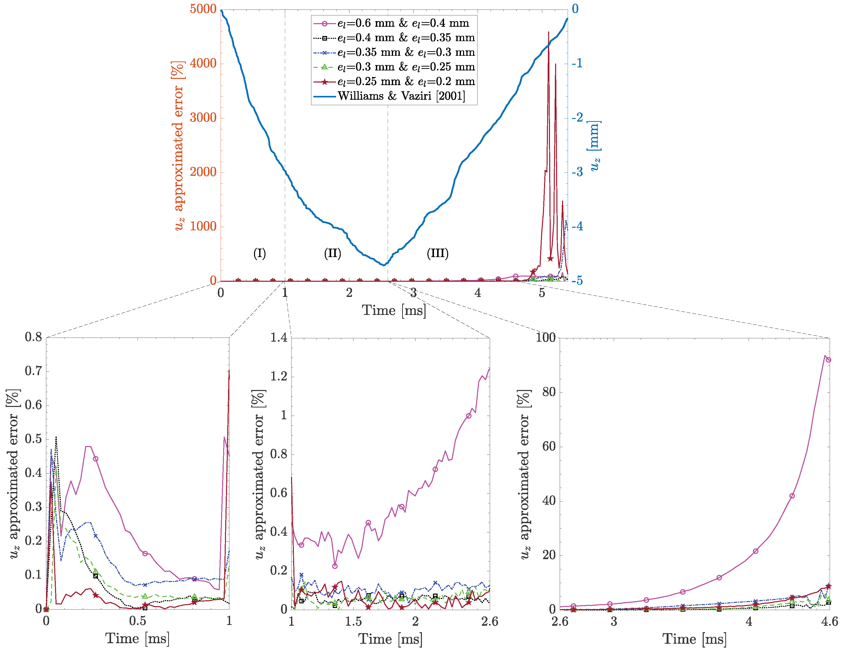
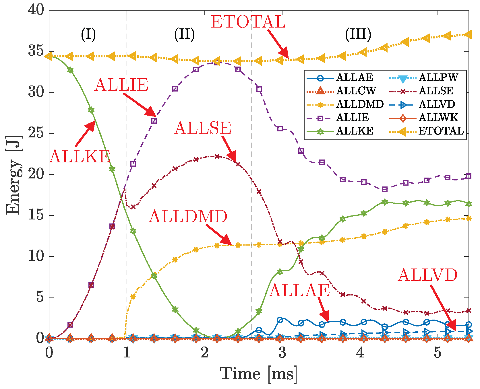
- Initial contact (0–1 ms)—Energy is conserved during this stage, as the total energy (ETOTAL) remains constant. During this stage, the kinetic energy (ALLKE) is converted to internal energy (ALLIE), which, due to the absence of damage, almost entirely consists of elastic strain energy (ALLSE). Contributions from other energy dissipation mechanisms, including work conducted by the external forces (ALLWK), contact penalties (ALLPW), constraint penalties (ALLCW), artificial energy (ALLAE), and viscous dissipated energy (ALLVD), are negligible.
- II.
- Damage initiation and evolution (1–2.6 ms)—The damage initiates at the beginning of this stage, where the difference between ALLIE and ALLSE becomes evident. This is captured by the increasing dissipated damage energy (ALLDMD), which gradually evolves and stabilizes between 2 and 2.6 ms. Despite the presence of damage, the total energy remains almost constant, indicating conservation of energy and a stable solution.
- III.
- Damage evolution and numerical instability (2.6–5.4 ms)—This stage is characterized by notable damage evolution and numerical instabilities due to severe element deformation. The oscillatory behavior of ALLAE indicates the activation of the hourglass control algorithm, which controls the hourglass mode. Additionally, the increase in ALLVD shows continuous added damping to the solver, helping maintain solution stability. The pronounced oscillations in ALLKE, ALLIE, and ALLSE, along with the gradual increase in ETOTAL—due to the cumulative effect of ALLAE and ALLVD—indicate numerical instabilities and the absence of energy conservation during this stage.
3.1.3. Stress Mesh Convergence: Number of Section Points
3.2. Mesh Convergence Study: Summary
| Case Study | [mm] | Section Points | ALLAE /ALLIE * [%] | ALLVD /ALLIE * [%] |
|---|---|---|---|---|
| #1 | 0.25 | 9 | 4.51 | 1.62 |
| #2 | 0.25 | 5 | 5.79 | 7.00 |
| #3 | 0.30 | 5 | 2.21 | 8.15 |
| #4 | 0.25 | 9 | 0.85 | 2.00 |
| #5 | 0.35 | 3 | 0.56 | 0.03 |
3.3. Effect of Projectile Modeling Technique on Contact Force Response of Conventional Shell Elements
3.4. Effect of Hourglass Control on Artificial Strain Energy of Conventional Shell Elements
3.5. Accuracy of Conventional Shell Elements in LVI Modeling of Thick Composite Laminates
4. Conclusions
- Mesh convergence study: A systematic mesh convergence study for CSEs, based on contact force, displacement, and stress, is proposed. The robustness of the proposed method is assessed against five experimental case studies. Contact force and displacement converge rapidly with relatively larger in-plane element sizes, e.g., 0.4 mm, with an approximated error below 10% during damage initiation and evolution. Stress convergence, however, is more demanding and requires convergence for both in-plane element size and number of section points. Stress convergence requires smaller in-plane element sizes, e.g., 0.25 mm, and up to nine section points through the thickness to ensure solution accuracy. Furthermore, stress convergence is particularly challenging during the damage initiation and evolution, although smaller in-plane element sizes and additional numbers of section points reduce the approximated error. Additionally, it is essential to monitor the ratio of the artificial strain energy to total internal energy and the ratio of viscous dissipated energy to internal energy—as solution accuracy metrics—below a certain limit (e.g., ≤10% in this paper) to ensure the solution is stable and physically reliable.
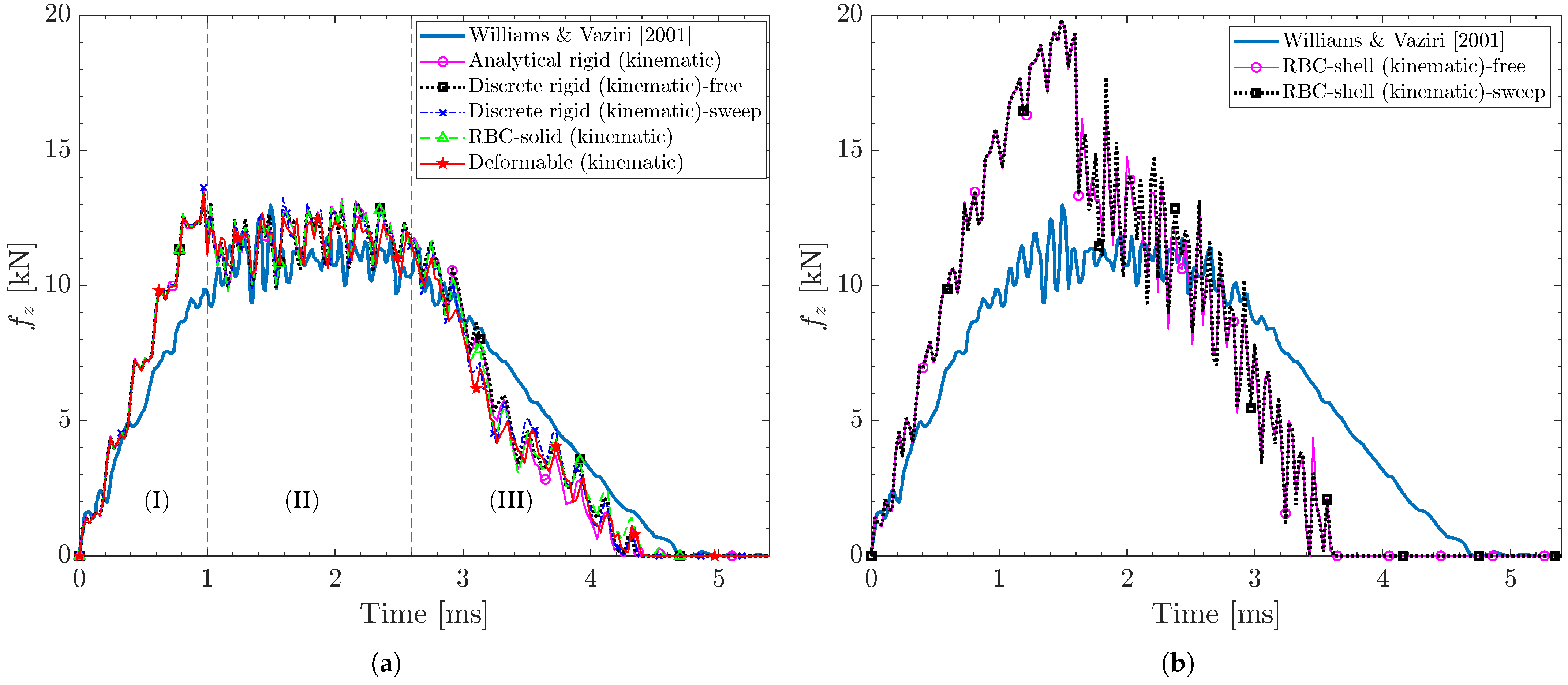
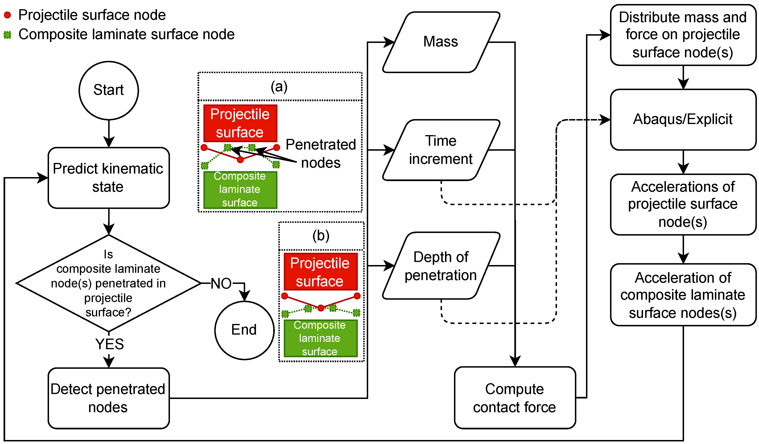
- Effect of projectile modeling technique on contact force response: Four projectile modeling techniques with different geometries and mesh control are evaluated: analytical rigid, discrete rigid—with free and sweep mesh controls—rigid body constraints (RBC) with solid geometry, RBC with shell geometry—with free and sweep mesh controls—and deformable projectiles. The contact force response is assessed through various contact constraint algorithms/interactions, including kinematic, penalty, and general contact (which enforces the penalty algorithm). The deformable projectile, using either the kinematic or penalty contact algorithm, remains the most accurate projectile modeling technique for LVI modeling of composite laminates. The penalty contact algorithm exhibits incompatibility with all rigid projectiles, potentially due to the stiffness mismatch between the projectile and the composite laminate. This mismatch affects the computation of the penalty coefficient used to prevent the penetration of the projectile into the composite laminate, resulting in the termination of the analysis. General contact demonstrates compatibility with all projectiles and accurately predicts the contact force response. However, energy history plots reveal that the total energy is not conserved throughout the analysis, particularly during damage initiation and evolution, compromising the accuracy of the finite element analysis.
- Effect of the hourglass algorithm on artificial strain energy: The ratio of the artificial strain energy—the dissipated energy due to the hourglass mode—to internal energy is used as a metric to assess three hourglass control algorithms: relax stiffness, pure stiffness, and enhanced. The enhanced algorithm results in the lowest ratio, indicating its capability in controlling the hourglass mode of S4R elements with minimal artificial stiffness and providing a more physically accurate response during LVI.
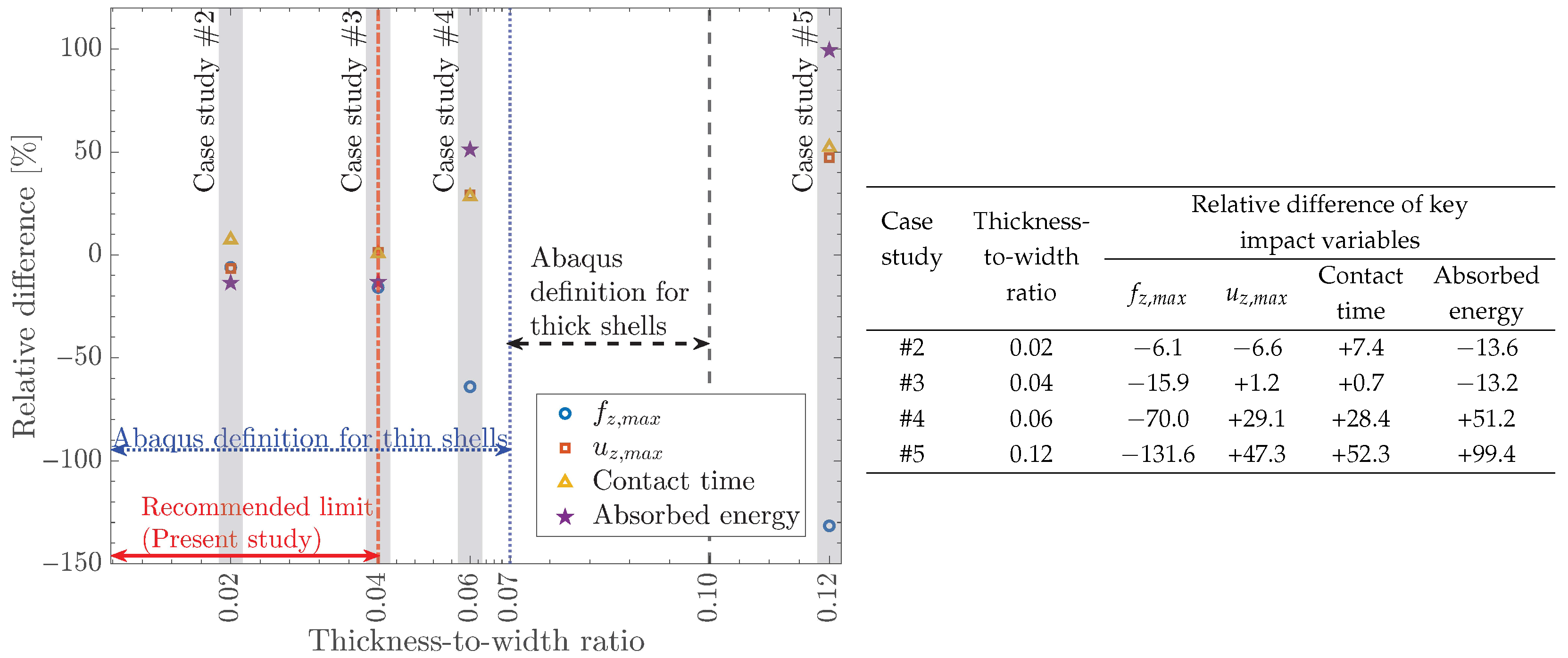
- Applicable thickness range of CSEs: The accuracy of S4R elements is assessed for four laminates with thickness-to-width ratios of 0.02, 0.04, 0.06, and 0.12 across four key impact variables: peak contact force and displacement, contact time, and absorbed energy. Results indicate that S4R elements can predict these impact variables with an absolute relative error of less than 16% for thickness-to-width ratios of less than 0.04. Beyond 0.04, S4R elements exhibit stiff behavior, overpredicting the contact force and underpredicting the displacement, contact time, and absorbed energy.
- Incorporate an interlaminar damage model: Future studies could include a more comprehensive damage model to account for interlaminar damage, i.e., delamination. Furthermore, this damage model can be used to assess the capability of CSEs in detecting delamination size—a critical post-impact metric. Additionally, the inclusion of interlaminar damage may enhance the ability of S4R elements to detect thickness variations during contact, leading to more accurate stress predictions during damage initiation and evolution.
- Parametric study on impact energy and velocity: Future studies could involve varying impact energies and velocities to assess the accuracy of CSE. This will help establish an envelope within which CSEs can be used for LVI modeling of composite laminates.
- Sub-component and component assessment: This paper is limited to coupon-level analyses. Extending the scope of this paper to sub-components, such as curved panels and stiffened skin, would enable an evaluation of how complex geometries and real-world boundary conditions affect the accuracy of CSEs.
Author Contributions
Funding
Data Availability Statement
Acknowledgments
Conflicts of Interest
Abbreviations
| BVID | Barely visible impact damage |
| CDM | Continuum damage model |
| CSE | Conventional shell element |
| DOF | Degrees of freedom |
| EAM | Energy absorption mechanism |
| FE | Finite element |
| FEA | Finite element analysis |
| FEM | Finite element method |
| FSDT | First-order shear deformation theory |
| LVI | Low-velocity impact |
| RBC | Rigid body constraint |
| RP | Reference point |
Appendix A. Definitions
Appendix B. Constitutive Damage Models of Composite Laminates
Appendix C. Material Properties and Impact Parameters
| Property | Symbol | Value | Unit | Reference |
|---|---|---|---|---|
| Density | 1550 | [109] | ||
| Longitudinal Young’s modulus | 152.4 | GPa | [74] | |
| Transverse Young’s modulus † | 9.2 | GPa | [74] | |
| In-plane shear modulus | 4.3 | GPa | [74] | |
| Out-of-plane shear modulus | 3.0 | GPa | - | |
| In-plane Poisson’s ratio | 0.35 | - | [74] | |
| Out-of-plane Poisson’s ratio | 0.53 | - | [110] | |
| Longitudinal tensile strength | 2089 | MPa | [74] | |
| Longitudinal compressive strength | 1482 | MPa | [74] | |
| Transverse tensile strength | 79 | MPa | [74] | |
| Transverse compressive strength | 231 | MPa | [74] | |
| Longitudinal shear strength | 133 | MPa | [74] | |
| Transverse shear strength * | 133 | MPa | - | |
| Longitudinal tensile fracture energy | 133 | [111] | ||
| Longitudinal compressive fracture energy | 40 | [111] | ||
| Transverse tensile fracture energy | 0.5 | [111] | ||
| Transverse compressive fracture energy | 1.6 | [111] | ||
| Dimension (thickness × length × width) | [74] |
| Property | Symbol | Value | Unit |
|---|---|---|---|
| Density | 1770 | ||
| Longitudinal Young’s modulus | 140 | GPa | |
| Transverse Young’s modulus | 8.6 | GPa | |
| In-plane shear modulus | 4.2 | GPa | |
| Out-of-plane shear modulus † | 3.3 | GPa | |
| In-plane Poisson’s ratio | 0.3 | - | |
| Out-of-plane Poisson’s ratio * | 0.3 | - | |
| Longitudinal tensile strength | 2160 | MPa | |
| Longitudinal compressive strength | 1236 | MPa | |
| Transverse tensile strength | 67 | MPa | |
| Transverse compressive strength * | 67 | MPa | |
| Longitudinal shear strength | 70 | MPa | |
| Transverse shear strength * | 70 | MPa | |
| Longitudinal tensile fracture energy | 120 | ||
| Longitudinal compressive fracture energy | 30 | ||
| Transverse tensile fracture energy | 0.385 | ||
| Transverse compressive fracture energy | 1.5 | ||
| Dimension (length × width) |
| Property | Symbol | Value | Unit |
|---|---|---|---|
| Density | 1600 | ||
| Longitudinal Young’s modulus | 149.5 | GPa | |
| Transverse Young’s modulus | 8.43 | GPa | |
| In-plane shear modulus | 4.2 | GPa | |
| Out-of-plane shear modulus | 2.52 | GPa | |
| In-plane Poisson’s ratio | 0.3 | - | |
| Out-of-plane Poisson’s ratio | 0.45 | - | |
| Longitudinal tensile strength | 2143 | MPa | |
| Longitudinal compressive strength | 1034 | MPa | |
| Transverse tensile strength | 75 | MPa | |
| Transverse compressive strength | 250 | MPa | |
| Longitudinal shear strength | 108 | MPa | |
| Transverse shear strength | 95 | MPa | |
| Longitudinal tensile fracture energy | 30.72 | ||
| Longitudinal compressive fracture energy | 7.15 | ||
| Transverse tensile fracture energy | 0.667 | ||
| Transverse compressive fracture energy | 7.41 | ||
| Dimension (thickness × length × width) |
References
- Daniel, I.; Ishai, O. Engineering Mechanics of Composite Materials, 2nd ed.; Oxford University Press: Oxford, UK, 2006. [Google Scholar]
- Bibo, G.A.; Hogg, P.J.; Backhouse, R.; Mills, A. Carbon-fibre non-crimp fabric laminates for cost-effective damage-tolerant structures. Compos. Sci. Technol. 1998, 58, 129–143. [Google Scholar] [CrossRef]
- Shyr, T.W.; Pan, Y.H. Impact resistance and damage characteristics of composite laminates. Compos. Struct. 2003, 62, 193–203. [Google Scholar] [CrossRef]
- Kazemian, M.; Cherniaev, A. Prediction of Damage in Non-Crimp Fabric Composites Subjected to Transverse Crushing: A Comparison of Two Constitutive Models. J. Compos. Sci. 2022, 6, 224. [Google Scholar] [CrossRef]
- Zhang, N.; Zhou, G.; Guo, X.; Xuan, S.; Wei, D.; Wang, X.; Cai, D. High-velocity impact damage and compression after impact behavior of carbon fiber composite laminates: Experimental study. Int. J. Impact Eng. 2023, 181, 104749. [Google Scholar] [CrossRef]
- Pascoe, J.A. Slow-growth damage tolerance for fatigue after impact in FRP composites: Why current research won’t get us there. Theor. Appl. Fract. Mech. 2021, 116, 103127. [Google Scholar] [CrossRef]
- Davies, G.A.; Olsson, R. Impact on composite structures. Aeronaut. J. 2004, 108, 541–563. [Google Scholar] [CrossRef]
- Verma, A.S.; Yan, J.; Hu, W.; Jiang, Z.; Shi, W.; Teuwen, J.J. A review of impact loads on composite wind turbine blades: Impact threats and classification. Renew. Sustain. Energy Rev. 2023, 178, 113261. [Google Scholar] [CrossRef]
- Hart, K.R.; Chia, P.X.; Sheridan, L.E.; Wetzel, E.D.; Sottos, N.R.; White, S.R. Comparison of Compression-After-Impact and Flexure-After-Impact protocols for 2D and 3D woven fiber-reinforced composites. Compos. Part A Appl. Sci. Manuf. 2017, 101, 471–479. [Google Scholar] [CrossRef]
- Liu, P.F.; Liao, B.B.; Jia, L.Y.; Peng, X.Q. Finite element analysis of dynamic progressive failure of carbon fiber composite laminates under low velocity impact. Compos. Struct. 2016, 149, 408–422. [Google Scholar] [CrossRef]
- Zhou, J.; Wen, P.; Wang, S. Finite element analysis of a modified progressive damage model for composite laminates under low-velocity impact. Compos. Struct. 2019, 225, 111113. [Google Scholar] [CrossRef]
- Zou, J.; Lei, Z.; Bai, R.; Liu, D.; Liu, H.; Huang, X.; Yan, C. Damage evolution and failure mechanism of asymmetric composite laminates under low-velocity impact and compression after impact. Thin-Walled Struct. 2023, 182, 110177. [Google Scholar] [CrossRef]
- Huang, L.; Tao, Y.; Sun, J.; Zhang, D.; Zhao, J. Assessment of numerical modeling approaches for thin composite laminates under low-velocity impact. Thin-Walled Struct. 2023, 191, 111053. [Google Scholar] [CrossRef]
- Ni, K.; Chen, Q.; Wen, J.; Cai, Y.; Zhu, Z.; Li, X. Low-velocity impact and post-impact compression properties of carbon/glass hybrid yacht composite materials. Ocean Eng. 2024, 292, 116448. [Google Scholar] [CrossRef]
- Cantwell, W.J.; Morton, J. The impact resistance of composite materials—A review. Composites 1991, 22, 347–362. [Google Scholar] [CrossRef]
- Gemi, L. Investigation of the effect of stacking sequence on low velocity impact response and damage formation in hybrid composite pipes under internal pressure. A comparative study. Compos. Part B Eng. 2018, 153, 217–232. [Google Scholar] [CrossRef]
- Barouni, A.K.; Dhakal, H.N. Damage investigation and assessment due to low-velocity impact on flax/glass hybrid composite plates. Compos. Struct. 2019, 226, 111224. [Google Scholar] [CrossRef]
- Bakhori, S.N.M.; Hassan, M.Z.; Bakhori, N.M.; Jamaludin, K.R.; Ramlie, F.; Daud, M.Y.M.; Aziz, S.A. Physical, Mechanical and Perforation Resistance of Natural-Synthetic Fiber Interply Laminate Hybrid Composites. Polymers 2022, 14, 1322. [Google Scholar] [CrossRef]
- Shah, S.Z.; Karuppanan, S.; Megat-Yusoff, P.S.; Sajid, Z. Impact resistance and damage tolerance of fiber reinforced composites: A review. Compos. Struct. 2019, 217, 100–121. [Google Scholar] [CrossRef]
- Singh, K.K.; Shinde, M. Impact Behavior of Fibre Reinforced Laminates; Springer: Singapore, 2022. [Google Scholar] [CrossRef]
- Greenhalgh, E.S. The influence of fibre architecture in the failure of polymer composites. In Failure Analysis and Fractography of Polymer Composites; Woodhead Publishing Limited: London, UK, 2009; pp. 279–355. [Google Scholar] [CrossRef]
- Loendersloot, R. Permeability of non-crimp fabric preforms. In Non-Crimp Fabric Composites; Woodhead Publishing Limited: London, UK, 2011; pp. 166–215. [Google Scholar] [CrossRef]
- Wan, L.; Ismail, Y.; Sheng, Y.; Ye, J.; Yang, D. A review on micromechanical modelling of progressive failure in unidirectional fibre-reinforced composites. Compos. Part C Open Access 2023, 10, 100348. [Google Scholar] [CrossRef]
- Cheryala, S.B.; Yerramalli, C.S. The role of fiber distribution on the in-situ resin behavior in the hybrid polymer composites. Mech. Mater. 2022, 173, 104446. [Google Scholar] [CrossRef]
- Reddy, Y.S.; Moorthy, C.M.; Reddy, J.N. Non-linear progressive failure analysis of laminated composite plates. Int. J. Non-Linear Mech. 1995, 30, 629–649. [Google Scholar] [CrossRef]
- Kim, Y.; Davalos, J.F.; Barbero, E.J. Progressive Failure Analysis of Laminated Composite Beams. J. Compos. Mater. 1996, 30, 536–560. [Google Scholar] [CrossRef]
- Mohammadi, B.; Hosseini-Toudeshky, H.; Sadr-Lahidjani, M.H. Progressive damage analyses of angle-ply laminates exhibiting free edge effects using continuum damage mechanics with layer-wise finite element method. Fatigue Fract. Eng. Mater. Struct. 2008, 31, 549–568. [Google Scholar] [CrossRef]
- Borkowski, L.B.; Kumar, R.S.; Palliyaguru, U.R. Coupled Analysis of Low-Velocity Impact Damage and Compression after Impact Strength of Composite Laminates. J. Aerosp. Eng. 2021, 34, 04021051. [Google Scholar] [CrossRef]
- Carrera, E.; Elishakoff, I.; Petrolo, M. Who needs refined structural theories? Compos. Struct. 2021, 264, 113671. [Google Scholar] [CrossRef]
- Khalili, S.M.; Soroush, M.; Davar, A.; Rahmani, O. Finite element modeling of low-velocity impact on laminated composite plates and cylindrical shells. Compos. Struct. 2011, 93, 1363–1375. [Google Scholar] [CrossRef]
- Bogenfeld, R.; Kreikemeier, J.; Wille, T. Review and benchmark study on the analysis of low-velocity impact on composite laminates. Eng. Fail. Anal. 2018, 86, 72–99. [Google Scholar] [CrossRef]
- González, E.V.; Maimí, P.; Martín-Santos, E.; Soto, A.; Cruz, P.; de la Escalera, F.M.; de Aja, J.R.S. Simulating drop-weight impact and compression after impact tests on composite laminates using conventional shell finite elements. Int. J. Solids Struct. 2018, 144–145, 230–247. [Google Scholar] [CrossRef]
- Schwab, M.; Todt, M.; Wolfahrt, M.; Pettermann, H.E. Failure mechanism based modelling of impact on fabric reinforced composite laminates based on shell elements. Compos. Sci. Technol. 2016, 128, 131–137. [Google Scholar] [CrossRef]
- Verma, A.S.; Vedvik, N.P.; Haselbach, P.U.; Gao, Z.; Jiang, Z. Comparison of numerical modelling techniques for impact investigation on a wind turbine blade. Compos. Struct. 2019, 209, 856–878. [Google Scholar] [CrossRef]
- Verma, A.S.; Jiang, Z.; Vedvik, N.P.; Gao, Z.; Ren, Z. Impact assessment of a wind turbine blade root during an offshore mating process. Eng. Struct. 2019, 180, 205–222. [Google Scholar] [CrossRef]
- Tessitore, N.; Riccio, A. A novel FEM model for biaxial non-crimp fabric composite materials under tension. Comput. Struct. 2006, 84, 1200–1207. [Google Scholar] [CrossRef]
- Tserpes, K.I.; Labeas, G.N. Mesomechanical analysis of non-crimp fabric composite structural parts. Compos. Struct. 2009, 87, 358–369. [Google Scholar] [CrossRef]
- Alabbad, M.; Vel, S.S.; Lopez-Anido, R.A. Computational model for predicting the low-velocity impact resistance and tolerance of composite laminates. Compos. Part B Eng. 2022, 244, 110187. [Google Scholar] [CrossRef]
- Raju, K.; Tay, T.E.; Tan, V.B.C. A review of the FE2 method for composites. Multiscale Multidiscip. Model. Exp. Des. 2021, 4, 1–24. [Google Scholar] [CrossRef]
- Li, S.; Sitnikova, E. Applications to textile composites. In Representative Volume Elements and Unit Cells; Woodhead Publishing: London, UK, 2020; pp. 371–415. [Google Scholar] [CrossRef]
- Bouvet, C.; Castanié, B.; Bizeul, M.; Barrau, J.J. Low velocity impact modelling in laminate composite panels with discrete interface elements. Int. J. Solids Struct. 2009, 46, 2809–2821. [Google Scholar] [CrossRef]
- Bouvet, C.; Rivallant, S.; Barrau, J.J. Low velocity impact modeling in composite laminates capturing permanent indentation. Compos. Sci. Technol. 2012, 72, 1977–1988. [Google Scholar] [CrossRef]
- Rivallant, S.; Bouvet, C.; Hongkarnjanakul, N. Failure analysis of CFRP laminates subjected to compression after impact: FE simulation using discrete interface elements. Compos. Part A Appl. Sci. Manuf. 2013, 55, 83–93. [Google Scholar] [CrossRef]
- Dubary, N.; Bouvet, C.; Rivallant, S.; Ratsifandrihana, L. Damage tolerance of an impacted composite laminate. Compos. Struct. 2018, 206, 261–271. [Google Scholar] [CrossRef]
- Trellu, A.; Bouvet, C.; Rivallant, S.; Ratsifandrihana, L. A new interface element connecting 3D finite elements with non-coincident nodes to simulate delamination in composite laminates. Compos. Struct. 2020, 252, 112694. [Google Scholar] [CrossRef]
- Shabani, P.; Li, L.; Laliberte, J.; Qi, G.; Rapking, D.; Mollenhauer, D. High-fidelity simulation of low-velocity impact damage in fiber-reinforced composite laminates using integrated discrete and continuum damage models. Compos. Struct. 2023, 313, 116910. [Google Scholar] [CrossRef]
- Sellitto, A.; Saputo, S.; Caprio, F.D.; Riccio, A.; Russo, A.; Acanfora, V. Numerical–Experimental Correlation of Impact-Induced Damages in CFRP Laminates. Appl. Sci. 2019, 9, 2372. [Google Scholar] [CrossRef]
- Ouyang, T.; Bao, R.; Sun, W.; Guan, Z.; Tan, R. A fast and efficient numerical prediction of compression after impact (CAI) strength of composite laminates and structures. Thin-Walled Struct. 2020, 148, 106588. [Google Scholar] [CrossRef]
- Chen, W.Q.; Lee, K.Y. Three-dimensional exact analysis of angle-ply laminates in cylindrical bending with interfacial damage via state-space method. Compos. Struct. 2004, 64, 275–283. [Google Scholar] [CrossRef]
- Chen, W.Q.; Cai, J.B.; Ye, G.R. Exact Solutions of Cross-Ply Laminates with Bonding Imperfections. AIAA J. 2012, 41, 2244–2250. [Google Scholar] [CrossRef]
- Lopes, C.S.; Sádaba, S.; González, C.; Llorca, J.; Camanho, P.P. Physically-sound simulation of low-velocity impact on fiber reinforced laminates. Int. J. Impact Eng. 2016, 92, 3–17. [Google Scholar] [CrossRef]
- Falcó, O.; Ávila, R.L.; Tijs, B.; Lopes, C.S. Modelling and simulation methodology for unidirectional composite laminates in a Virtual Test Lab framework. Compos. Struct. 2018, 190, 137–159. [Google Scholar] [CrossRef]
- Millen, S.L.; Ullah, Z.; Falzon, B.G. On the importance of finite element mesh alignment along the fibre direction for modelling damage in fibre-reinforced polymer composite laminates. Compos. Struct. 2021, 278, 114694. [Google Scholar] [CrossRef]
- Falcó, O.; Lopes, C.S.; Sommer, D.E.; Thomson, D.; Ávila, R.L.; Tijs, B.H. Experimental analysis and simulation of low-velocity impact damage of composite laminates. Compos. Struct. 2022, 287, 115278. [Google Scholar] [CrossRef]
- Rajaneesh, A.; Bruyneel, M. Low-velocity impact and compression after impact modeling of composites using modified mesoscale model. Compos. Struct. 2023, 311, 116821. [Google Scholar] [CrossRef]
- Leone, F.A.; Rose, C.A.; Jackson, W.C.; Seshadri, B.R. Low-Velocity Impact Analyses of Composite Panels Using Cohesive Zone Modeling and Continuum Damage Mechanics. In Proceedings of the AIAA SciTech Forum and Exposition, Orlando, FL, USA, 8–12 January 2024. [Google Scholar] [CrossRef]
- Systèmes, D. SIMULIA User Assistance 2021; Dassault Systèmes Simulia Corp: Waltham, MA, USA, 2021. [Google Scholar]
- Boudounit, H.; Tarfaoui, M.; Saifaoui, D.; Qureshi, Y. Parametric Study of Accidental Impacts on an Offshore Wind Turbine Composite Blade. J. Bio- Tribo-Corros. 2021, 7, 1–21. [Google Scholar] [CrossRef]
- Shabani, P.; Shabani, N. Fatigue life prediction of high-speed composite craft under slamming loads using progressive fatigue damage modeling technique. Eng. Fail. Anal. 2022, 131, 105818. [Google Scholar] [CrossRef]
- Stamoulis, K.; Georgantzinos, S.K.; Giannopoulos, G.I. Damage characteristics in laminated composite structures subjected to low-velocity impact. Int. J. Struct. Integr. 2020, 11, 670–685. [Google Scholar] [CrossRef]
- Kumar, K.; Surendran, S. Design and analysis of composite panel for impact loads in marine environment. Ships Offshore Struct. 2013, 8, 597–606. [Google Scholar] [CrossRef]
- Kumbasar, B.B.; Gider, B. The effects of mass scale and hourglass control for low velocity impact simulations on abaqus. In Proceedings of the AIAA Scitech 2021 Forum, Virtual, 11–15 & 19–21 January 2021; pp. 1–15. [Google Scholar] [CrossRef]
- Magomedov, I.A.; Sebaeva, Z.S. Comparative study of finite element analysis software packages. J. Physics Conf. Ser. 2020, 1515, 032073. [Google Scholar] [CrossRef]
- Maziz, A.; Tarfaoui, M.; Gemi, L.; Rechak, S.; Nachtane, M. A progressive damage model for pressurized filament-wound hybrid composite pipe under low-velocity impact. Compos. Struct. 2021, 276, 114520. [Google Scholar] [CrossRef]
- Hashin, Z.; Rotem, A. A Fatigue Failure Criterion for Fiber Reinforced Materials. J. Compos. Mater. 1973, 7, 448–464. [Google Scholar] [CrossRef]
- Hashin, Z. Failure Criteria for Unidirectional Fiber Composites. J. Appl. Mech. 1980, 47, 329–334. [Google Scholar] [CrossRef]
- Puck, A.; Schürmann, H. Failure analysis of FRP laminates by means of physically based phenomenological models. Compos. Sci. Technol. 2002, 62, 1633–1662. [Google Scholar] [CrossRef]
- Puck, A.; Kopp, J.; Knops, M. Guidelines for the determination of the parameters in Puck’s action plane strength criterion. Compos. Sci. Technol. 2002, 62, 371–378. [Google Scholar] [CrossRef]
- Davila, C.G.; Camanho, P.P. Failure Criteria for FRP Laminates in Plane Stress; Technical report; NASA: Washington, DC, USA, 2003. [Google Scholar]
- Pinho, S.T.; Darvizeh, R.; Robinson, P.; Schuecker, C.; Camanho, P.P. Material and structural response of polymer-matrix fibre-reinforced composites. J. Compos. Mater. 2012, 46, 2313–2341. [Google Scholar] [CrossRef]
- Kazemianfar, B.; Nami, M.R. Influence of oblique low velocity impact on damage behavior of 2D and 3D woven composites: Experimental and numerical methods. Thin-Walled Struct. 2021, 167, 108253. [Google Scholar] [CrossRef]
- Sun, J.; Huang, L.; Zhao, J. Oblique Low-Velocity Impact Response and Damage Behavior of Carbon-Epoxy Composite Laminates. Materials 2022, 15, 5256. [Google Scholar] [CrossRef] [PubMed]
- ASTM D7136/D7136M-15; Test Method for Measuring the Damage Resistance of a Fiber-Reinforced Polymer Matrix Composite to a Drop-Weight Impact Event. ASTM International: West Conshohocken, PA, USA, 2020; Volume 15.03. [CrossRef]
- Williams, K.V.; Vaziri, R. Application of a damage mechanics model for predicting the impact response of composite materials. Comput. Struct. 2001, 79, 997–1011. [Google Scholar] [CrossRef]
- Sachse, R.; Pickett, A.K.; Middendorf, P. Simulation of impact and residual strength of thick laminate composites. Compos. Part B Eng. 2020, 195, 108070. [Google Scholar] [CrossRef]
- Loganathan, T.M.; Sultan, M.T.; Gobalakrishnan, M.K.; Muthaiyah, G. Ballistic impact response of laminated hybrid composite materials. In Mechanical and Physical Testing of Biocomposites, Fibre-Reinforced Composites and Hybrid Composites; Woodhead Publishing: London, UK, 2019; pp. 171–191. [Google Scholar] [CrossRef]
- Phadnis, V.A.; Roy, A.; Silberschmidt, V.V. Dynamic damage in FRPs: From low to high velocity. In Dynamic Deformation, Damage and Fracture in Composite Materials and Structures, Second Edition; Woodhead Publishing: London, UK, 2023; pp. 165–193. [Google Scholar] [CrossRef]
- Chen, D.; Luo, Q.; Meng, M.; Sun, G. Low velocity impact behavior of interlayer hybrid composite laminates with carbon/glass/basalt fibres. Compos. Part B Eng. 2019, 176, 107191. [Google Scholar] [CrossRef]
- Subadra, S.P.; Griskevicius, P.; Yousef, S. Low velocity impact and pseudo-ductile behaviour of carbon/glass/epoxy and carbon/glass/PMMA hybrid composite laminates for aircraft application at service temperature. Polym. Test. 2020, 89, 106711. [Google Scholar] [CrossRef]
- Zhang, C.; Rao, Y.; Li, W. Low-velocity impact behavior of intralayer hybrid composites based on carbon and glass non-crimp fabric. Compos. Struct. 2020, 234, 111713. [Google Scholar] [CrossRef]
- Lyu, Q.; Wang, B.; Zhao, Z.; Guo, Z. Damage and failure analysis of hybrid laminates with different ply-stacking sequences under low-velocity impact and post-impact compression. Thin-Walled Struct. 2022, 180, 109743. [Google Scholar] [CrossRef]
- Matzenmiller, A.; Lubliner, J.; Taylor, R.L. A constitutive model for anisotropic damage in fiber-composites. Mech. Mater. 1995, 20, 125–152. [Google Scholar] [CrossRef]
- Boulbes, R.J. Troubleshooting Finite-Element Modeling with Abaqus, 1st ed.; Springer International Publishing: Cham, Switzerland, 2020. [Google Scholar] [CrossRef]
- Tsai, S.W.; Hahn, H.T. Introduction to Composite Materials, 1st ed.; CRC Press: Boca Raton, FL, USA, 1980. [Google Scholar]
- Zhang, J.; Zhang, X. An efficient approach for predicting low-velocity impact force and damage in composite laminates. Compos. Struct. 2015, 130, 85–94. [Google Scholar] [CrossRef]
- Chapra, S.C. Applied Numerical Methods with MATLAB for Engineers and Scientists, 5th ed.; McGraw Hill LLC: Columbus, OH, USA, 2023. [Google Scholar]
- Silva, M.A.; Cismaşiu, C.; Chiorean, C.G. Numerical simulation of ballistic impact on composite laminates. Int. J. Impact Eng. 2005, 31, 289–306. [Google Scholar] [CrossRef]
- Cook, R.D.; Malkus, D.S.; Plesha, M.E.; Witt, R.J.W. Concept and Applications of Finite Element Analysis, 4th ed.; Wiley: Hoboken, NJ, USA, 2001; p. 733. [Google Scholar]
- Belytschko, T.; Ong, J.S.J.; Liu, W.K.; Kennedy, J.M. Hourglass control in linear and nonlinear problems. Comput. Methods Appl. Mech. Eng. 1984, 43, 251–276. [Google Scholar] [CrossRef]
- Hoffmann, M.; Zimmermann, K.; Bautz, B.; Middendorf, P. A new specimen geometry to determine the through-thickness tensile strength of composite laminates. Compos. Part B Eng. 2015, 77, 145–152. [Google Scholar] [CrossRef]
- Hidalgo, J.P.; Pironi, P.; Hadden, R.M.; Welch, S. A framework for evaluating the thermal behaviour of carbon fibre composite materials. In Proceedings of the 2nd IAFSS European Symposium of Fire Safety Science, Nicosia, Cyprus, 16–18 June 2015; pp. 195–200. [Google Scholar]
- Zimmermann, K.; Zenkert, D.; Siemetzki, M. Testing and analysis of ultra thick composites. Compos. Part B Eng. 2010, 41, 326–336. [Google Scholar] [CrossRef]
- Nilsson, S.; Bredberg, A.; Asp, L.E. Effects of CFRP laminate thickness on bending after impact strength. Plast. Rubber Compos. 2009, 38, 61–66. [Google Scholar] [CrossRef]
- Nettles, A.T.; Hromisin, S.M. Normalization of Impact Energy by Laminate Thickness for Compression After Impact Testing; Technical Report; NASA: Washington, DC, USA, 2013. [Google Scholar]
- Damghani, M.; Saddler, J.; Sammon, E.; Atkinson, G.A.; Matthews, J.; Murphy, A. An experimental investigation of the impact response and Post-impact shear buckling behaviour of hybrid composite laminates. Compos. Struct. 2023, 305, 116506. [Google Scholar] [CrossRef]
- Roberts, E.M.; Justusson, B.P.; Schaefer, J.D.; Wanthal, S.P. Improved benchmarking of cohesive elements in abaqus standard for predicting disbond and delamination in composite structures. In Proceedings of the AIAA Scitech 2021 Forum, Virtual, 11–15 & 19–21 January 2021; pp. 1–19. [Google Scholar] [CrossRef]
- Reddy, J.N. Mechanics of Laminated Composite Plates and Shells: Theory and Analysis, Second Edition; CRC Press: Boca Raton, FL, USA, 2003. [Google Scholar] [CrossRef]
- Mallikarjuna; Kant, T. A critical review and some results of recently developed refined theories of fiber-reinforced laminated composites and sandwiches. Compos. Struct. 1993, 23, 293–312. [Google Scholar] [CrossRef]
- Teotia, M.; Soni, R.K. Applications of finite element modelling in failure analysis of laminated glass composites: A review. Eng. Fail. Anal. 2018, 94, 412–437. [Google Scholar] [CrossRef]
- Ambartsumian, S.A. Nontraditional theories of shells and plates. Appl. Mech. Rev. 2002, 55, R35–R44. [Google Scholar] [CrossRef]
- Abrate, S. Impact on Composite Structures; Cambridge University Press: Cambridge, UK, 1998. [Google Scholar] [CrossRef]
- Abdullah, S.I.B.S. Low Velocity Impact Testing on Laminated Composites. In Impact Studies of Composite Materials; Springer: Singapore, 2021; Chapter 1; pp. 1–17. [Google Scholar] [CrossRef]
- Reddy, J.N. A Refined Shear Deformation Theory for the Analysis of Laminated Plates; Technical Report; NASA: Washington, DC, USA, 1986. [Google Scholar]
- Reis, P.N.; Sousa, P.; Ferreira, L.M.; Coelho, C.A. Multi-impact response of semicylindrical composite laminated shells with different thicknesses. Compos. Struct. 2023, 310, 116771. [Google Scholar] [CrossRef]
- Thorsson, S.I.; Waas, A.M.; Rassaian, M. Low-velocity impact predictions of composite laminates using a continuum shell based modeling approach part A: Impact study. Int. J. Solids Struct. 2018, 155, 185–200. [Google Scholar] [CrossRef]
- Park, R.; Jang, J. Impact behavior of aramid fiber/glass fiber hybrid composites: The effect of stacking sequence. Polym. Compos. 2001, 22, 80–89. [Google Scholar] [CrossRef]
- Lai, W.M. Introduction to Continuum Mechanics, 4th ed.; Elsevier: Burlington, MA, USA, 2010. [Google Scholar]
- Camanho, P.P.; Davila, C.G. Mixed-Mode Decohesion Finite Elements for the Simulation of Delamination in Composite Materials; NASA/TM-2002-211737; NASA: Washington, DC, USA, 2002; pp. 1–37. [Google Scholar]
- Ghosh, A.; Sinha, P.K. Initiation and propagation of damage in laminated composite shells due to low velocity impact. Int. J. Crashworthiness 2005, 10, 379–388. [Google Scholar] [CrossRef]
- Caprino, G.; Iaccarino, P.; Lamboglia, A. The effect of shear on the rigidity in three-point bending of unidirectional CFRP laminates made of T800H/3900-2. Compos. Struct. 2009, 88, 360–366. [Google Scholar] [CrossRef]
- Liu, H.; Liu, J.; Ding, Y.; Zhou, J.; Kong, X.; Blackman, B.R.; Kinloch, A.J.; Falzon, B.G.; Dear, J.P. Effects of Impactor Geometry on the Low-Velocity Impact Behaviour of Fibre-Reinforced Composites: An Experimental and Theoretical Investigation. Appl. Compos. Mater. 2020, 27, 533–553. [Google Scholar] [CrossRef]









| Level of Fidelity | FE Modeling Technique | Model Characteristic(s) | Advantage(s) | Disadvantage(s) | References |
|---|---|---|---|---|---|
| Low-fidelity | Layer-wise | Based on ad hoc assumptions from plate and shell theories | Efficient in capturing the overall response | Inefficient in providing detailed analysis of EAMs and accurate stress prediction compared to engineering models | [25,26,27,28,29] |
| Mid-fidelity | Conventional shell elements | - Represent laminate geometry using a surface - Use through-the-thickness section points for stress prediction | - Computationally inexpensive due to reduced DOF - Do not affect stable time increment in explicit solvers - Easy to integrate with solid and/or cohesive elements - Suitable for capturing global laminate behavior | - Insensitive to thickness variation - Exhibit overstiff behavior - Limited accuracy for thick laminates due to simplified formulation | [30,31,32,33,34,35] |
| High-fidelity | Multiscale | - Based on RVE * (to link microscale properties to macroscale model) - Uncoupled: microscale properties derived from RVE and applied to macroscale model - Coupled: and Direct | Effective in capturing details of EAMs | - Computationally expensive - Complex in scale transition relations - RVE depends on boundary conditions and geometry, being further complicated by irregularities of the textile | [36,37,38,39,40] |
| Discrete ply method | - Use solid elements to model composite layers - Use cohesive elements/cohesive surface between and within layers | Model matrix cracking and delamination interaction | - Computationally expensive - Requires very fine mesh - Predicts damage at predefined locations - Constraints on solid element size and mesh coincidence - Restricted to a limited ply orientation - Limited handling of nonuniform stress and complex load path | [41,42,43,44,45,46] | |
| Engineering models | - Approximate lamina properties as effective elastic constants - Neglect mesoscale heterogeneity - Use solid/shell elements to model layers - Use cohesive elements/cohesive between layers | - Requires less material input - Computationally efficient | - Limited to macroscale analysis - No interaction between various EAMs | [32,33,47] | |
| Combined FEM–image recognition | Use C-scan result to introduce damage in FEM model | Computationally efficient | - In the development phase - Lacks validation against various stacking sequences | [12,48] | |
| Stress-state | More accurate stress and displacement fields than layer-wise | Suitable for nonlinear and transient analysis | Reduced efficiency in three-dimensional models with damage and a fine mesh (state variables increase with the increasing system of equations) | [49,50] | |
| Fiber-aligned mesh | Elements align with fiber direction per layer | Suitable for matrix cracking patterns and their interactions with delamination | - Computationally expensive - Complex mesh generation - Limited to specific fiber orientation - Requires cohesive surface to manage layer orientation | [51,52,53,54,55,56] |
| Row | Projectile Modeling Technique | Geometry | Element Type | Mesh Control | Deformation | User Control |
|---|---|---|---|---|---|---|
| 1 | Analytical rigid | Shell + RP * | - | - | Rigid | Low |
| 2 | Discreet rigid | Shell + RP | R3D4 | Free/Sweep | Rigid | High |
| 3a | RBC-solid | Solid + RP | C3D8R | Free | Rigid | High |
| 3b | RBC-shell | Shell + RP | S4R | Free/Sweep | Rigid | High |
| 4 | Deformable | Solid | C3D8R | Free | Deformable | High |
| Energy Variable | Definition |
|---|---|
| ALLAE | Artificial strain energy due to hourglass |
| ALLDMD | Dissipated energy through damage |
| ALLSE | Elastic strain energy |
| ALLKE | Kinetic energy |
| ALLVD | Viscous dissipated energy due to numerical damping |
| ALLWK | Work by external forces |
| ALLPW | Work by contact penalties |
| ALLCW | Work by constraint penalties |
| ALLIE | Total internal energy (in this study, ALLIE = ALLSE + ALLAE + ALLDMD) |
| ETOTAL | Total energy (in this study, ETOTAL = ALLIE + ALLVD + ALLKE − ALLWK − ALLPW − ALLCW) |
| Projectile Modeling Technique | Mesh Strategy | Contact Algorithm/Interaction | ||
|---|---|---|---|---|
| Kinematics | Penalty | General Contact (Penalty) | ||
| Analytical rigid | - | ✓ | × | ✓ * |
| Discrete rigid | Free | ✓ | × | ✓ * |
| Discrete rigid | Sweep | ✓ | × | ✓ * |
| RBC-solid | - | ✓ | × | ✓ * |
| RBC-shell | Free | × | × | ✓ * |
| RBC-shell | Sweep | × | × | ✓ * |
| Deformable | - | ✓ | ✓ | ✓ * |
| Hourglass Algorithm | Relax Stiffness * | Stiffness | Enhanced |
|---|---|---|---|
| ALLAE/ALLIE [%] | 4.51 | 4.32 | 4.23 |
Disclaimer/Publisher’s Note: The statements, opinions and data contained in all publications are solely those of the individual author(s) and contributor(s) and not of MDPI and/or the editor(s). MDPI and/or the editor(s) disclaim responsibility for any injury to people or property resulting from any ideas, methods, instructions or products referred to in the content. |
© 2025 by the authors. Licensee MDPI, Basel, Switzerland. This article is an open access article distributed under the terms and conditions of the Creative Commons Attribution (CC BY) license (https://creativecommons.org/licenses/by/4.0/).
Share and Cite
Baharvand, A.; Verma, A.S. Low-Velocity Impact Modeling of Fiber-Reinforced Composites Using Shell Elements: A Benchmark Study. J. Compos. Sci. 2025, 9, 587. https://doi.org/10.3390/jcs9110587
Baharvand A, Verma AS. Low-Velocity Impact Modeling of Fiber-Reinforced Composites Using Shell Elements: A Benchmark Study. Journal of Composites Science. 2025; 9(11):587. https://doi.org/10.3390/jcs9110587
Chicago/Turabian StyleBaharvand, Amir, and Amrit Shankar Verma. 2025. "Low-Velocity Impact Modeling of Fiber-Reinforced Composites Using Shell Elements: A Benchmark Study" Journal of Composites Science 9, no. 11: 587. https://doi.org/10.3390/jcs9110587
APA StyleBaharvand, A., & Verma, A. S. (2025). Low-Velocity Impact Modeling of Fiber-Reinforced Composites Using Shell Elements: A Benchmark Study. Journal of Composites Science, 9(11), 587. https://doi.org/10.3390/jcs9110587


