Article

Cyclic Loading Response and Failure Mechanism of Composite Auxetic Perforated Buckling-Restrained Braces: A Comparative Study of Q235B and LY160 Steel

1
School of Architecture and Planning, Yunnan University, Kunming 650000, China
2
College of Architecture and Civil Engineering, Kunming University, Kunming 650000, China
*
Author to whom correspondence should be addressed.
J. Compos. Sci. 2025, 9(11), 581; https://doi.org/10.3390/jcs9110581
Submission received: 23 September 2025 / Revised: 17 October 2025 / Accepted: 27 October 2025 / Published: 29 October 2025
(This article belongs to the Special Issue Metal Composites, Volume II)

Abstract

Auxetic materials and structures exhibit high energy absorption, vibration damping, and fracture toughness at the macroscopic level. Lightweight designs and perforated structures in buckling-restrained braces (BRBs) have garnered significant attention. However, existing auxetic cellular configurations remain relatively simplistic, with particularly limited options capable of synergizing with BRBs to achieve combined energy dissipation and seismic mitigation performance. This study introduces a novel composite auxetic cellular unit with a honeycomb structure of negative Poisson’s ratio and corresponding design method. The cellular unit is combined with a BRB to develop a new composite auxetic perforated BRB (NPR-BRB). Experimental and numerical simulation methods are used to investigate the effects of two core plate materials (Q235B and LY160), the reentrant angle, and the cross-sectional weakening rate of the composite honeycombs on the NPR-BRB’s performance under cyclic loading. In this study, four BRB specimens were fabricated, and the experimental results reveal that the fracture surface morphology (cup- and shell-shaped) depends on the deformation mechanism. One of the NPR-BRBs demonstrates stable hysteretic behavior, with an equivalent viscous damping ratio of 0.469 and a cumulative plastic strain of 219.7. Numerical simulations indicate that the LY160 BRB exhibits higher deformation capacity and energy dissipation, reducing stress concentration. The concavity angle has a negligible influence on performance. An increase in the cross-sectional weakening rate is correlated with a reduction in bearing capacity, hysteresis loop area, and compression–tension asymmetry, and an increase followed by a decrease in equivalent viscous damping ratio and cumulative plastic strain. The novel hybrid auxetic cellular units may enhance the energy dissipation performance of BRBs.

1. Introduction

Auxetic, also referred to as Metamaterials [1], such as Negative Poisson’s ratio (NPR) materials and structures [2,3], are engineered structures with unique mechanical properties. These materials were proposed by Evans in 1991 and have attracted substantial attention due to their distinctive auxetic behavior, which involves expansion in response to stretching. The term “auxetic” is derived from the Greek word for “growth” or “expansion,” emphasizing their unique property. Alderson and Grima [4,5] found that the NPR effect was scale-invariant and occurred at the microscopic material level and the macroscopic structural level. Thus, it is an intrinsic material property and a structural feature. Unlike traditional materials with positive Poisson’s ratios, NPR materials and structures demonstrate superior energy absorption [6,7,8,9], vibration isolation [10], fracture toughness [11], and a high shear modulus [12,13,14].
Poisson’s ratio, named after French scientist Siméon Denis Poisson (1787–1840), is a material’s lateral strain to longitudinal strain ratio under elastic loading. Most natural materials have positive Poisson’s ratios, expanding laterally when compressed and contracting when stretched. However, certain natural materials exhibit an NPR, such as pyrite crystals and cubic metallic structures [15]. Inspired by these materials, researchers have developed different NPR materials [16] and structures using structural optimization [17,18,19]. Lakes [20] synthesized the first artificial NPR material: a polyester-based polyurethane foam, marking the advent of synthetic NPR materials. Since then, NPR materials have received extensive scholarly attention [21,22,23], advancing the concept and design methodologies for these unique materials [24]. With in-depth research, NPR materials and structures have been applied in high-tech fields [25,26,27], such as biomedicine [28], aerospace [29], automotive [30], and defense [31]. As NPR technologies have matured, and their high energy absorption capabilities and broad tunable frequency gaps have gained recognition [32], interest has turned toward their potential in energy dissipation and seismic isolation in construction engineering. For example, research has been conducted on auxetic-shaped steel plate shear walls [33]. Auxetic-shaped were designed on steel plate shear walls, with experimental and numerical analyses demonstrating that the auxetic-shaped steel plate shear walls maintain stable energy dissipation capacity while achieving significant weight reduction in the structural system. High-performance concrete [34,35,36] with auxetic properties [37] has been obtained by winding fibers with different strengths and integrating them into concrete. Consequently, the incorporation of auxetic technology into construction engineering is imperative for improving seismic performance.
A buckling-restrained brace (BRB) is an integrated damping device combining a core element and a restraining element, as shown in Figure 1, an all-steel buckling-restrained brace is presented, illustrating both its structural schematic diagram and assembly drawing of components. The BRB design is based on elastic-plastic buckling and the hysteresis characteristics of the core. It prevents high-order out-of-plane buckling, increasing energy dissipation efficiency. Under cyclic loading, the BRB undergoes uniform yielding in tension and compression, avoiding local buckling [38]. This performance relies on the deformation capacity of the core plate’s energy-dissipative segment [39], making the core plate a central research focus.
In addition to commonly used materials like GB Q235B steel [40], alternatives, such as aluminum alloys [41], low-yield-point steels [42,43], and shape memory alloys [44] have been widely used to fabricate the core element [45]. These materials are selected to improve the BRB’s performance and adaptability. The low-yield-point steel demonstrates superior energy dissipation capacity as BRB core material compared to Q235 steel, exhibiting symmetrical, stable and fully developed hysteretic loops. This evidences the critical importance of low-yield steel’s high ductility and exceptional fatigue resistance for BRB applications. The core plates have various configurations, including cylindrical sections and BRBs composed of multiple core plates. Research on weakening and perforating the energy-dissipating segments of core plates has increased significantly in recent years. For instance, an all-steel fishbone-type BRB has been developed by weakening both sides of the core plate [46]. Another innovation, the all-steel perforated core BRB [47], reduces self-weight and facilitates post-earthquake inspection and maintenance.
The trend for BRBs is toward lightweight, high-energy-dissipation, and all-steel designs, with perforations in the core gaining popularity for performance enhancement. Concurrently, NPR materials and structures exhibit excellent energy dissipation and vibration-damping capacity. Combining perforated BRBs with NPR properties could synergize their strengths. In 2021, Zhang et al. [48] proposed a novel BRB with elliptical NPR cells in the core plate that exhibited higher energy dissipation than traditional perforated BRBs with a positive Poisson’s ratio. Subsequently, Zhu et al. [49] utilized peanut-shaped NPR cells in BRB core plate perforations, yielding more pronounced NPR behavior than elliptical openings. The results demonstrate that compared to conventional perforated BRBs, the peanut-shaped perforated core BRB exhibits superior energy dissipation capacity and more stable hysteretic behavior. Furthermore, the in-plane deformation of the auxetic perforation cells effectively delays out-of-plane buckling of the core plate, thereby enhancing the overall ductility of the BRB system. Additionally, Zhang et al. [50] developed a BRB with triply symmetric dumbbell-shaped cells for isotropic deformation, mitigating anisotropy in existing NPR-BRB designs. Basir et al. [51] employed finite element software to analyze concave hexagonal openings in BRBs, examining the effects of different perforation parameters on BRB performance. Previous studies have demonstrated that optimized auxetic cellular structures can enhance both the energy dissipation stability and capacity of auxetic perforated core BRBs, while simultaneously alleviating stress concentration issues. However, previous studies have only focused on the application of lattice combinations among a single type of cell, research on the design and optimization of auxetic cellular units remains limited. The development of novel auxetic cellular configurations may hold significant potential for improving the fatigue resistance and energy dissipation performance of NPR-perforated core BRBs. Therefore, building on previous research, this study proposes an innovative composite auxetic cellular unit design. This study proposes a novel composite metamaterial cell that combines a re-entrant hexagonal structure and a double-arrow auxiliary structure, integrating it into BRB core plates to create a new composite auxetic perforated BRB (NPR-BRB). This paper investigates the mechanical properties of the NPR-BRB under cyclic loading using comprehensive experimental and numerical analyses.
The paper first explains the design principles and operating mechanisms of the NPR cellular unit, describes the detailed test procedures, and provides an in-depth discussion of experimental results. Numerical simulations are conducted to assess the impacts of the core plate material, cellular units’ concavity angle, and cross-sectional weakening rate on the NPR-BRB performance. This study’s limitations are discussed, and future research directions are recommended, providing references and implications for subsequent investigations.

2. Design of Composite Auxetic Cellular Units

2.1. Deformation Mechanism

Previous studies have described and analyzed various two-dimensional structures with NPRs, including chiral structures [52,53], reentrant grids [54], and concave honeycomb structures [55]. The two-dimensional concave hexagons and double-arrow auxiliary structure are classic configurations that have received extensive attention. The deformation mechanism of the double-arrow auxiliary structure is illustrated in Figure 2a. When this structure is subjected to a compressive force, the internal angle θ1 decreases, causing the inclined struts to rotate and the structure to undergo biaxial contraction in the plane, i.e., an NPR effect. Similarly, when horizontal pressure is applied to a two-dimensional concave hexagonal honeycomb structure, its longitudinal struts retract. This behavior is attributed to the action of the inclined struts under compression: the concave angle of a single hexagon increases, with the inclined struts rotating around the intersection with the vertical struts, resulting in an NPR of the entire structure, as depicted in Figure 2b.
The deformation behavior of the double-arrow auxiliary structure results from the motion and angular change of its long inclined edges, which cause the shorter edges to respond with a corresponding motion, generating a similar NPR effect under axial tension or compression. Since a concave hexagon also exhibits an NPR effect through its edge motion, this study combines the concave hexagon and double-arrow auxiliary structure into a unique composite design. As shown in Figure 2c, this structure consists of small cells within a larger cell. The primary cell is a concave hexagon, and the double-arrow auxiliary structure cells are located at their contraction points, forming a nested structure. This composite unit consists of one concave hexagon, four small double-arrow auxiliary structures, and two large double-arrow auxiliary structures. When the hexagonal structure is subjected to an axial force, it exhibits the NPR effect and contraction, and the nested double-arrow auxiliary structures also exhibit the NPR effect under the resulting external forces.

2.2. Geometric Definition

After assigning edge widths to the composite structure, a single NPR perforated unit cell is formed. The geometric configuration of this structure is defined by six key parameters, as illustrated in Figure 2e. α represents the concave angle of the hexagon, β is the concave angle of the external triangular cell, and γ is the concave angle of the internal triangular cell. l represents the length, h is the width, and t is the edge width. The designed area of a single cell corresponds to the yellow rectangular region shown in Figure 2d. Its porosity is calculated by dividing the total area of the white parts within this region by the area of the yellow rectangle. The section weakening ratio ( φ ) is calculated as follows to determine the weakest section of a cell:
φ = h 4 t h
Past studies have shown that sharp angles are prone to stress concentration [56,57,58], which reduces the extensibility of unit cells. Therefore, all sharp angles in the design were rounded, resulting in an optimized NPR structure. Figure 2e,f presents the fully assembled composite honeycomb cell and its deformation behavior. When subjected to axial compression, the red arrows indicate the cell’s deformation path, and the four vertical arrows point to the cell’s weakest cross-sections, which are weakened by design.

3. Experimental Procedure

3.1. Specimen Design

This study prepared four BRB specimens: two with positive Poisson’s ratio perforations (PP-BRB1 and PP-BRB2) and two with NPR perforations (NP-BRB1 and NPR-BRB2). A safety factor ( ν F ) was introduced to prevent global buckling of the BRB specimens. This factor is defined as the ratio of the maximum axial load ( P m a x ) to the core plate component’s yield load  P y P y is calculated by multiplying the core plate’s yield stress  F y s c by its cross-sectional area  A S as follows:
P y = F y s c · A S
ν F = P m a x P y = 1 P y P E R + P y L M Y R · a + d + e L 3
where  F y s c represents the core plate’s yield stress,  P m a x denotes the maximum axial load experienced by the BRB,  P y is the yield load of the core plate, L is the core plate length,  M Y R is the constraint component’s yield moment, and a, d, and e refer to initial imperfections, the gap between the core plate and the constraint, and eccentricity, respectively. Consistent with the methodology of Jia et al. [46,47], a and e were set to L/1000.
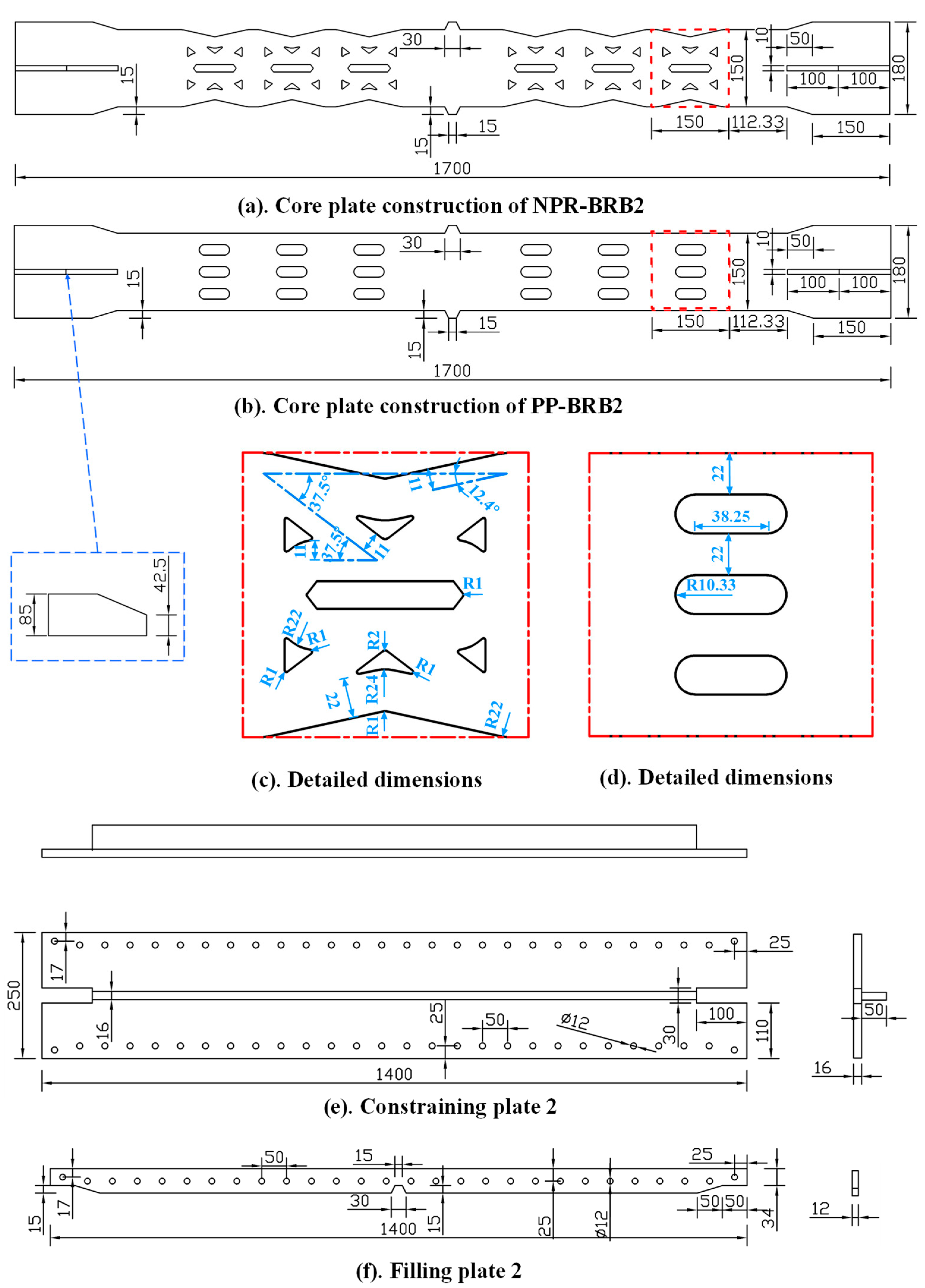
Based on differences in the dimensional parameters of the auxetic perforated cells and the core plate materials used, the specimens were divided into two groups. These two factors are setup in an attempt to analyze the effect of the dimensional changes of the Composite Auxetic Cellular Units and the effect of Q235 steel versus LY160 mild steel as the core plate material on the energy dissipation performance of BRBs. The aim of this paper is to explore the problem of improving the comprehensive energy dissipation capacity of BRB and alleviating its lack of fatigue resistance by studying these influencing factors. The first group included NPR-BRB1 and PP-BRB1; both used Q235B as the core plate material, with an energy-dissipating segment width of 100 mm. Each energy-dissipating segment comprised five cellular units, and the lowest cross-sectional weakening ratio (φ) and porosity (ω) per unit were 68% and 43.89%, respectively, for both specimens. The second group consisted of NPR-BRB2 and PP-BRB2, with LY160 as the core plate material and an energy-dissipating segment width of 150 mm. Each energy-dissipating segment in this group included three cellular units, and both specimens had the same φ (41.33%) and ω (15.01%) per unit. Minor dimensional differences existed between the groups. The shapes and dimensions are shown in Figure 3. A detachable constraint structure was designed to facilitate the observation of the core plate damage after the test. It consisted of two T-shaped constraint plates attached with high-strength bolts (45 mm long and 12 mm diameter) through the filler plates. A 1 mm gap was maintained between the core plate and the constraint plates. Additionally, a 1 mm thick rubber pad was used to wrap the core plate without adhesive to reduce out-of-plane buckling and friction between the core plate and the constraint.
The constraint plates were 1400 mm long, 202 mm wide, and 10 mm thick and had two rows of 12 mm bolt holes spaced 50 mm apart to connect to the filler plates. The filler plates (1400 mm long) were aligned precisely with the constraint plates for bolting. Their interior matched the core plate contour with a 1 mm gap to prevent lateral expansion during compression and reduce friction. The core plate was 1700 mm long and 10 mm thick, with a 100 mm wide energy-dissipating section. At the mid-length, trapezoidal limiters restricted the relative motion between the core plate and the constraint. Stiffening ribs (10 mm thick) were welded on the top and bottom surfaces at both ends of the connection sections. The connection plates (200 mm × 200 mm × 30 mm) were welded to both ends of the core plate and aligned at the center. Each plate had four 35 mm diameter holes for attachment to the testing machine.
Each BRB specimen included two perforated sections on the core plate, positioned between the limiters and transition zones. Each section contained five identical perforated cells (105 mm long and 100 mm wide) to match the core plate’s energy-dissipating width. Individual perforated cells were designed with identical porosity and cross-sectional weakening rates of 44.01% and 68.00%, respectively, to compare the performance of the PP-BRBs and NPR-BRBs with the same material. The cell dimensions are shown in Figure 3 and Figure 4, the schematic diagram of each component and the assembly drawing of the specimen are shown in Figure 1. Only one row of perforations was used on the core plate due to manufacturing limitations. Smaller perforations would increase the number and cost and result in larger laser cutting tolerances that might compromise precision. All components, excluding bolts, were laser-cut from the Q235B steel plate.
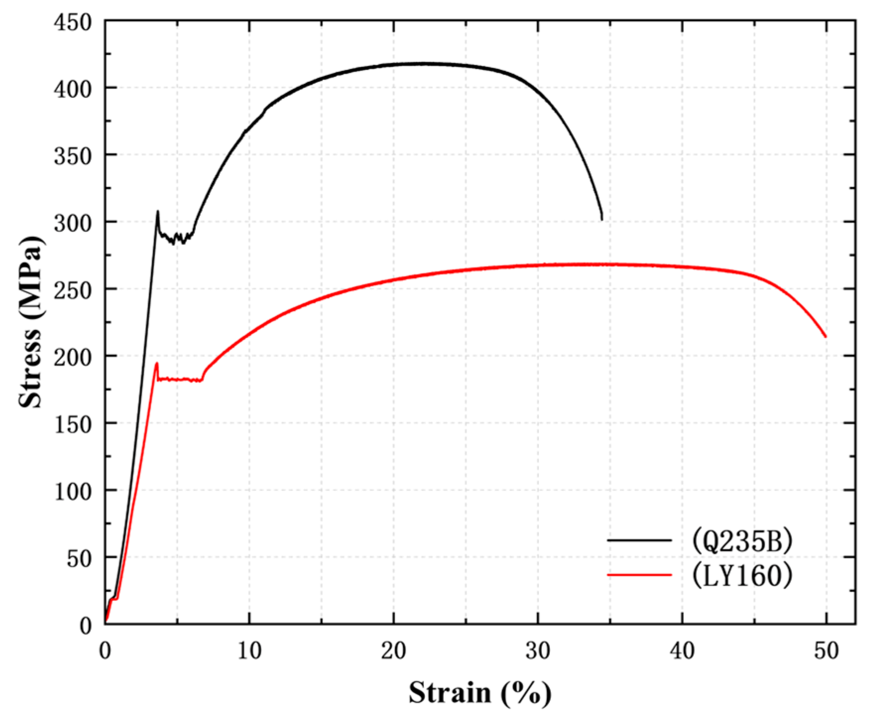
The material properties of the Q235B and LY160 steel used for the specimens were tested following China’s GB/T228.1-2021 standard for room-temperature tensile testing of metals [59] to ensure high manufacturing precision of the core plate. The core plate shapes and perforations were fabricated using computerized numerical control (CNC) machining; its tolerance is ±0.01 mm. The stress, strain, and other data of the specimen are recorded by the high-precision sensors equipped with the universal testing machine (HUT106A). The stress–strain curves are presented in Figure 5, and the average values of the material properties are listed in Table 1.

3.2. Test Setup and Loading Protocol

A 4000 KN MTS dynamic actuator was used for loading, with a displacement stroke of ±400 mm. The connection plates were welded to each end of the BRB and bolted to the reaction frame and actuator. The setup included a fixed frame, reaction supports, and the actuator, with the frame anchored to the floor and a guide rail allowing the actuator to perform tension and compression cycles. All connections used high-strength bolts. Figure 6 illustrates the setup with the specimen mounted on the actuator system.
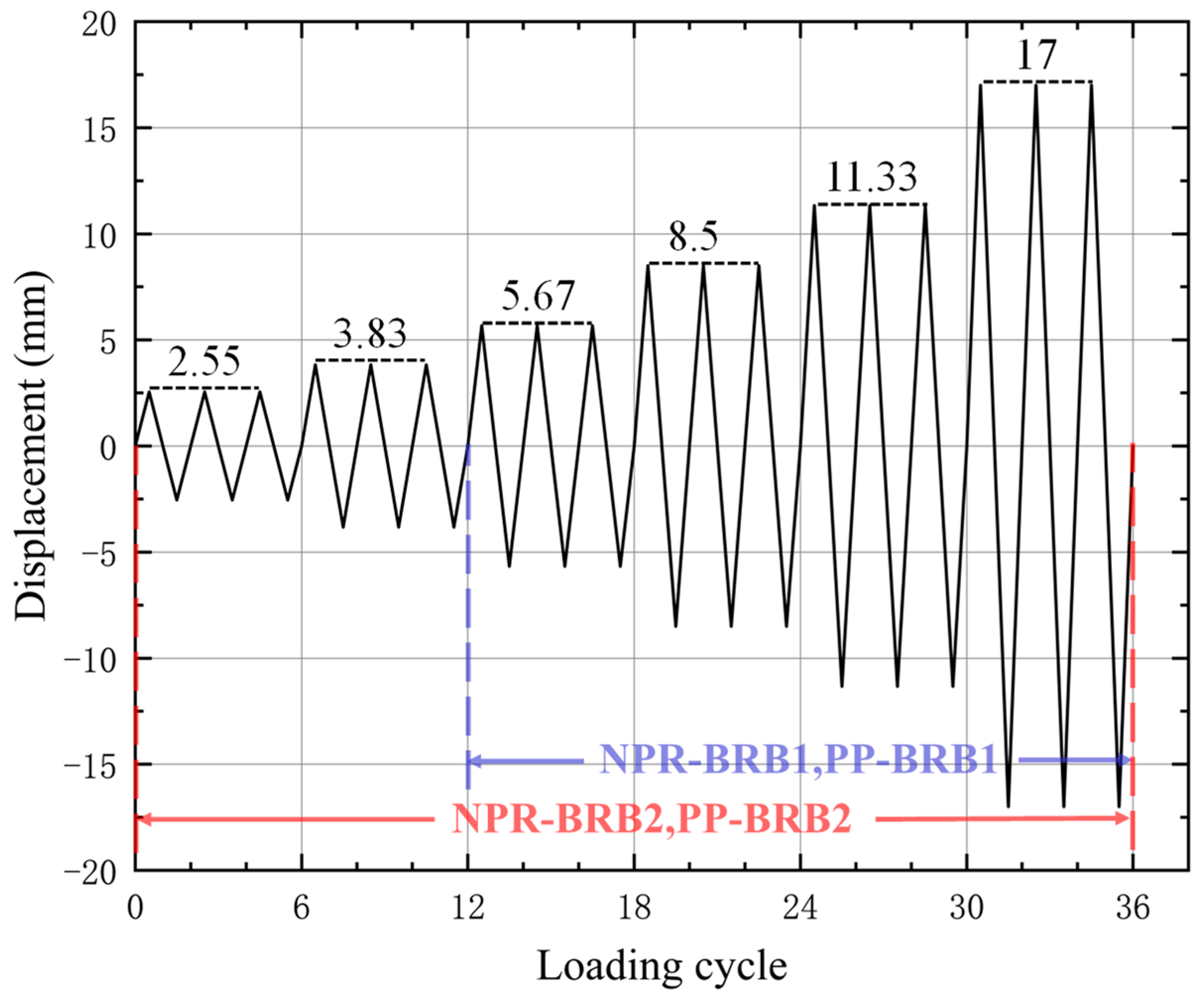
The axial load was measured by a load cell within the MTS actuator, and axial deformation was recorded by three displacement transducers placed at each end. Cyclic loading was displacement-controlled. Since the second group of specimens had a smaller porosity and fewer auxetic perforations compared to the first group, their working displacement range under tension–compression loading was relatively limited. To better investigate the mechanical response of the second group under external loading, two additional smaller amplitude levels—specifically L/667 and L/444—were incorporated into the loading protocol for this specimen group. In Group 1 (NPR-BRB1, PP-BRB1), the displacement amplitudes were L/300 (5.67 mm), L/200 (8.5 mm), L/150 (11.33 mm), and L/100 (17 mm), with three cycles at each amplitude. In Group 2 (NPR-BRB2, PP-BRB2), the displacement amplitudes were L/667 (2.55 mm), L/444 (3.83 mm), L/300 (5.67 mm), L/200 (8.5 mm), L/150 (11.33 mm), and L/100 (17 mm). L represents the core plate length with a value of 1700 mm, with three cycles at each amplitude, as illustrated in Figure 7.

4. Experimental Results and Discussion

4.1. Failure Modes

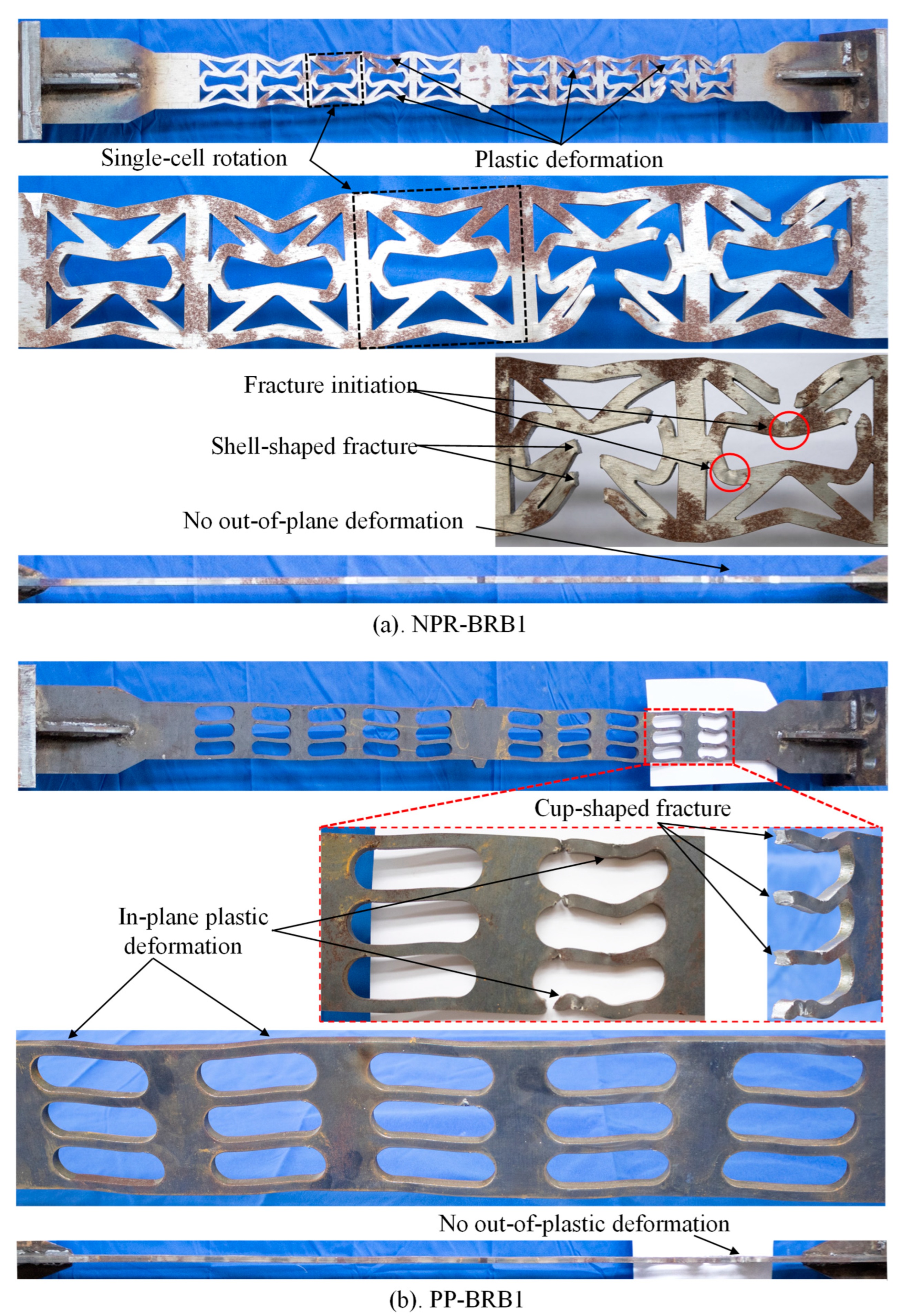
Figure 8 and Figure 9 illustrate the failure modes of the specimens. In both control groups, the regions outside the perforated energy-dissipation sections of the core plate remained in an elastic state, showing no in-plane deformation or out-of-plane buckling. All fractures in the four specimens occurred near the end of the stiffening rib without signs of significant out-of-plane buckling. This lack of buckling is attributed to the in-plane deformation of the perforated cellular units, which inhibit out-of-plane buckling of the BRB—a finding previously reported by Zhang et al. [48]. In addition to the fractured cells, other units displayed minor in-plane deformation, enabling more uniform energy dissipation. In Control Group 1, the NPR-BRB1’s failure extended beyond a single cell, predominantly occurring in the first and second cells nearest to the loading end. The first cell exhibited two ligament fractures, whereas the second cell sustained three fractures, extending from the weakest section to the double-arrow auxiliary structure region. This distribution aligns with the anticipated failure mode because the in-plane deformation of the cellular units caused significant deformation at the vertices of the double-arrow auxiliary structures. As shown in Figure 8, the NPR-BRB1 exhibited considerable deformation across most cells, suggesting that multiple units distributed seismic energy, mitigating stress concentration. In contrast, the PP-BRB1 demonstrated ligament fractures concentrated at the same critical section of a single cell, with no out-of-plane buckling in the fractured cell. The core plate showed widthwise deformation due to minor in-plane deformation of other cells. The NPR-BRB1 displayed more pronounced in-plane deformation across the cells, demonstrating the high deformability of the combined auxetic cellular units.
In Control Group 2, fractures in both specimens occurred at the end of the perforated section furthest from the loading end, with ligament fractures concentrated in a single cell. The other cells displayed no significant out-of-plane buckling. The NPR-BRB2 exhibited fractures localized at the same critical section within a single cell in the designed weakest section. In contrast, the other cells displayed varying degrees of minor in-plane plastic deformation. However, fractures were observed in two sections of the PP-BRB2 within the same cell, with ligaments on the top, bottom, and middle portions breaking at critical sections. This concentrated failure may result from the lower sectional weakening ratio, leading to limited energy distribution across the cells and intensified stress concentration during load transformation.
As seen in Figure 8 and Figure 9, PP-BRB1 exhibited slight necking at the fracture location, as well as compression-induced instability deformation across the width. Since softer LY160 steel was used in the PP-BRB2, the pronounced necking at the fracture site indicated soft steel tensile failure, resembling LY160’s behavior in the tensile tests. Both PP-BRB specimens showed cup-shaped fracture surfaces. Conversely, the NPR-BRB specimens exhibited relatively flat, shell-like fracture surfaces, a result of the unique deformation mechanism of the composite auxetic cellular units. This mechanism enabled repeated widthwise bending at the weakest section to achieve auxetic deformation, manifesting as cyclic folding behavior of each ligament at the corners, resulting in brittle, fatigue-induced fractures at critical sections. These observations confirm that the unique deformation mechanism of the NPR-BRB effectively distributes input energy across the cells due to auxetic behavior, improving energy dissipation capacity.

4.2. Hysteresis Curves

The hysteresis curves for the two control groups are illustrated in Figure 10. All specimens except PP-BRB1 demonstrated full and stable hysteresis loops.
In Control Group 1, NPR-BRB1’s ultimate tensile and compressive load capacity was significantly lower than that of PP-BRB1 despite similar porosity and sectional weakening ratios. This difference may be attributed to the bending deformation observed at the critical sections of the cellular units in the NPR-BRB1 under axial loading. The initial bent configuration of the cellular unit’s critical section contrasts with the unbent ligaments in PP-BRB1; thus, PP-BRB1’s compressive behavior was more similar to Euler’s first law. Consequently, NPR-BRB1’s load capacity was comparatively lower. Additionally, PP-BRB1’s hysteresis loop had a diamond shape, whereas NPR-BRB1’s curve approximated a parallelogram, indicating a fuller and more stable loop and suggesting superior energy dissipation for NPR-BRB1 than for PP-BRB1.
In Control Group 2, the hysteresis curves of both specimens were nearly identical in terms of ultimate load capacity, fullness, and stability. The PP-BRB2 exhibited slightly higher ultimate tensile strength, whereas the NPR-BRB2 showed a marginally higher ultimate compressive strength. Failure points occurred on the first hysteresis loop at a displacement amplitude of L/100. The deformation was confined to a single cell, particularly in the weakest section, reducing the BRB’s ultimate load-bearing displacement.
The control groups’ hysteresis curves suggest a correlation between the BRB’s material strength and sectional weakening ratio. The PP-BRB exhibited significantly higher load capacity under sustained tensile and compressive loads than the NPR-BRB at a weakening ratio of 68%; however, the load capacities of both were similar when the ratio was reduced to 41.33%. The primary difference between the two PP-BRB specimens was the steel material used in the core plates. Specimens fabricated with LY160 steel exhibited fuller hysteresis curves and less pronounced stiffness hardening after yielding under an axial force than those made with Q235B steel. Both NPR-BRB specimens demonstrated full hysteresis curves because their auxetic cellular units dissipated energy through bending deformation in the weakest sections rather than relying solely on material strength and plastic deformation.

4.3. Compressive Strength Adjustment Factor

Due to an increase (decrease) in the cross-sectional area under compression (tension), as well as contact and friction between the core plate and the constraint units, the BRB’s axial forces are asymmetric under tensile and compressive loads. This load asymmetry, or axial force asymmetry, is commonly evaluated using the compressive strength adjustment factor β, which is calculated as follows:
β = N C i , m a x N T i , m a x
where  N C i , m a x and  N T i , m a x represent the maximum compressive and tensile forces (in KN) in the i-th hysteresis loop, respectively. We analyzed the last hysteresis loop at the largest magnitude. According to standard requirements [60], the BRB’s compressive strength adjustment factor β should be less than the limit of 1.3. All specimens satisfied this requirement (Table 2).
We elucidated the potential impact of the auxetic cellular unit’s material, the lowest weakening ratio, and the concave angle α on the hysteresis performance of the NPR-BRB.

4.4. Ductility and Energy Dissipation Capacity

The ductility and plastic deformation capacity of the BRB specimens were evaluated using the cumulative plastic deformation (CPD) coefficient, which is defined mathematically as:
C P D = i = 1 n 2 Δ i , m a x + Δ i , m i n Δ y 4
where  Δ i , m a x and  Δ i , m i n denote the maximum compressive and tensile displacements (in mm) of the i-th loop, and  Δ y represents the yield displacement (in mm). According to established standards [60], the CPD of the BRB specimens must meet certain requirements. As presented in Table 2, PP-BRB1 exhibited premature fracture under tensile loading due to the excessively high porosity of its perforations and the consequently reduced ligament cross-sectional area at the weakest section. Consequently, while the other three specimens achieved CPD values exceeding 200—demonstrating superior plastic deformation capacity—PP-BRB1 failed to meet this performance threshold.
The energy dissipation capacity of the BRB is quantified by the area enclosed within the hysteresis loops for each loading cycle. Table 2 indicates that although the NPR-BRB1 had lower energy dissipation than the PP-BRB1, it reached the yield point at lower loads, initiating earlier energy dissipation, which is advantageous for increasing the BRB’s responsiveness during minor earthquakes. It should be noted that yielding refers to in-plane auxetic deformation. Table 2 lists the energy dissipation capacity of the four specimens, showing that NPR-BRB had a lower energy dissipation capacity than PP-BRB. Additionally, the energy dissipation was much lower in the first group than in the second one, indicating a strong correlation between the BRB’s energy dissipation performance and the sectional weakening ratio. For further evaluation, the energy dissipation coefficient  ψ and the equivalent viscous damping ratio  ζ e q were calculated as follows:
ψ = E l o n p S C + S T
ζ e q = ψ 2 π = E l o n p 2 π S C + S T
where  E l o n p represents the area of a single hysteresis loop during a loading cycle, and  S C and  S T are the triangular areas formed by the peak tensile or compressive load points on the displacement axis and the origin. Table 2 displays the  ψ and  ζ e q values for the specimens. The NPR-BRB1 exhibited higher  ψ and  ζ e q values than the PP-BRB1, which was attributed to NPR-BRB1’s superior deformation capacity. The plastic deformation of PP-BRB1 is mainly caused by tension, while that of NPR-BRB1 is mainly induced by bending; both can dissipate significant amounts of energy. Conversely, the NPR-BRB2 and PP-BRB2 had comparable  ψ and  ζ e q values because NPR-BRB2’s lower sectional weakening ratio resulted in lower auxetic deformation. Therefore, energy dissipation occurred primarily by plastic deformation in the weakest section.

5. Numerical Simulation Study

5.1. Validation of the Numerical Model

Finite element simulations were conducted using the ABAQUS/Standard solver to compare with the experimental results and investigate the effects of the core plate material and perforated auxetic honeycomb cell parameters on the NPR-BRB’s performance. The BRB components consisted of Q235 and LY160 steel, i.e., low-carbon steel. Thus, a nonlinear combined isotropic-cyclic hardening intrinsic model [48,49,61] was chosen in ABAQUS to represent the material properties. The parameters are listed in Table 3.
In the finite element model, since a 1 mm rubber layer does not prevent the out-of-plane buckling of the core plate, a 1 mm thick gap is used instead of the rubber layer, and the interaction between the core plate and the restraint units was defined as surface-to-surface contact. It was applied to all surfaces, including self-contact. Tangential behavior was modeled with a penalty function and a friction coefficient of 0.3, whereas normal behavior was modeled as hard contact. Although a gap existed initially between the core plate and the restraint units, multiple contact points appeared under compression as higher-order out-of-plane buckling occurred. We defined contact on the entire surface to enable the solver to detect the contact between the core plate and restraint units. The pre-tightening force of the bolts was ignored, and the nut and bolt head were fixed to the contact surface of the restraint plate to simplify the model. Binding constraints were applied between the core plate and the stiffening ribs, as well as between the restraint and the filler plates. Additionally, a reference point was created on the right surface to simulate the loading end. The coupling point was constrained to allow axial displacement only while the left surface was fixed. All components were meshed with C3D8R elements, with a mesh size of 3 mm for the core plate yielding section and 10 mm for the other components. A first-order buckling mode was chosen as an initial defect to account for inherent defects. The defect factor was 1/1000 of the support’s length. The finite element model of the NPR-BRB is shown in Figure 11.
The finite element model was analyzed with controlled dimensions and boundary conditions consistent with the experiment, revealing a high degree of agreement with the experimental results. A comparison of the failure modes and stress–strain results (Figure 12) between the test and numerical model showed that the total equivalent plastic strain state (PEEQ) in the numerical model accurately described the BRB’s deformation pattern. In the comparison of NPR-BRB1’s test and simulated results, multiple plastic deformation zones aligned well. The positions marked by red ellipses exhibit inward deformation, and the central cell between the left and right energy-dissipating segments indicates rotation. The PEEQ distribution of the NPR-BRB2 matched the deformation distribution of the test specimen. Notably, the maximum deformation of the NPR-BRB1 occurred near the loading end, whereas that of the NPR-BRB2 occurred in the cell farthest from the loading end, as verified by the PEEQ values. This result was consistent with the failure modes of both specimens. Load–displacement hysteresis curves were obtained from both experiments and numerical simulations. For each corresponding hysteresis loop in these two types of curves, their loop areas were extracted to calculate the error percentage. For the four specimens, the error percentage of each hysteresis loop area was computed individually. The average error percentage of the load–displacement curves was then obtained by dividing the sum of all error percentages by the total number of hysteresis loops, with the result being 7.63%. As show in Figure 10, a comparison of the hysteresis curves derived from the numerical simulations and experiments demonstrated a good agreement. Thus, the proposed finite element model accurately simulates the test specimens’ performance, providing a reliable basis for the subsequent analysis of factors influencing the NPR-BRB’s performance.
In Figure 12c, a finite element model is used to demonstrate the auxetic deformation of the novel auxetic cell on the core plate of the NPR-BRB under tension and compression. Taking the initial state as an example, the straight-line distance between the two five-pointed stars on the bending points of the two ligaments is defined as the width of the cell, while the length is defined as the distance between the two vertical ligaments. This definition yields a red rectangular region, which is used to determine the deformation of the cell. When the cell is compressed transversely, the width of the cell is the distance between the two triangles; it can be observed that the cell undergoes transverse compressive deformation accompanied by vertical contraction. When the cell is stretched transversely, the width of the cell is the distance between the two rhombuses, and this distance increases, indicating vertical expansion during transverse stretching. This phenomenon conforms to the deformation characteristics and definition of auxetics, confirming that the newly designed composite cell exhibits auxetic properties.

5.2. Material Influence

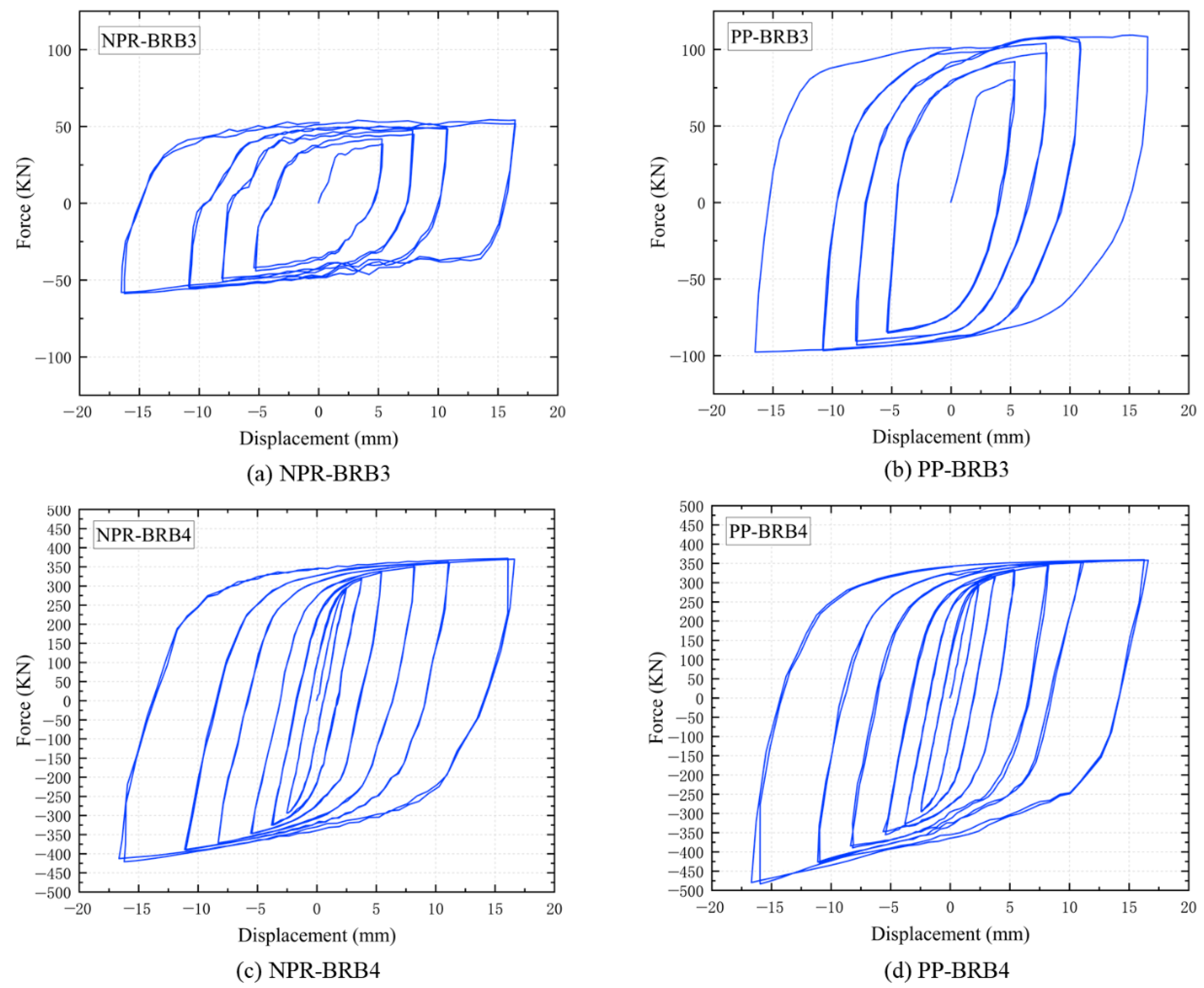
Two materials were used for the BRB core plates to investigate the impact of the material on the performance of the perforated BRBs. The NPR-BRB1’s and PP-BRB1’s core plate materials were changed to LY160, and the NPR-BRB2’s and PP-BRB2’s core plate materials were replaced with Q235B. All other components remained unchanged. We obtained four new specimens (NPR-BRB3, PP-BRB3, NPR-BRB4, and PP-BRB4), which were analyzed using a simulation.
The PEEQ of the four specimens are shown in Figure 13. To better visualize the deformation in perforated BRBs, the transition, connection, and restraint sections of the core plate were hidden to clarify the deformation in the perforated BRBs. These areas do not experience plastic strain in the simulation. The results show that the maximum deformation in the LY160 core plate models occurred farther from the loading end than in the experiment. In contrast, in the Q235B core plate models, the maximum deformation was closer to the loading end, and the deformation pattern differed from that of similar perforated specimens. The top view of the eight core plate models is displayed in Figure 14, with Y-axis displacements magnified threefold. The deformation patterns reveal that the LY160 core plates showed greater out-of-plane deformation and a higher number of waves than the Q235B core plates, confirming that LY160 provided higher deformability. Additionally, the PEEQ values indicate that BRBs with LY160 core plates experienced larger deformations under the same conditions due to the LY160’s lower yield strength.
Figure 15 shows the hysteresis curves for the four models with different core plate materials. The comparison reveals that BRBs with LY160 core plates exhibited fuller and more stable hysteresis loops, whereas the Q235-based models showed more pronounced tensile-compressive asymmetry, with lower tensile than compressive bearing capacity, consistent with the experimental results. This finding confirms that the LY160 provided superior deformability for the BRBs. The performance indices for the four models with different core plate materials are listed in Table 4. A positive correlation exists between material strength and the maximum tensile-compressive load; higher loads correspond to larger hysteresis loop areas. The experimental results indicate that the NPR-BRB3 (with an LY160 core plate) had a lower compressive strength adjustment factor than the NPR-BRB1, with values of 1.288 and 1.13, respectively, suggesting improved stability of the NPR-BRB3. The comparisons of the equivalent viscous damping coefficients and CPD indicate that BRBs with LY160 core plates exhibited superior performance under identical conditions, a finding consistent for the remaining three specimens.
For the same material and the lowest cross-section weakening ratio, the auxetic honeycomb cell exhibited initial bending due to its concave angle, resulting in lower yield strength but higher deformation under tensile-compressive loads than the perforated cells with the positive Poisson’s ratio. This finding suggests that the concave angle affected the energy dissipation capacity of the 2D concave honeycomb structures. Additionally, the cross-section weakening ratio significantly influenced the performance of the NPR-BRBs. Therefore, further analysis of the relationship between the concave angle, cross-section weakening ratio, and perforated BRB performance is crucial to increase the understanding of the BRB’s energy dissipation mechanisms and optimize its performance.

5.3. Parameter Effects

5.3.1. Influence of Reentrant Angle

We used finite element methods to simulate the performance of the NPR-BRBs with different reentrant angles. All models had the same section weakening ratio and a cell unit size of 150 mm × 150 mm. The component dimensions remained unchanged. LY160 was the core plate material for all specimens. The reentrant angle α and the section weakening parameters are provided in Table 4. As a critical control parameter, α must be appropriately chosen. If it is too large, it constrains the design space for the internal reentrant triangles, making the design infeasible; conversely, if it is too small, it limits the design space for the external reentrant triangles. Therefore, we used α values from 32.5° to 42.5°.
The backbone curve is an indicator of the BRB’s force and deformation, showing the maximum tension and compression peaks during the loading cycles. As shown in Figure 16, the backbone curves of the specimens show only minor differences, with slight variations at the extreme displacement points. As the reentrant angle decreased, the peak tension increased slightly with each loading cycle, and the ultimate bearing capacity rose, indicating that a smaller reentrant angle resulted in higher tensile and compressive strength of the BRB.
We computed other key energy dissipation performance metrics, including the equivalent viscous damping ratio, the compressive strength adjustment factor, and the CPD coefficient (Table 4). The equivalent viscous damping ratio was derived from the last loading cycle. As the reentrant angle increased, the peak tension and compression loads of all samples decreased, consistent with the observations of the backbone curves. The variation in the compressive strength adjustment factor was minor. Notably, the sum of the hysteresis loop areas decreased. The hysteresis loop area depends on the magnitude of the peak tensile and compression loads and the curve’s fullness. Its trend aligns with that of the ultimate tension–compression loads.
The equivalent viscous damping ratio was positively correlated with the reentrant angle, with all samples exceeding a damping ratio of 200. The likely reason is that a larger reentrant angle increases the BRB’s deformation capacity. The CPD, which measures the BRB’s deformation capacity, increased with the reentrant angle, validating the trend in the equivalent viscous damping ratio. The BRB’s bearing capacity and hysteresis loop area were higher at a smaller reentrant angle, and the equivalent viscous damping ratio and CPD were lower. Therefore, the reentrant angle should be appropriate because very large or small values may negatively impact the BRB’s energy dissipation performance.

5.3.2. Influence of Section Weakening Ratio

This study examined the impact of different section weakening ratios on sample performance. The control angle α was 37.5° for all specimens. The backbone curves for all samples showed a marked downward trend in peak bearing capacity and yield strength as the section weakening ratio increased, indicating a significant effect of the section weakening ratio on the sample’s load-bearing capacity. However, the backbone curve alone is insufficient to assess the BRB’s energy dissipation performance. As shown in Table 4, the total hysteresis loop area and bearing capacity significantly decreased as the section weakening rate increased. The compressive strength adjustment factor decreased with an increase in the section weakening ratio, indicating that as the openings increased, the BRB’s stability decreased. A compressive strength adjustment factor closer to 1 indicated higher BRB stability. The NPR-BRB11 had the highest stability with a uniformity coefficient of 1.027.
The equivalent viscous damping ratio and the CPD increased and decreased, reaching their maximum values of 0.55 and 305.33 at a section weakening rate of 57%. As shown in Table 4, the NPR-BRB11 performed optimally regarding the uniformity coefficient, equivalent viscous damping ratio, and CPD, with a thickness of 16 mm.
Previous studies have suggested that samples with higher section weakening ratios had more pronounced auxetic behavior. This ratio provides more information than relying solely on the material’s tensile and compressive performance. This dual energy dissipation mechanism enables the BRB to deform in-plane and out-of-plane. The section weakening ratio influenced the deformation capacity of the auxetic cells and the stress concentration. Based on previous research, we deduce that a higher section weakening ratio results in less pronounced auxetic behavior of the cells. During BRB deformation, the energy dissipation is concentrated in a single cell’s weakest section where widthwise opening and closing deformation occur, resulting in fatigue failure under cyclic loading. This phenomenon is observed in the specimen failure diagram.

6. Conclusions

This study innovatively proposed a composite auxetic cell design consisting of perforations of the BRB’s core plate, creating the NPR-BRB. Experimental and finite element simulations were conducted to examine the effects of the material, reentrant angle, and section weakening ratio on the NPR-BRB’s energy dissipation performance and deformation under cyclic loading. The key findings are summarized as follows:
In addition to the same section weakening ratio and porosity, the NPR-BRBs exhibited lower yield strength and ultimate tensile and compressive capacity than the conventional PP-BRBs. However, the NPR-BRBs had a higher equivalent viscous damping ratio than the PP-BRBs, with a fuller, more stable hysteresis curve, indicating better energy dissipation performance. This phenomenon stems from the distinctive deformation mechanism of NPR-BRBs with auxetic structures, which fundamentally differs from conventional positive Poisson’s ratio configurations. enabling greater plastic deformation under tension–compression loading while demonstrating superior ductility capacity.
Different deformation mechanisms of NPR-BRBS and PP-BRBS resulted in two fracture patterns observed in the experiments: cup-shaped fracture surfaces due to tensile failure and shell-shaped fracture surfaces due to fatigue failure. When the NPR-BRBS is subjected to external tensile and compressive loads, each boomerang-shaped ligament of the composite metamaterial cell undergoes in-plane bending deformation. This process dissipates energy more continuously and effectively than the PP-BRBS. All specimens’ compressive strength adjustment factors were below 1.3, and except for the PP-BRB1, the CPD of the other specimens exceeded 200.
All NPR-BRB specimens exhibited in-plane deformation and negligible out-of-plane deformation in the experiments and numerical simulations, indicating excellent capability in delaying out-of-plane buckling. The failure of specimens with higher section weakening ratios occurred closer to the loading end, with significant deformation in multiple segments of the energy-dissipating section. In contrast, the failure of specimens with lower section weakening ratios occurred further from the loading end, with deformation observed only in a single cell. It can be observed that the force transmission and degree of dissipation between cells in NPR-BRBs are related to the weakening ratio of the weakest cross-section of the cells. This study can only provide this general trend, as the determination of the optimal weakening ratio for the weakest cross-section is beyond the scope of this research.
After substituting Q235 with LY160 for the core plate material, the simulation results indicated that the LY160 samples exhibited lower yield strength, load-bearing capacity, and a compressive strength adjustment factor. However, the equivalent viscous damping ratio and cumulative plastic strain were higher. The LY160-based samples exhibited greater maximum deformation than those with Q235, and the failure locations were further from the loading end. The deformation in the energy-dissipating segment was more evenly distributed across multiple cells, suggesting that LY160 resulted in higher BRB performance. Compared to Q235 steel, LY160 steel demonstrates superior energy dissipation capacity, greater plastic deformation, and enhanced ductility.
The reentrant angle had a negligible effect on BRB performance, whereas the section weakening ratio had a significant influence. As the section weakening ratio of the six samples increased, the ultimate loading capacity of the NPR-BRB decreased significantly, and the tension–compression uniformity coefficient decreased. However, the equivalent viscous damping ratio and CPD increased and decreased, and the maximum values occurred at a section weakening rate of 57%. However, this does not necessarily imply optimal energy dissipation or ductility at this point; further studies are needed to determine the ideal section weakening ratio.

Author Contributions

Writing—original draft, Y.C.; Formal analysis, Y.C.; Conceptualization, Y.C. and Z.Z.; Project administration, X.W.; Funding acquisition, X.W.; Methodology, X.W.; Writing—review and Editing, X.W.; Resources, K.W.; Data curation, K.W.; Investigation, Z.Z. All authors have read and agreed to the published version of the manuscript.

Funding

This research was funded the National Natural Science Foundation of China (52268037).

Data Availability Statement

The raw data supporting the conclusions of this article will be made available by the authors on request.

Acknowledgments

We are extremely grateful to the College of Architecture and Civil Engineering of Kunming University for their support and assistance in providing the testing site.

Conflicts of Interest

The authors declare no conflicts of interest.

References

  1. Zhong, J.; Zhao, C.; Liu, Y.; Ren, J.; Yang, C.; Zhang, Z. Meta-materials of Re-entrant Negative Poisson’s Ratio Structures Made from Fiber-Reinforced Plastics: A Short Review. Fibers Polym. 2024, 25, 395–406. [Google Scholar] [CrossRef]
  2. Ren, X.; Das, R.; Tran, P.; Ngo, T.D.; Xie, Y.M. Auxetic metamaterials and structures: A review. Smart Mater. Struct. 2018, 27, 023001. [Google Scholar] [CrossRef]
  3. Shuaibu, A.S.; Deng, J.; Xu, C.; Ade-Oke, V.P.; Aiyu, A.; Momoh, D. Advancing auxetic materials: Emerging development and innovative applications. Rev. Adv. Mater. Sci. 2024, 63, 20240021. [Google Scholar] [CrossRef]
  4. Alderson, A. A triumph of lateral thought. Chem. Ind. 1999, 17, 384–391. [Google Scholar]
  5. Grima, J.N.; Caruana-Gauci, R.; Attard, D.; Gatt, R. Three-dimensional cellular structures with negative Poisson’s ratio and negative compressibility properties, Proceedings of the Royal Society A: Mathematical. Phys. Eng. Sci. 2012, 468, 3121–3138. [Google Scholar] [CrossRef]
  6. Mahdinejad Gorji, J.; Payganeh, G.; Moradi-Dastjerdi, R. Mechanical and energy absorption behavior of an innovative high-performance auxetic structure. Mech. Based Des. Struct. Mach. 2024, 52, 2316–2335. [Google Scholar] [CrossRef]
  7. Imbalzano, G.; Tran, P.; Ngo, T.D.; Lee, P.V.S. A numerical study of auxetic composite panels under blast loadings. Compos. Struct. 2016, 135, 339–352. [Google Scholar] [CrossRef]
  8. Tian, Z.; Shi, S.; Liao, Y.; Wang, W.; Zhang, L.; Xiao, Y. Energy Absorption Mechanisms of Riveted and Assembled Double-Trapezoidal Auxetic Honeycomb Core Structures Under Quasi-Static Loading. J. Compos. Sci. 2025, 9, 89. [Google Scholar] [CrossRef]
  9. Indreș, A.I.; Constantinescu, D.M.; Mocian, O.A.; Sorohan, Ș. Particularities on the Low-Velocity Impact Behavior of 3D-Printed Sandwich Panels with Re-Entrant and Honeycomb Core Topologies. J. Compos. Sci. 2024, 8, 426. [Google Scholar] [CrossRef]
  10. Kun, Y.; Fei, T.; Bo, W.Y.; He, H.Y. Study on impact energy absorption performance and optimization of negative Poisson’s ratio structure. J. Braz. Soc. Mech. Sci. Eng. 2023, 45, 328. [Google Scholar] [CrossRef]
  11. Donoghue, J.P.; Alderson, K.L.; Evans, K.E. The fracture toughness of composite laminates with a negative Poisson’s ratio. Phys. Status Solidi B 2009, 246, 2011–2017. [Google Scholar] [CrossRef]
  12. Bora, K.M.; Varshney, S.K.; Kumar, C.S. Rounded corner thicken strut re-entrant auxetic honeycomb: Analytical and numerical modeling. Mech. Res. Commun. 2024, 136, 104246. [Google Scholar] [CrossRef]
  13. Zhang, X.Y.; Wang, X.Y.; Ren, X.; Xie, Y.M.; Wu, Y.; Zhou, Y.Y.; Wang, S.L.; Han, C.Z. A novel type of tubular structure with auxeticity both in radial direction and wall thickness. Thin-Walled Struct. 2021, 163, 107758. [Google Scholar] [CrossRef]
  14. Luo, C.; Han, C.Z.; Zhang, X.Y.; Zhang, X.G.; Xie, Y.M. Design, manufacturing and applications of auxetic tubular structures: A review. Thin-Walled Struct. 2021, 163, 107682. [Google Scholar] [CrossRef]
  15. Yu, X.; Zhou, J.; Liang, H.; Jiang, Z.; Wu, L. Mechanical metamaterials associated with stiffness, rigidity and compressibility: A brief review. Prog. Mater. Sci. 2018, 94, 114–173. [Google Scholar] [CrossRef]
  16. Zawistowski, M.; Poteralski, A. Parametric optimization of selected auxetic structures, Multiscale and Multidisciplinary Modeling. Exp. Des. 2024, 7, 4777–4789. [Google Scholar] [CrossRef]
  17. Wang, Y.; Zeng, H.; Nie, B.; Jia, F.; Gao, Q. Energy absorption characteristics of carbon fiber reinforced plastic/aluminum hybrid materials double arrow-head auxetic structure. J. Sandw. Struct. Mater. 2024, 26, 490–506. [Google Scholar] [CrossRef]
  18. Lu, F.; Wei, T.; Zhang, C.; Huang, Y.; Zhu, Y.; Rui, X. A novel 3D tetra-missing rib auxetic meta-structure with tension/compression-twisting coupling effect. Thin-Walled Struct. 2024, 199, 111764. [Google Scholar] [CrossRef]
  19. Nickabadi, S.; Sayar, M.A.; Alirezaeipour, S.; Ansari, R. Optimizing an auxetic metamaterial structure for enhanced mechanical energy absorption: Design and performance evaluation under compressive and impact loading. J. Sandw. Struct. Mater. 2024, 26, 1129–1164. [Google Scholar] [CrossRef]
  20. Lakes, R. Foam structures with a negative Poisson’s ratio. Science 1987, 235, 1038–1040. [Google Scholar] [CrossRef]
  21. Hosseini, M.; Mazaheri, H. Mechanical behavior of graded combined auxetic-honeycomb structures. Int. J. Mech. Sci. 2024, 276, 109223. [Google Scholar] [CrossRef]
  22. Meng, Z.; Xu, Y.; Xie, J.; Zhou, W.; Bol, R.J.M.; Liu, Q.; Savjia, B. Unraveling the reinforcing mechanisms for cementitious composites with 3D printed multidirectional auxetic lattices using X-ray computed tomography. Mater. Des. 2024, 246, 113331. [Google Scholar] [CrossRef]
  23. Chen, M.; Fang, S.; Wang, G.; Xuan, Y.; Gao, D.; Zhang, M. Compressive and flexural behaviour of engineered cementitious composites based auxetic structures: An experimental and numerical study. J. Build. Eng. 2024, 86, 108999. [Google Scholar] [CrossRef]
  24. Bao, Y.; Wei, Z.; Jia, Z.; Wang, D.; Zhang, X.; Kang, Z. Mechanical metamaterial design with the customized low-frequency bandgap and negative Poisson’s ratio via topology optimization. Extrem. Mech. Lett. 2024, 67, 102–124. [Google Scholar] [CrossRef]
  25. Chen, Y.; Zhou, Y.; Hu, Z.; Lu, W.; Li, Z.; Gao, N.; Liu, Y. Gelatin-based metamaterial hydrogel films with high conformality for ultra-soft tissue monitoring. Nano-Micro Lett. 2023, 16, 34. [Google Scholar] [CrossRef] [PubMed]
  26. Pan, K.; Ding, J.; Zhang, W.; Zhao, S. The negative Poisson’s ratio ship base design and vibration isolation performance analysis. Appl. Sci. 2021, 11, 11167. [Google Scholar] [CrossRef]
  27. Yao, Y.; Ni, Y.; He, L.H. Rutile-mimic 3D metamaterials with simultaneously negative Poisson’s ratio and negative compressibility. Mater. Des. 2021, 200, 109440. [Google Scholar] [CrossRef]
  28. Ghofrani, S.; Mehrizi, A.A.; Nasrollahi, V.; Dimov, S. Novel Cardiovascular Stent Based on Hibiscus-Aestivation-Inspired Auxetic Unit Cell. Int. J. Mech. Sci. 2024, 277, 109428. [Google Scholar] [CrossRef]
  29. Liang, K.; Cheng, Q. A novel design of an actively deformable honeycomb structure with application to a variable thickness leading-edge wing. J. Intell. Mater. Syst. Struct. 2023, 34, 1902–1916. [Google Scholar] [CrossRef]
  30. Wang, W.; Xu, X.; Lu, L. Design and Optimization of Negative Poisson Ratio Thin-Walled Tube Using Sensitivity-Based Response Surface Model Methodology. Int. J. Struct. Stab. Dyn. 2023, 23, 2350036. [Google Scholar] [CrossRef]
  31. Nguyễn, H.; Fangueiro, R.; Ferreira, F.; Nguyen, Q. Auxetic materials and structures for potential defense applications: An overview and recent developments. Text. Res. J. 2023, 93, 5268–5306. [Google Scholar] [CrossRef]
  32. Uhlířová, T.; Pabst, W. Direct measurement of negative Poisson ratios of auxetic materials via the impulse excitation technique (IET). J. Eur. Ceram. Soc. 2024, 44, 2338–2345. [Google Scholar] [CrossRef]
  33. Hamed, A.A.; Asl, R.B.; Rahimzadeh, H. Experimental and numerical study on the structural performance of auxetic-shaped, ring-shaped and unstiffened steel plate shear walls. J. Build. Eng. 2021, 34, 101939. [Google Scholar] [CrossRef]
  34. Ma, Y.; Zhang, Y.; Wang, P.; Liu, J.; Zhang, Z.; Wang, S.; Gao, Y.; Li, M. Dynamic damage behavior of auxetic textile reinforced concrete under impact loading. J. Build. Eng. 2024, 97, 110764. [Google Scholar] [CrossRef]
  35. Gan, Z.; Pham, T.M.; Thambiratnam, D.P.; Chan, T.H.; Asad, M.; Xu, S.; Zhuge, Y. High strain rate effect and dynamic compressive behaviour of auxetic cementitious composites. J. Build. Eng. 2024, 94, 110011. [Google Scholar] [CrossRef]
  36. Valverde-Burneo, D.; García-Troncoso, N.; Segura, I.; García-Laborda, M.; Santillán, N. Experimental and Theoretical Analysis of Auxetic Cementitious Composite: A Comparative Study with Recycled and Virgin Steel Fibers. J. Build. Eng. 2025, 101, 111822. [Google Scholar] [CrossRef]
  37. Luo, C.; Ren, X.; Han, D.; Zhang, X.G.; Zhong, R.; Zhang, X.Y.; Xie, Y.M. A novel concrete-filled auxetic tube composite structure: Design and compressive characteristic study. Eng. Struct. 2022, 268, 114759. [Google Scholar] [CrossRef]
  38. Haider, S.M.B.; Lee, D. A review on BRB and SC-BRB members in building structures. Struct. Eng. Mech. 2021, 80, 609. [Google Scholar] [CrossRef]
  39. Xiong, C.; Cao, Y.C.; Wang, T. Experimental and numerical studies of a core plate repairable double-stage yield buckling-restrained brace. J. Constr. Steel Res. 2024, 223, 109006. [Google Scholar] [CrossRef]
  40. Huang, F.; Duan, H.; Cheng, B.; Teng, N. Hysteretic performance of all-steel assembled double-cores buckling-restrained braces using Q195 low-yield core. J. Constr. Steel Res. 2021, 187, 106925. [Google Scholar] [CrossRef]
  41. Avci-Karatas, C.; Celik, O.C.; Ozmen Eruslu, S. Modeling of buckling restrained braces (BRBs) using full-scale experimental data. KSCE J. Civ. Eng. 2019, 23, 4431–4444. [Google Scholar] [CrossRef]
  42. Guoqiang, L.; Feifei, S.; Hai, G. Engineering Application of TJ-type Buckling Restrained Braces. Build. Struct. S 2009, 1, 607–610. [Google Scholar]
  43. Shi, Q.X.; Wang, F.; Wang, P.; Chen, K. Experimental and numerical study of the seismic performance of an all-steel assembled Q195 low-yield buckling-restrained brace. Eng. Struct. 2018, 176, 481–499. [Google Scholar] [CrossRef]
  44. Chen, Z.P.; Zhu, S. Cyclic tension–compression behaviors of large-dimensional superelastic shape memory alloy buckling-restrained plates. J. Struct. Eng. 2024, 150, 04024152. [Google Scholar] [CrossRef]
  45. Zhuge, Y.; Ma, X.; Zeng, J. Recent progress in buckling restrained braces: A review on material development and selection. Adv. Struct. Eng. 2022, 25, 1549–1564. [Google Scholar] [CrossRef]
  46. Jia, L.J.; Ge, H.; Xiang, P.; Liu, Y. Seismic performance of fish-bone shaped buckling-restrained braces with controlled damage process. Eng. Struct. 2018, 169, 141–153. [Google Scholar] [CrossRef]
  47. Jia, L.J.; Dong, Y.; Ge, H.; Kondo, K. Experimental study on high-performance buckling-restrained braces with perforated core plates. Int. J. Struct. Stab. Dyn. 2019, 19, 1940004. [Google Scholar] [CrossRef]
  48. Zhang, Y.; Ren, X.; Zhang, X.Y.; Huang, T.T.; Sun, L.; Xie, Y.M. A novel buckling-restrained brace with auxetic perforated core: Experimental and numerical studies. Eng. Struct. 2021, 249, 113223. [Google Scholar] [CrossRef]
  49. Zhu, Y.; Wang, J.; Cai, X.; Xu, Z.; Wen, Y. Cyclic behavior of ellipse and peanut-shaped perforated buckling-restrained braces. Eng. Struct. 2023, 291, 116432. [Google Scholar] [CrossRef]
  50. Zhang, Q.; Zhu, Y.; Lu, F.; Yu, C.; Ren, X.; Shao, Y. A novel buckling-induced planner isotropic auxetic meta-structure and its application in BRB: A numerical study. Mech. Adv. Mater. Struct. 2024, 31, 6081–6094. [Google Scholar] [CrossRef]
  51. Basri, H.; Ras, A.; Hamdaoui, K. Parametric investigation of buckling restrained brace with auxetic core. J. Vib. Eng. Technol. 2024, 12, 6215–6234. [Google Scholar] [CrossRef]
  52. Momoh, E.O.; Jayasinghe, A.; Hajsadeghi, M.; Vinal, R. A state-of-the-art review on the application of auxetic materials in cementitious composites. Thin-Walled Struct. 2024, 196, 111447. [Google Scholar] [CrossRef]
  53. Jiang, Y.; Li, Y. 3D Printed Auxetic Mechanical Metamaterial with Chiral Cells and Re-entrant Cores. Sci. Rep. 2018, 8, 2397. [Google Scholar] [CrossRef]
  54. Naveed, A.B.; Mubashar, A.; Khan, M.K.A.; Munir, A.; Khanet, K.A. Additively manufactured hybrid auxetic structures for enhanced low frequency acoustic performance through experiments and modelling. Sci. Rep. 2025, 15, 23460. [Google Scholar] [CrossRef] [PubMed]
  55. Nugroho, W.T.; Dong, Y.; Pramanik, A.; Selvan, M.C.P.; Zhang, Z.; Ramakrishna, S. Additive manufacturing of re-entrant structures: Well-tailored structures, unique properties, modelling approaches and real applications. Addit. Manuf. 2023, 78, 103829. [Google Scholar] [CrossRef]
  56. Etemadi, E.; Hosseinabadi, M.; Taghizadeh, M.; Scarpe, F.; Hu, H. Enhancing the energy absorption capability of auxetic metamaterials through auxetic cells within re-entrant circular units. Eng. Struct. 2024, 315, 118379. [Google Scholar] [CrossRef]
  57. Fu, T.; Wang, X.; Hu, X.; Rabczuk, T. Impact dynamic response of stiffened porous functionally graded materials sandwich doubly-curved shells with Arc-type auxetic core. Int. J. Impact Eng. 2024, 191, 105000. [Google Scholar] [CrossRef]
  58. Sahoo, K.C.; Sreevidya, N.; Sakthivel, T.; Reddy, G.V.P. Effect of notch angle on creep deformation and rupture behavior of 304HCu SS. Eng. Res. Express 2024, 6, 015093. [Google Scholar] [CrossRef]
  59. GB/T 228-2021; Metallic Materials-Tensile Testing-Part 1: Method of a Test at Room Temperature. China Standard Press: Beijing, China, 2021. (In Chinese)
  60. T/CECS 817-2021; Technical Specification for the Application of Flexion Restraint Bracing. China Architecture & Building Press: Beijing, China, 2021. (In Chinese)
  61. Shi, G.; Gao, Y.; Wang, X.; Zhang, Y. Mechanical properties and constitutive models of low yield point steels. Constr. Build. Mater. 2018, 175, 570–587. [Google Scholar] [CrossRef]
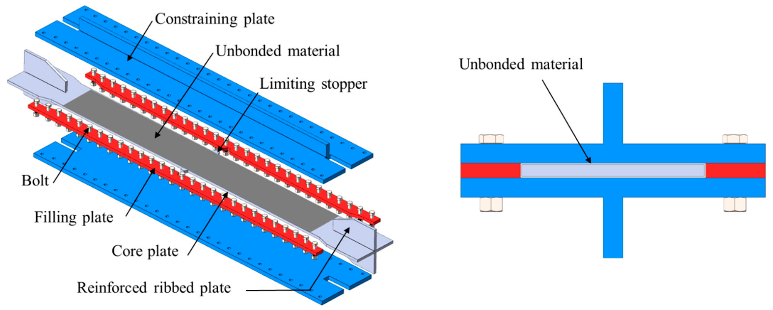
Figure 1. Structural diagram and assembly drawing of all-steel buckling-restrained brace.
Jcs 09 00581 g001
Figure 2. Schematic of the cell structure and deformation mechanisms.
Jcs 09 00581 g002
Figure 3. Diagrams of the NPR-BRB1 and PP-BRB1 (Unit: mm).
Jcs 09 00581 g003
Figure 4. Diagrams of the NPR-BRB2 and PP-BRB2 (Unit: mm).
Jcs 09 00581 g004
Figure 5. Stress–strain curves of the Q235B and LY160 specimens in the metal tensile tests.
Jcs 09 00581 g005
Figure 6. Test setup (NPR-BRB2).
Jcs 09 00581 g006
Figure 7. Loading protocol.
Jcs 09 00581 g007
Figure 8. Failure modes of the core plate for different specimens; (a) NPR-BRB1, (b) PP-BRB1.
Jcs 09 00581 g008
Figure 9. Failure modes of the core plate for different specimens; (a) NPR-BRB2, (b) PP-BRB2.
Jcs 09 00581 g009
Figure 10. Comparison of hysteresis curves derived from the experiment and finite element models.
Jcs 09 00581 g010
Figure 11. The finite element model of the NPR-BRB specimen.
Jcs 09 00581 g011
Figure 12. Comparison of the test and finite element model results, (a) NPR-BRB1, (b) NPR-BRB2, (c) the auxetic deformation of a single cell.
Jcs 09 00581 g012
Figure 13. The equivalent plastic strain of the specimens.
Jcs 09 00581 g013
Figure 14. Comparative diagram of out-of-plane buckling behavior between Q235B and LY160 core plates in the energy dissipation segment.
Jcs 09 00581 g014
Figure 15. Hysteresis curves for finite element models.
Jcs 09 00581 g015
Figure 16. The backbone curves of numerical simulation for NPR-BRBs under different influencing factors, (a) reentrant angle α, (b) section weakening rate φ .
Jcs 09 00581 g016
Table 1. Material properties.
MaterialElasticity Modulus
E (MPa)
Yield Strength
  σ y (MPa)
Tensile   Strength   σ t (MPa) Strain   at   Tensile   Strength   ε t (%)
Q235B 2.05 × 10 5 283.1418.222.2
LY160 1.95 × 10 5 181.2268.433.3
Table 2. Performance indicators of the specimens.
Specimen N T i , m a x (KN) N C i , m a x (KN) E l o n p (KJ) β ζ e q CPD
NPR-BRB165.684.4622,041.61.2880.469219.7
PP-BRB1126.9140.234,465.71.1050.382189
NPR-BRB2289.8306.974,813.81.0270.501211.3
PP-BRB2282.532176,257.71.1360.458215
NPR-BRB35952.218,530.91.1300.492223.6
PP-BRB397.9109.324,443.40.8960.535195.7
NPR-BRB4371.9422.186,275.31.1350.456188.3
PP-BRB4359.5484.890,451.31.2920.448194.5
Table 3. Parameter calibration of the Chaboche model for the Q235B and LY160 steels.
Material σ y Q b C 1 γ 1 C 2 γ 2 C 3 γ 3 C 4 γ 4
Q235B283.1101.2100,000250075001005000--
LY160181.211042991210118018012901452201
Note:  σ y represents the yield strength of the Q235B and LY160 steels,  Q denotes the maximum magnitude of change in yield surface dimensions, and b describes the rate of change in the yield surface dimensions with plastic strain.  C i denotes the initial kinematic hardening moduli, and  γ i refers to the rate of decrease in the kinematic hardening moduli with plastic strain development.
Table 4. Control parameters and performance indicators of specimens.
Specimen α (°) β (°) γ (°) φ (%) N T i , m a x (KN) N C i , m a x (KN) β E l o n p (KJ) ζ e q CPD
NPR-BRB532.510.8332.9552214.16242.321.13155,297.280.486264.35
NPR-BRB63511.6732.9252202.69233.691.15354,726.160.488263.35
NPR-BRB737.512.429.5652197.59220.281.11550,821.510.488265.66
NPR-BRB84013.3332.6452195.49214.951.150,136.190.493266.34
NPR-BRB942.514.1732.452191.02212.491.11250,461.750.566306.57
NPR-BRB237.512.437.541295.82312.091.05574,620.570.501215.49
NPR-BRB1037.512.430.2347238.35259.141.08767,023.080.513251.98
NPR-BRB1137.512.429.6457168172.591.02742,181.930.553305.33
NPR-BRB1237.512.430.3363130.74124.250.9530,122.110.443272.65
NPR-BRB1337.512.429.8868102.2580.620.78820,6710.489247.66
Disclaimer/Publisher’s Note: The statements, opinions and data contained in all publications are solely those of the individual author(s) and contributor(s) and not of MDPI and/or the editor(s). MDPI and/or the editor(s) disclaim responsibility for any injury to people or property resulting from any ideas, methods, instructions or products referred to in the content.