Abstract
This study aimed to develop an industrially scalable coating route for enhancing the oxidation resistance of carbon fiber fabrics, a critical requirement for next-generation aerospace and high-temperature composite structures. To achieve this goal, synthesis of hexagonal boron nitride (h-BN) layers was achieved via a single wet step in which the fabric was impregnated with an ammonia–borane/THF solution and subsequently nitrided for 2 h at 1000–1500 °C in flowing nitrogen. Thermogravimetric analysis coupled with X-ray diffraction revealed that amorphous BN formed below ≈1200 °C and crystallized completely into (002)-textured h-BN (with lattice parameters a ≈ 2.50 Å and c ≈ 6.7 Å) once the dwell temperature reached ≥1300 °C. Complementary XPS, FTIR and Raman spectroscopy confirmed a near-stoichiometric B:N ≈ 1:1 composition and the elimination of O–H/N–H residues as crystallinity improved. Low-magnification SEM (100×) confirmed the uniform and large-area coverage of the BN layer on the carbon fiber tows, while high-magnification SEM revealed a progressive densification of the coating from discrete nanospheres to a continuous nanosheet barrier on the fibers. Oxidation tests in flowing air shifted the onset of mass loss from 685 °C for uncoated fibers to 828 °C for the coating produced at 1400 °C; concurrently, the peak oxidation rate moved ≈200 °C higher and declined by ~40%. Treatment at 1500 °C conferred no additional benefit, indicating that 1400 °C provides the optimal balance between full crystallinity and limited grain coarsening. The resulting dense h-BN film, aided by an in situ self-healing B2O3 glaze above ~800 °C, delayed carbon fiber oxidation by ≈140 °C. Overall, the process offers a cost-effective, large-area alternative to vapor-phase deposition techniques, positioning BN-coated carbon fiber fabrics for robust service in extreme oxidative environments.
1. Introduction
Carbon fibers are widely recognized for their outstanding mechanical strength, low density, and thermal stability, making them indispensable in aerospace, automotive, and energy-related applications [1]. However, their susceptibility to oxidative degradation under high-temperature or harsh environmental conditions remains a critical limitation for their long-term structural reliability and performance [2]. Unprotected CFs lose approximately 50% of their tensile strength once the service temperature exceeds ~400 °C in air, restricting the next-generation hot-structure designs that must survive above 700 °C for hundreds of thermal cycles [3]. In response, significant efforts have been dedicated to developing advanced surface modification strategies aimed at improving the oxidation resistance of carbon fibers and their composites without compromising their inherent mechanical properties.
Early solutions relied on SiC, SiO2, Al2O3 [4], Si-O-C [5], and Si-B-C coatings [6] or suggested carbide/boride [7] layers deposited by chemical vapor deposition (CVD) or slurry routes. Although these ceramics offer good initial protection, their high elastic moduli and thermal-expansion mismatch with CFs [8,9] promote micro-crack formation during rapid heating–cooling, leading to fiber embrittlement and spallation after repeated cycling. Therefore, a lamellar, compliant coating capable of “self-sealing” defects is thus desirable.
Among the diverse nanomaterial-enabled surface modification strategies investigated thus far, hexagonal boron nitride (h-BN) stands out as a highly promising material owing to its distinctive set of physicochemical properties derived from its two-dimensional sp2-hybridized B–N lattice. These include superior in-plane thermal conductivity, exceptional chemical inertness, electrical insulation, and remarkable oxidation resistance [10,11,12]. Exhibiting a graphene-like 2D structure, hexagonal boron nitride is composed of alternating boron and nitrogen atoms arranged in a hexagonal lattice. This structure provides effective protection against oxidative and moisture-related degradation while maintaining high interfacial compatibility with both polymer and ceramic matrices [13].
Previous experimental findings have confirmed that h-BN coatings markedly improve the thermal stability of carbon fibers while mitigating oxidative deterioration under high-temperature conditions. When h-BN oxidizes above 900 °C [14], a viscous B2O3 glass forms that can flow into micro-cracks. The in situ formation of a boron oxide (B2O3) interphase during oxidation contributes to a self-healing mechanism by sealing micro-defects and impeding oxygen diffusion, further enhancing long-term thermal stability [15,16,17]. In their study, Zhao et al. [18] observed that h-BN-coated carbon fibers retained mechanical integrity and exhibited substantially reduced weight loss during high-temperature exposure. Likewise, Das et al. [19] showed that h-BN coatings delayed the onset of oxidation and improved the overall durability of fiber-reinforced composites. These findings underscore the potential of highly crystalline h-BN coatings to significantly prolong the oxidative lifespan of carbon fibers in high-temperature environments.
Recent advancements such as chemical vapor deposition (CVD) [20], atomic layer deposition (ALD) [21] and wet-coating method [22] have shown promise in the large-scale synthesis of BN coatings. Each technique, however, remains constrained by specific technical and economic limitations. CVD/ALD are throughput-limited and capital-intensive [23,24], whereas existing wet-chemical methods struggle to produce uniform, thickness-controlled coatings on large-scale fabrics [25,26]. The dip-coating technique has emerged as a highly promising alternative to chemical vapor deposition (CVD) for the fabrication of boron nitride (BN) coatings on carbon fibers, particularly in the context of industrial mass production. Unlike CVD, which requires sophisticated vacuum systems, high processing temperatures, and costly equipment, thereby limiting scalability and increasing production costs [20], dip-coating enables uniform and reliable coating formation using relatively simple setups and solution-based procedures [27]. Its ability to coat entire fiber bundles and fabrics with consistent layer quality further enhances its practicality for large-scale applications [28].
Due to its advantages, the use of h-BN coatings produced by the wet-coating method has attracted scientific attention in recent years. W. Zhou et al. [27] explored the oxidation characteristics of BN layers deposited on carbon fibers via dip-coating. The carbon fiber woven fabric was immersed in a boric acid and urea solution across three different cycles to form BN coatings with varying thickness values.
Lii et al. [28] dip-coated PAN-based carbon fibers in methanolic boric acid/urea solutions and then nitrided them in flowing NH3 at 1000 °C, producing turbostratic-BN films whose thickness (≈0.05–1 µm) parabolically scaled with solution concentration, thus its viscosity, and withdrawal speed. The coatings remained crack-free below 0.9 M solute and shifted the oxidation onset by roughly 200 °C, confirming dip-nitridation as a simple, tunable route for BN barriers on CFs. Ghanbarian & Naraghi [29] demonstrated an innovative dip-coating strategy in which carbon fibers pre-impregnated with a B4C/urea slurry were converted, via high-temperature nitriding, into a continuous, uniformly adherent and about 88 nm hexagonal-BN layer. This novel coating not only imparted pronounced thermal and environmental stability but also preserved the fibers’ exceptional mechanical properties.
Badakhsh et al. [30] applied an aqueous boric acid dip followed by NH3-assisted N2 nitriding at 1400 °C to form an approximately 0.5 µm BN sheath on PAN-based carbon fibers. It was demonstrated that the electrical resistivity of BN-modified samples increased by approximately two orders of magnitude, indicating a significant enhancement in insulating behavior. The benefit of BN coating was more pronounced in a polypropylene/graphite composite form. The through-plane thermal conductivity of the composites exhibited an approximate 60% increase (0.47 → 0.75 W m−1 K−1). It was also shown that incorporating BN–CF fillers increased the composite’s electrical-insulation capability by roughly 700%. The study has shown the wet-chemical route’s polymer matrix compatibility.
Sun et al. [31] sequentially impregnated PAN-derived carbon fiber felts with Fe/Co/Ni salts, pyrolyzed them at 650 °C, and then dip-coated the magnetic fabric in an H3BO3/urea bath and nitrided at 500 °C, forming a three-layer CF/FeCoNi/BN composite coating whose thickness-tunable BN outer skin delayed oxidation onset from ≈450 °C to ≈754 °C and retained a −10 dB microwave-absorption band across 10.6–26 GHz—clear proof that a straightforward wet-chemical route can simultaneously build multifunctional composite layers and deliver large-area, high-temperature BN barriers.
Makurunje et al. [32] nitrided desized carbon fiber cloth pre-coated from an ethanolic H3BO3/urea (1:8 by mass) sol to create a nanostructured BN interphase (about 250 nm) in carbon fiber–carbon composites. The oxyacetylene tests up to ≈2500 °C showed that the ablation rate and shrinkage of CF/BN/C laminates were threefold lower than BN-free CF/C, and the protection was attributed to self-healing B2O3 filling surface pores.
Building on these advances, this study investigates a cost-effective, scalable, and technically straightforward method for industrial production of h-BN-coated long carbon fiber fabrics, by ammonia borane, suitable for large-scale composite applications, as this has not yet been reported. Ammonia borane (BH3∙NH3) was chosen as the precursor due to its 1/1 B:N ratio, room temperature stability, and its ability to transform into h-BN through a straightforward ceramic conversion process through heating. The synthesis of the BN coating precursor involved dissolution of BH3∙NH3 in tetrahydrofuran (THF, (CH2)4O). This study addresses a critical gap in the existing literature by systematically examining the physicochemical properties of precursor solutions prior to the synthesis of h-BN via a wet-coating approach. The experimental methodology encompasses several characterization techniques, including pH measurements to determine the acidity of precursor solutions and turbidity analysis to assess the degree of precursor dissolution. Comprehensive thermal, structural, and morphological evaluations were conducted. Structural and chemical characterizations were carried out using X-ray Diffraction (XRD), X-ray Photoelectron Spectroscopy (XPS), Fourier-Transform Infrared Spectroscopy (FTIR), Raman Spectroscopy, and Scanning Electron Microscopy (SEM). In addition, the thermal behavior of the samples was investigated through Thermogravimetric Analysis (TGA) and Differential Thermal Analysis (DTA).
2. Materials and Methods
2.1. Materials
Initially, the synthesis of ammonia borane (BH3∙NH3) precursor was meticulously executed through a carefully controlled chemical process. This synthesis served as a foundational step for the subsequent pyrolytic decomposition of BH3∙NH3, which was employed to fabricate hexagonal boron nitride (h-BN) on a carbon fiber fabric substrate in the presence of a nitrogen (N2) atmosphere. The experimental procedure was facilitated by the use of ammonia formate (NH4HCO2, 97%, Sigma-Aldrich, St. Louis, MO, USA) and sodium borohydride (NaBH4, 99%, Tekkim, Ankara, Türkiye), as comprehensively detailed in Table 1. Tetrahydrofuran (THF, C4H8O, 99%, Sigma-Aldrich) was selected as the solvent due to its efficacy in the dissolution and stabilization of ammonia borane. The carbon fiber woven fabric substrate, characterized by its excellent mechanical properties and superior quality, was sourced from Hexcel Corporation, a leading supplier renowned for its high-performance materials. This meticulous approach underscores the rigor applied in ensuring the integrity and reproducibility of the experimental outcomes.

Table 1.
Materials and chemical components involved in the coating process of h-BN on carbon fiber fabrics.
2.2. Production Process
The preparation of the BH3·NH3 precursor constitutes a fundamental component of the chemical process employed for h-BN coating on carbon fiber fabrics. Figure 1 illustrates a step-by-step schematic of the synthesis procedure, presenting a clear and systematic representation of each stage. This flowchart facilitates a deeper comprehension of the intricacies associated with this essential stage of the study.
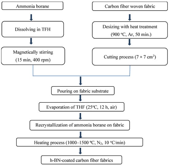
Figure 1.
Flowchart for h-BN-coated carbon fiber fabrics.
As the initial material for producing hexagonal boron nitride (h-BN), BH3∙NH3 synthesis of the precursor was achieved through a metathesis reaction using reactants such as NaBH4 and NH4HCO2, with THF serving as the solvent. BH3∙NH3 comprises B–N atomic configuration in a stoichiometric 1:1 ratio. The precursor solution for h-BN conversion was prepared using BH3∙NH3/THF, where 1 g of BH3∙NH3 was dissolved in a THF-based solution at a concentration of 0.11 g per milliliter. Subsequently, the solution underwent magnetic stirring in Heidolph model mixer at 400 rpm for 15 min at room temperature.
Preparation of the carbon fiber fabric involved a desizing process to remove the polymeric coating, to facilitate the adhesion of BN onto the carbon fibers. Desizing of the carbon fibers was achieved by heating them at 900 °C for 50 min under flowing Ar. Post-desizing, the carbon fiber fabrics were cut into 7 × 7 cm pieces in order to characterize material properties.
The coating process entailed placing the processed carbon fiber fabric substrate into a Petri dish and applying the ammonia borane solution. The solution was left to evaporate at ambient temperature and pressure for 12 h to promote the recrystallization of ammonia borane. Recrystallization was performed on the carbon fibers prepared for subsequent heating in a tube furnace (Protherm, PTF 16/50/450) which contain SiC heating element and high-density alumina tube. The thermal treatment was performed at a constant heating rate of 10 °C/min under a continuous nitrogen (N2) flow, with the target temperature held for 2 h. The process temperature varied from 1000 °C to 1500 °C in increments of 100 °C.
2.3. Characterization
2.3.1. Solution Characterizations
To examine how the properties of precursor solutions affect the structural features of h-BN coatings on carbon fiber fabrics, both turbidity and pH levels were systematically analyzed before the fabrication process. Turbidity was measured using a HACH 2100Q portable turbidimeter, HACH, Türkiye, employing standard reference solutions compatible with coating applications. Measurements were taken in a container with a 25 mm diameter and 50 mm height. The device was calibrated using Formazan standards within the 0–1000 NTU range. Following this, the pH levels of visually transparent solutions were recorded using a benchtop pH meter fitted with a Hanna HI-1230 electrode, Hanna Instruments, Türkiye allowing for the identification of each solution’s acidic or basic character.
2.3.2. Material Characterizations
Thermal behavior of the synthesized materials was examined using a Netzsch STA449F3 Differential Thermal Analysis–Thermogravimetry (DTA-TG) system, NETZSCH Group, Selb, Germany, allowing for the optimization of the thermal treatment process by tracking reaction profiles across a broad temperature spectrum. The precursor material underwent thermal analysis within a nitrogen environment, where the transformation of ammonia borane into hexagonal boron nitride (h-BN) was confirmed between 25 °C and 1300 °C at a constant heating rate of 10 °C/min. In addition, oxidation resistance of the BN-coated carbon fiber samples was evaluated under dry air flow (250 mL/min) using the same temperature range and heating rate.
X-Ray Diffraction (XRD) analysis using the Panalytical model diffractometer, Malvern Panalytical, Netherlands, was employed to identify the constituent phases in the h-BN films on carbon fiber fabrics. CuKα radiation (λ = 0.15405 nm) was used in Gonio mode over a range of 10° to 90°, with a voltage of 45 kV and a current of 40 mA applied to the Cu tube.
The surface chemistry of h-BN films on carbon fiber fabrics was analyzed using a Thermo Scientific K-Alpha X-Ray Photoelectron Spectroscopy (XPS) system, Thermo Fisher Scientific, Waltham, MA, USA. Photoelectrons were emitted by a monochromatic Al Kα X-ray source (1486.6 eV) operating at 12 kV and 3 mA (36W), and these emissions were captured with a hemispherical analyzer. 400 μm X-ray spot size was employed. Survey spectra were collected over two scans at a pass energy of 200 eV, using a 50 ms dwell time and an energy step size of 1 eV across 1361 channels. High resolution spectra for each element were acquired over their characteristic binding-energy ranges at a pass energy of 50 eV, with a 0.1 eV step size and 50 ms dwell time and averaged over 20 scans. Charge compensation was achieved by employing a low-energy electron or ion flood gun.
Fourier Transform Infrared Spectroscopy (FTIR) was used to examine the bonding properties of h-BN films on carbon fiber fabrics. The bonding properties were detected using elastic vibrational spectroscopy, spanning a wavenumber range of 400 to 4000 cm−1. The FTIR analysis with VARIAN/6660-IR model, Agilent, Santa Clara, CA, USA, was conducted on all the samples coated over a temperature range of 1000 to 1500 °C, focusing on exploring the ceramic properties.
The inelastic vibrational characteristics of h-BN films on carbon fiber fabrics were meticulously identified through Raman Spectroscopy (JASCO NRS4500). The analysis was performed across a Raman shift range of 50 to 3500 cm−1, providing a comprehensive spectral investigation that facilitated a detailed understanding of the phonon modes and the intricate bonding interactions within the composite material.
A Hitachi SU5000 Field Emission Scanning Electron Microscope (FESEM), Hitachi High-Tech Corporation, Tokyo, Japan, operated at an accelerating voltage of 10 kV, was used to characterize the surface morphology of the h-BN coatings. The instrument enabled high-resolution imaging with magnifications ranging from 1000× to 50,000×, allowing for detailed observation of the thin film’s microstructural and nanoscale features.
3. Results
3.1. Solution Characteristics
The synthesis of ammonia borane (BH3∙NH3) as a precursor for h-BN coatings involves the preparation of clear solutions from specified chemical precursors and a suitable solvent. These solutions are formulated by dissolving compounds containing metal cations, such as ammonium formate (NH4HCO2) and sodium borohydride (NaBH4), in a polar aqueous medium. Tetrahydrofuran (THF), employed as the solvent, is a moderately polar solvent capable of dissolving a broad spectrum of both non-polar and polar chemical species [33,34].
Turbidity is a parameter that reflects the degree of light scattering in liquids such as distilled water, resulting from suspended particles when exposed to a light source [35]. Elevated turbidity values correspond to increased scattering intensity and serve as an indicator of the dissolution efficiency of powdered precursors—such as NH4HCO2 and NaBH4—within the solution. Measurements are expressed in nephelometric turbidity units (NTU), with typical values spanning from 0 to 1000. A low turbidity reading, especially values approaching 0 NTU or within the 0–50 NTU range, implies effective dissolution and homogeneity, which are critical for forming stoichiometric precursors suitable for subsequent sintering steps without requiring further characterization [36,37].
In this context, the recorded turbidity value of 134.20 NTU, as presented in Table 2, indicates the presence of a semi-transparent solution containing micro-scale clusters. Although the precursor powders were entirely dissolved, the slight agglomeration of molecular clusters led to an increased turbidity, suggesting a marginal inhomogeneity at the microscopic level. These clusters contribute to light scattering and thus elevate the turbidity readings. If left unaddressed, such inhomogeneity could compromise the ceramic product’s stoichiometric accuracy [38,39]. Nevertheless, complementary characterizations via SEM, XRD, and XPS confirmed that despite the moderate turbidity level, both homogeneity and target stoichiometry were successfully achieved, validating the effectiveness of the synthesis protocol.
Table 2.
Turbidity and pH values of prepared solution.
The chemical precursors undergo reactions within a tetrahydrofuran (THF) solvent system. These interactions are effectively described by the partial charge model, which is particularly relevant in non-neutral environments (pH ≠ 7), where species such as NH4HCO2, NaBH4, and C4H8O exhibit localized charge distributions. The pH measurement of the synthesized BH3·NH3 solution was determined to be 7.58, indicating a mildly basic environment (as shown in Table 2). pH plays a pivotal role in the gelation process, as it influences the resultant structural morphology—acidic media favor the formation of branched networks, whereas basic conditions promote the formation of molecular clusters. Wet-chemical synthesis routes, particularly for complex compounds such as BH3·NH3, rely heavily on precise precursor selection and solvent conditions. Therefore, accurately assessing the solution’s acidity or basicity is a critical step prior to initiating powder synthesis protocols.
3.2. Thermal Behavior
The pyrolysis stage of the BH3∙NH3 precursor is crucial to maintaining stoichiometry and optimizing oxidation resistance properties. During pyrolysis, the BH3∙NH3 precursor undergoes decomposition, resulting in significant chemical transformations. DTA-TG analyses are utilized to monitor these transitions, facilitating the optimization of synthesis processes and enhancement of structural stability and operational performance. Figure 2 presents the results of the DTA-TG analysis conducted on BH3·NH3 material following an oven-drying process at 40 °C for 2 h under ambient air conditions. The primary production of h-BN coatings depends on the pyrolytic decomposition of the BH3∙NH3 molecule, which is influenced by both the heating rate and temperature. According to literature sources [40,41,42,43], the pyrolytic decomposition of BH3∙NH3 occurs above 1270 °C, with DTA-TG analysis typically conducted within the 0–1300 °C range, consistent with these findings. To prevent oxidation during DTA-TG analysis, a nitrogen (N2) atmosphere is employed. At low temperature decomposition, borazine (B3N3H6) and diborane (B2H6) are intermediates formed during the thermal decomposition of BH3∙NH3. The formation of these intermediates occurs at specific temperature ranges. More specifically, the theoretical hydrogen (H2) mass content in BH3∙NH3 is 19.62%. Throughout the heating process, BH3∙NH3 undergoes melting at 98 °C, identified by an endothermic peak. Following this, the first release of H2 occurs at 108.9 °C, marked by an exothermic peak and confirmed by a TG mass loss. The second exothermic peak at 128.5 °C indicates the release of borazine and H2 gases, accompanied by significant mass loss at this stage [40]. After 128.5 °C, a gradual mass loss is observed, and subsequent to the H2 release, the B and N atoms rearrange into a well-crystallized structure [41]. As indicated in Equation (1), B2H6 generally forms at slightly higher temperatures, typically between 70 °C and 100 °C, during the early stages of ammonia borane decomposition.
2BH3 → B2H6,
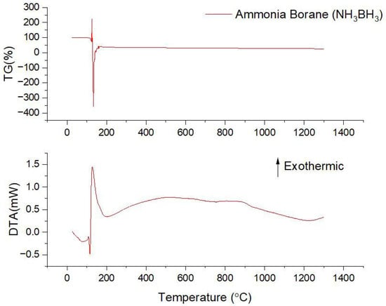
Figure 2.
The DTA-TG analysis results for BH3∙NH3 (material dried at 25 °C for 12 h under ambient atmospheric conditions).
B3N3H6 typically forms at temperatures around 100 °C to 200 °C. As ammonia borane decomposes upon heating, it releases hydrogen gas and forms borazine as one of the primary intermediates [41]. The general reaction can be represented in Equation (2):
3BH3∙NH3 → B3N3H6+6H2,
At high temperature decomposition (above 200 °C), the intermediate products further decompose, leading to the formation of amorphous BN. This process is typically observed around 1000 °C to 1200 °C. The formation of amorphous boron nitride (BN) is represented by the chemical reaction outlined in Equation (3):
B3N3H6 → 3BN + 3H2,
With continued heating, the amorphous BN starts to crystallize. This crystallization process begins around 1200 °C and becomes more significant at higher temperatures. Crystallization of hexagonal boron nitride (h-BN) generally takes place within the temperature window of 1200 °C to 1500 °C, and the corresponding reaction is presented in Equation (4):
Amorphous BN → Crystalline h-BN
The transformation of BH3∙NH3 to h-BN is a complex process involving several stages of thermal decomposition and crystallization, ultimately resulting in the formation of h-BN with distinct structural properties [42,43]. The reaction pathway can be summarized as follows: (a) BH3∙NH3 (initial precursor) → intermediate decomposed compounds + H2 (release of hydrogen gas), (b) intermediate compounds → amorphous BN, (c) amorphous BN (at 1200 °C) → onset of h-BN formation, (d) amorphous BN (at 1300 °C) → significant crystallization into h-BN and (d) amorphous BN (at 1400–1500 °C) → complete transformation into layered h-BN.
3.3. Phase Analysis
Figure 3 presents the XRD patterns of h-BN coatings on carbon fiber fabrics subjected to heat treatments ranging from 1000 °C to 1500 °C for 2 h in a N2 atmosphere. The XRD analysis reveals that boron nitride formation begins at temperatures around 1200 °C, alongside the presence of decomposed ammonia borane. Complete formation is observed at 1300 °C, consistent with previously reported findings [27,44,45]. Consequently, our results align well with the reports of Zhou et al. [27] and Kumar et al. [44], and we provide a detailed explanation here. As depicted in Figure 3, the decomposition of ammonium borane compounds extends up to 1000 °C, 1100 °C, and 1200 °C. Upon heat treatment at 1000 °C and 1100 °C, the decomposition of the BH3∙NH3 precursor in the sample structure was observed. Although intermediate phases were detected, XRD analysis confirms that these phases transform into the BN phase at 1200 °C. Following heat treatment at temperatures exceeding 1200 °C, the prominent peak which was located around 2θ~26.6° corresponds to the (002) lattice plane of hexagonal boron nitride with graphite-like ordering.
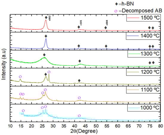
Figure 3.
The XRD patterns of h-BN coatings on carbon fiber fabrics samples were subjected to heat treatment at 1000–1500 °C for 2 h under a nitrogen atmosphere.
The formation of h-BN initiates around 1200 °C, with amorphous h-BN emerging at 1300 °C. At 1400 °C and 1500 °C, the amorphous h-BN structure fully transitions into a layered h-BN configuration. The XRD patterns obtained at 1400 °C and 1500 °C correspond closely with the ICSD collection code: 168892, referencing pattern 98-016-8892.
Elevated temperatures during heat treatment induce structural and microstructural changes, leading to variations in crystallinity. This observation is clearly reflected in the XRD patterns of the samples thermally treated at 1400 °C and 1500 °C, where the high peak intensities indicate significant crystallization. Consequently, higher temperatures promote crystal growth through coalescence, which significantly affects the material’s structural properties. Furthermore, the emergence of XRD peaks at process temperatures of 1400 °C and 1500 °C, specifically at 26.50°, 43.65°, and 54.49°, corresponds to the characteristic h-BN crystal orientation peaks of the (002), (101), and (004) planes, respectively. The peak characteristics suggest a preferential atomic arrangement along the (002) Miller plane, indicating the formation of a highly preferentially textured structure. These structural features critically affect the crystallinity and textural development of h-BN, thereby modulating its structural integrity, electronic behavior, and notably, its resistance to oxidative degradation [44,45]. By carefully controlling and optimizing the texture, it is possible to enhance the dielectric properties, surface roughness, and overall structural characteristics to achieve superior oxidation resistance performance.
Table 3 summarizes the crystallographic parameters of h-BN coatings formed on carbon fiber fabrics following heat treatment at 1400 °C and 1500 °C for 2 h in a nitrogen atmosphere. The table presents data on Miller indices, diffraction angles (2θ), full width at half maximum (FWHM), interplanar spacings (d), lattice constants (a = b and c), average crystallite sizes (D), dislocation densities, and texture coefficient (TC) values. The corresponding XRD patterns provide insight into the material’s phase state as well as its crystallographic orientation, lattice geometry, and average crystallite size. Lattice constants for the crystalline h-BN phase were calculated using Equation (5):
Table 3.
Crystallographic and microstructural parameters of h-BN coatings on carbon fiber fabrics heat-treated at 1000–1500 °C for 2 h in a nitrogen atmosphere: Miller indices, diffraction angle (2θ), full width at half maximum (FWHM), interplanar spacing (d), lattice constants (a = b and c), texturing coefficient (TC), crystallinity (C), average crystallite size (D), and dislocation density (δ).
In this context, d refers to the interplanar spacing, while a and c denote the lattice parameters, and h, k, l represent the Miller indices of the corresponding crystallographic planes. The standard way to assess material’s preferential orientation (texture) is to compare measured diffraction peak intensities with reference data from the instrument’s database. To quantify this preferential alignment, the texture coefficient (TC) is calculated using Equation (6) below [46]:
In this context, I0(hkl) refers to the standard diffraction intensity of the (hkl) plane, as obtained from reference databases (ICSD:236991), while I(hkl) represent the experimentally measured intensity for the same plane. A texture coefficient (TC) value greater than 1 indicates the presence of preferential orientation along that crystallographic direction. Furthermore, the relationship between the lattice parameters a and c of the hexagonal structure and the interplanar spacing d forms the basis for accurate crystallographic calculations.
To assess the texture evolution during the transformation of ammonia borane into boron nitride, TC values were computed using the constant background intensity method, implemented in X’Pert HighScore Plus software, Version 4.9, in accordance with Equation (7):
The mean crystallite size of the h-BN phase was calculated using the Scherrer equation, which relates peak broadening in X-ray diffraction to crystallite dimensions. The average crystallite size (D) is given by the following expression [47]:
In Equation (8), D denotes the average crystallite size, β is the full width at half maximum (FWHM) of the diffraction peak (in radians) corresponding to the specific crystallographic plane, θ is the Bragg angle, and λ represents the wavelength of the incident X-ray radiation. It is well established that a reduction in crystallite size leads to peak broadening in the XRD pattern, indicating nanoscale dimensions.
Furthermore, the dislocation density (δ)—which reflects the number of crystallographic defects within a unit volume—can be estimated based on the crystallite size. This parameter provides valuable information regarding the structural quality and crystallinity level of the material. Lower dislocation density values are generally associated with well-crystallized materials, serving as an indicator of improved lattice order.
Crystallization quality is inherently linked to the defect (dislocation) density of a material. As indicated by Equation (9), a low dislocation density corresponds to a larger crystallite size. Since crystallite size is inversely related to the full width at half maximum (FWHM) of XRD peaks, broader peaks reflect smaller domains, while narrower peaks signify well-developed crystalline regions. Therefore, a reduced FWHM can be interpreted as evidence of high crystallinity and minimal structural defects within the material [48].
The interplanar distance and lattice constants (a, b and c) in h-BN coatings on carbon fiber fabrics were calculated using the 002 index. These values were found to be the same as those on the diffraction charts. The calculated interplanar distance enabled the determination of the lattice parameters (a = b, c) of h-BN coatings on carbon fiber fabrics heat-treated at 1400 °C were found to be a = b = 2.5036 Å, c = 6.7 Å, respectively. Similarly, a, b and c lattice constants of h-BN coatings on carbon fiber fabrics heat-treated at 1500 °C were found to be a = b = 2.4960 Å, c = 6.72 Å, respectively. From Table 3, it is observed that after crystallization of h-BN, increasing the temperature leads to a reduction in lattice parameters. The observed effect is likely due to the loosening of interlayer van der Waals forces within the BN structure. As the temperature rises, h-BN begins to transition into turbostratic BN, characterized by a misalignment in the stacking of BN layers along the l indices. This transition is evident from the XRD analysis, where the most intense peak shifts from 26.5° at 1400 °C to 26.47° at 1500 °C.
The texture coefficient (TC) values of h-BN coatings formed on carbon fiber fabrics and heat-treated at 1400 °C and 1500 °C were calculated from the XRD data using Equation (6). The results revealed TC values close to 1.00, indicating a nearly random texture with a strong (002) preferential orientation, which is considered the most favorable in terms of structural stability.
The dominance of the (002) diffraction plane arises from thermodynamic considerations—specifically, the tendency of the film to grow in a manner that minimizes surface free energy. Among the observed planes, (002) at 2θ = 26.05°, (101) at 43.65°, and (004) at 54.49°, the (002) plane exhibits the lowest surface energy. Consequently, grains aligned along the (002) direction are energetically favored and grow more rapidly during thermal processing, leading to a pronounced texture along that orientation. This behavior is especially significant in solution-derived films, as it demonstrates that crystallographic orientation can be effectively controlled by optimizing processing parameters such as solvent–ligand interactions, annealing temperature, dwell time, and ambient gas atmosphere [49,50,51].
XRD analysis further showed that heat treatments at 1400 °C and 1500 °C resulted in sharp and intense (002) peaks, confirming the high degree of crystallinity in the coatings. Crystallinity was evaluated across a range of annealing temperatures using Equation (7). It was determined that the conversion of ammonia borane to crystalline h-BN begins at approximately 1200 °C. Complete crystallization was achieved at 1300 °C and above. At 1200 °C, the material retained a mixed-phase structure, with crystallinity values of 26.2% for residual ammonia borane and 73.7% for h-BN, suggesting a transition state in the crystallization process.
The average crystallite sizes of the heat-treated coatings at 1400 °C and 1500 °C were estimated using Scherrer’s equation (Equation (8)) and found to be approximately 10.10 nm and 7.72 nm, respectively (see Table 3 for detailed values). Dislocation densities, calculated using Equation (9), were determined to be 0.06 nm−3 and 0.12 nm−3 for the respective temperatures, indicating that lower annealing temperatures resulted in larger grains with fewer crystal defects.
3.4. XPS Analysis
XPS analysis was conducted on h-BN coatings deposited on carbon fiber fabrics to elucidate the surface chemistry and composition. The findings presented in Figure 4 and elaborated in Table 4 and Table 5 detail the binding energies, elemental composition, and atomic concentrations corresponding to the B 1s, N 1s, O 1s, and C 1s spectral regions. This comprehensive XPS analysis offers valuable insights into the surface chemical composition and bonding environments of the h-BN coatings. Such information is essential for evaluating their chemical stability, purity, and suitability for advanced functional applications.
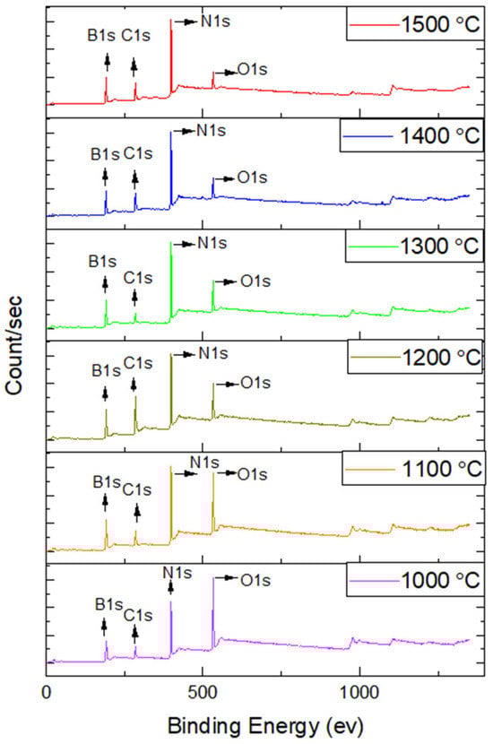
Figure 4.
The XPS analysis results of h-BN coatings on carbon fiber fabrics.
Table 4.
Binding energies of h-BN coatings on carbon fiber fabrics.
Table 5.
Compositions of h-BN coatings on carbon fiber fabrics.
The XPS analysis, augmented by argon (Ar) ion etching, affords an in-depth examination of the elemental composition and chemical bonding states across various operational coating temperatures. Figure 5 presents XPS spectra for h-BN coatings subjected to different temperatures, revealing the corresponding shifts in binding energies and elemental compositions. Table 4 presents a systematic summary of the binding energies corresponding to the B 1s, N 1s, O 1s, and C 1s spectral regions. The B 1s spectrum exhibits a prominent B–N bond peak at approximately 190.78 eV, along with a secondary B–O bond component detected near 192.05 eV. In parallel, the N 1s region displays a characteristic B–N bond at 398.37 eV and an N–H bond signal around 400.1 eV [52]. The O 1s and C 1s signals indicate the incorporation of oxygen- and carbon-containing species, which may arise from surface contamination or the intrinsic properties of the carbon fibers.
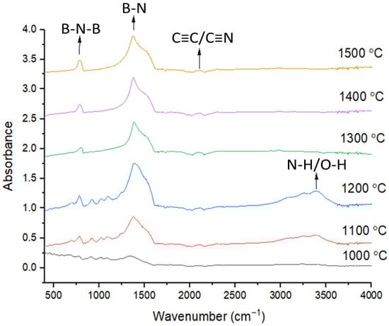
Figure 5.
The FTIR analysis results of BN coatings on carbon fiber fabrics heat-treated in the range of 1000 °C and 1500 °C.
A notable observation is the subtle shifts in the binding energies of the B 1s, N 1s, O 1s, and C 1s as heat treatment temperature increases, suggesting potential structural transformations within the h-BN coatings (detailed in Table 4). Table 5 delineates the atomic percentages of elements within the h-BN coatings, illustrating how the B/N stoichiometry evolves with temperature. Notably, as the processing temperature increases, the B/N ratio converges towards the ideal 1:1 stoichiometric ratio, indicative of a more optimal h-BN composition.
The B1s and N1s spectra distinctly reveal the presence of B-N bonds, which are foundational to the structural integrity of h-BN. The detection of N-H bonds in the N 1s spectra suggests possible surface hydrogenation, potentially influenced by the processing environment. Moreover, the data indicate that higher processing temperatures mitigate surface oxidation rates, as evidenced by the reduced intensity of the O 1s peaks. Oxidation, albeit at low levels, could occur due to atmospheric humidity, as reflected in the B-O and O 1s peaks. The presence of C 1s peaks is likely attributable to surface contamination or the inherent characteristics of the carbon fibers utilized in the substrate [53].
XPS analysis results reveal that elevating the coating operation temperatures enhances the B/N stoichiometry in h-BN coatings on carbon fiber fabrics, approaching the idealized 1:1 ratio. This analysis also underscores the significance of surface oxidation and contamination effects, providing a comprehensive understanding of the chemical composition and bonding states under varying processing temperatures, thereby offering critical insights into optimizing h-BN coatings for specific applications.
3.5. FTIR Analysis
The FTIR analysis, depicted in Figure 5, provides further characterization of the BN coatings on carbon fiber fabrics, offering insights into vibrational modes and chemical interactions. The in-plane B-N vibration, detected at 1370 cm−1, results confirm the presence of B–N bonds arranged within the hexagonal lattice of boron nitride. In addition, the characteristic out-of-plane B–N–B vibrational mode was detected at approximately 790 cm−1, further verifies the formation of the BN structure [54]. A peak at 2200 cm−1 indicates the presence of C≡C/C≡N bonds, suggesting interactions between BN and the carbon fiber, potentially forming a BN coating on the carbon fiber fabrics.
During heating, particularly notable after reaching 1000 °C, recrystallization of B and N atoms occur. This recrystallization may lead to the formation of chemical bonds between BN and functionalizes the carbon fiber surface to promote stronger bonding at the fiber–matrix interface [37]. Specifically, the formation of B-N and C=N bonds indicate strong chemical interactions between the BN coating and the carbon fiber fabric. The observed vibrational modes at 1370 cm−1 and 790 cm−1 confirm confirms the effective deposition of BN onto the carbon fiber surface.
As reported by Z. Xu et al. [55], during heat treatments at 1000 °C, 1100 °C, and 1200 °C, the band at 3407 cm−1 is ascribed to the stretching vibrations of O–H and N–H functional groups, originating from moisture adsorbed onto the surface of BN-coated carbon fibers. However, at 1300 °C, 1400 °C, and 1500 °C, the stretching vibration of these bonds is not detected because the structure has completely transformed into the h-BN structure. Furthermore, the high-temperature process (up to 1000 °C) facilitates the chemical bonding between BN and the carbon fiber, potentially leading to a stronger bond between the fiber and the matrix in composite materials.
FTIR analysis complements the XPS findings, confirming the formation of BN coatings on carbon fiber fabrics and identifying key vibrational modes characteristic of BN. The presence of C=N bonds and the effects of high-temperature heating indicate strong chemical interactions, likely enhancing the mechanical properties of the resulting composite material by providing a robust bond between the BN coating and the carbon fiber fabric.
3.6. Raman Analysis
Raman spectroscopic analysis offers complementary evidence regarding the formation and structural features of h-BN coatings on carbon fiber fabrics. Figure 6 shows the RAMAN analysis results of h-BN coatings on carbon fiber fabrics heat-treated in the range of 1000 and 1500 °C. The Raman spectra show a shift from lower to higher wavenumbers (cm−1) with increasing heating temperature. This shift suggests a transition from bulk h-BN to a thin turbostratic BN film. Turbostratic BN has a less ordered structure compared to crystalline h-BN. During pyrolytic decomposition, BN experiences mass loss. As the temperature increases, the mass loss likely results in a thinner BN coating on the carbon fiber [40].
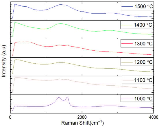
Figure 6.
The RAMAN analysis results of BN coatings on carbon fiber fabrics heat-treated in the range of 1000 °C and 1500 °C.
Important implications can be understood in structural changes, coating thickness and material properties. The Raman shift indicates structural changes in the BN coating, transitioning from a bulk h-BN form to a more disordered, thinner turbostratic BN film with increased temperature.
The thinning of the BN coating at higher temperatures could affect the composite’s mechanical strength and thermal stability. Thinner coatings might lead to different dynamic interaction between the carbon fibers and the BN coating. The shift in Raman spectra and changes in coating thickness are crucial for understanding how temperature influences the final properties of BN-coated carbon fibers, such as thermal stability, mechanical strength, and protective capabilities. Raman spectroscopy confirms the structural evolution of BN coatings on carbon fiber fabrics with increasing temperature, indicating a shift from bulk h-BN to thinner turbostratic BN films. This transition, along with the observed thinning of the BN coating due to mass loss during pyrolytic decomposition, provides valuable insights into the material behavior and potential performance of BN-coated carbon fiber composites under different thermal conditions [56].
In the B-N system, BN stands out as the sole solid binary compound. It is essential to differentiate between the (h-)sp2-hybridized forms of BN (sp2-BN) which exhibit a hexagonal structure (Figure 7), and the sp3-hybridized polymorphs of boron nitride—commonly referred to as “hard phases”—are typically synthesized under extreme conditions involving high pressure and temperature. In contrast, the sp2-hybridized form (sp2-BN) exhibits a structurally ordered arrangement composed of parallel atomic layers. This layered architecture imparts strong in-plane covalent bonding and significantly weaker van der Waals interactions between the layers, resulting in pronounced anisotropy. Such structural characteristics closely resemble those observed in graphite [57].
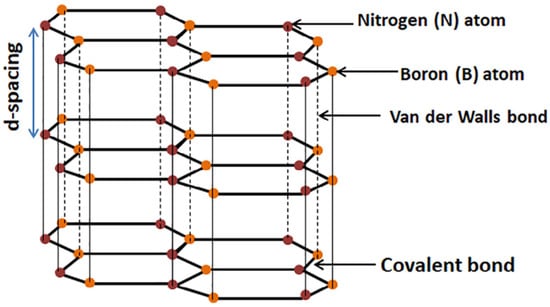
Figure 7.
Crystal structure of h-BN [57].
3.7. SEM Analysis
An extensive investigation of BN coatings on carbon fiber fabrics was conducted using SEM, revealing detailed micrographs captured at varying magnifications of 5000×, 10,000×, 25,000×, and 50,000×, as depicted in Figure 8, Figure 9, Figure 10, Figure 11, Figure 12 and Figure 13. The SEM analysis corroborates that the BN coating conforms intricately to the grooves and contours of the carbon fiber substrate. The micromorphological examination elucidates that BN predominantly forms nanospheres. These BN nanospheres likely originate due to the spatial confinement imposed by the carbon atoms from the carbon fiber. Furthermore, as the temperature increases, there is a noticeable augmentation in crystal coalescence attributable to enhanced atomic diffusion [55].
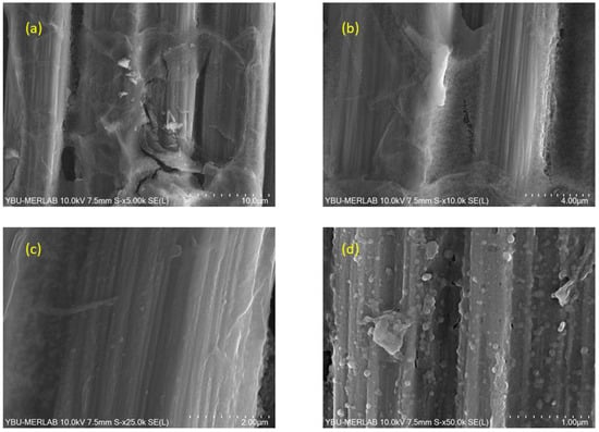
Figure 8.
SEM images of BN coatings on carbon fiber fabric heat-treated at 1000 °C, captured at varying magnifications: (a) 5000×, (b) 10,000×, (c) 25,000×, and (d) 50,000×.
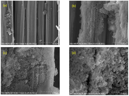
Figure 9.
SEM images of BN coatings on carbon fiber fabric heat-treated at 1100 °C, captured at varying magnifications: (a) 5000×, (b) 10,000×, (c) 25,000×, and (d) 50,000×.
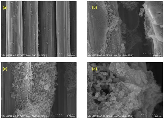
Figure 10.
SEM images of BN coatings on carbon fiber fabric heat-treated at 1200 °C, captured at varying magnifications: (a) 5000×, (b) 10,000×, (c) 25,000×, and (d) 50,000×.
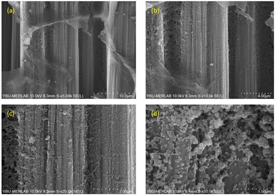
Figure 11.
SEM images of BN coatings on carbon fiber fabric heat-treated at 1300 °C, captured at varying magnifications: (a) 5000×, (b) 10,000×, (c) 25,000×, and (d) 50,000×.
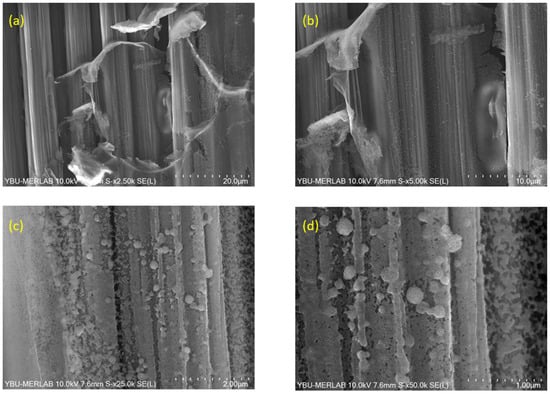
Figure 12.
SEM images of BN coatings on carbon fiber fabric heat-treated at 1400 °C, captured at varying magnifications: (a) 5000×, (b) 10,000×, (c) 25,000×, and (d) 50,000×.
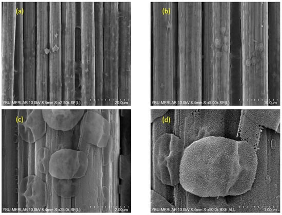
Figure 13.
SEM images of BN coatings on carbon fiber fabric heat-treated at 1500 °C, captured at varying magnifications: (a) 5000×, (b) 10,000×, (c) 25,000×, and (d) 50,000×.
Figure 8 shows SEM images of BN coating on carbon fiber fabric heat-treated at 1000 °C at different magnifications. Nanoparticles ranging between 50 nm and 150 nm characterize the production at 1000 °C. The surface morphology appears rough due to the coating on the fabric. Although there are some larger particles, the structure is predominantly composed of nanoparticles. The coating morphology appeared as nanospheres on carbon fibers. The grain size of these nanospheres ranged between 59 nm and 86 nm.
Figure 9 depicts SEM images of BN coating on carbon fiber fabric heat-treated at 1100 °C at different magnifications. The microstructural analysis reveals a higher population density of nanoparticles, accompanied by a moderate growth in particle size—some extending to nearly 200 nm in diameter, new nanoparticles ranging between 25 nm and 100 nm were detected with the rise in temperature. Additionally, the presence of nanoparticles approaching each other is evident. Globally, it is observed that there is a very thin nanotube layer on the textile substrate, giving the surface a rough appearance. In addition, nanosphere formation continues at a process temperature of 1100 °C. While the continuity of the coating is maintained, some aggregation is observed. SEM analysis clearly reveals that the coating thickness on the carbon fibers exhibits spatial variation.
Figure 10 presents SEM images of BN coating on carbon fiber fabric heat-treated at 1200 °C. Interesting results were obtained in this microstructure. Here, it was observed that nanoparticles with sizes between 20 and 40 nm merged to form larger (200–300 nm) nanosheets. It is clear that some parts of the coating still form a shell on the carbon fibers; however, this cannot be generalized to the entire carbon fiber surface. Nanosphere formation also occurs upon heat treatment at 1200 °C.
Figure 11 denotes SEM images of BN coating on carbon fiber fabric heat-treated at 1300 °C at different magnifications. Larger sheet-like structures dominate this microstructure. It is understood that the formation of new nuclei and their subsequent growth led to the thickening of the BN film. Morphological examination of the sample heat-treated at 1300 °C indicates the development of a continuous BN shell around the carbon fiber surface. Additionally, nanosphere formation is observed at this process temperature, with particle sizes ranging between 133 nm and 155 nm.
Figure 12 presents SEM images of BN coating on carbon fiber fabric heat-treated at 1400 °C at different magnifications. Here, grain growth occurred with the increase in temperature. As a result, at 1400 °C, the sizes of the nanoparticles reached up to 300–350 nm. This is reflected in the microstructure. Additionally, hints of improved surface quality of the film were observed, showing progress towards smoother surfaces. Furthermore, the morphology analysis of the sample processed at 1400 °C shows continued shell formation. The boron nitride morphology appears as nanospheres on the carbon fibers, with an average particle size measured in the range of 164–184 nm. A dense coating is also observed.
Figure 13 shows SEM images of BN coating on carbon fiber fabric heat-treated at 1500 °C at different magnifications. At 1500 °C, SEM micrographs (disregarding 15–20 nm nodules from Au sputter coating) indicate a largely continuous BN coating that preserves the longitudinal fiber grooves, upon which micron-scale, island-like lamellar BN disks nucleate and grow, yielding a hierarchical surface morphology. This has provided crucial insights into improvement in oxidation resistance of the fabrics. The highest density of the coating was obtained at this temperature. With the increasing temperature, the particle size of the BN coating increased up to 2 µm. The morphology of the BN formed as granules instead of nanospheres [58].
At low magnification, as shown in Figure 14, the BN layer exhibits macroscopically uniform coverage across the tow width, with additional continuous nanosheet network on top of the base coating. The BSE image highlights a homogeneous areal distribution of the coating, whereas the SE image resolves the interconnected sheet morphology with only occasional thicker clusters. No evidence of widespread peeling or flake-type spallation was observed in the surveyed areas, which is consistent with the XPS-mapping of B1s spectra formation, was found.
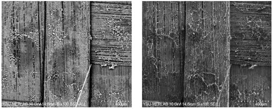
Figure 14.
Low Magnification of SEM, BSE and SE images of BN coatings on carbon fiber fabric heat-treated at 1300 °C.
SEM results confirm that the boron nitride coating fills the grooves of the carbon fiber fabric. The micromorphology shows that boron nitride tends to form nanospheres. BN nanospheres could be formed due to the restricted atoms of carbon fiber. As the temperature increases, crystal coalescence increases due to diffusion.
3.8. Oxidation Resistance Properties
Numerous studies have confirmed that boron nitride (BN) coatings significantly enhance the oxidation resistance of carbon fibers [59,60,61,62]. In the case of ammonia–borane-derived BN coatings on carbon fibers, the TG data on Figure 15 reveal that these coatings significantly improve the thermal stability of the carbon fibers, particularly under high-temperature oxidative environments. The onset of mass loss for the uncoated (desized) carbon fibers (Curve 6.3) is observed at 684.8 °C, whereas BN-coated samples at 1200 °C, 1300 °C, 1400 °C and 1500 °C (2 h) exhibit onset temperatures of approximately 717.9 °C, 785.5 °C, 827.1 °C and 826.6 °C, respectively. This systematic increase in decomposition onset with higher BN transition temperature demonstrates that better-crystallized BN layers more effectively inhibit oxidative degradation. Such findings are consistent with the pyrolysis pathway of ammonia borane, which transitions into a semi-crystalline h-BN phase (P63/mmc) upon heating between 1170 and 1500 °C. [63], and it is supported by our XRD, XPS, and FTIR analyses of samples treated between 1000 and 1500 °C. Therefore, the samples coated at 1400–1500 °C retains the highest mass in the TG plateau above 900 °C (≈97–98%), reflecting optimal BN crystallinity and coating densification. This behavior confirms that the oxidized BN network provides a highly effective barrier to oxygen diffusion.
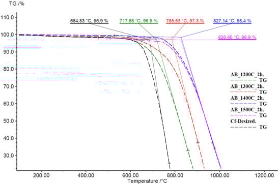
Figure 15.
S Thermogravimetric (TG) curves of BN-coated carbon fiber (CF) samples and desized CF as control.
The DTG curves highlight the kinetic differences in oxidative decomposition. The uncoated CF control exhibits a pronounced peak rate of mass loss near 720 °C, reflecting rapid fiber burnout. In contrast, as shown at Figure 16 the BN-coated sample at 1400 °C displays its maximum DTG rate shifted upwards by ~200 °C and reduced in magnitude by ~40%. This shift indicates that the coating not only delays the onset of oxidation but also moderates the reaction rate, likely by impeding oxygen access and smoothing out local hot spots.
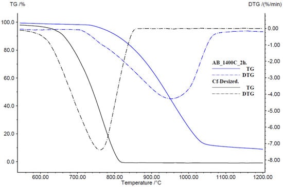
Figure 16.
Differential thermogravimetric (DTG) analysis comparing BN-coated and uncoated CF.
As detailed in [64], oxidation of boron-containing coatings produces a B2O3 interphase whose low O2 permeability further retards fiber degradation. In the case of BN-coated sample at 1400 °C, oxidation begins near 800 °C, where in situ B2O3 formation “self-heals” coating defects and enforces kinetic suppression below this threshold. Oxidation of BN nanosheets typically begins near 800 °C [65], whereas atomically thin BN demonstrates even greater resistance, with oxidation onset shifted to approximately 850 °C [66]. Therefore, any marginal weight reduction below 800 °C may be ascribed to incomplete coating formation or surface-bound volatile residues. Nevertheless, the combined effects of B2O3 interphase development and its defect healing action substantially extend operational lifetime under high-temperature conditions.
XPS analysis was performed on samples from both pre- and post-oxidation phases to investigate the oxidation resistance with the coating. Figure 17a,b show the B1s spectra of the coated samples before and after the oxidation test, respectively. The B1s spectra evidently shows the clear oxidation-induced chemical transformation of the coating. Before the oxidation test, the spectra are dominated by the BN component centered at 190.65 eV [67] with a weak shoulder at 192.3 eV [68] which is attributed to B-N-O species, possibly formed at the defect sides. After the oxidation test, which is performed up to 750 °C for best performing AB-1400 sample, a pronounced growth of the oxide component is evident in expense of the B-N peak thus B-N contribution slightly narrows and decreases in relative intensity. 0.1–0.2 eV small changes in the peak positions evident in the overlay spectra, Figure 17c, indicates local bonding arrangements.
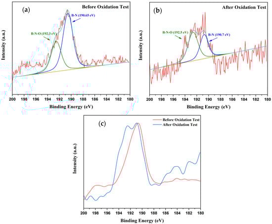
Figure 17.
Comparison of B 1s XPS spectra (a) before oxidation test, (b) after oxidation test, and (c) overlay of spectra before and after oxidation test.
The quantitative fitting results were also presented in Table 6. It is evident that before the oxidation the spectrum is dominated by BN such that B-N/B-N-O is approximately 1.86. After the oxidation the B-N/B-N-O ratio is reduced to approximately 0.39 indicating higher oxidation state. The small shift in the B-N peak together with the narrower FWHM suggest that the remaining BN after oxidation becomes structurally more uniform since more reactive/defected sites are consumed by oxidation.
Table 6.
XPS peak fitting results of B 1s, C 1s, N 1s, and O 1s before and after oxidation test, showing binding energies (BE), full width at half maximum (FWHM).
In addition to the fitting processes, XPS elemental mapping was performed on the samples before and after oxidation process (Figure 18). Even though the color bar differs between the panels due to auto scaling of counts, the XPS map suggests a clear surface modification via oxidation modification relative to pre-oxidation state. After oxidation test, O 1s intensities becomes spatially structured, whereas C 1s counts are suppressed in the same region consistent with the growth of the oxygen-containing species and shadowing the sp2-C surface. This finding is attributed to the conversion of surface BN to boron-rich oxides/oxynitrides that passivate the fiber surface with glassy-viscous oxide passivation. This is also evident from the re-distribution of the B 1s and N 1s signals.
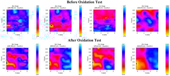
Figure 18.
XPS element distribution maps before and after oxidation: (top row) elemental maps of B 1s, N 1s, C 1s, and O 1s before oxidation and (bottom row) elemental maps of B 1s, N 1s, C 1s, and O 1s after oxidation.
4. Discussion
Thermo-gravimetric and DTA traces of the precursor showed that ammonia–borane had lost hydrogen and polymerized below 1000 °C, while the first crystalline reflections of h-BN appeared only when the dwell temperature exceeded ~1200 °C, confirming the sequence BH3∙NH3 → amorphous BN → hexagonal BN. X-ray diffraction then demonstrated a rapid rise in crystallinity: sharp (002), (101) and (004) peaks emerged at 1300 °C and sharpened further at 1400–1500 °C, where the lattice constants stabilized at a ≈ 2.50 Å and c ≈ 6.7 Å and the texture coefficient reached 1.0, evidencing a highly oriented layered structure. XPS and FTIR corroborated this structural ordering, as the B1 and N1 peaks merged on a stoichiometric 1:1 ratio and the O–H/N–H bands disappeared above 1300 °C, while the characteristic in-plane (1370 cm−1) and out-of-plane (790 cm−1) B–N vibrations sharpened remarkably. Raman spectroscopy recorded a progressive up-shift in the E2g mode, indicating that the BN layers thinned and rearranged turbostratically as the coating densified.
Morphological evidence supported this chemical evolution. SEM images revealed loosely packed 50–150 nm nanospheres at 1000–1100 °C, their coalescence into 200–350 nm nanosheets by 1200–1400 °C, and finally a compact granular film—still conformal but locally coarser (≈2 µm)—after a 2 h hold at 1500 °C. This densification governed oxidation performance: TG curves in flowing air placed the onset of fiber mass loss at 684.8 °C for bare carbon, but at 717.9, 785.5 and 827.1 °C for coatings crystallized at 1200, 1300 and 1400 °C, respectively; further heating to 1500 °C did not offer any further benefit. Corresponding DTG traces showed the peak oxidation rate shifted ~200 °C upward and attenuated by ~40% for the 1400 °C film. The improvement derived from the low oxygen permeability of the textured h-BN wall and the in situ formation of a viscous B2O3 glaze that sealed micro-defects above ~800 °C.
Taken together, the data indicated that a 2 h nitridation at 1400 °C yielded the optimum balance: complete crystallization, near-theoretical stoichiometry, minimal porosity and the highest mass retention while avoiding the grain coarsening and marginal returns observed at 1500 °C. Because the coating was deposited from a simple BH3∙NH3/THF solution and required only a single nitrogen anneal, the route proved inherently scalable and offered a cost-effective alternative to vapor-phase methods for fabric-scale oxidation protection.
The present case study on Toray T700S/T800S PAN-based carbon fiber fabrics demonstrates that heat treatments performed at 1000–1500 °C in a high-purity inert atmosphere preserve the elastic modulus and result in only negligible variations in tensile strength due to the de-sizing effect, without evidence of oxidation or structural degradation. These results are in close agreement with previous reports, which emphasize that, under oxygen-free conditions and carefully controlled thermal cycles, the adverse effects of high-temperature exposure on the mechanical integrity of PAN-based carbon fibers remain minimal [69,70]. Taken together, these findings confirm that such fibers maintain their structural and functional stability even after exposure to elevated temperatures, thereby supporting their use in high-performance applications requiring thermal resilience.
5. Conclusions
In conclusion, this study demonstrated that low-cost dip-/spray-coating of carbon fiber fabric with an ammonia–borane/THF solution, followed by a single nitrogen anneal, generated continuous, large-scale BN interphases that began as amorphous BN at ~1200 °C and transformed into highly (002)-textured hexagonal BN with lattice parameters a ≈ 2.50 Å and c ≈ 6.7 Å after 2 h at 1300–1500 °C, as confirmed by XRD, XPS, FTIR and Raman analyses. Progressive densification removed O–H/N–H contaminants and yielded a near-stoichiometric B:N ≈ 1:1 coating whose barrier quality dictated oxidation behavior: the onset of fiber mass loss in air rose from 684.8 °C (uncoated) to 717.9, 785.5 and 827.1 °C for coatings formed at 1200, 1300 and 1400 °C, with the peak oxidation rate simultaneously shifting ~200 °C higher and falling by ~40%. Processing at 1400 °C therefore provided the optimum balance of full crystallinity, minimal porosity and maximum oxidative protection, whereas 1500 °C offered no additional benefit and promoted grain coarsening; this 1400 °C condition is consequently recommended for future scale-up and mechanical-retention studies.
Author Contributions
Conceptualization, M.N.A., E.Ç. and K.Ş.; Methodology, K.Ö. and E.Ç.; Formal analysis, M.N.A., U.N., Z.B.Y.Ö., Ö.A. (Özden Acar), E.Ç. and K.Ş.; Investigation, C.Y.E., M.N.A., U.N. and K.Ş.; Data curation, C.Y.E., M.N.A., K.Ö., U.N., Z.B.Y.Ö., Ö.A. (Özden Acar) and E.Ç.; Writing—original draft, K.Ö., E.Ç. and K.Ş.; Writing—review & editing, C.Y.E., M.N.A., U.N., S.A., E.Ç. and K.Ş.; Visualization, M.N.A. and K.Ö.; Supervision, S.A., Ö.A. (Özkan Altay) and E.Ç.; Project administration, Ö.A. (Özkan Altay). All authors have read and agreed to the published version of the manuscript.
Funding
This research was partially funded by Turkish Aerospace (TUSAS) under Project No. 2089332022226.
Data Availability Statement
The original contributions presented in this study are included in the article material. Further inquiries can be directed to the corresponding author.
Acknowledgments
Authors would like thank Turkish Aerospace (TUSAS) for partially funding the research and Boron Research Institute (BOREN) in Ankara, Turkey, for the collaboration on this research endeavor.
Conflicts of Interest
Authors, Kaan Ors, Ugur Nakas, Ozkan Altay, Erdal Celik, and Korhan Sahin, were employed by Turkish Aerospace Industries Inc. The remaining authors declare that the research was conducted in the absence of any commercial or financial relationships that could be construed as a potential conflict of interest.
Abbreviations
The following abbreviations are used in this manuscript:
| CVD | Chemical Vapor Deposition |
| DTA | Differential Thermal Analysis |
| FTIR | Fourier-Transform Infrared Spectroscopy |
| FWHM | Full Width at Half Maximum |
| NTU | Measured Turbidity |
| SEM | Scanning Electron Microscopy |
| TC | Texture Coefficient |
| TGA | Thermogravimetric Analysis |
| THF | Tetrahydrofuran |
| XPS | X-ray Photoelectron Spectroscopy |
| XRD | X-ray Diffraction |
References
- Bunsell, A.R.; Renard, J. Fundamentals of Fibre Reinforced Composite Materials, 1st ed.; CRC Press: Boca Raton, FL, USA, 2005. [Google Scholar] [CrossRef]
- Panerai, F.; Cochell, T.; Martin, A.; White, J.D. Experimental measurements of the high-temperature oxidation of carbon fibers in oxygen flow. Int. J. Heat Mass Transf. 2019, 136, 184–195. [Google Scholar] [CrossRef]
- Feih, S.; Mouritz, A.P. Tensile properties of carbon fibres and carbon fibre–polymer composites in fire. Compos. Part A Appl. Sci. Manuf. 2012, 43, 765–772. [Google Scholar] [CrossRef]
- Wang, Y.-Q.; Zhou, B.-L.; Wang, Z.-M. Oxidation protection of carbon fibers by coatings. Carbon 1995, 33, 427–433. [Google Scholar] [CrossRef]
- Xia, K.-D.; Lu, C.-X.; Yang, Y. Improving the oxidation resistance of carbon fibers using silicon oxycarbide coatings. Carbon 2015, 93, 1086–1094. [Google Scholar] [CrossRef]
- Zuo, X.; Zhang, L.; Liu, Y.; Cheng, L.; Xia, Y. Oxidation behaviour of two-dimensional C/SiC modified with self-healing Si–B–C coating in static air. Corros. Sci. 2012, 65, 87–93. [Google Scholar] [CrossRef]
- Yang, X.; Chen, Z.-H.; Feng, C. High-temperature protective coatings for C/SiC composites. J. Asian Ceram. Soc. 2014, 2, 305–309. [Google Scholar] [CrossRef]
- Krenkel, W. Carbon fibre reinforced silicon carbide composites (C/SiC, C/C-SiC). Ceram. Eng. Sci. Proc. 2003, 24, 117–148. [Google Scholar] [CrossRef]
- Qi, Y.; Gao, J.; Liang, W.; Miao, Q.; Jia, F.; Chang, X.; Lin, H. A comparison of the tribological properties of SiC coatings prepared via atmospheric plasma spraying and chemical vapor deposition for carbon/carbon composites. Lubricants 2024, 12, 301. [Google Scholar] [CrossRef]
- Zhi, C.; Bando, Y.; Tang, C.; Golberg, D. Engineering of electronic structure of boron-nitride nanotubes by covalent functionalization. Phys. Rev. B 2006, 74, 153413. [Google Scholar] [CrossRef]
- Kim, G.; Lee, D.; Shanker, A.; Shao, L.; Kwon, M.; Gidley, D.; Kim, J.; Pipe, K. High thermal conductivity in amorphous polymer blends by engineered interchain interactions. Nat. Mater. 2015, 14, 295–300. [Google Scholar] [CrossRef]
- Lipp, A.; Schwetz, K.A.; Hunold, K. Boron nitride (BN) and BN composites for high-temperature applications. J. Eur. Ceram. Soc. 2008, 28, 1105–1109. [Google Scholar] [CrossRef]
- Pakdel, A.; Bando, Y.; Golberg, D. Nano boron nitride flatland. Chem. Soc. Rev. 2014, 43, 934–959. [Google Scholar] [CrossRef]
- Oda, K.; Yoshio, T. Oxidation kinetics of hexagonal boron nitride powder. J. Mater. Sci. 1993, 28, 6562–6566. [Google Scholar] [CrossRef]
- Song, C.; Ye, F.; Cheng, L.; Liu, Y.; Zhang, Q. Long-term ceramic matrix composite for aeroengine. J. Adv. Ceram. 2022, 11, 1343–1374. [Google Scholar] [CrossRef]
- Basche, M.; Fanti, R.; Galasso, F. Preparation and properties of silicon carbide-coated boron filaments. Fibre Sci. Technol. 1968, 1, 19–24. [Google Scholar] [CrossRef]
- Chen, X.; Cao, H.; He, Y.; Zhou, Q.; Li, Z.; Wang, W.; He, Y.; Tao, G.; Hou, C. Advanced functional nanofibers: Strategies to improve performance and expand functions. Front. Optoelectron. 2022, 15, 50. [Google Scholar] [CrossRef]
- Zhao, P.; Ren, Z.; Lu, C.; Lv, X.; Yang, Y. Preparation and oxidation resistance property of PyC/BN composite coating on the CF surface. New Chem. Mater. 2022, 50, 86–89. [Google Scholar] [CrossRef]
- Das, M.; Choudhury, A.; Karak, N.; Dolui, S.K. Effect of activation on boron nitride coating on carbon fiber. Ceram. Int. 2011, 37, 527–532. [Google Scholar] [CrossRef]
- Malik, M.W.; Ullah, S.; Wang, B.; Jaddi, S.; Zeng, Y.; Raskin, J.P. Oxygen activated CVD growth of large-area multilayer h-BN on polycrystalline copper foils. J. Cryst. Growth 2023, 606, 127088. [Google Scholar] [CrossRef]
- Coy, E.; Siuzdak, K.; Grądzka-Kurzaj, I.; Sayegh, S.; Weber, M.; Ziółek, M.; Bechelany, M.; Iatsunskyi, I. Exploring the effect of BN and BN bridges on the photocatalytic performance of semiconductor heterojunctions: Enhancing carrier transfer mechanism. Appl. Mater. Today 2021, 24, 101095. [Google Scholar] [CrossRef]
- Nöth, A.; Maier, J.; Schönfeld, K.; Klemm, H. Wet chemical deposition of BN, SiC and Si3N4 interphases on SiC fibers. J. Eur. Ceram. Soc. 2021, 41, 2988–2994. [Google Scholar] [CrossRef]
- Karimzadeh, S.; Safaei, B.; Yuan, C.; Jen, T.C. Emerging atomic layer deposition for the development of high-performance lithium-ion batteries. Electrochem. Energy Rev. 2023, 6, 24. [Google Scholar] [CrossRef]
- Jeong, H.; Kim, D.Y.; Kim, J.; Moon, S.; Han, N.; Lee, S.H.; Okello, O.F.N.; Song, K.; Choi, S.-Y.; Kim, J.K. Wafer-scale and selective-area growth of high-quality hexagonal boron nitride on Ni (111) by metal-organic chemical vapor deposition. Sci. Rep. 2019, 9, 5736. [Google Scholar] [CrossRef]
- Wang, F.; Zhang, X.; Du, Y.; Ou, Y.; Song, Q.; Liu, T.; Wu, X.; Tan, S.; Wang, B. Overall fabrication of uniform BN interphase on 2.5 D-SiC fabric via precursor-derived methods. Vacuum 2024, 230, 113727. [Google Scholar] [CrossRef]
- Hurwitz, F.I.; Chayka, P.V.; Scott, J.M.; Wheeler, D.R. BN and Si-Doped BN Coatings on Woven Fabrics; NASA Technical Report No. NASA/CR-2002-211438; NASA Glenn Research Center: Cleveland, OH, USA, 2002. Available online: https://ntrs.nasa.gov/api/citations/20020072716/downloads/20020072716.pdf (accessed on 18 September 2025).
- Zhou, W.; Xiao, P.; Li, Y.; Zhou, L. Dielectric properties of BN modified carbon fibers by dip-coating. Ceram. Int. 2013, 39, 6569–6576. [Google Scholar] [CrossRef]
- Lii, D.F.; Huang, J.L.; Tsui, L.J.; Lee, S.M. Formation of BN films on carbon fibers by dip-coating. Surf. Coat. Technol. 2002, 150, 269–276. [Google Scholar] [CrossRef]
- Ghanbarian, M.; Naraghi, M. Strength-preserving Continuous Hexagonal Boron Nitride Coatings on Carbon Fibers via B4C as Precursor. Carbon 2025, 241, 120380. [Google Scholar] [CrossRef]
- Badakhsh, A.; Han, W.; Jung, S.C.; An, K.H.; Kim, B.J. Preparation of boron nitride-coated carbon fibers and synergistic improvement of thermal conductivity in their polypropylene-matrix composites. Polymers 2019, 11, 2009. [Google Scholar] [CrossRef]
- Sun, Q.; Ye, W.; Cheng, J.; Long, X. Effects of Boron Nitride Coatings at High Temperatures and Electromagnetic Wave Absorption Properties of Carbon Fiber-Based Magnetic Materials. J. Nanomater. 2020, 2020, 3672517. [Google Scholar] [CrossRef]
- Makurunje, P.; Wesley-Smith, J.; Dziike, F.; Sigalas, I. Nanostructured boron nitride fiber/matrix interphase in carbon-carbon composites. In Ceramic Science and Engineering; Elsevier: Amsterdam, The Netherlands, 2022; pp. 189–212. [Google Scholar] [CrossRef]
- Levy, D.; Zayat, M. (Eds.) The Sol-Gel Handbook, 3 Volume Set: Synthesis, Characterization, and Applications; John Wiley Sons: Hoboken, NJ, USA, 2015; Volume 2. [Google Scholar] [CrossRef]
- Brinker, C.J.; Scherer, G.W. Sol-Gel Science: The Physics and Chemistry of Sol-Gel Processing; Gulf Professional Publishing: Oxford, UK, 1990. [Google Scholar] [CrossRef]
- Jodati, H.; Tezcaner, A.; Evis, Z.; Alshemary, A.Z.; Çelik, E. Synthesis of baghdadite using modified sol–gel route and investigation of its properties for bone treatment applications. J. Korean Ceram. Soc. 2023, 60, 381–398. [Google Scholar] [CrossRef]
- Waghchaure, R.H.; Adole, V.A.; Kushare, S.S.; Shinde, R.A.; Jagdale, B.S. Visible light prompted and modified ZnO catalyzed rapid and efficient removal of hazardous crystal violet dye from aqueous solution: A systematic experimental study. Results Chem. 2023, 5, 100773. [Google Scholar] [CrossRef]
- Çelik, E.; Aybarc, U.; Ebeoğlugil, M.F.; Birlik, İ.; Çulha, O. ITO films on glass substrate by sol–gel technique: Synthesis, characterization and optical properties. J. Sol-Gel Sci. Technol. 2009, 50, 337–347. [Google Scholar] [CrossRef]
- Danks, A.E.; Hall, S.R.; Schnepp, Z. The evolution of ‘sol–gel’ chemistry as a technique for materials synthesis. Mater. Horiz. 2016, 3, 91–112. [Google Scholar] [CrossRef]
- Hsueh, T.J.; Hsu, C.L.; Chang, S.J.; Chen, I.C. Laterally grown ZnO nanowire ethanol gas sensors. Sens. Actuators B Chem. 2007, 126, 473–477. [Google Scholar] [CrossRef]
- Baitalow, F.; Baumann, J.; Wolf, G.; Jaenicke-Rößler, K.; Leitner, G. Thermal decomposition of B–N–H compounds investigated by using combined thermoanalytical methods. Thermochim. Acta 2002, 391, 159–168. [Google Scholar] [CrossRef]
- Bowden, M.; Autrey, T.; Brown, I.; Ryan, M. The thermal decomposition of ammonia borane: A potential hydrogen storage material. Curr. Appl. Phys. 2008, 8, 498–500. [Google Scholar] [CrossRef]
- Zhong, B.; Zhao, G.; Huang, X.; Zhang, X.; Chen, J.; Ren, H.; Wen, G. A facile route to high-purity BN nanoplates with ultraviolet cathodoluminescence emissions at room temperature. Mater. Res. Bull. 2014, 53, 190–195. [Google Scholar] [CrossRef]
- Babenko, V.; Lane, G.; Koos, A.A.; Murdock, A.T.; So, K.; Britton, J.; Meysami, S.S.; Moffat, J.; Grobert, N. Time dependent decomposition of ammonia borane for the controlled production of 2D hexagonal boron nitride. Sci. Rep. 2017, 7, 14297. [Google Scholar] [CrossRef] [PubMed]
- Kumar, A.; Malik, G.; Pandey, M.K.; Chandra, R.; Mulik, R.S. Corrosion behavior of pulse laser deposited 2D nanostructured coating prepared by self-made h-BN target in salinity environment. Ceram. Int. 2021, 47, 12537–12546. [Google Scholar] [CrossRef]
- Zhu, M.; Shao, Y.; Xin, Y.; Yang, D.; Lu, X.; Zhang, H. Anisotropic dielectric dispersions and thermal behaviors in highly textured BN thin films for heat self-dissipating electronics. Vacuum 2024, 225, 113207. [Google Scholar] [CrossRef]
- Barrett, C.S.; Massalski, T.B. Structure of Metals: Crystallographic Methods, Principles, and Data, 3rd ed.; Pergamon Press: South Croydon, UK, 1980. [Google Scholar]
- Aksoy, S. Physical Characterization of Nano-Structured Metal Oxide Films Obtained by Sol Gel Spin Coating Method. Doctoral Dissertation, Anadolu University, Institute of Science and Technology, Eskişehir, Turkey, 2017. [Google Scholar]
- Vyazovkin, S.; Koga, N.; Schick, C. (Eds.) Handbook of Thermal Analysis and Calorimetry: Recent Advances, Techniques and Applications; Elsevier: Amsterdam, The Netherlands, 2018. [Google Scholar]
- Zhang, Y.; Lin, B.; Fu, Z.; Liu, C.; Han, W. Strong ultraviolet emission and rectifying behavior of nanocrystalline ZnO films. Opt. Mater. 2006, 28, 1192–1196. [Google Scholar] [CrossRef]
- Bura, M.; Singh, G.; Gupta, D.; Malik, N.; Salim, A.; Kumar, A.; Singhal, R.; Kumar, S.; Aggarwal, S. Transition in the preferred orientation of RF sputtered ZnO/Si thin films by thermal annealing: Structural, morphological, and optical characteristics. Opt. Mater. 2022, 133, 113024. [Google Scholar] [CrossRef]
- Budak, E.; Bozkurt, Ç. Synthesis of hexagonal boron nitride with the presence of representative metals. Phys. B Condens. Matter 2010, 405, 4702–4705. [Google Scholar] [CrossRef]
- Sun, T.; Tu, J.; Zhou, Z.; Sun, R.; Zhang, X.; Li, H.; Xu, Z.; Peng, Y.; Liu, X.; Wangyang, P.; et al. Resistive switching of self-assembly stacked h-BN polycrystal film. Cell Rep. Phys. Sci. 2022, 3, 100939. [Google Scholar] [CrossRef]
- Jia, S.; Chen, W.; Zhang, J.; Lin, C.Y.; Guo, H.; Lu, G.; Li, K.; Zhai, T.; Ai, Q.; Lou, J. CVD growth of high-quality and large-area continuous h-BN thin films directly on stainless-steel as protective coatings. Mater. Today Nano 2021, 16, 100135. [Google Scholar] [CrossRef]
- Bashir, A.; Maqbool, M.; Lv, R.; Usman, A.; Guo, H.; Aftab, W.; Niu, H.; Liu, M.; Bai, S.L. Surface modified boron nitride towards enhanced thermal and mechanical performance of thermoplastic polyurethane composite. Compos. Part B Eng. 2021, 218, 108871. [Google Scholar] [CrossRef]
- Xu, Z.; Chen, Y.; Li, W.; Li, J.; Yu, H.; Liu, L.; Wu, G.; Yang, T.; Luo, L. Preparation of boron nitride nanosheet-coated carbon fibres and their enhanced antioxidant and microwave-absorbing properties. RSC Adv. 2018, 8, 17944–17949. [Google Scholar] [CrossRef]
- Nehate, S.D.; Saikumar, A.K.; Prakash, A.; Sundaram, K.B. A review of boron carbon nitride thin films and progress in nanomaterials. Mater. Today Adv. 2020, 8, 100106. [Google Scholar] [CrossRef]
- Ramteke, S.M.; Chelladurai, H. Effects of hexagonal boron nitride based nanofluid on the tribological and performance, emission characteristics of a diesel engine: An experimental study. Eng. Rep. 2020, 2, 12216. [Google Scholar] [CrossRef]
- Fenetaud, P.; Jacques, S. SiC/SiC ceramic matrix composites with BN interphase produced by gas phase routes: An overview. Open Ceram. 2023, 15, 100396. [Google Scholar] [CrossRef]
- Li, J.S.; Zhang, C.R.; Li, B. Preparation and characterization of boron nitride coatings on carbon fibers from borazine by chemical vapor deposition. Appl. Surf. Sci. 2011, 257, 7155–7160. [Google Scholar] [CrossRef]
- Rousseas, M.; Mickelson, W.; Zettl, A.K. Boron Nitride Converted Carbon Fiber. U.S. Patent No. 9,305,677, 2016. [Google Scholar]
- Ghanbarian, M.; Naraghi, M. Hexagonal boron nitride coatings for thermally resistant and strong carbon fibers. SSRN Electron. J. 2024, 1–19. [Google Scholar] [CrossRef]
- Xiao, P.; Liu, Z.; Li, Z.C.; Zhang, B.; Li, Z.; Li, Y. Oxidation behavior of carbon/carbon-boron nitride composites fabricated by additives and chemical vapor infiltration. Ceram. Int. 2019, 45, 4335–4341. [Google Scholar] [CrossRef]
- Frueh, S.; Kellett, R.; Mallery, C.; Molter, T.; Willis, W.S.; Kingondu, C.; Suib, S.L. Pyrolytic decomposition of ammonia borane to boron nitride. Inorg. Chem. 2010, 50, 783–792. [Google Scholar] [CrossRef]
- Arık, M.N.; Yıldırım, C.; Solak, N. Improving the oxidation resistance of carbon fibers via B4C coating by modified boron oxide chemical vapor deposition. Solid State Sci. 2023, 146, 107367. [Google Scholar] [CrossRef]
- Li, L.H.; Cervenka, J.; Watanabe, K.; Taniguchi, T.; Chen, Y. Strong oxidation resistance of atomically thin boron nitride nanosheets. ACS Nano 2014, 8, 1457–1462. [Google Scholar] [CrossRef]
- Sarma, S.S.; Padya, B.; Sarada, B.V.; Akhila, V.; Gowthami, C.; Krishna, P.V.; Joardar, J. Two-dimensional hexagonal boron nitride by cryo-milling: Microstructure and oxidation behavior at elevated temperature. J. Nanoparticle Res. 2024, 26, 80. [Google Scholar] [CrossRef]
- Shen, T.; Liu, S.; Yan, W.; Wang, J. Highly efficient preparation of hexagonal boron nitride by direct microwave heating for dye removal. J. Mater. Sci. 2019, 54, 8852–8859. [Google Scholar] [CrossRef]
- Bresnehan, M.S.; Hollander, M.J.; Wetherington, M.; Wang, K.; Miyagi, T.; Pastir, G.; Snyder, D.W.; Gengler, J.J.; Voevodin, A.A.; Mitchel, W.C.; et al. Prospects of direct growth boron nitride films as substrates for graphene electronics. J. Mater. Res. 2014, 29, 459–471. [Google Scholar] [CrossRef]
- Sauder, C.; Lamon, J.; Pailler, R. The tensile behaviour of carbon fibres at high temperatures up to 2400 °C. Carbon 2004, 42, 715–725. [Google Scholar] [CrossRef]
- Toray Carbon Fibers. Toray T700S/T800S Technical Data Sheet; Toray Composite Materials America, Inc.: Tacoma, WA, USA, 2023; Available online: https://www.toraycma.com/resources/carbon-fiber-terminology/ (accessed on 18 September 2025).
Disclaimer/Publisher’s Note: The statements, opinions and data contained in all publications are solely those of the individual author(s) and contributor(s) and not of MDPI and/or the editor(s). MDPI and/or the editor(s) disclaim responsibility for any injury to people or property resulting from any ideas, methods, instructions or products referred to in the content. |
© 2025 by the authors. Licensee MDPI, Basel, Switzerland. This article is an open access article distributed under the terms and conditions of the Creative Commons Attribution (CC BY) license (https://creativecommons.org/licenses/by/4.0/).